VF7-41H11-S07中文资料
安徽伟仪科技有限公司产品选型手册说明书

安徽伟仪科技有限公司Anhui WEYII Science And Technology Co.,L TD.产品选型手册PRODUCT SELECTION GUIDE安徽伟仪科技有限公司Anhui WEYII Science And Technology Co.,L TD.地址(ADD):安徽省合肥市高新区创新大道2700号电话(TEL):400-997-0788 专注于气密检漏仪与气密检测设备专心 专注 专业专注于气密检漏仪与气密检测设备专心 专注 专业感谢以下品牌的长期支持与合作!安徽伟仪科技有限公司位于合肥市国家高新技术产业开发区,是一家专业从事气密检漏仪、气密检测设备、流体控制与气动技术领域的研发、生产与服务的高新技术企业。
Anhui Weiyi Technology Co., Ltd. is located in Hefei National High-tech Industrial Development Zone. Weiyi is a high-tech manufacturer specializing in R &D and service of air tightness detector, air tightness detection related equipment, fluid control and pneumatic technology.Since the establishment, We has always adhered to the management principle of talent oriented and core technology centered.Weiyi has gathered a large number of elites in the industry as technical backbones relying on the resources of China University of science and technology, Hefei University of Technolo-gy and other scientific research institutes. The advanced detection technology and design in China and abroad is combined with Weiyi's innovation also the requirement of customers. More professional solutions could provided based on this. We believe continuous improvement of product quality keeps its core competitiveness in the fierce market competition.We always strive for continuous innovation and excellence. We aim to win customers' trust with perfect products and high-quality services. We are concen-trating on being the first choice within international market.公司自成立以来,始终坚持以人才为本、核心技术为中心的经营原则,同时依托中科大、合工大及科研院所为资源,汇聚大量业内精英作为技术骨干,将国内外先进的检测技术、设计思路与伟仪的创新理念及用户的实际需求相结合,为客户提供更专业的解决方案,完善产品质量,使其在激烈的市场竞争中保持核心竞争力。
NS4110用户手册V1.1中文资料

N S4110用户手册V1.1深圳市纳芯威科技有限公司2014年06月修改历史日期版本作者修改说明目录1功能说明 (5)2主要特性 (5)3应用领域 (5)4典型应用电路 (5)5极限参数 (6)6电气特性 (6)7芯片管脚描述 (7)7.1 NS4110封装管脚分配图 (7)7.2 NS4110引脚功能描述 (7)8NS4110典型参考特性 (8)9NS4110应用说明 (8)9.1 芯片基本结构描述 (8)9.2 工作模式控制端CTRL (9)9.3 NS4110应用图示 (10)9.3.1 差分输入模式 (10)9.3.2 单端输入模式 (10)9.4 NS4110应用参数设置 (10)9.4.1 放大器增益设置 (10)9.4.2 输入电容Ci的选取 (11)9.4.3 电源去耦电容 (12)9.5 输出滤波器 (12)9.6 layout建议 (13)9.7 测试电路 (13)10芯片的封装 (14)图目录图1 NS4110典型应用电路 (5)图2 NS4110封装管脚分配图(top view) (7)图3 NS4110原理框图 (8)图4 CTRL引脚外接器件设置 (9)图5 差分输入模式 (10)图6 单端输入模式 (10)图7 输入高通网络 (11)图8 输入高通滤波器曲线 (11)图9 输出端加磁珠应用图 (12)图10 负载为8Ω,转折频率为27kHz的LC输出滤波器 (12)图11 负载为4Ω,转折频率为27kHz的LC输出滤波器 (13)图12 NS4110测试电路 (13)图13 eSOP-8封装尺寸图 (14)表目录表1 芯片最大物理极限值 (6)表2 NS4110电气特性 (6)表3 NS4110管脚描述 (7)表4 芯片工作模式与CTRL管脚电压关系 (9)表5 工作模式 (9)表6 (9)CTRL外围器件设置1功能说明NS4110是一款差分输入,AB/D类工作模式可切换,超低EMI,无需滤波器,10W的单声道音频功率放大器。
H11A1G中文资料
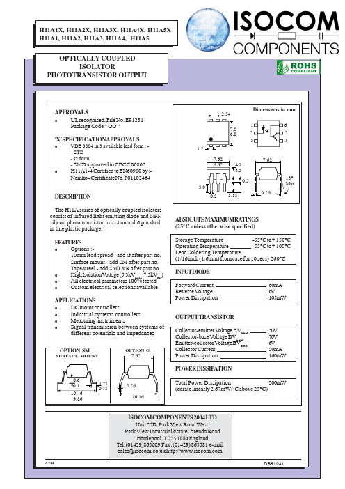
7.62
0.6 0.1 10.46 9.86
1.25 0.75
0.26 10.16
Total Power Dissipation 200mW (derate linearly 2.67mW/°C above 25°C)
ISOCOM COMPONENTS 2004 LTD Unit 25B, Park View Road West, Park View Industrial Estate, Brenda Road Hartlepool, TS25 1UD England Tel: (01429)863609 Fax : (01429) 863581 e-mail sales@
OPTION SM
SURFACE MOUNT OPTION G
0.5
3.35
ABSOLUTEMAXIMUMRATINGS (25°C unless otherwise specified) Storage Temperature -55°C to + 150°C Operating Temperature -55°C to + 100°C Lead Soldering Temperature (1/16 inch (1.6mm) from case for 10 secs) 260°C INPUTDIODE Forward Current Reverse Voltage Power Dissipation OUTPUT TRANSISTOR Collector-emitter Voltage BVCEO Collector-base Voltage BVCBO Emitter-collector Voltage BVECO Collector Current Power Dissipation POWER DISSIPATION 30V 70V 6V 50mA 160mW 60mA 6V 105mW
ISIS 7 Professional元件名称清单
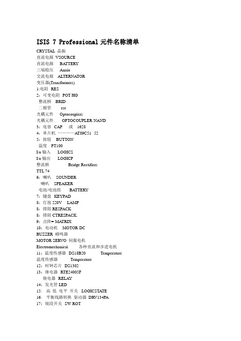
ISIS 7 Professional元件名称清单CRYSTAL 晶振直流电源VSOURCE直流电源BATTERY三端稳压Analo交流电源ALTERNATOR变压器(Transformers)1:电阻--RES2:可变电阻--POT-HG整流桥BRID二极管----rse光耦元件Optocouplers光耦元件OPTOCOUPLER-NAND3:电容--CAP 或16284:单片机————AT89C51--525:按钮--BUTTON温度---PT100I/o输入-----LOGICSI/o输出-----LOGICP整流桥Bridge RectifiersTTL 746:喇叭--SOUNDER喇叭--SPEAKER电池/电池组BATTERY7:键盘--KEYPAD8:灯泡220V----LAMP8:排阻RESPACK-8:排阻CTRESPACK9:点阵=-MATRIX10:电动机--MOTOR-DCBUZZER 蜂鸣器MOTOR SERVO 伺服电机Electromechanical 各种直流和步进电机11:温度传感器--DS18B20 Temperature温度传感器Temperature12:时钟芯片--DS130213:继电器--RTE24005F继电器--RELAY14:发光管LED-15: 高低电平开关-LOGICSTA TE16: 平衡线路转换驱动器DRV134PA17:坡段开关--SW-ROT-18:液晶1602--LM020L19 晶振--CRYSTAL20:状态显示口LOGICPROBECRYSTAL 晶振74Ls00 与非门74LS04 非门74LS08 与门74LS390 TTL 双十进制计数器7SEG 4针BCD-LED 输出从0-9 对应于4根线的BCD码7SEG 3-8译码器电路BCD-7SEG[size=+0]转换电路ALTERNATOR 交流发电机AMMETER-MILLI mA安培计AND 与门BA TTERY 电池/电池组BUS 总线CAP 电容CAPACITOR 电容器CLOCK时钟信号源CRYSTAL 晶振D-FLIPFLOP D触发器FUSE 保险丝GROUND 地LAMP 灯LED-RED 红色发光二极管LM016L 2行16列液晶可显示2行16列英文字符,有8位数据总线D0-D7,RS,R/W,EN三个控制端口(共14线),工作电压为5V。
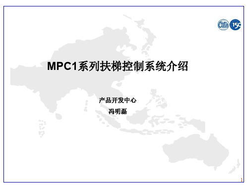
西子奥的斯MPC 系列扶梯控制原理
扶梯远程监控系统界面
22
可选
火警急停
23
可选
ETA-PLUS
24
可选
故障指示灯
25
可选
液位开关
26
可选
润滑系统
27
可选
双回路制动系统
29
可选
油位检测
30
可选
乘客检测器/计数器
31
可选
干触点
32
可选
梯级照明
33
可选
裙板照明
34
可选
自动停止
35
可选
远程启停
7
系统组成 机房布局
8
系统组成 扶梯控制柜布局
附加制动器: 主机超速、非操纵逆转、主驱动断链、断电情况下动作 动作后显示5,只能开上行复位 如果自动启动运行上行,8秒内如果检测不到附加制动器复位,会自 动停止运行,需要重新启动上行或检查附加制动器开关
43
其他(传感器)
1 、光电传感器
a.装在围裙板上的对射式开关(检测距离较近,可靠,安装调整不方便) b.装在入口附件的漫反射光电开关(检测距离远,检测不可靠)
LED指示灯 4、如右图,上面三排为输入点
从左到右分别为:
0000-0011
0100-0111
0200-0211 下面三排为输出点 从左到右分别为: 1000-1007 1100-1107 ,1200-01207
29
控制原理
输入点(标准)
30
控制原理
输出点(标准)
31
控制原理
输入点(旁路变频)
5
标准
可保持的停止按钮
6
标准
连续运行模式
7
proteusisis7库元件中英对照表
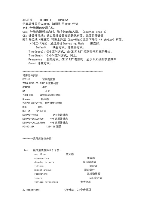
AD芯片-----TECHWELL TW6805A仿真软件里的AD0809有问题,用0808代替定时/计数器的使用方法:CLK:计数和测频状态时,数字波的输入端。
(counter enable)CE:计数使能端;通过属性设置高还是低有效。
无效暂停计数RST:复位端(RESET),可设上升沿(Low-High)或者下降沿(High-Low)有效。
4种工作方式:通过属性Operating Mode 来选择。
Default : 缺省方式,计数器方式。
Time(secs):100S定时方式,由CE和RST控制暂停和重新开始。
Time(hms):10小时定时方式,同上。
Frequency: 测频方式,CE和RST有效时,显示CLK端数字波频率Count:计数方式。
+++++++++++++++++++++++++++++++++++++++++++++++++++++++++++++常用元件列表:POT-HG 可调电位器7SEG-MPX8-CC-BLUE 8位数码管COMPIM 串口SW- 开关7SEG-BCD 含译码驱动的数显Speaker 扬声器2N5771和2N5772,15V对管300MARES , CAP,BUTTON 按钮开关KEYPAD-PHONE 3*4电话键盘KEYPAD-SMALLCALC 4*4计算器键盘KEYPAD-CALCULATOR 4*6计算器键盘PG160128A 128*128液晶++++++++元件库详细分类ics 模拟集成器件8个子类:amplifier 放大器comparators 比较器display drivers 显示驱动器filters 滤波器miscellaneous 混杂器件regulators 三端稳压器timers 555定时器voltage references 参考电压2,capacitors CAP电容,23个分类别animated 可显示充放电电荷电容audio grade axial 音响专用电容axial lead polypropene 径向轴引线聚丙烯电容axial lead polystyrene 径向轴引线聚苯乙烯电容ceramic disc 陶瓷圆片电容decoupling disc 解耦圆片电容high temp radial 高温径向电容high temp axial electrolytic高温径向电解电容metallised polyester film 金属聚酯膜电容metallised polypropene 金属聚丙烯电容metallised polypropene film 金属聚丙烯膜电容miniture electrolytic 微型电解电容multilayer metallised polyester film 多层金属聚酯膜电容mylar film 聚酯薄膜电容nickel barrier 镍栅电容non polarised 无极性电容polyester layer 聚酯层电容radial electrolytic 径向电解电容resin dipped 树脂蚀刻电容tantalum bead 钽珠电容variable 可变电容vx a xial electrolytic VX 轴电解电容3,CMOS 4000 series 4000系列数字电路adders 加法器buffers & drivers 缓冲和驱动器comparators 比较器counters 计数器decoders 译码器encoders 编码器flip-flops & latches 触发器和锁存器frequency dividers & tiner 分频和定时器gates & inverters 门电路和反相器memory 存储器混杂逻辑电路mutiplexers 数据选择器multivibrators 多谐振荡器phase-locked loops(PLL) 锁相环registers 寄存器signal switcher 信号开关4,connectors 接头;8个分类:audio 音频接头D-type D型接头DIL 双排插座header blocks 插头miscellaneous 各种接头PCB transfer PCB 传输接头SIL 单盘插座ribbon cable 蛇皮电缆terminal blocks 接线端子台5,data converters 数据转换器:4个分类:A/D converters 模数转换器D/A converters 数模转换器sample & hold 采样保持器temperature sensors 温度传感器6,debugging tools 调试工具数据:3个类别:breakpoint triggers 断点触发器logic probes 逻辑输出探针logic timuli 逻辑状态输入7,diodes 二极管;8个分类:bridge rectifiers 整流桥generic 普通二极管rectifiers 整流二极管schottky 肖特基二极管switching 开关二极管tunnel 隧道二极管varicap 稳压二极管8,inductors 电感:3个类别:generic 普通电感SMT inductors 表面安装技术电感transformers 变压器9,laplace primitives 拉普拉斯模型:7个类别:1st order 一阶模型2nd order 二阶模型controllers 控制器non-linear 非线性模型operators 算子poles/zeros 极点/零点symbols 符号10,memory ICs 存储器芯片:7个分类:dynamic RAM 动态数据存储器EEPROM 电可擦出程序存储器EPROM 可擦出程序存储器I2C memories I2C总线存储器memory cards 存储卡SPI Memories SPI总线存储器static RAM 静态数据存储器11,microprocessor ICs 微处理器:13个分类:12,modelling primitivvves 建模源:9个分类:13,operational amplifiers 运算放大器:7个分类:dual 双运放ideal 理想运放macromodel 大量使用的运放octal 8运放quad 4运放single 单运放triple 三运放14,optoelectronics 光电器件:11个分类:7-segment displays 7段显示alphanumeric LCDs 液晶数码显示bargraph displays 条形显示dot matrix displays 点阵显示graphical LCDs 液晶图形显示lamps 灯LCD controllers 液晶控制器LCD controllers 液晶面板显示LEDs 发光二极管optocouplers 光电耦合serial LCDs 串行液晶显示15,resistors 电阻:11个分类:metal film 金属膜电阻10 watt wirewound 10w绕线电阻2w metal film 2w 金属膜电阻3 watt wirewound 3w 绕线电阻7 watt wirewound 7w 绕线电阻generix 普通电阻high voltage 高压电阻NTC 负温度系数热敏电阻resistor packs 排阻variable 滑动变阻器varisitors可变电阻参考试验中采用的可变电阻是:POT-HG16,simulator primitives 仿真源:3个类别:flip-flops 触发器gates 门电路sources 电源17,switches and relays 开关和继电器:4个类别:key pads 键盘relays 普通继电器relays(specific) 专用继电器switches 开关18,switching devices 开关器件:4个分类:DIACs 两端交流开关generic 普通开关元件SCRs 可控硅TRIACs 三端双向可控硅19,真空管:20,传感器:2个分类:pressure 压力传感器temperature 温度传感器21,晶体管:8个分类:bipolar 双极型晶体管generic 普通晶体管(错误)IGBT 绝缘栅双极晶体管JFET 结型场效应管MOSFET 金属氧化物场效应管RF power LDMOS 射频功率LDMOS管RF power VDMOS 射频功率VDMOS管unijunction 单结晶体管Electromechanical 电机MOTOR AC 交流电机MOTOR SERVO 伺服电机双相步进电机motor-bistepper(Bipolar Stepper Motor),四相步进电机motor-stepper(unipolar stepper motor)驱动电路,用ULN2003可以,proteus中推荐的L298和L6201(电子元件-步进电机中有L298资料)+++++++++++++++++++++++++++++++++++++++++++++++++++++++++++++++++++++步进电机,可以用MTD2003,UN2916等专用芯片Proteus中图形液晶模块驱动芯片一览表LM3228 LM3229 LM3267 LM3283LM3287 LM4228 LM4265 LM4267LM4283 LM4287 PG12864F PG24064FPG128128A PG160128AAGM1232G EW12A03GLY HDM32GS12-B HDM32GS12Y-BHDG12864F-1 HDS12864F-3 HDG12864L-4 HDG12864L-6NOKIA7110 TG126410GFSB TG13650FEYAMPIRE128x64 LGM12641BS1RPROTEUS原理图元器件库详细说明单双向可控硅、包括电阻、电容、二极管、三极管和PCB的连接器符号、包括虚拟仪器和有源器件、拨动开关、键盘、可调电位器和开关、包括二极管和整流桥、稳压管、变容二极管、大功率二极管、高速二极管、可控硅、包括LCD、LED、LED阵列包括三极管包括场效应管包括模拟元器件AS 稳压二极管、全桥、74系列、及其他。
IRF7241中文资料
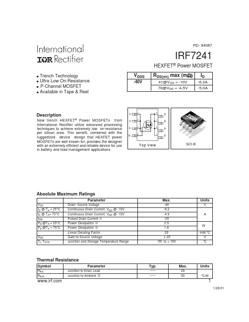
元器件交易网
IRF7241
C, Capacitance(pF)
5000
4000
Ciss
3000
VGS = 0V, f = 1 MHZ Ciss = Cgs + Cgd, Cds SHORTED Crss = Cgd Coss = Cds + Cgd
2000
1000 Coss
Parameter V(BR)DSS Drain-to-Source Breakdown Voltage ∆V(BR)DSS/∆TJ Breakdown Voltage Temp. Coefficient
RDS(on)
Static Drain-to-Source On-Resistance
VGS(th) gfs
1000 100
VGS TOP -15V
-10V -4.5V -3.7V -3.5V
-3.3V -3.0V BOTTOM -2.7V
10
1
0.1
0.01 0.1
-2.70V
20µs PULSE WIDTH TJ = 25 °C
1
10
100
-VDS, Drain-to-Source Voltage (V)
100.00
10.00
TJ = 150°C
2.0 ID = -6.2A 1.5
-ID, Drain-to-Source Current (Α)
1.00
0.10
0.01 2.5
TJ = 25°C
VDS = -25V 20µs PULSE WIDTH
3.0
3.5
4.0
4.5
5.0
-VGS, Gate-to-Source Voltage (V)
SQ71系列安全入门套件用户手册说明书

SQ71 Series Secure Starter Kit使用手册目录1.变更历程 (3)2.使用环境 (4)3.Starter Kit介紹 (5)3.1硬件外观 (5)3.2Block Diagram (7)4.StarterKit软件安装 (8)4.1软件安装程序 (8)4.2软件启动 (12)5.StarterKit软件功能说明 (15)5.1 软件简介 (15)5.2 StarterKit 主界面 (15)5.2.1 指令建构区(Build Command) (16)5.2.2 工具栏(Tools Bar) (17)5.2.3 状态栏(Status Bar) (21)5.2.4 传输纪录区(Log) (23)5.2.5 AES-256 支援 (24)5.3存储器映像窗口(Memory) (26)5.3.1 存储器配置区段 (28)5.3.2 配置选单 (29)5.3.3 工具栏(Tool Bar) (32)5.4装置烧录窗口(Program Device) (37)5.4.1 存储器配置区段 (39)5.4.2 功能选项 (44)5.4.3 工具栏(Tools Bar) (49)5.4.4 Log Window (53)6.移除SQ71_Series_StarterKit (Uninstall) (55)1.变更历程Version ApprovedDateDescriptionV1.3 2022/1/12 1.更新「CH. 2 使用环境」2.新增「CH.5.2.1 指令建构区」注3V1.2 2021/6/11 1.更新「CH3. Starter Kit介绍」内容,硬件更新2.更新「CH4.2 软件启动」,Select Device 接口3.新增「CH5.4 装置烧录窗口」内容V1.1 2021/03/11 1.「CH3.1 硬件外观」新增叙述与图3.22.「CH4.2 软件启动」,新增更换Adapter Board 上IC相关备注V1.0 2021/01/15 首次发行2.使用环境在使用SQ71 Series Starter Kit之前,需先准备下面几个项目,并确认计算机之系统规格。
数控铣床毕业论文

数控铣床毕业论文 Last revised by LE LE in 2021毕业论文课题:数控加工中心孔类零件加工专业:加工中心姓名:指导老师:完成日期:目录内容摘要 (3)正文 (3)1. 盘类零件加工工艺性分析 (3)选择并确定数控加工中心加工盘类零件 (3)盘类零件图样的工艺性分析 (4)盘类零件的加工路线 (5)2. 盘类零件加工工艺的确定 (6)工艺分析 (6)工艺卡片 (7)刀具卡片 (8)走刀路线 (8)程序的编制 (13)3. 误差分析 (17)4. 结论 (17)参考文献 (18)盘类零件的加工内容摘要盘类零件是由多个端面、深孔、螺纹孔、曲面、沟槽、外轮廓组合而成的较复杂的盘形零件。
其特点是零件基本形状呈盘形块状,零件表面汇集了多种典型表面。
加工时,装夹次数一般较少,但所用刀具一般较多,编制程序较繁琐。
加工前需要做好充分的准备,包括图纸分析、确定加工工艺、选用机床型号、选用毛坯大小、确定走刀路线与加工顺序等,其前期的准备工作比较复杂。
关键词:盘类零件图纸分析确定加工工艺机床正文:数控加工过程中需要考虑多方面的因素,包括图纸的分析、选择适合加工该零件的数控机床、选择加工中将要用到的刀具规格、选择良好的切削用量等等。
由此看出,数控加工实践是一门复杂的技术。
需要多学习、多熟练才能在保证安全的情况下完成任务。
所以,我作为数控行业的一份子要努力的提高自身的专业水平,不断的锻炼自己的实践技能,成为一个全方面发展的数控技术人才。
1盘类零件加工的工艺性分析盘类零件加工工艺性分析是编程前的重要工艺准备工作之一,根据实际加工,利用数控加工中心具有高精度、高柔性、高效率,且适合加工具有复杂轮廓、端面的零件等特点。
通过对使用BV75型数控加工中心加工盘类零件,来阐述以下几个方面的问题:1.1选择并确定数控加工中心加工盘类零件在选择加工盘类零件的设备时,应充分发挥数控加工中心适用于加工复杂端面这一加工优势。
H11J1G中文资料
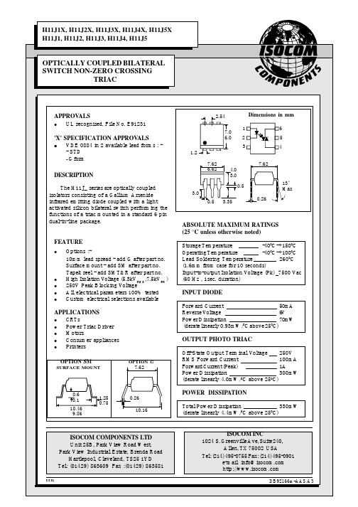
Normalised Repetitive Peak Off-state Voltage vs. Ambient Temperature
RMS on-state current I T (Arms)
0.1
0.05
Normalised to TA = 25°C
0 -30 0 25 50 75 100 125 Ambient temperature TA ( °C ) Forward Current vs. Ambient Temperature 80 70 Forward current I F (mA) 60 50 40 30 20 10 0 -30 0 25 50 75 100 125 Ambient temperature TA ( °C ) Normalised Input Trigger Current vs. Ambient Temperature 1.4 1.2 1.0 0.8 0.6 0.4 0.2 0 -30 0 25 50 75 100 Ambient temperature TA ( °C )
8/8/01
ISOCOM INC 1024 S. Greenville Ave, Suite 240, Allen, TX 75002 USA Tel: (214) 495-0755 Fax: (214) 495-0901 e-mail info@
DB92166m-AAS/A3
元器件交易网
ELECTRICAL CHARACTERISTICS ( TA = 25°C Unless otherwise noted ) PARAMETER Input Forward Voltage (VF) Reverse Current (IR) Peak Off-state Current ( IDRM ) Peak Blocking Voltage ( VDRM ) On-state Voltage ( VTM ) Critical rate of rise of off-state Voltage ( dv/dt ) ( note 1 ) Critical rate of rise of commutating Voltage ( dv/dt ) ( note 1 ) 250 1.5 10 0.1 0.2 3.0 MIN TYP MAX UNITS 1.2 1.5 100 100 V µA nA V V V/µs V/µs I load = 15mA, VIN = 30V ( fig 1. ) TEST CONDITION IF = 10mA VR = 6V VDRM = 250V (note 1 ) IDRM = 100nA ITM = 100mA ( peak )
S07J中文资料

V OHHigh-level output voltage VSN54LS07SN54LS07, SN74LS07, SN74LS17HEX BUFFERS/DRIVERS WITHOPEN-COLLECTOR HIGH-VOLTAGE OUTPUTS元器件交易网I OH V OLV CC = MIN,V IL = 0.8 VV CC = MIN,V IH = 2 V VmA SN54LS07PARAMETERTEST CONDITIONS MIN TYP MAX UNIT AYR L = 110 Ω,C L = 15 pFnsSN54LS07, SN74LS07, SN74LS17HEX BUFFERS/DRIVERS WITHOPEN-COLLECTOR HIGH-VOLTAGE OUTPUTS元器件交易网元器件交易网IMPORTANT NOTICETexas Instruments and its subsidiaries (TI) reserve the right to make changes to their products or to discontinueany product or service without notice, and advise customers to obtain the latest version of relevant informationto verify, before placing orders, that information being relied on is current and complete. All products are soldsubject to the terms and conditions of sale supplied at the time of order acknowledgement, including thosepertaining to warranty, patent infringement, and limitation of liability.TI warrants performance of its semiconductor products to the specifications applicable at the time of sale inaccordance with TI’s standard warranty. Testing and other quality control techniques are utilized to the extentTI deems necessary to support this warranty. Specific testing of all parameters of each device is not necessarilyperformed, except those mandated by government requirements.CERTAIN APPLICATIONS USING SEMICONDUCTOR PRODUCTS MAY INVOLVE POTENTIAL RISKS OFDEATH, PERSONAL INJURY, OR SEVERE PROPERTY OR ENVIRONMENTAL DAMAGE (“CRITICALAPPLICATIONS”). TI SEMICONDUCTOR PRODUCTS ARE NOT DESIGNED, AUTHORIZED, ORWARRANTED TO BE SUITABLE FOR USE IN LIFE-SUPPORT DEVICES OR SYSTEMS OR OTHERCRITICAL APPLICATIONS. INCLUSION OF TI PRODUCTS IN SUCH APPLICATIONS IS UNDERSTOOD TOBE FULLY AT THE CUSTOMER’S RISK.In order to minimize risks associated with the customer’s applications, adequate design and operatingsafeguards must be provided by the customer to minimize inherent or procedural hazards.TI assumes no liability for applications assistance or customer product design. TI does not warrant or representthat any license, either express or implied, is granted under any patent right, copyright, mask work right, or otherintellectual property right of TI covering or relating to any combination, machine, or process in which suchsemiconductor products or services might be or are used. TI’s publication of information regarding any thirdparty’s products or services does not constitute TI’s approval, warranty or endorsement thereof.Copyright © 1998, Texas Instruments Incorporated。
菲尼克斯电气开关电源中文样本
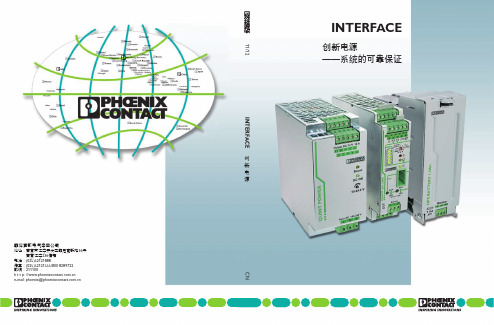
INTERFACE创新电源——系统的可靠保证菲尼克斯电气中国公司地址:南京市江宁开发区菲尼克斯路36号南京江宁236信箱电话:(025)52121888传真:(025)52121555/800 8289722邮编:211100h t t p: //e-mail: phoenix@ CN 11/12 INTERFACE 创新电源TNR 5768710/10.2011-01 Printed In China© PHOENIX CONTACT2011突破性技术——电源解决方案创新促进发展。
菲尼克斯电气的电源产品无疑印证了这一宗旨。
在对理想的电源探索中,我们洞悉市场,与客户密切合作,坚持与执着,不断创造出卓越的新产品技术。
我们的目标是最大程度提高您的设备和系统的可用性。
QUINT电源提供最优产品功能,三个新产品系列在各自领域里树立了新的标杆。
新产品采用ACB技术的冗余模块ACB(自动电流平衡)技术可使您的冗余电源系统的使用寿命翻倍。
该技术确保一定范围内所有的电源平衡输出。
QUINT ORING冗余模块的ACB技术还可检测临界工作状态,并为您提供提前预警。
新产品采用IQ技术的不间断电源具有持续电池监控和智能管理功能的IQ技术可随时为您提供电池的充电状态、剩余工作时间和使用寿命等相关信息。
智能通信功能将预警您危险工况的出现。
这可减少维护工作量,提升系统可用性。
新产品采用SFB技术的DC/DC变换器SFB(选择性触发)技术可在一旦输出回路出现短路时,可靠地切断故障回路。
在短路情况下,将能提供6倍额定输出电流,维持12ms时间。
因此,SFB技术能够可靠地触发标准断路器。
您可快速地进行故障定位,并确保系统的重要设备继续工作。
——采用SFB技术为系统有效性提供最高保证新一代紧凑型QUINT电源,将最大程度地保证系统的有效性。
该电源采用SFB技术(选择性触发技术),能在12ms内输出6倍的额定电流,可靠快速地触发标准断路器脱扣。
74LS01中文资料
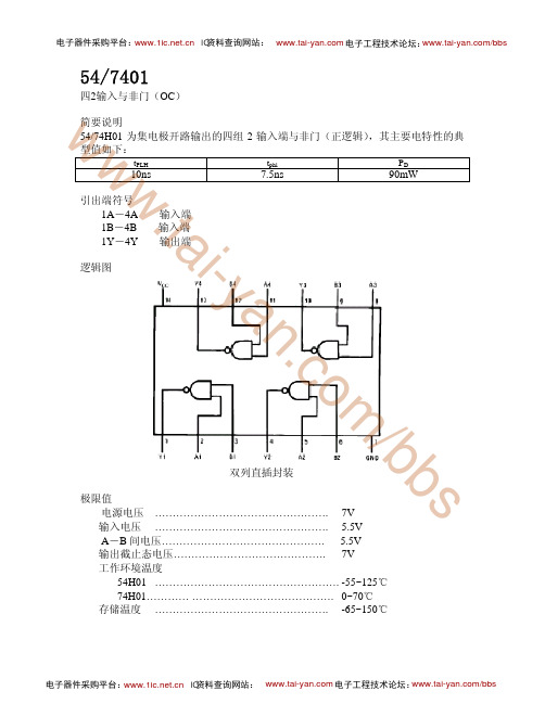
测试条件 Vcc =5V,CL=25Pf ,RL=280Ω
‘H01 最大 15 12
单位
ns ns
电子器件采购平台: IC资料查询网站: 电子工程技术论坛:/bbs
输出低电平电流IOL
最小
4.5 4.75
2
54H01/74H01 额定
5 5
最大 5.5 5.25
0.8 5.5V 20
an 静态特性(TA 为工作环境温度范围)
参数
测 试 条 件【1】
.c VIK输入嵌位电压 o IO(OFF)输出截止态电流
VOL输出低电平电压
m II最大输入电压时输入电流 IIH输入高电平电流 IIL输入低电平电流
输出截止态电压……………………………………. 7V
工作环境温度
54H01 ……………………………………………. -55~125℃
74H01………… …………………………………. 0~70℃
存储温度 …………………………………………. -65~150℃
电子器件采购平台: IC资料查询网站: 电子工程技术论坛:/bbs
电子器件采购平台: IC资料查询网站: 电子工程技术论坛:/bbs
功能表:
www 推荐工作条件:
.ta 电源电压 VCC
54
74
i 输入高电平电压ViH
- 输入低电平电压ViL
y 输出截止态电压 VO(OFF)
tPLH
w 10ns
tphl
7.5ns
PD
90mW
w 引出端符号 1A-4A . 1B-4B t 1Y-4Y
输入端 输入端 输出端
ai 逻辑图
/bbs 极限值
双列直插封装
1PH7电机参数
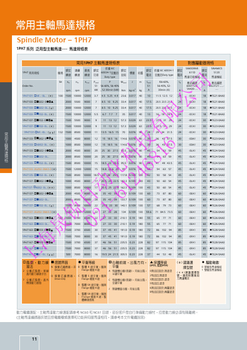
1PH7133- £ND02- 0L.. (*)
1000 8500 10000 12 15 18.5 16 114.6 0.076 90 30 36 43 37.5 30
技 6 1PH7133- £¢G02- 0ò§p
2000 4500 8000 20 25 30 27.5 95.5 0.076 90 45 54 63 59
60
自 - 1PH7137- £¢F02- 0L.. (*)
1500 8500 10000 22 27.5 33 30 140.1 0.109 130 57 68 79 73
60
1PH7137- 2GZ02- 0MJ3-Z (*)
1500 12000 12000 22 27 33 28 134 0.109 130 59.6 71 84.5 73.5 60
ø 驅動軸數
0 單軸型馬達模組 1 雙軸型馬達模組
動力電纜選配:主軸馬達動力線選配請參考 NC60 和 NC61 目錄。部份客戶是自行準備動力線材,但是動力線必須有隔離網。 (主軸馬達編碼器訊號回授電纜種類選擇和功能與伺服馬達相同,請參考本文件電纜說明)
11
常用伺服馬達規格
Servo Motor –1FK7 Compact
1 1PH7163- £¢D03- 0ò§p 160 1000 3700 6500 22 27 33 30 210.1 0.19 180 55 65 77 71
60
锐 2 1PH7163- £¢D03- 0L..
1000 7000 8000 22 27 33 30 210.1 0.19 180 55 65 77 71
電流 定義的Duty type
SIMODRIVE
額定
ISIS7原件汉英对照
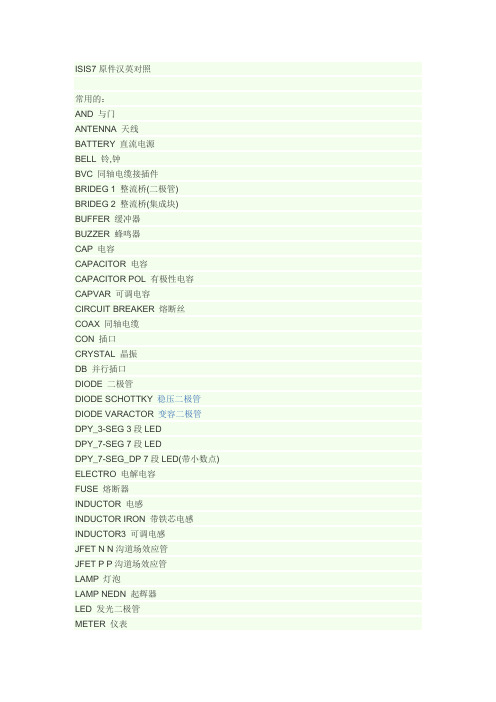
ISIS7原件汉英对照常用的:AND 与门ANTENNA 天线BATTERY 直流电源BELL 铃,钟BVC 同轴电缆接插件BRIDEG 1 整流桥(二极管)BRIDEG 2 整流桥(集成块) BUFFER 缓冲器BUZZER 蜂鸣器CAP 电容CAPACITOR 电容CAPACITOR POL 有极性电容CAPVAR 可调电容CIRCUIT BREAKER 熔断丝COAX 同轴电缆CON 插口CRYSTAL 晶振DB 并行插口DIODE 二极管DIODE SCHOTTKY 稳压二极管DIODE VARACTOR 变容二极管DPY_3-SEG 3段LEDDPY_7-SEG 7段LEDDPY_7-SEG_DP 7段LED(带小数点) ELECTRO 电解电容FUSE 熔断器INDUCTOR 电感INDUCTOR IRON 带铁芯电感INDUCTOR3 可调电感JFET N N沟道场效应管JFET P P沟道场效应管LAMP 灯泡LAMP NEDN 起辉器LED 发光二极管METER 仪表MICROPHONE 麦克风MOSFET MOS管MOTOR AC 交流电机MOTOR SERVO 伺服电机NAND 与非门NOR 或非门NOT 非门NPN NPN三极管NPN-PHOTO 感光三极管OPAMP 运放OR 或门PHOTO 感光二极管PNP 三极管NPN DAR NPN三极管PNP DAR PNP三极管POT 滑线变阻器PELAY-DPDT 双刀双掷继电器RES1.2 电阻RES3.4 可变电阻RESISTOR BRIDGE ? 桥式电阻RESPACK ? 电阻SCR 晶闸管PLUG ? 插头PLUG AC FEMALE 三相交流插头SOCKET ? 插座SOURCE CURRENT 电流源SOURCE VOLTAGE 电压源SPEAKER 扬声器SW ? 开关SWITCH ?SW-DPDY ? 双刀双掷开关SW-SPST ? 单刀单掷开关SW-PB 按钮THERMISTOR 电热调节器TRANS1 变压器TRANS2 可调变压器TRIAC ? 三端双向可控硅TRIODE ? 三极真空管VARISTOR 变阻器ZENER ? 齐纳二极管DPY_7-SEG_DP 数码管SW-PB 开关7407 驱动门1N914 二极管74Ls00 与非门74LS04 非门74LS08 与门74LS390 TTL 双十进制计数器7SEG 4针BCD-LED 输出从0-9 对应于4根线的BCD码7SEG 3-8译码器电路BCD-7SEG转换电路ALTERNATOR 交流发电机AMMETER-MILLI mA安培计AND 与门BATTERY 电池/电池组BUS 总线CAP 电容CAPACITOR 电容器CLOCK 时钟信号源CRYSTAL 晶振D-FLIPFLOP D触发器FUSE 保险丝GROUND 地LAMP 灯LED-RED 红色发光二极管LM016L 2行16列液晶可显示2行16列英文字符,有8位数据总线D0-D7,RS,R/W,EN三个控制端口(共14线),工作电压为5V。
H11L1S(TA),H11L1S(TA),H11L1S(TA),H11L1M,H11L1,H11L2M,H11L2,H11L3M, 规格书,Datasheet 资料
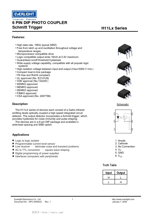
Schmitt TriggerH11Lx SeriesFeatures:• High data rate, 1MHz typical (NRZ)• Free from latch up and oscilliation throughout voltage and temperature ranges.• Microprocessor compatible drive• Logic compatible output sinks 16mA at 0.4V maximum • Guaranteed on/off threshold hysteresis• Wide supply voltage capability, compatible with all popular logic systems• High isolation voltage between input and output (Viso=5000 V rms ) • Compact dual-in-line package • Pb free and RoHS compliant. • UL approved (No. E214129) • VDE approval (No.132249 ) • SEMKO approved • NEMKO approved • DEMKO approved• FIMKO approved• CSA approved (No. 2007798)SchematicDescriptionThe H11LX series of devices each consist of a GaAs infrared emitting diode optically coupled a high speed integrated circuit detector. The output detector incorporates a Schmitt trigger, which provides hysteresis for noise immunity and pulse shaping. The devices are in a 6-pin DIP package and available in wide-lead spacing and SMD option.Applications1. Anode2. Cathode3. No Connection4. V O5. GND6. V CCz Logic to logic isolatorz Programmable current level sensorz Line receiver - eliminate noise and transient problems z AC to TTL conversion - square wave shaping z Digital programming of power supplies z Interfaces computers with peripheralsTruth TableInput Output H L L HSchmitt Trigger H11Lx SeriesAbsolute Maximum Ratings (T a =25°C)Parameter Symbol Rating Unit Forward currentI F 60 mA Reverse voltage V R 6 V InputPower dissipation P D 120 mW V 45 Allowed RangeV o 0 to 16 V V 65 Allowed Range V CC3 to 16VOutput Current I 0 50 mA Outputpower dissipationP D 150 mW Total power dissipation P tot 250 mW Isolation voltage *1 V iso 5000 V rms Operating temperature T opr -55~+100 °C Storage temperature T stg -55~+150 °C Soldering temperature *2 T sol260 °CNotes*1 AC for 1 minute, R.H.= 40 ~ 60% R.H. In this test, pins 1, 2 & 3 are shorted together, and pins 4, 5 & 6 are shorted together. *2 For 10 seconds.Schmitt Trigger H11Lx SeriesElectrical Characteristics (T a =25°C unless specified otherwise)InputParameter Symbol Min. Typ.* Max. Unit ConditionForward voltageV F - 1.15 1.5 V I F = 10mA Reverse Leakage current I R - - 10 µA V R = 5VCapacitanceC J- - 100 pF V=0, f=1MHzOutputParameter Symbol Min. Typ.* Max. Unit ConditionOperation Voltage Range V CC 3 - 15 V Supply Current I CC(off) - 1.6 5 mA I F =0mA, Vcc=5V Output Current, High I OH- - 100 µA I F =0mA, Vcc=Vo=15VIsolation ResistanceR ISO 1011- -Ω V I-O =500VDCTransfer CharacteristicsParameter Symbol Min. Typ.* Max. Unit ConditionSupply Current I CC(on) - 1.6 5 mA I F =10mA, Vcc=5V Output Voltage .lowV OL- - 0.4 VVcc=5V, I F =I Fon (max.), R L =270ΩH11L1 - -1.6 H11L2 - - 10Turn on ThresholdCurrent 1H11L3I Fon- - 5 mA Vcc=5V, R L =270Ω Turn off Threshold Current I Foff - 1 - mA Vcc=5V, R L =270Ω Hysteresis Ratio I Fon /I Foff 0.5 - 0.9 Vcc=5V, R L =270ΩTurn on Time t on - - 4 μS Fall Time t r - 0.1 - μS Turn off Time t off - - 4 μS Rise Time t r - 0.1 - μS Vcc=5V, I F =I Fon , R L =270ΩData Rate- 1 - MHz* Typical values at T a = 25°C 1. Max. I F(ON) is the maximum current required to trigger the output. For examples, a 1.6mA maximum trigger current would require the LED to be driven at a current greater than 1.6mA to guarantee the device will turn on. A 10% guard band is recommended to account for degradation of the LED over its lifetime. The maximum allowable LED drive current is 60mA.Schmitt TriggerH11Lx SeriesTypical Performance CurvesSchmitt TriggerH11Lx SeriesOrder InformationPart NumberH11LXY(Z)-VNoteX = Part No. for 1, 2 or 3Y = Lead form option (S, S1, M or none)Z = Tape and reel option (TA, TB or none).V = VDE (optional)quantity Option Description PackingNone Standard DIP-6 65 units per tubeM Wide lead bend (0.4 inch spacing) 65 units per tubeS + TA Surface mount lead form + TA tape & reel option 1000 units per reelS + TB Surface mount lead form + TB tape & reel option 1000 units per reelS1 + TA Surface mount lead form (low profile) + TA tape & reel option 1000 units per reelS1 + TB Surface mount lead form (low profile) + TB tape & reel option 1000 units per reelSchmitt Trigger H11Lx SeriesPackage Drawings(Dimensions in mm)Standard DIP TypeOption M TypeSchmitt Trigger H11Lx Seriesption S1 TypeOSchmitt Trigger H11Lx Series Recommended pad layout for surface mount leadformevice Markingotesdenotes EverlightberDELH11L3YW WVNLEH11L3 denotes Device NumY denotes 1 digit Year codeWW denotes 2 digit Week codeV denotes VDE (optional)Schmitt Trigger H11Lx SeriesTape & Reel Packing Specificationsape dimensionsE FTDimension No. A B Do D1 Dimension (mm)10.4±0.1 7.52±0.1 1.5±0.1 1.5+0.1/-0 1.75±0.1 7.5±0.1Dimension No. Po P1 P2 tW KDimension (mm)4.0±0.15 1.6±0.1 2.0±0.1 0.35±0.03 16.0±0.2 4.5±0.1Schmitt Trigger H11Lx Series Solder Reflow Temperature ProfileTIME (S)6 PIN DIP PHOTO COUPLERSchmitt Trigger Everlight Electronics Co., Ltd. 11 Document No :DPC-0000022 Rev. 1 January 7, 2009H11Lx Series DISCLAIMERThe specifications in this datasheet may be changed without notice. EVERLIGHT reserves the authority . When using this product, please observe the absolute maximum ratings and the instructions for use as the 3. hese specification sheets include materials protected under copyright of EVERLIGHT. Reproduction in1.on material change for above specification.2outlined in this datasheet. EVERLIGHT assumes no responsibility for any damage resulting from use of product which does not comply with the absolute maximum ratings and the instructions included in this datasheet.T any form is prohibited without the specific consent of EVERLIGHT.芯天下--/。
S107-S资料
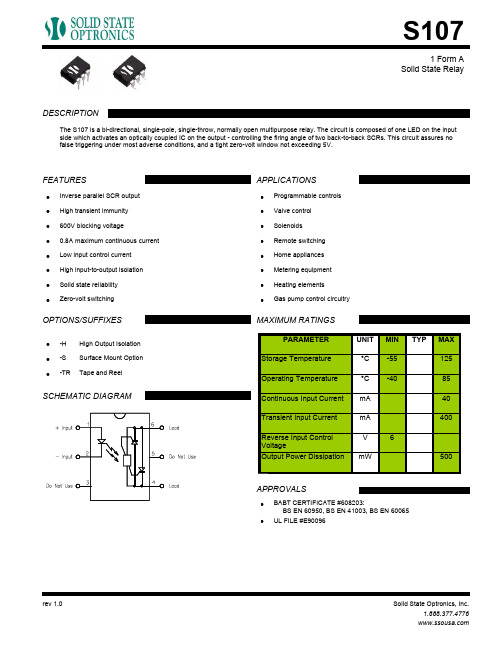
Solid State RelayThe S107 is a bi-directional, single-pole, single-throw, normally open multipurpose relay. The circuit is composed of one LED on the input side which activates an optically coupled IC on the output - controlling the firing angle of two back-to-back SCRs. This circuit assures no false triggering under most adverse conditions, and a tight zero-volt window not exceeding 5V.DESCRIPTIONFEATURES APPLICATIONSOPTIONS/SUFFIXES SCHEMATIC DIAGRAMMAXIMUM RATINGSAPPROVALSInverse parallel SCR output • High transient immunity • 600V blocking voltage• 0.8A maximum continuous current • Low input control current • High input-to-output isolation • Solid state reliability • Zero-volt switching•Programmable controls •Valve control •Solenoids •Remote switching •Home appliances •Metering equipment •Heating elements •Gas pump control circuitry•High Output Isolation • -H Surface Mount Option • -S Tape and Reel•-TRPARAMETER UNIT MIN TYPMAX Storage Temperature °C -55125Operating Temperature °C -4085Continuous Input Current mA 40Transient Input Current mA 400Reverse Input Control VoltageV 6Output Power DissipationmW500BABT CERTIFICATE #608203:BS EN 60950, BS EN 41003, BS EN 60065•UL FILE #E90096•Solid State RelayELECTRICAL CHARACTERISTICS - 25°PARAMETER UNIT MIN TYP MAX TEST CONDITIONSINPUT SPECIFICATIONSLED Forward Voltage V 1.2 1.5If = 10mALED Reverse Voltage V612Ir = 10uAMust Operate Current m5 2.5Io = 0.8A, resistive loadAJunction Capacitance p5Vf = 0VFOUTPUT SPECIFICATIONSBlocking Voltage V600Io = 600uAContinuous Load Current A0.8If = 5mASurge Current Rating A5T = 10usHolding Current m10AOn-Voltage V 1.2Io = 0.8AVoltage Across Load at Turn-On V5If = 5mALeakage Currentµ100250Vo = 250VAThermal Resistance°150C/Power Factor0.3Critical Rate of Rise (dV/dt)V400/µsCOUPLED SPECIFICATIONSIsolation Voltage V2500T = 1 minute-H Suffix V3750T = 1 minuteIsolation Resistance G100ΩCoupled Capacitance p6FSolid State RelayPERFORMANCE DATAThis solid state relay has been designed with a driver circuit that controls the operation of two back-to-back silicon controlled rectifiers (SCRs), each responsible for one half of the AC cycle. If an AC signal is examined, the turn on, turn off and zero-volt switching can be seen. Figure 1 shows a typical 60 Hz, 120Vac signal with a corresponding relay input signal:ZERO-VOLT SWITCHINGFigure 1 shows the sequence of zero-volt switching operation. At Stage 1, an input signal is applied to the relay. The relay will not turn on until the threshold voltage of 5V is reached. Once this point is reached (Stage 2), SCR #1 (designated as the SCR which controls positive AC voltage) turns on. However, SCR #1 only conducts for an instant, as the cycle quickly crosses zero. At this point (Stage 3), SCR #1 will turn off and SCR #2 (negative AC voltage) turns on. Likewise, at the next zero cross (Stage 4), SCR #2 will turn off and SCR #1 conducts again. Even though the input signal is terminated at Stage 5, the relay will continue to conduct (typical SCR behavior) until Stage 6, when SCR #1 crosses zero and ceases to conduct. Please note that turn on can likewise begin on the negative phase of the AC cycle with a -5V threshold, though only the positive phase is shown here.Solid State RelayMECHANICAL DIMENSIONS6 PIN DUAL IN-LINE PACKAGE 6 PIN SURFACE MOUNT DEVICEEND VIEW END VIEWTOP VIEW TOP VIEWBOTTOM VIEW/ BOARD PATTERNBOTTOM VIEW/ BOARD PATTERN。
飞利浦107S41型彩显电源工作原理分析 第3页
3、高压调整
该机的高压调整(B+电压调整)不是采用电位器调整方式,而是采用微处理器调整方式。当需要降低显像管高压时,7801的B+电压调整端29脚输出的控制信号的占空比增大,通过3858、2820低通滤波获得的直流电压增大。该电压通过3561使7501⑤脚输入的电压增大。7501⑤脚输入的电压增大后,B+电源输出的电压会减小,使显像管高压相应减小,实现高压调整的目的。反之,调整过程相反。
4、行频失锁控制
开机瞬间或显示模式变换瞬间,7501内的行振荡器产生的行频脉冲与同步信号不能及时同步时,750t的17脚输出高电平行频失锁控制电压。该电压通过38t8送到7801的18脚,经3544使7506导通,通过6515、6517、3545使7501的③脚变为低电平。由于③脚是B+电源的误差放大器输出端,所以③脚为低电平后,它的⑥脚不能输出开关管激励脉冲。B+电源电路不能工作;当行振荡器产生的振荡频率与同步信号同步后,17脚变为低电平,不影响7501③脚电位,B+电源开始工作,实现行频失锁/锁定控制。
飞利浦107S41型彩显
本文评论 查看全部评论 (0) 表情: 姓名: 匿名 字数
点评:
同意评论声明 请登录 评论声明
尊重网上道德,遵守中华人民共和国的各项有关法律法规
3联想LXB-HF769A型17英
3脉冲变压器隔离的自激
3用电源厚膜电路
3用电源控制芯片L5991构
- 1、下载文档前请自行甄别文档内容的完整性,平台不提供额外的编辑、内容补充、找答案等附加服务。
- 2、"仅部分预览"的文档,不可在线预览部分如存在完整性等问题,可反馈申请退款(可完整预览的文档不适用该条件!)。
- 3、如文档侵犯您的权益,请联系客服反馈,我们会尽快为您处理(人工客服工作时间:9:00-18:30)。
ECR2104-H
View of the terminals (bottom view)
30 .118 (3.0)
Mounting holes (bottom view)
.150 (3.8)
.150 (3.8)
2 x .086 (2.18) 86 87 .150 (3.8) .150 (3.8) .706 .331 (17.9) (8.4)
Plug-in relays Mini ISO relays
VF7
Dimensional drawing Dust cover with quick connect terminals
.165 MAX. (4.2) 1.04 MAX. (26.5) .59 (15.0)
.236 (6.0)
1.04 MAX. (26.5) ø .209 (5.3)
Coil data
Available for nominal voltages Nominal coil resistance Resistor parallel to coil1) Nominal power consumption Test voltage winding/contact and contact/contact Ambient temperature range 2) Upper limit temperature for the coil Max. switching rate without current Operate time3) Release time4)
Accessories
Connectors see page 519
392
All specifications subject to change. Consult Tyco Electronics AMP GmbH for latest specifications.
Plug-in relays Mini ISO relays
30 .705 (17.9)
85 87
86
.331 (8.4)
.661 (16.8)
.118 (3.0)
PCB terminals
1.04 MAX. (26.5) 1.04 MAX. (26.5)
.992 MAX. (25.2) .118 (3.0) .059 (1.5) TIN PLATED .150 (3.8)
.630 ±.020 (16 ±0.5)
.98 ±.012 (24.9 ±0.3)
.669 +.039/-.020 (17 +1/-0.5)
.433 ±.020 (11 ±0.5) ø .067 +.008 (ø 1.7 +0.2) .248 ±.004 (6.3 ±0.1) .374 ±.004 (9.5 ±0.1) .047 ±.002 (1.2 ±0.05)
Load limit curve
ECR0629-N
Load limit curve 2 ^ safe shutdown, = no stationary arc (make contact)
Pin assignment
1 make contact/ 1 form A
Models with resistor or diode in parallel to the coil on request.
Max. switching rate at nominal load
1) 2)
The values apply to a resistive load or inductive load with suitable spark suppression at 14 VDC load voltage. This current may flow for a maximum of 3 sec for a make/break ratio 1 : 10.
ECR2105-Q
85
.335 (8.5) .669 (17.0)
2 x .076 (1.93)
394
All specifications subject to change. Consult Tyco Electronics AMP GmbH for latest specifications.
Plug-in relays Mini ISO relays
1) 2)
6 VDC Power F7 18 Ω - / 180 Ω 2.0/2.2 W
12 VDC Power VF7 91 Ω 1.6 W Power VF7 Power F7 72 Ω 332 Ω -/680 Ω 2.0/2.2 W 1.7 W 500 VACrms – 40 to + 125 °C 180 °C 20 Hz Typ. 7 msec Typ. 2 msec
See load limit curve See load limit curve Tested: USA 120 A / Europe up to 240 A 70 A 70 A 50 A 1 A at 12 VDC Typ. 70 mV/200 mV max. Typ. 2 °C > 107 operations For resistive load of 70 A, 1 sec make, 1 sec break time, 13.5 V switching voltage, 23 °C > 105 operations 6 operations per minute (0.1 Hz)
Typical applications
– Rear window defogger – Battery disconnection – Power distribution (clamp 15)
Car Industry
Truck Industry
Other Industry
134_kop2
Design
at 23 °C at 85 °C
Min. recommended current Voltage drop (initial) at 70 A, Increase in coil temperature at 10 A load Mechanical endurance (without load) Electrical endurance
Plug-in relays Mini ISO relays
Power relay F7 / VF7
Powertrain Systems
Chassis Systems
Safety
Security
Body
Driver Information
Convenience
Features
– Limiting continuous current 70 A – Dimensional characteristics and the functional allocation of the plug-in terminals to ISO 7588 – Standardized dimensions – 24 V versions with contact gap > 0.8 mm on request - Plug-in or PCB terminals
Conditions
All parametric, environmental and endurance tests are performed according to EIA Standard RS-407-A at standard test conditions unless otherwise noted: 23 °C ambient temperature, 20-50% RH, 29.5 ± 1.0" Hg (998.9 ±33.9 hPa).
.630 (16.0)
.992 MAX. (25.2) .453 MAX. (11.5)
.709 MAX. (18.0) 2 x .032 (0.8) .375 (9.5) .375 (9.5) .250 (6.3) 2 x .047 (1.2)
ECR2103-9
View of the terminals (bottom view)
ECR1098-Y
.031 ±.002 (0.8 ±0.05) Quick connect terminal similar to ISO 8092-1
View of the terminals (bottom view)
393
All specifications subject to change. Consult Tyco Electronics AMP GmbH for latest specifications.
Power reling
1.020 ±.012 (25.9 ±0.3) .236 ±.016 (6 ±0.4) .591 ±.004 (15 ±0.1) .209 ±.004 (5.3 ±0.1) .157 ±.008 (4 ±0.2) 1.020 ±.012 (25.9 ±0.3)
395
All specifications subject to change. Consult Tyco Electronics AMP GmbH for latest specifications.
Plug-in relays Mini ISO relays
Power relay F7 / VF7
Weight
Approx. 1.3 oz. (38 g)
Nominal voltage
6 V, 12 V or 24 V; other nominal voltages available on request
Terminals
