MiCOM P12y使用说明书
MiCOM P12y 定值清单及说明(1.C)
时间 Time
N.A
XX:XX:XX
XX:XX:XX
配置 CONFIGURATION
通用选项 General Options
接法 VT Connection VT
N.A.
N.A.
3Vpn
默认显示 Default Display
IN
默认显示 Default Display
IA
IA
互感器变比 Transfo. Ratio
R/W 0.01 Ien
读/写
R/W 0.01 Ien
读/写
R/W 0.01 Ien
读/写
8 Ien 8 Ien 8 Ien
0.005 Ien 0.005 Ien 0.005 Ien
R/W 0.1 Ien
读/写
R/W 0.5 Ien
读/写
25 Ien 40 Ien
0.01 Ien 0.01 Ien
M上i海COAMREPV1A2y电系力列自动化有限公司
缺省值
P125
P126
P127
E/Gnd VT primary
接地 VT 一次侧
E/Gnd VT sec
接地 VT 二次侧
1000.00kV 1000.00kV 1000.00kV
100
100
100
220–480V Input voltage
输入电压 220–480V
Line VT primary
接地 VT 一次侧
R/W 0 s
读/写
150s
0.01s
R/W 0.025
1.5
读/写
0.025
R/W 0
读/写
10
0.001
MiCOM P12y 技术说明书(1.C)
保护原理...................................................................................................................... 18
上海 AREVA 电力自动化有限公司 第 3 页/共 38 页 技术说明书 MiCOM P12y 系列 3.2.3 定值整定组的选择 ................................................................................................. 26 3.2.4 基于选择性的逻辑方案(P126 和 P127) ................................................................. 27 3.2.5 断路器位置监视 ..................................................................................................... 28 3.2.6 断路器状态监视(P126 和 P127) ............................................................................ 28 3.2.7 断路器失灵(P126 和 P127).................................................................................... 28 3.2.8 跳闸回路监视(P126 和 P127) ................................................................................ 28 3.2.9 SOTF 手合于故障(P126 和 P127) ...................................................................... 28 3.2.10 复合电压闭锁过流保护(P127)........................................................................... 29 3.2.11 与(AND) 逻辑功能 (P126 和 P127)....................................................................... 29 3.3 记录和录波(P126 和 P127) ....................................................................................... 29 3.3.1 事件记录 ................................................................................................................ 29 3.3.2 故障记录 ................................................................................................................ 29 3.3.3 故障录波 ................................................................................................................ 29
P12y_cnin_a63 操作安装和机箱尺寸
操作,安装和机箱尺寸P12y/CN IN/A63 MiCOM P125/P126 & P127操作,安装和机箱尺寸操作,安装和机箱尺寸P12y/CN IN/A63 MiCOM P125/P126 & P127 Page 1/12 CONTENT1.注意事项3 1.1保护装置的接收31.2静电放电(ESD) 32.电子设备的处理43.保护装置的安装54.保护装置的拆箱65.保护装置的存放76.保护装置的接线8 6.1电源和信号端子的接线8 6.2RS485通讯口96.3保护导体 (接地) 97.机箱尺寸10 7.1MiCOM P126 & P127 11 7.2MiCOM P125 11P12y/CN IN/A63 操作,安装和机箱尺寸Page 2/12 MiCOM P125/P126 & P127BLANK PAGE操作,安装和机箱尺寸P12y/CN IN/A63 MiCOM P125/P126 & P127 Page 3/12 1. 注意事项1.1 保护装置的接收尽管保护装置的结构很坚固,但在现场安装之前还是需要对其进行仔细处理。
在接收保护装置时,必须立即对装置进行检查,以确保在运输过程中没有外表的损坏。
如果发现装置在运输中有任何形式的损坏,请立刻通知相关的承运商,并迅速告知AREVA输配电。
对于打开包装,并且不会马上进行安装的保护装置,应之放回聚乙烯保护袋中保存。
1.2 静电放电(ESD)保护装置中使用的元器件容易受静电放电的影响。
保护装置的金属机箱能很好地保护其内部的电子回路。
若没有必要,请勿将内部模块从装置中抽出。
如果模块已从装置中取出,在处理时应非常小心,避免触摸其中的元器件和电气连接部分。
如果将模块从装置机箱中取出的目的是为了储藏,则应在储藏时将模块放在导电的防静电袋中。
无需在装置的模块上作硬件整定。
若没有必要,建议不要拆卸各模块。
尽管各印刷电路板是互相插合而成的,但还是建议不要频繁地插拔这些部件。
摩克12英寸无风扇面板计算机产品说明书

MPC-2120Series12-inch industrial fanless panel computers with Zone2certificationsFeatures and Benefits•12-inch panel computer•Intel Atom®processor:E38451.91GHz or E38261.46GHz•-40to70°C wide-temperature design,no fan or heater•1000-nit sunlight-readable LCD•Class1Division2,ATEX Zone2,and IECEx certified•Wide-range10to36VDC power input•DNV certified for marine applicationsCertificationsIntroductionThe MPC-212012-inch panel computers with E3800Series Intel Atom®processor deliver a reliable,durable,and versatile platform for use in industrial environments.With two software selectable RS-232/422/485serial ports and two Gigabit Ethernet ports,the MPC-2120panel computers support a wide variety of serial interfaces as well as high-speed IT communications,all with native network redundancy.The MPC-2120Series panel computers are designed with a wide,-40to70°C temperature range,and come with a fanless,streamlined enclosure designed for highly efficient heat dissipation,making this one of the most reliable industrial platforms available for harsh,hot,outdoor environments like oil and gas fields and drilling platforms.The MPC-2120also features a1000-nit LCD panel offering a sunlight-readable, projected-capacitive,multi-touch screen,providing an excellent user experience for outdoor applications.AppearanceSpecificationsComputerCPU MPC-2120-E2-T:Intel Atom®Processor E3826(1M Cache,1.46GHz)MPC-2120-E4-T:Intel Atom®Processor E3845(2M Cache,1.91GHz)Graphics Controller Intel®HD GraphicsSystem Memory Pre-installed4GB DDR3LSystem Memory Slot SODIMM DDR3/DDR3L slot x1Pre-installed OS MPC-2120-E2-T-W7E/MPC-2120-E4-T-W7E/MPC-2120-E2-T-LB-W7E/MPC-2120-E4-LB-T-W7E:Windows Embedded Standard7(WS7P)64-bitSupported OS Windows10Pro64-bitWindows10Embedded IoT Ent2016LTSB Entry64-bitWindows7Pro for Embedded SystemsWindows Embedded Standard7(WS7P)64-bitLinux Debian9Storage Slot CFast slot x1SD slots x1,SD3.0(SDHC/SDXC)socketStorage Pre-installed MPC-2120-E2-T-W7E/MPC-2120-E4-T-W7E/MPC-2120-E2-LB-T-W7E/MPC-2120-E4-LB-T-W7E:32GB CFast CardComputer InterfaceEthernet Ports Auto-sensing10/100/1000Mbps ports(RJ45connector)x2Serial Ports RS-232/422/485ports x2,software selectable(DB9male)USB2.0USB2.0hosts x2,type-A connectorsDigital Input DIs x4Digital Output DOs x4LED IndicatorsSystem Power x1LAN2per port(10/100/1000Mbps)DisplayLight Intensity(Brightness)MPC-2120-E2-T:1000cd/m2MPC-2120-E4-T:1000cd/m2MPC-2120-E2-T-W7E:1000cd/m2MPC-2120-E4-T-W7E:1000cd/m2MPC-2120-E2-LB-T:500cd/m2MPC-2120-E2-LB-T-W7E:500cd/m2MPC-2120-E4-LB-T:500cd/m2MPC-2120-E4-LB-T-W7E:500cd/m2Active Display Area245.76(H)x184.32(V)mmAspect Ratio4:3Contrast Ratio700:1Max.No.of Colors16.2M(8-bit/color)Panel Size12-inch viewable imagePanel Type TNPixel Pitch(RGB)0.240(H)x0.240(V)mmPixels1024x768Response Time5ms(gray to gray)Viewing Angles160°/140°Touch FunctionTouch Type Capacitive Touch(PCAP)Touch Support Points4pointsGlove Support YesSerial InterfaceBaudrate50bps to115.2kbpsData Bits5,6,7,8Flow Control RTS/CTS,XON/XOFF,ADDC®(automatic data direction control)for RS-485,RTSToggle(RS-232only)Parity None,Even,Odd,Space,MarkStop Bits1,1.5,2Serial SignalsRS-232TxD,RxD,RTS,CTS,DTR,DSR,DCD,GNDRS-422Tx+,Tx-,Rx+,Rx-,GNDRS-485-2w Data+,Data-,GNDRS-485-4w Tx+,Tx-,Rx+,Rx-,GNDPower ParametersInput Voltage10to36VDCPower Consumption40W(max.)Physical CharacteristicsHousing MetalIP Rating IP66,frontIP20,rearDimensions306x245x64mm(12x9.6x2.5in)Weight2,640g(5.82lb)Environmental LimitsOperating Temperature-40to70°C(-40to158°F)Storage Temperature(package included)-40to70°C(-40to158°F)Ambient Relative Humidity5to95%(non-condensing)Standards and CertificationsEMC EN55032/24EMI CISPR32,FCC Part15B Class AEMS IEC61000-4-2ESD:Contact:4kV;Air:8kVIEC61000-4-3RS:80MHz to1GHz:10V/mIEC61000-4-4EFT:Power:1kV;Signal:0.5kVIEC61000-4-5Surge:Power:2kV;Signal:1kVIEC61000-4-6CS:10VIEC61000-4-8PFMFEnvironmental Testing IEC60068-2-1,DNV-CG-0339IEC60068-2-2,DNV-CG-0339IEC60068-2-2,IEC60945IEC60068-2-30,IEC60945Hazardous Locations ATEXClass I Division2IECExMaritime DNVMechanical Protection Rating IEC60529,IP codeSafety EN60950-1IEC60950-1UL60950-1Shock IEC60068-2-27Vibration IEC60068-2-6IEC60068-2-6,IEC60945IEC60068-2-64,DNV-CG-0339DeclarationGreen Product RoHS,CRoHS,WEEEWarrantyWarranty Period LCD:1yearSystem:3yearsDetails See /warrantyPackage ContentsDevice1x MPC-2120Series computerInstallation Kit8x screw,for panel-mounting1x terminal block,2-pin(for DC power input)1x terminal block,10-pin(for DIO)1x terminal block,2-pinfor remote power switchDocumentation1x quick installation guide1x warranty cardDimensionsOrdering InformationMPC-2120-E2-T 12"(4:3)1,000nitsIntelAtom®E38264GB–Capacitive224/412/24VDCIP66(front),IP20(rear)-40to70°CMPC-2120-E2-LB-T 12"(4:3)500nitsIntelAtom®E38264GB–Capacitive224/412/24VDCIP66(front),IP20(rear)-40to70°CMPC-2120-E4-T 12"(4:3)1,000nitsIntelAtom®E38454GB–Capacitive224/412/24VDCIP66(front),IP20(rear)-40to70°CMPC-2120-E4-LB-T 12"(4:3)500nitsIntelAtom®E38454GB–Capacitive224/412/24VDCIP66(front),IP20(rear)-40to70°CMPC-2120-E2-T-W7E 12"(4:3)1,000nitsIntelAtom®E38264GBW7E32GB CFastCapacitive224/412/24VDCIP66(front),IP20(rear)-40to70°CMPC-2120-E2-LB-T-W7E 12"(4:3)500nitsIntelAtom®E38264GBW7E32GB CFastCapacitive224/412/24VDCIP66(front),IP20(rear)-40to70°CMPC-2120-E4-T-W7E 12"(4:3)1,000nitsIntelAtom®E38454GBW7E32GB CFastCapacitive224/412/24VDCIP66(front),IP20(rear)-40to70°CMPC-2120-E4-LB-T-W7E 12"(4:3)500nitsIntelAtom®E38454GBW7E32GB CFastCapacitive224/412/24VDCIP66(front),IP20(rear)-40to70°C©Moxa Inc.All rights reserved.Updated Jul07,2023.This document and any portion thereof may not be reproduced or used in any manner whatsoever without the express written permission of Moxa Inc.Product specifications subject to change without notice.Visit our website for the most up-to-date product information.。
P12y_cnap_a63 应用指南
MiCOM P125/P126 & P127
P12y/CN AP/A53
应用指南
应用指南
MiCOM P125/P126 & P127
P12y/CN AP/A63 Page 1/83 83
目录
1.
1.1 1.2
介绍
6
6 6
地下电缆和架空线的保护 MiCOM 方向保护装置
过流保护及自动功能
2.
自动控制功能
6.
6.1
55
55
跳闸命令
应用指南
MiCOM P125/P126 & P127 6.2 6.3 6.3.1 6.3.2 6.4 6.5 6.5.1 6.5.2 6.5.3 6.6 6.7 6.8 6.9 6.10 6.11 6.12 6.12.1 6.13 6.13.1 6.13.2 6.14 6.14.1 6.14.2 6.15 6.15.1 6.15.2 6.16 6.16.1 6.16.2 6.16.3 6.17
应用指南
MiCOM P125/P126 & P127
1.
1.1
介绍
1.2
地下电缆和架空线的保护 电力系统中电力传输和配电的安全性及可靠性在很大程度上依赖于连接电网系统各个部分电网 的地下电缆以及架空线的完整性。因此相关的保护系统运行必须安全、可靠。 地下电缆和架空线中最常见的故障类型是短路故障。这些故障中也许有相间短路,但最常见的 是单相或多相接地短路。 当发生短路故障时,要求尽可能快速地切除故障,同时还需要和其它下一级的保护很好的配 合。 保护的灵敏度是各个电压等级都要求的一项指标。对于输电网络,电线塔的塔基电阻可能较 高。同时,经过沙土地和岩石地的传输线路出现经高阻抗接地的现象也很普遍。这就要求快速 有选择性地切除这种类型的故障。 对于电压等级较低的系统,由于故障电流较小,故障电阻的影响将更加显著,这就增加了检测 经高阻抗接地故障的难度。另外,在许多配电系统中,采用接地方式的设计来限制接地电流的 大小。 这些接地方式的采用(如中性点经电阻接地、经消弧线圈接地或不接地)增加了接地故障检测 的难度。为了克服这些问题,对保护元件经常会提出一些特殊的要求。 如今,配电系统中,供电的连续性极为重要。 架空线路的故障大多数是暂时性的或半永久性的。 为了增强电网系统的有效性,大多采用多次自动重合闸周期与速断保护配合。对于永久性的故 障,应保证只有系统中的故障部分被切除。快速有选择性的切除故障同样是任何配电系统保护 的一项基本要求。 在各个电压等级的电网系统中都会安装电力变压器,而电力变压器对保护也有一些特殊的要 求。为了减少在故障情况下对变压器的损坏,快速切除绕组的相间及接地故障是一项首要的要 求。 电力系统中出现的过负荷运行会导致系统元件的损坏(如变压器,电缆及架空线)这将直接导 致设备的过热及以后的绝缘老化。为了防止这种情况的出现,被保护的元件应有过热保护。 由于相关的保护拒动或断路器本身失灵产生的故障而未能切除故障,也必须给予相应的重视。 同样的,除了本地的保护装置应有相应的逻辑处理断路器失灵,位于上一级的保护也应安装适 当的后备保护。 对于架空线路还可能存在其它形式的故障,如断线故障。这样一个串联故障,传统的保护设备 很难检测。 然而,随着数字技术的发展,已经研制出了保护元件检测这种不平衡的系统情况,并发出告警 信号/跳闸信号。 在大型电力系统中,过流和接地故障保护之间的时间配合经常会导致时间配合的矛盾或故障切 除时间过长。在数字技术中,这些问题可以通过闭锁过电流保护方案来解决。 MiCOM 方向保护装置 MiCOM 系 列产品 是 AREVA 输配电公司 保护和 控 制部采用最先进 的数字技术推出的 新 型产 品。该系列产品可保护包括电力系统中的各类设备,如电动机、发电机、馈线、架空线及电缆 等。 为了保证各产品之间的高度兼容性,每类保护装置的设计都采用相同的硬件和软件平台。该系 列产品之 一是方向过电流和方向接地保护。由于 集成 了多个保护 元件 以及自动 控 制功能, MiCOM 方向过电流保护装置适用于众多应用场合,包括输配电各个电压等级的架空线和地下 电缆。
阿瑞斯通综保3.1用户手册
用户通过键可以对警报信号进行确认,但是必须键入密码(从V3版本开始就不需要了)。用户可以分别对每个警报信号作出响应,也可以在列表的最末选择键对警报信号统一的做出反应。
储存警报信号的状态直接关系到对警报灯的控制:
如果有一个或多个警报信号没有被读取或是确认,告警发光二极管呈现闪烁状态。
3.3.3
如果想改变当前密码,请进入操作参数菜单的密码子菜单。先键入旧密码并确认,然后按 键,再一个字符一个字符的输入新密码,最后用 键确认。
在显示了信息“新密码确定”后,表示密码已经完成更改。
3.4
警报信号的控制是直接显示在液晶显示屏上的。警报信号的显示优先于默认电流值的显示。一旦保护装置检测到有警报(比如越限),警报信号就将显示在MiCOM的液晶显示屏上,警报灯(发光二极管2)也将照亮。
注:每个主菜单右下角显示的字母"P"表示的是编程模式。只要密码有效(5分钟内没有键入),字母“P”就显示。
3.3.2
只要通过任何菜单或是子菜单对参数进行修改都需要输入密码。用户需键入四个字符/字母,然后按 键确认整个密码。
5秒后将重新指向之前的菜单项。
如果5分钟内键盘区没有任何键入,密码输入将无效。如果用户以后还想进行参数修改,保护装置将会重新要求输入密码。
MiCOM P120背部接线端子排有2个电流输入(一个1安培和一个5安培)可供使用。
所有输出继电器都可以经过编程对任何可用的保护或控制功能作出响应。逻辑输入也可以被分配用于不同的控制功能。
MiCOM保护装置是由一个直流辅助电源或交流辅助电源供电的(辅助电源有三个量程)。任何小于50毫秒的波动都能通过辅助电源滤除或调整。
I 2>负序电流门槛启动(一段)
MiCOM P12x 典型应用说明
负序过流
Function 负序过流 I2>> II 段
No
Yes 投入 No 退出 Yes 投入 No 退出
[49]
THERM OL
THERM OL
热过负荷
No
热过负荷
Yes 投入 No 退出
[37]
UNDER CURRENT
Function I<
低电流
No
低电流
Yes 投入 No 退出
[79] Auto Reclose 重合闸
2. 应用实例
2.1 概述 利用 MiCOM P123,对放射状电网系统的进线提供三段过流保护,一次
系统如下图所示。进线做为电源,馈线为负荷。
进线
闭锁瞬时过流
母线 馈线 1
馈线 2
跳闸 跳闸反馈
馈线 n
馈电线保护的瞬时过流信号集中在一起接到进线保护“闭锁逻辑”的逻 辑输入端。利用闭锁逻辑功能(BLOCK LOGIC),编程设定为禁止过流 1 段 I>。将过流 3 段 I>>>门坎动作时间设置为极短(<60 ms),门槛起动值很大 (> 10In)。
Function Ie>
零序
1
段
No
[50N/51N] E/Gnd
零序保护
Function Ie>>
零序
2
段
No
Yes 投入 No 退出 Yes 投入 No 退出
Function Ie I>>>
零序 3 段
No
Yes 投入 No 退出
[46] NEG
Function I2>
负序过流 段
科瑞斯通 P12xy_说明书
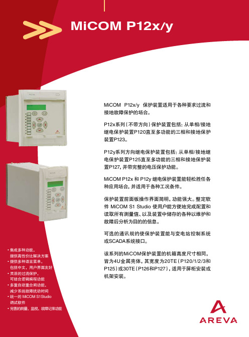
MiCOMP12x/y 保护装置适用于各种要求过流和接地故障保护的场合。
P12x系列(不带方向)保护装置包括:从单相/接地继电保护装置P120直至多功能的三相和接地保护装置P123。
P12y系列方向继电保护装置包括:从单相/接地继电保护装置P125直至多功能的三相和接地保护装置P127,并带完整的电压保护功能。
MiCOM P12x 和 P12y 继电保护装置能轻松胜任各种应用场合,并适用于各种工况条件。
保护装置前面板操作界面简明,功能强大。
整定软件 MiCOM S1 Studio 使用户能方便地完成配置和读取所有测量值、以及装置中储存的各种以维护和故障后分析为目的的信息。
可选的通讯规约使保护装置能与变电站控制系统或SCADA系统接口。
该系列的MiCOM保护装置的机箱高度尺寸相同,皆为4U金属壳体,其宽度为20TE(P120/1/2/3和P125)或30TE(P126和P127),适用于屏柜安装或机架安装。
优点• 集成多种功能,提供高性价比解决方案• 提供多种语言菜单,• 灵活的过流保护,可结合逻辑编程功能• 多重自动重合闸功能,减少系统故障扰动时间•调试软件• 完善的测量、监视、故障记录功能光耦输入输入类型光隔离输入功率10mA每个输入输入识别时间<5ms逻辑输入电气特性订货代号辅助电源电压范围逻辑输入的工作电压范围*最小触发电压A24~60Vdc24~250Vdc; 24~240Vac15VdcF48~250Vdc; 48~240Vac (EA**)24~250Vdc; 24~240Vac15VdcT48~250Vdc; 48~240Vac 24~250Vdc; 24~240Vac15VdcH48~250Vdc; 48~240Vac 105~145Vdc105Vdc V48~250Vdc; 48~240Vac 100Vdc; -30%/+20%77VdcW48~250Vdc; 48~240Vac 220Vdc; -30%/+20%154Vdc(*) 光耦输入的工作电压允许偏差为DC±20%,AC-20%至10%(**) 光耦输入的辨认时间经EA认证,采用24点采样滤波(50Hz时为15ms)开出接点开出接点类型银镍干接点!。
MiCOM P12x定值清单及说明
菜单文本
缺省整定
CONFIGURATION 配置
E/Gnd CT primary 接地 CT 一次测
E/Gnd CT sec 接地 CT 二次测
1000 1
LED5/6/7/8
关联指示灯
I>
5/6/7/8
Group Select
定制组选择
1
菜单文本
缺省设置
PROTECTION G1/G2 [50/51]Phase OC
步长
1
9999
1
1或5
I>、tI>、 I>>、tI>>、I>>>、 tI>>>、Ie>、tIe>、 Ie>>、tIe>>
Ie>>>、tIe>>>、 Therm Trip、 Brkn.Cond、CB Fail、tI2>、
tI2>>、Input1、Input2、Input3、 Input4、Input5、Recloser Run、 Recloser Blocked、tAux1、tAux2
0.005 x Ien 0.005 x Ien
DMT 定时限或 IDMT 反时限
Short time inverse(ALSTOM)、Standard Inverse(IEC)、Very inverse(IEC)、 Extremely inverse(IEC)、Lone time inverse(ALSTOM)、Short time inverse (CO2)、Moderately inverse (ANSI)、Inverse(CO8)、Very
YES
闭锁 tIe>>>
MiCOM P12y技术说明书
方向/无方向过流保护装置 技术说明书
Dec 2004
上海阿海珐电力自动化有限公司 中国上海南汇康桥工业区康意路 499 号 1/B 楼 邮编 201315 电话:+86 (0) 21 5812 8822 传真:+86 (0) 21 5812 8833
上海阿海珐电力自动化有限公司 MiCOMP12y 系列
第 2 页/共 33Байду номын сангаас页 技术说明书
目
1. 2.
录
装置简介 ................................................................................................................... 4 技术参数 ................................................................................................................... 5 2.1 额定参数 ............................................................................................................ 5 2.1.1 电源 ........................................................................................................... 5 2.1.2 频率 ...................................................................
MiCOM P24x技术说明书(1)
MiCOM P12y使用说明书

16 16 16 17 17 18 18
19 19 20
上海阿海珐电力自动化有限公司 MiCOMP12y 系列
6.3 检验要求 6.3.1 外观及配置、接线检查 6.3.2 绝缘电阻检测 6.3.3 逆变电源检验 6.3.4 通电检验 6.3.5 定值整定 6.3.6 开关量输入回路的检查 6.3.7 模拟量输入精度检验 6.3.8 保护定值检验 6.3.9 装置的整组联动试验 6.3.10 断路器联动试验 6.3.11 带负荷试验 6.3.12 结束工作
L7
报警指示灯(L2:桔黄色 LED 指示
灯,标注为 Alarm): 灯亮表示 MiCOM P12y
保护装
L8
置已发出过报警信号。无论是门槛
值越限(瞬动信号),还是发出跳
闸命令(延时信号),装置都会报
警。该指示灯将持续闪烁直到有人
阅读报警信息(阅读键 read),之
后指示灯将保持点亮但不再闪烁,
当报警信息被清除(清除键 clear)
MiCOM P12y
方向/无方向过流保护装置 使用说明书
Mar 2005
上海 AREVA 电力自动化有限公司 中国上海南汇康桥工业区康意路 499 号 1/B 楼
邮编 201315 电话:+86 (0) 21 5812 8822 传真:+86 (0) 21 5812 8833
上海阿海珐电力自动化有限公司 MiCOMP12y 系列
上海阿海珐电力自动化有限公司 MiCOMP12y 系列
第 9 页/共 24 页 使用说明书
3.3 保护装置标识
在可翻开的上盖板的下面,贴有装置的标识纸,上面有保护装置型号、序
列号、灵敏接地电流范围、额定值和订货代码等信息。
MICOMP整定说明(精品)
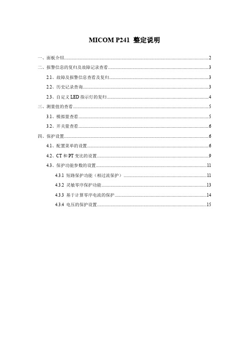
MICOM P241 整定说明一、面板介绍 (2)二、报警信息的复归及故障记录查看 (3)2.1、故障及报警信息查看及复归 (3)2.2、历史记录查询 (3)2.3、自定义LED指示灯的复归 (4)三、测量值的查看 (5)3.1、模拟量查看 (5)3.2、开关量查看 (6)四、保护设置 (6)4.1、配置菜单的设置 (6)4.2、CT和PT变比的设置 (9)4.3、保护功能参数的设置 (11)4.3.1 短路保护功能(相过流保护) (11)4.3.2 灵敏零序保护功能 (13)4.3.3 基于计算零序电流的保护 (14)4.3.4 电压的保护设置 (15)一、面板介绍L C D用户可编程L E D键盘测试端口前端通讯端口 电池下盖功能固定的L E D序列号和I, V 的额定值上盖1、 液晶显示(LCD ):可显示各项数据。
如整定值、测量值、报警信息等。
3、 用户自定义指示灯:(LED1、LED2‥‥‥LED7、LED8)可自定义功能。
可设为过流、速断、零序、低电压等。
如LED1定义为“过流”,当过流保护动作时,LED1点亮,为红色。
4、操作键盘:用户可通过、、、 四个键来进入各级彩单、移动光标、修改定值等。
键用来确认选项和个修改整定值。
5、阅读键:用来查看报警及故障信息。
6、复位键:用来复位故障及报警信息。
7、电池:当继电器失电时,用来保存事件纪录、故障记录、及时钟等。
8、前端通讯口:为RS232通讯接口,与当地PC 机通讯,可通过调试软件对保护装置进行定值整定、查看实时测量值、查看事件记录、故障记录、故障录波等。
9、型号、序列号:标有保护装置的具体型号、出厂序列号、工作电压范围等信息。
二、报警信息的复归及故障记录查看2.1、故障及报警信息查看及复归和键用于复位和读取故障及报警信息。
(键来查看报警信 息的内容,可重复按键来连续显示不同的报警内容。
告警指示灯不再闪烁时,可按键清除报警信息,按一下复位键清除一条告警信息,如有多条告警信息,则需多按几下。
MiCOMP12y技术说明书(1C)

3.1.1 三相过电流保护(P126、P127) ........................................19 3.1.2 方向接地保护(P125, P126 & P127).....................................20 3.1.3 热过负荷保护(P126、P127) ..........................................22 3.1.4 低电流保护(P126、P127) ............................................23 3.1.5 负序过电流保护(P126 & P127) .........................................23 3.1.6 断线检测(P126 & P127) ...............................................24 3.1.7 零序过电压保护(P125, P126 & P127)...................................24 3.1.8 低电压保护(P127) ...................................................24 3.1.9 过电压保护(P127) ...................................................25 3.1.10 自动重合闸 (P126 & P127) ............................................25 3.2 自动控制功能 ..............................................................27 3.2.1 负荷冷启动(P126 和 P127) .............................................27
MiCOM P12x使用说明书
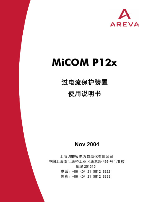
障,如典型的通信故障等。下侧 4 个为用户自定义指示灯。
4. 上、下盖板区域:顶部和底部盖板都可翻开。翻开上盖板可查看装置
型号、系列号以及额定值等;翻开下盖板可看到装置备用电池以及 9
针 RS232 串口 D 形母头。
3. 液晶显示
3.1 正常显示画面
正常情况下,MiCOM P12x 系列保护装置可连续显示所选的电流测量 值,可以是某个相电流或零序电流。
第一段负序过流门槛启动
第一段负序过流门槛延时信号启动
第二段负序过流门槛启动
第二段负序过流门槛延时信号启动
断路器故障指示,该信号从指定的逻辑输入处得到 (在 AUTOMAT.CTRL/Inputs(自动控制/输入)菜单 中设置)。 断路器动作(或跳闸)时间超过了 AUTOMAT.CTRL/CB Supervision(自动控制/断路器 监视)菜单中设置的时间。 断路器动作次数超出了 AUTOMAT.CTRL/CB Supervision(自动控制/断路器监视)菜单中设置的 值。 开断电流的测量值大于 AUTOMAT.CTRL/CB Supervision(自动控制/断路器监视)菜单中设置的 值。 断路器跳闸电路故障时间超出在 AUTOMAT.CTRL/CB Supervision(自动控制/断路器 监视)菜单中的设置的监视时间 t SUP。
目录
1.
装置介绍
2.
装置面板布置
3.
液晶显示
3.1 正常显示画面
3.2 故障报告显示
4.
菜单
4.1
主菜单结构
4.2 菜单操作
5.
密码
5.1 密码保护
5.2 密码的输入
5.3 密码的修改
6.
事件信息一览表
迪普森 P12-I 用户手册说明书

DP4603-01a-DIP12-IUser manualTABLE OF CONTENTSTABLE OF CONTENTS ___________________________________________________________________ 2 WARNINGS ____________________________________________________________________________ 3 EQUIPMENT ___________________________________________________________________________ 4 DESCRIPTION __________________________________________________________________________ 5 PRESET _______________________________________________________________________________ 6 HF DIRECTIVITY ________________________________________________________________________ 8 CROSSOVER FREQUENCY _______________________________________________________________ 8 ACCESSORIES _________________________________________________________________________ 9 ARRAY EQ ____________________________________________________________________________ 11 MAINTENANCE ________________________________________________________________________ 12 TECHNICAL SPECIFICATIONS ___________________________________________________________ 14 USER NOTES _________________________________________________________________________ 15Page 2 / 16P12-IWARNINGSP12-IPage 3 / 16PRECAUTIONSDo not open the speaker, do not try to disassemble it neither to modify it in any way. The system doesn’t include any user -repairable part.If the system seems to be malfunctioning or damaged, stop using it at once and have it repaired by a NEXO qualified technician. Do not expose the system directly to the sun or to the rain, do not immerse it into fluids, do not place objects filled with liquid on the system. If a liquid gets into the system, please have it inspected by a NEXO qualified technician. The connection should be performed by qualified technician, by ensuring that power is off.Operating temperature with temperate climate: 0°C to +40°C (+32°F to +104); -20°C à +60°C (-4°F to +140°F) for storage.SAFETY INFORMATIONSRead this manual before using the speaker. Keep this manual available for further reference. Observe all warnings and cautions.Please check the NEXO Web site to get the most up-to-date version of this manual.Ensure you are aware of the safety rules applying to rigging, stacking or installing on tripod or speaker stand. Failure to observe these rules may expose persons to potential wounds or even death. Only use the system with accessories specified by NEXO.Please always consult a NEXO-accredited technician if the installation needs architectural works and observe following precautions: Mounting Precautions :- Please select screws and mounting location supporting 4 times the system weight.- Do not expose the system to excessive dust, vibrations, to extreme cold or hot temperatures, to reduce the risk of damaging components.- Do not place the system in an unstable position: it could fall accidentally.-If the system is used on a tripod, please ensure the tripod’s specifi cations are adapted and that its height does not exceed 1.40m/55”. Do not move the tripod with the system in position .Connection and Powering Precautions:- Unplug connected cables before moving the system. - Power off the system before connecting the system.- When switching on the installation, the amplifier must be powered last; when switching the installation off, shut off theamplifier first.- If you work by cold temperatures, progressively raise the level to nominal value during the first minutes of use, to allow thesystem components to stabilize.Please check regularly the system condition.HIGH SOUND PRESSURE LEVELSExposure to very high sound pressure levels may cause permanent hearing losses. Degrees of hearing losses may be different from one person to another, but almost everybody will be affected if exposed to high sound pressure levels during a long period of time. The OSHA (Occupational Safety and Health Administration) American Agency specified the following maximal exposures:WASTE OF ELECTRIC OR ELECTRONIC EQUIPMENTThis symbol on the product or its packaging indicates that this product must not be treated as household waste. Instead, it is your responsibility to hand it over to a designated collection point for the recycling of waste electrical and electronic equipment. By ensuring your waste equipment is recycled, you will help preventpotential negative consequences for the environment and human health, which could appear if this product was not recycled. Recycling helps spare natural resources. For more information about the recycling of this product, please contact your local city office, your household waste disposal service or your reseller.EQUIPMENT3 locations for hanging, 1 on the back and on both sides. WARNING: The depth of the M10 thread is 13mm (0.5 inch).Assembly on distance rod or speaker standPage 4 / 16P12-IDESCRIPTION→The P12-I is a compact full-range coaxial speaker→P12 HF Dispersion:•60° - 60° with standard horn•90° – 40° with PNT-P12FLG9040•PS with PNT-P12FLGPS (Asymmetrical Dispersion)→P12 can be used alone or with L15 subwoofer→The speaker is equipped with a cable gland (clamping range, ø 5 to 12 mm), supplied with a fixed cable (HO7ZZ-F), 2 x1.5mm2 section, length 4m, outside diameter 8mm ±1mm.→(+) Red / (-) Black→Amplification•The P12 speakers must be used with a NEXO processor to handle EQ, phase alignment, crossover and excursion/thermal protection for the system loudspeaker. There are two NEXO processor series supporting the P12speakers: NXAMP (4 channels) amplified processors and DTD processors (stereo + sub). DTD processors ensureoptimal performances when used with DTDAMP power amplifiers.•The following table shows the number of P12 speakers and L15 subwoofers usable with each solution.P12-I Page 5 / 16PRESETFor the P12, the following setups are available:→MAIN is the recommended setup for most FOH application, similar to previous firmware setup.→MONITOR is recommended for monitor applications. Warning: this setup is a low latency setup and therefore its phase is not compatible with other NEXO cabinets, including subs.•P12 MON PA 6060, with high-pass at 60, 85 or 120 Hz.•P12 MON PA 9040, with high-pass at 60, 85 or 120 Hz.•P12 MON PA PSguide, with high-pass at 60, 85 or 120 Hz•P12 MAIN PA 6060, with high-pass at 60, 85 or 120 Hz.•P12 MAIN PA 9040, with high-pass at 60, 85 or 120 Hz.•P12 MAIN PA PSguide, with high-pass at 60, 85 or 120 Hz.Page 6 / 16P12-IPRESETP12-IPage 7 / 16HF DIRECTIVITY→The P12 speaker can be used in horizontal or vertical position.→The standard horn is a 60° - 60° dispersion. It’s easy to change the disp ersion by adding a specific flange. Different mounting possibilities and flange rotation allow to deal with every request.When replacing the grille, ensure it is well positioned in the top blade before fasten the hooks with the screws.CROSSOVER FREQUENCY→60 Hz: Full range application.→85 Hz: Use as « front fill » on stage, complementing a main system. Use with a NEXO subwoofer, e.g. L15.→120 Hz: Long throw application.Page 8 / 16P12-IACCESSORIESPNT-BUMPPNT-HBRK12PNT-PLADAPTPNT-VBRK12P12-I Page 9 / 16ACCESSORIESPNT-WMADAPTPNI-CLADAPTPNI-P12TOL15 / PNI-P12TO2L15PNI-WM330Page 10 / 16P12-IARRAY EQ PNT-P12FLGPSPNT-P12FLG9040ARRAY EQThe ArrayEQ allows to adjust the system frequency response in its lower range(see curves below, with different ArrayEq values):MAINTENANCE Driver accessMAINTENANCE Spare partsTECHNICAL SPECIFICATIONSP12-I WITH NEXO ELECTRONICSSPECIFICATIONSUSER NOTESNEXO S.A. Parc d’activité de la Dame JeanneF-60128 PLAILLYTel: +33 3 44 99 00 70 Fax: +33 3 44 99 00 30 E-mail:************。
维特迈克电子混合饮料机说明书

Use and Care Manual Read and save these instructionsVita-Mix® Corporation8615 Usher RoadCleveland, OH 44138-2103 U.S.A.1.800.848.2649 / 1.440.235.4840 * Product image may differ slightly from actual containerContents (2)Important Safeguards (3)Parts and Features (6)About the Blades (8)Tamper (9)Operating Instructions (11)Care and Cleaning (12)Warranty (13)Notes (15)23READ ALL INSTRUCTIONS, SAFEGUARDS, AND WARNINGS BEFORE OPERATING BLENDER.1. Read all instructions.2. Not intended for use by or near children or persons with reduced physical,sensory, or mental capabilities or lack of experience and knowledge. Close supervision is necessary when any appliance is used by or near children or incapacitated persons.3. To protect against the risk of electrical shock, do not put the blender base inwater or other liquid.4. Unplug from outlet when not in use, before putting on or taking off parts,and before cleaning.5. Avoid contacting moving parts.6. Do not operate any appliance with a damaged cord or plug or after theappliance malfunctions, or is dropped or damaged in any manner. Call Vitamix Customer Service at 1.800.848.2649 or 1.440.235.4840 or email ***************************************,repair,replacement,orelectrical or mechanical adjustment. If purchased outside the U.S.A. or Canada, contact your local Vitamix dealer.7. Alteration or modification of any part of the blender base or container,including the use of any part or parts that are not genuine authorizedVitamix parts, may cause fire, electric shock, or injury.8. The use of attachments not expressly authorized or sold by Vitamix for usewith this blender, including canning jars, may cause fire, electric shock, or injury.9. Do not use outdoors.10. Do not let cord hang over edge of table or counter.11. Do not let cord contact hot surface, including the stove.12. Keep hands and utensils out of container while blending to reduce the riskof severe injury to persons or damage to the blender. A rubber scraper or spatula may be used, but only when the Vitamix blender is not running.13. The tamper provided must be used only when the main part of the lid is in place.WARNING : To avoid the risk of serious injury when usingyour new Vitamix® container with your Vitamix blender, basic safetyprecautions should be followed, including the following.14. Blades are sharp. Handle or remove blade and blade assembly from thecontainer with extreme care to avoid injury. To reduce the risk of injury,never place a blade assembly on the motor base unless assembled to theVitamix container.15. Do not leave foreign objects, such as spoons, forks, knives or the lid plug,in the container as this will damage the blades and other components when starting the machine and may cause injury.16. Never attempt to operate with damaged blades.17. Always operate blender with lid and lid plug firmly in place. The lid plugshould be removed only when adding ingredients and when usingthe tamper.18. When blending hot liquids or ingredients, use caution; spray or escapingsteam may cause scalding and burns. Do not fill container to the maximumcapacity. Always begin processing on the lowest speed setting, variablespeed 1. Keep hands and other exposed skin away from the lid opening toprevent possible burns.19. When making nut butters or oil-based foods, do not process for more thanone minute after the mixture starts to circulate in the container. Processingfor longer periods can cause dangerous overheating.SAVE THESE INSTRUCTIONSIMPORTANT INSTRUCTIONS FOR SAFE USEThis product is intended for HOUSEHOLD USE ONLY and is not intended to be used for commercial purposes.Do not leave your Vitamix blender unattended when operating.Any repair, servicing, or the replacement of parts must be performed by Vitamix or an authorized service representative.4NOTICE:THE FAILURE TO FOLLOW ANY OF THE IMPORTANT SAFEGUARDS AND THE IMPORTANT INSTRUCTIONS FOR SAFE USE IS A MISUSE OF YOUR NEW VITAMIX CONTAINER WITH YOUR VITAMIX BLENDER THAT CAN VOIDALL WARRANTIES AND CREATE THE RISK OF SERIOUS INJURY.562-Part Lid: Your new container has a lid that is easy to put on and take off, and easy to clean. Always use the lid and the lid plug when the machine is in operation.CAUTION : Lids and tampers are not interchangeable between different container styles, types, and sizes.Snap the lid onto the container and leave in place for a few minutes. Once the lid has been left on the container, it will be much easier to lock or remove.Container: Ounces, cups, and milliliters are clearly marked.Tamper: While the machine is running, and only through the lid plug opening, use the tamper to press ingredients into the blades.Lid Plug: Insert through the lid and secure by turning clockwise. Remove the lidplug to use the tamper or add ingredients.* Product image may differ slightly from actual containerTo Lock the Lid in Place:1. Position lid on container with lid flaps midway between the spout andthe handle.2. Push the lid onto the container until it locks in place.3. The lid must always be secured when processing, especially hot liquids thatmay scald.To Remove the Lid: Lift up on one lid flap while holding the container securely.To Remove the Lid Plug: Rotate the lid plug counterclockwise from the “locked”to “unlocked” position and lift out.78Wet Blade Container: Designed for processing liquids,including juice, frozen mixtures, sauces, soups, purees,batters, and for wet chopping. The wet blades can alsogrind grain and knead dough, but they are not quite asefficient as the dry blades in this application. If used forgrinding, your container will mar and become cloudy; seeinstructions for dry container use.Dry Blade Container: These blades are clearly marked “D”and are designed specifically for grinding dry materials suchas grains, cereal, and coffee, and are also used for kneadingbread dough. The dry blades can NOT process liquidsefficiently. If you grind herbs on a regular basis, you maywish to purchase a separate dry blade container and replaceblades as needed.W DThe Vitamix machine comes standard with the wet blade container. The blade is identified by a “W” for wet. This blade is used for most of your recipes. Additional containers with wet or dry blades may be purchased separately.How to Determine the Tamper that Can Be Used with Your ContainerEach type of tamper is designed to be used safely and effectively with a particular container. If a tamper came with your container, it is the correct tamper for the container. If a tamper did not come with your container, or you want to determine if a tamper that you already have can be used with your new container, please compare your container with the containers and matching tampers to the illustration below.Before using the tamper during the blending process, verify that it is thecorrect tamper. For operating instructions, refer to the owner’s manual that was provided with your Vitamix blender.• 64 oz. Short Containers use Tamper P/N 016041 that is approximately 9-¾ inches long.• 64 oz. Tall Containers use Tamper P/N 000760 that is approximately 12-½ inches long.• 32 oz. and 48 oz. Containers use Tamper P/N 015033 that is approximately11 inches long.9To verify that you are using the correct tamper, place the lid on an emptycontainer, remove the lid plug and insert the tamper. If it is the correct tamper, it should easily fit into the opening but will not come in contact with the blades no matter how you move the tamper inside the container. IF THE TAMPERTOUCHES THE BLADES AT ANY ANGLE - DO NOT USE THE TAMPER WITH YOUR CONTAINER.If you do not have the correct tamper for your container, call Vitamix Customer ******************************************************************** order a new tamper. If purchased outside the United States or Canada, contact your local Vitamix Dealer.10Wet Blade ContainerDesigned for processing liquids including juice, frozen mixtures, sauces, soups, purees, batters, and for wet chopping.For operating instructions, refer to the owner’s manual that was provided with your Vitamix blender.Dry Blade ContainerIf purchased, your dry blade container should only be used for hard, dry materials such as grain, and for kneading dough.For operating instructions, refer to the owner’s manual that was provided with your Vitamix blender.11ContainerTo prepare your new container for initial use, follow the steps below.1. Fill the container half full with warm water and add a couple drops of liquiddish washing detergent to the container.2. Snap or push the complete 2-part lid into locked position.3. Refer to owner’s manual supplied with the machine. Set the machine to thelowest speed setting. Turn machine on and increase speed to the highestspeed setting.4. Run the machine on High speed for 30 to 60 seconds.5. Turn off the machine, and rinse and drain the container.Note: Some thick mixtures, such as breads and batters, may need additionalwashing by hand. When storing the lid on the container, either remove the lid plug or thoroughly dry both the lid and container to avoid trapping moisture.Lid, Lid Plug and Tamper:Separate the lid and lid plug. Wash the parts in warm soapy water. Rinse clean under running water, and dry. Reassemble before use.IMPORTANT: To ensure continued and effective performance, do not put the container, lid, lid plug or tamper in the dishwasher.123-YEAR FULL WARRANTY ON SEPARATELY SOLD CONTAINER AND CONTAINER COMPONENTS1.WHAT IS COVERED.Vita-Mix Corporation (“Vitamix”) warrants that a container (the “Container”),lid, blade assembly and/or retainer nut (the (“Container Component”) thatis purchased separately from a blender motor-base will be free from defectsin material or workmanship and will withstand wear and tear from ordinaryhousehold use for 3 years from the date of purchase. Vitamix will, within 30days of receipt of the returned product, repair the failed Container or Container Component free of charge. If, in Vitamix’s sole discretion, the failed Containeror Container Component cannot be repaired, Vitamix will elect to either (A)replace the Container or Container Component free of charge or (B) refund the full purchase price to the owner, unless Vitamix receives prior written notice ofthe owner’s preference.2.WHAT IS NOT COVERED.This Warranty applies only to owners for ordinary household use. ThisWarranty does not cover cosmetic changes that do not affect performance,such as discoloration or the effects of the use of abrasives or cleaners or foodbuild up. This Warranty is only valid if the Container or container in which theContainer Component is installed is used in accordance with the instructions,warnings and safeguards contained in the owner’s manual.Vitamix will not be responsible for the cost of any unauthorizedwarranty repairs.REPAIR, REPLACEMENT OR REFUND OF THE PURCHASE PRICE ARE THEEXCLUSIVE REMEDIES OF PURCHASER AND THE SOLE LIABILITY OFVITAMIX UNDER THIS WARRANTY. NO EMPLOYEE OR REPRESENTATIVE OF VITAMIX IS AUTHORIZED TO MAKE ANY ADDITIONAL WARRANTY OR ANYMODIFICATION TO THIS WARRANTY WHICH MAY BE BINDING UPONVITAMIX. ACCORDINGLY, PURCHASER SHOULD NOT RELY UPON ANYADDITIONAL STATEMENTS MADE BY ANY EMPLOYEE OR REPRESENTATIVEOF VITAMIX. IN NO EVENT, WHETHER BASED ON CONTRACT, INDEMNITY,WARRANTY, TORT (INCLUDING NEGLIGENCE), STRICT LIABILITY OROTHERWISE, SHALL VITAMIX BE LIABLE FOR ANY SPECIAL, INDIRECT,INCIDENTAL OR CONSEQUENTIAL DAMAGES, INCLUDING, WITHOUTLIMITATION, LOSS OF PROFIT OR REVENUE.Some states do not allow limits on warranties. In such states, the abovelimitations may not apply to you. Outside the U.S.A. and Canada, otherwarranties may apply.133.WHAT VOIDS THIS WARRANTY.Abuse, misuse, negligent use, alteration of the Container or ContainerComponent or motor base, exposure to abnormal or extreme conditions, orfailure to follow the operating instructions, will void this Warranty.The Warranty is also void if repairs to the machine, Container, ContainerComponent or any portion of the blade assembly are performed by someoneother than Vitamix or an authorized Vitamix Service Provider or if any partsubject to this Warranty is used in combination with a motor-base or containerthat is not expressly authorized by Vitamix.4.HOW TO OBTAIN RETURN AUTHORIZATION UNDER THIS WARRANTY.In the event the Container or Container Component needs service or repair,please call Vitamix Customer Service at 1.800.848.2649. You will be asked toprovide a date of purchase and proof of purchase for any product that has notbeen registered with Vitamix. For product subject to this Warranty you will beprovided with a return authorization number, up-to-date shipping instructionsand a pre-paid return pick up label. Vitamix will pay standard shipping costson the return of a Container or Container Component for warranty service andrepair and for return shipment of the product to you after the warranty repair orreplacement. Purchaser is responsible for the costs of special shipping requests.Within the U.S.A. and Canada, this Warranty is honored directly through theVita-Mix® Corporation.United States CanadaVita-Mix® Corporation Vita-Mix® Corporation8615 Usher Road 200-1701 Shepherd Street EastCleveland, Ohio 44138-2199 Windsor, Ontario N8Y 4Y51.800.848.2649 1.800.848.2649**************************************You will be deemed to have accepted the returned product “as is” upon deliveryunless you notify Vitamix of any problem, including shipment damage, within48 hours of delivery.SPECIAL INTERNATIONAL INSTRUCTIONSIf a machine was purchased within the U.S.A. or Canada,but is currently outside the U.S.A. or Canada,all shipping and resulting taxes and duties are at the owner’s expense.Call+******************************************************.14___________________________________________________________________________________________________________________________________________________________________________________________________________________________________________________________________________________________________________________________________________________________________________________________________________________________________________________________________________________________________________________________________________________________________________________________________________________________________________________________________________________________________________________________________________________________________________________________________________________________________________________________________________________________________________________________________________________________________________________________________________________________________________________________________________________________________________________________________________________________________________________________________________________________________________________________________________________________________________________________________________________________________________15T o see the complete line of Vitamix® products,visit .Vita-Mix® Corporation8615 Usher RoadCleveland, OH 44138-2103 U.S.A.1.800.848.2649 / 1.440.235.4840©2013 Vita-Mix®Corporation. No part of this publication may be reproduced or transmitted in any form orby any means or stored in a database or retrieval system without the written permission of the Vita-Mix® Corporation. Printed in the U.S.A.103777 3/13。
Vacmaster VOC1210PF 12 Gallon Wet Dry Vacuum 操作手册说
Distributed ByCleva North America, Inc.601 Regent Park CourtReplacement Filters &Accessories available at:FOR YOUR SAFETY Read and understand this manual before use.Keep this manual for future reference.12 Gallon Model No.VOC1210PFOperator’s Manual Wet/Dry VacuumWarranty………………………………………………………………………………….........…………. Safety Instructions & Warnings………………………………………………….........……………...... Double Insulation Instructions....………………………………………………........….………………Extension Cords………………………………………………………………........……….…………. Unpacking & Checking Carton Contents………….…………………….........……….………....……General Assembly Instructions……………………………………………….........…………………... Dry Vacuum Operation…………………………………………………….......….………….…………. Liquid Vacuum Operation…………………………………………………........………….……………Blower Operation……………………………………………………….........…………….…………... Maintenance……………………………………………………………….........……………………….. Installing & Cleaning Cartridge Filter……………………………...……........….……..….………….. Installing & Cleaning Foam Wet Filter………………………...……........………….…...….…….. Troubleshooting………………………………………………………….........…………………………Exploded View………………………………………………………........…..……….......................... Parts List.......................................................................................................................................2 3 4 4 5 6 7 8 9 9 10 10 11 12 13SECTION PAGEThank you for purchasing this Vacmaster® wet/dry vacuum cleaner. Feel confidentthat with Vacmaster® you are obtaining a high quality product engineered for optimal performance. This vacuum is capable of picking up liquids and dry materials.FOR YOUR SAFETY: CAREFULLY READ AND UNDERSTAND ALL INSTRUCTIONS.We take pride in producing a high quality, durable product. This Vacmaster® product carries a limited two (2) year warranty against defects in workmanship and materials from date of purchase under normal household use. If product is to be used for commercial, industrial, or rental use, a 90 day limited warranty will apply. Please keep your receipt as proof of purchase. This warranty gives you specific legal rights, and you may have other rights, which vary from state to state. For product service call Customer Service at 1-866-384-8432.Not Covered by Warranty:• Any part that has become inoperative due to misuse, negligence, direct/indirect abuse, accidents, improper maintenance, repairs, or alterations;• Consumables such as filters and accessories;• Normal wear and tear of parts and attachments, such as hose, nozzles, or casters;• Normal deterioration of the exterior finish due to use or exposure;• Any product where serial number/data label is tampered with or removed;• Any product purchased from an unauthorized retailer.IMPORTANT SAFETY INSTRUCTIONS SAVE THIS MANUAL WARNING:FOR FUTURE REFERENCE.TO REDUCE THE RISK OF FIRE, ELECTRIC SHOCK, OR INJURY:READ AND UNDERSTAND ALL INSTRUCTIONS BEFORE USING THIS VACUUM. Read and understand this operator's manual and all labels on the Wet/Dry Vacuum cleaner before operating. Safety is a combination of common sense, staying alert, and knowing how your vacuum works. Use this Wet/Dry Vac only as described in this manual. To reduce the risk of personal injury or damage to your Wet/Dry Vac, use only Vacmaster ® recommended accessories.When using an electrical appliance, basic precautions should always be followed including the following:• Do not run vac unattended.• Do not vacuum, or use this Wet/Dry Vac near flammable liquids, gases, or explosive vapors like gasoline or other fuels, lighter fluids, cleaners, oil-based paints, natural gas, hydrogen, or explosive dusts like coal dust, magnesium dust, grain dust, or gun powder. Sparks inside the motor can ignite flammable vapors or dust.• Do not vacuum anything that is burning or smoking, such as cigarettes, matches, or hot ashes.• Keep cord away from heated surfaces.• Do not expose to rain. Store indoors.• Do not unplug by pulling on cord. To unplug, grasp the plug, not the cord.• Do not use with damaged cord, plug, or other parts.• If appliance is not working as it should, has been dropped, damaged, left outdoors, or dropped into water, return it to a service center.• Do not pull or carry by cord, use cord as handle, close a door on cord, or pull cord around sharp edges or corners.• Do not run Wet/Dry Vac over cord.• Do not handle plug or the Wet/Dry Vac with wet hands.• To reduce the risk of health hazards from vapors or dusts, do not vacuum toxic materials.• Do not use or store near hazardous materials.• Do not use this Wet/Dry Vac with a torn filter or without the filter installed except when vacuuming liquids as described in the operation section of this manual.• Do not allow to be used as a toy. Close attention is necessary when used by or near children.• To reduce the risk of injury from accidental starting, unplug power cord before changing or cleaning filter.• Do not leave Wet/Dry Vac unattended when plugged in. Unplug from outlet when not in use and before servicing. • Turn off Wet/Dry Vac before unplugging.• Do not put any object into ventilation openings. Do not vacuum with any ventilation openings blocked; keep free of dust, lint, hair, or anything that may reduce air flow.• Keep hair, loose clothing, fingers, and all parts of body away from openings and moving parts.• To reduce the risk of falls, use extra care when cleaning on stairs.• Unplug before connecting hose.• Use only as described in this manual. Use only manufacturer’s recommended attachments.• This appliance is provided with double insulation. Use only identical replacement parts. See “DOUBLE INSULATION INSTRUCTIONS”.When using as blower:• Direct air discharge only at work area. • Do not use Wet/Dry Vac as a sprayer.• Do not direct air at bystanders.• Keep children away when blowing.• Use safety goggles.Household TypeEXTENSION CORDSThis Wet/Dry Vac is double-insulated, eliminating the need for a separate grounding system. Use only identical replacements parts. Read the instructions for Servicing Double-Insulated Wet/Dry Vacs before servicing. Use this Wet/Dry Vac as described in this manual. Observe the following warnings that appear on the motor housing of your Wet/Dry Vac.When using an extension cord with your Wet/Dry Vac refer to the following table to determine the required A.W.G. wire size. Before using the cleaner make sure the power cord and extension cord are in good working condition. Make repairs or replacements before using the vacuum cleaner. Only use extension cords that are rated for outdoor use.• To reduce the risk of electric shock-unplug before cleaning or servicing.• DO NOT use without filters in place.CAUTION: TO REDUCE THE RISK OF INJURY FROM MOVING PARTS, UNPLUG BEFORE SERVICING.CAUTION:Do not vacuum drywall dust or fireplace soot or ash with standard Wet/Dry filter. This is a very fine dust which will not be captured by the filter and may cause damage to motor. When vacuuming fine dust use a fine dust filter (sold separately).DOUBLE INSULATED - GROUNDING NOT REQUIRED - WHEN SERVICING USEONLY IDENTICAL REPLACEMENT PARTS.TO REDUCE THE RISK OF ELECTRIC SHOCK, DO NOT EXPOSE TO RAIN.STORE INDOORS.WARNING:Length of Extension Cord A.W.G. Wire Size Not recommended25 Feet 7.5 Meters50 Feet 15.25 Meters 100 Feet 30.5 Meters 150 Feet 45.7 Meters 110V-120V Amps 0-67-1011-1213-161818161416161612161414141212FC DAGEKH IJ LBRemove all contents from the box. Removethe power head and take out any contentsinside the collection tank. Check each itemagainst the carton contents list.Carton Contents List:Key Description ..…………....……….….... Qty.NOTE: The hose and accessories for thisvacuum are 2.5” diameter.111421111111ABCDEFGHIJKLVac Assembly…………………….……..Hose……………………………………...Utility Nozzle………………………..…...Caster Foot Assembly...........................Extension Wands……………………….Crevice tool...……………………………Floor Nozzle.................………..……….Cartridge Filter………………..…………Filter Retainer…………………………...Foam Wet Filter.………….…….…....4 Screws (Bag)…………….……………Operator’s Manual…..………………….HandlePower HeadVacuum PortAccessory StorageCollection TankDrain CasterCaster FootA Philips head screw driver is required.1. Verify that the power cord is disconnected from the outlet. (fig. 1)2. Undo the latches. (fig. 2)3. Lift the power head off the collection tank. (fig. 3)4. Remove the contents from inside the collection tank; make sure you have all contents as listedon page 5. (fig. 4)5. Turn the collection tank upside down and insert the four caster feet into the slots on thecollection tank and tighten with supplied screws. Verify that the casters are mounted correctly.Do not over-tighten screws. (fig. 5)6. Your vacuum comes ready for dry vacuum cleaning. For installation instructions, see page 10.(fig. 6 & 7)7. For wet vacuum cleaning, install the supplied foam wet filter. (fig. 8) See page 11 for filterinstallation.8. Place the power head back on the collection tank, aligning the top section with the latches, andsnap into place. (fig. 9)9. Insert the locking end of the hose into the port of the collection tank and lock into place. (fig.10)10. Choose the desired accessories and push onto the suction tube. (fig. 11)POLARIZED PLUGTo reduce the risk of electrical shock, this appliance has a polarized plug (one blade wider than the other). This plug will fit in a polarized outlet only one way. If the plug does not fit fully in the outlet, reverse the plug. If it still does not fit, contact a qualified electrician to install the proper outlet.Do not change the plug in any way. Double insulation eliminates the need for the three wire grounded power cord and grounded power supply system.WARNING: BE SURE TO READ, UNDERSTAND, AND APPLY, INFORMATION, ENTITLED ‘SAFETY INSTRUCTIONS & WARNINGS’. DO NOT VACUUM IN AREAS WITH FLAMMABLE GASES, VAPORS, OR EXPLOSIVE DUSTS IN THE AIR. FLAMMABLE GASES OR VAPORS INCLUDE BUT ARE NOT LIMITED TO: LIGHTER FLUID, SOLVENT TYPE CLEANERS, OIL-BASED PAINTS, GASOLINE, ALCOHOL, OR AEROSOL SPRAYS. EXPLOSIVE DUSTS INCLUDE BUT ARE NOT LIMITED TO: COAL, MAGNESIUM, GRAIN, OR GUN POWDER. TO REDUCE THE RISK OF HEALTH HAZARDS FROM VAPORS OR DUST, DO NOTVACUUM TOXIC MATERIALS.1. Verify that the power cord is disconnected from the outlet. (fig. 1)2. In order to prepare your vacuum for dry vacuuming, verify that the cartridge filter is securelymounted. Make sure the filter is pushed in until it stops against the power head. (fig. 2) Your Wet/Dry Vac comes with the cartridge filter pre-installed. For installation instructions, see page 10.3. Place filter retainer on top of cartridge filter and tighten down by turning the retainer handleclockwise. (fig. 3)4. Optional: For improved dust filtering, fit collection bag flange onto inlet port, taking care not todamage the bag. Dust bag sold separately. (fig. 4)5. Place the power head back on the collection tank, aligning the top section with the latches, andsnap into place. (fig. 5)OPERATING INSTRUCTIONS: DRY VACUUMING6. Insert the locking end of the hose into the vacuum port on the power head and lock into place.Push the required attachment onto the free end of the hose or extension. (fig. 6)7. Plug the power cord into the outlet. (fig. 7)8. Turn the motor on by flipping the switch to the ‘I’ ON position. (fig. 8)9. Once you have completed vacuuming, flip the switch to the ‘O’ OFF position and unplug thepower cord from the outlet.O = OFF I = ONDO NOT USE THE CARTRIDGE FILTER FOR LIQUID VACUUMING.DRY VACUUMINGWARNING: BE SURE TO READ, UNDERSTAND, AND APPLY, INFORMATION, ENTITLED ‘SAFETY INSTRUCTIONS & WARNINGS’. DO NOT VACUUM IN AREAS WITH FLAMMABLE GASES, VAPORS, OR EXPLOSIVE DUSTS IN THE AIR. FLAMMABLE GASES OR VAPORS INCLUDE BUT ARE NOT LIMITED TO: LIGHTER FLUID, SOLVENT TYPE CLEANERS, OIL-BASED PAINTS, GASOLINE, ALCOHOL, OR AEROSOL SPRAYS. EXPLOSIVE DUSTS INCLUDE BUT ARE NOT LIMITED TO: COAL, MAGNESIUM, GRAIN, OR GUN POWDER. TO REDUCE THE RISK OF HEALTH HAZARDS FROM VAPORS OR DUST, DO NOTVACUUM TOXIC MATERIALS.WARNING: DO NOT PLUG POWER CORD INTO POWER OUTLET, MAKE SURE PLUG IS DISCONNECTED BEFORE ASSEMBLING THE WET/DRY VAC.LIQUID VACUUMING1. Verify that the power cord is disconnected from the outlet. (fig. 1) Verify that the collection tank is clean and free of dust and dirt.2. Remove cartridge filter, then carefully install the foam wet filter over the filter cage and place the power head back on the collection tank. (fig. 2) For filter installation instructions, see page 11.DO NOT USE THE CARTRIDGE FILTER FOR LIQUID VACUUMING.OPERATING INSTRUCTIONS: WET VACUUMING 3. Fit the desired nozzle to the vacuum hose. (fig. 3)4. Verify that the switch is in the ‘O’ OFF position before plugging the power cord into the outlet. (fig. 4)5. Turn the motor on by flipping the switch to the ‘I’ ON position. (fig. 5)6. Once you have completed vacuuming, flip the switch to the 'O' OFF position and unplug the power cord from the outlet.7. After use, empty the collection tank by unscrewing the drain cap. Drain liquids into a suitable receptacle or drain. Remember to refit the drain cap to the collection tank. (fig. 6)IMPORTANT! When vacuuming large quantities of liquids, do not immerse the nozzle completely in the liquid; leave a gap at the tip of the nozzle opening to allow air inflow. The machine is fitted with a float valve that stops the suction action when the collection tank reaches its maximum capacity. You will notice an increase in motor speed. When this happens, turn off the machine, disconnect from power supply, and drain the liquid into a suitable receptacle or drain. To continue vacuuming, refit the collection tank with the drain cap. After wet vacuuming, turn the machine off and remove plug from power supply. Empty the collection tank, clean and dry the inside and outside before storage. REMEMBER! The foam wet filter must be removed after wet vacuuming,and a cartridge filter must be installed before dry vacuuming again.WARNING: ALWAYS WEAR SAFETY GOGGLES COMPLYING WITH ANSI Z87.1 (OR IN CANADA, CSAZ94.3) BEFORE USING BLOWER.WARNING: KEEP BYSTANDERS CLEAR FROM BLOWING DEBRIS.WARNING: WEAR A DUST MASK IF BLOWING CREATES DUST THAT MIGHT BEINHALED.1. Verify that the power cord is disconnected from the outlet. (fig. 1)2. Make sure the collection tank is empty before using as a blower.3. Remove hose from the vacuum port.4. Insert the locking end of the hose into the blower port on the back side of the power head and lock into position. (fig. 2)5. Fit the desired extension wand and or nozzle to the vacuum hose. (fig. 3)6. Ensure the power switch is turned off and plug in the power supply. (fig. 4)7. Before turning on the vac, firmly hold loose end of the hose. Turn the motor on by flipping the switch to the ‘I’ ON position. (fig. 5)2. Disconnect the hose from the vacuum. (fig. 2)3. Undo the latches and remove the power head from the collection tank. (fig. 3)4. Clear all dirt or debris from the collection tank and hose. (fig. 4)5. Clean the foam wet filter by washing it with water and mild soap. (fig. 5)6. Check the hose, attachments, and power cord to verify that they have not been damaged.IMPORTANT! Clean or change the cartridge filter regularly for best performance. ALWAYS USE CARTRIDGE FILTER FOR DRY VACUUMING. If the machine is used without the cartridge filter, the motor will burn out and the warranty will be voided. Always keep spare filters on hand. NOTICE! The filters included are made of high quality materials designed to stop small dust particles. The cartridge filter should be used for dry pick-up only. A dry cartridge filter is necessary to pick up dust. If the cartridge filter is wet, it will clog quickly and be very difficult to clean. Handle the filter carefully when removing it for cleaning and replacing it. Check the filters for tears or small holes, a small hole can let dust pass through and out of the filter. Do not use a filter with holes or tears; replace it immediately.Installing Cartridge Filter 1. Verify that the power cord is disconnected from the outlet. (fig. 1)2. Remove power head and place in upside down position.3. Install the cartridge filter over the filter cage with the flat end of the filter towards the power head. Carefully push filter in until it stops against the power head. (fig. 2 & 3)4. Place filter retainer on top of cartridge filter over the raised lip and tighten down by turning retainer clockwise; do not over-tighten. (fig. 4 & 5)Removing and Cleaning Cartridge Filter 1. Unlock and remove the filter retainer by turning retainer handle counter clockwise.2. Carefully hold and pull the cartridge filter up for removal. (fig. 6)3. Clean the cartridge filter by gently tapping or brushing dirt off. Cleaning should not be done indoors in living areas. For optimal performance a new filter is recommended.4. Install cleaned or new filter into place as instructed above in steps 2 and 3 of Installing Cartridge Filter.5. Wet filters should be removed and allowed to air dry for 24 hours before installing onto the filter cage.WARNING! ALWAYS DISCONNECT THE PLUG FROM THE POWER OUTLET BEFORE REMOVING THE POWER HEAD FROM THE COLLECTION TANK.Installing Foam Wet Filter1. Verify that the power cord is disconnected from the outlet. (fig.1)2. Remove power head and place in upside down position. Follow instructions to remove cartridgefilter.3. Carefully slide foam wet filter down over the filter cage making sure the cage is completelycovered. (fig. 2 & 3)4. Place the power head onto the collection tank.Cleaning Foam Wet Filter1. With the removed power head in an upside down position, carefully remove foam wet filter. (fig.4)2. Use a mild soap and water solution to wash foam wet filter and rinse with clean water. (fig. 5)3. Allow filter to air dry before installing and using again.WARNING! TO REDUCE THE RISK OF ELECTRIC SHOCK, UNPLUG BEFORE TROUBLESHOOTING.Symptom Possible Causes Corrective ActionVacuum will not operate1) No power supply.1) Check power supply – cord,breakers, fuses.2) Faulty power cord.2) Unplug and check the powercord. If damaged, have itrepaired by a professional.3) Collection tank full.3) Empty collection tank.Dust comes out from motor cover.1) The cartridge filter is missingor damaged.1) Attach or replace cartridgefilter.Reduced efficiency and motor/ speed vibration.1) There is a blockage in thenozzle, hose, or the collectiontank inlet. The cartridge filter isclogged by fine dust.1) Check nozzle, hose andcollection tank inlets forblockage. Take off the filterand clean it or install a newcartridge filter.Part Drawing Number Description Quantity 1551245001Handle Assembly 12Power Head Assembly 1 3551005103Float Cup1 4551005104Filter Cage 15Collection Tank 1 6551011106Vacuum Port Assembly1 7551002110Drain Cap Assembly 1 8551006109Caster Foot Assembly 49V2H7Hose1 10V2EW Extension Wands 2 11V2FBS Floor Nozzle1 12V2UN Utility Nozzle1 13V2CT Crevice Tool1 14VCFF Cartridge filter1 155********Filter Retainer1 16VFF51Foam Wet Filter1。
- 1、下载文档前请自行甄别文档内容的完整性,平台不提供额外的编辑、内容补充、找答案等附加服务。
- 2、"仅部分预览"的文档,不可在线预览部分如存在完整性等问题,可反馈申请退款(可完整预览的文档不适用该条件!)。
- 3、如文档侵犯您的权益,请联系客服反馈,我们会尽快为您处理(人工客服工作时间:9:00-18:30)。
在可翻开的下盖板的下面,有一个电池舱,可使用½AA 型电池。该电池可作
为后备电源,保存保护装置存储器中的事件记录,故障记录和故障录波(仅对
P126 和 P127)。盖板下还有一个 9 针的母 D 型前部通讯端口。它的作用是通过
RS232 串行数据连接(SK1 口),在本地实现 PC 机和保护装置的通讯(最长距离
且跳闸原因也被复位后,指示灯熄
灭。
警告指示灯(L3:桔黄色 LED 指示灯,标注为 Warning):
灯亮表示 MiCOM P12y 保护装置有内部警告。当检测到一个“非严重”的内部 警告时,该指示灯将持续闪烁。只有当导致内部警告的原因不存在了(修理模块,故 障消失等),指示灯才会熄灭。
辅助电源(L4:绿色 LED 指示灯,标注为 Aux. Supply):
灯亮表示 MiCOM P12y 保护装置工作正常,装置电源的辅助电源存在。
可自由编程的指示灯(L5 to L8:标签自由标注):
这些 LED 指示灯可以由用户以提供的门槛(瞬动和延时信号)信息为基础自由 编程。用户选择他想用指示灯看到的信号,通过菜单将它们分配到每一个 LED 指示 灯上(用逻辑 OR)。当相关信号启动时,对应的指示灯亮。当相应的报警被确认了 之后,指示灯熄灭。
第 3 页/共 24 页 使用说明书
21 21 21 21 21 22 22 23 23 23 24 24 24
上海阿海珐电力自动化有限公司 MiCOMP12y 系列
第 4 页/共 24 页 使用说明书
1. 装置介绍
MiCOM P125、P126、P127 系列保护装置是法国 AREVA 公司继 K 系列、 MODN 系列以及 MX3 系列产品获得成功后新研制的换代产品。所设计的 MiCOM P125、 P126、P127 保护装置具有保护、控制和监视等多重功能,适用于工业, 配电网络和变电站中,可作为变压器和发电机变压器保护方案的一部分以及为高压 和超高压输电系统提供后备保护等。
(带外壳接地连线)
上海阿海珐电力自动化有限公司 MiCOMP12y 系列
4. 液晶显示
第 11 页/共 24 页 使用说明书
4.1 正常显示画面
正常情况下,MiCOM P12y 系列保护装置可连续显示所选的电流测量值, 可以是某个相电流或零序电流。
IA 0.00A
4.2 故障报告显示
正常显示 画面
装置前面板上的各元件描述如下。P125,P126 和 P127 前面板的功能是
一样的。
液晶显示屏(LCD)
可显示 2 行,最多 16 个字母/数字
IA
的液晶显示屏(LCD)。
键盘:
一个带 7 个按钮的键盘,包 括:4 个方向导航键,1 个回车键, 1 个清除键和 1 个阅读键。利用键 盘,用户可十分方便对装置进行操 作。
为 15m)。
上海阿海珐电力自动化有限公司 MiCOMP12y 系列
3.5 P125 P126/P127 保护装置背面的描述
3.5.1 P125 的背面描述
外壳接地
第 10 页/共 24 页 使用说明书
模块端子排 背视图
(带外壳接地连线)
3.5.2 P126/P127 的背面描述
外壳接地
模块端子排 背视图
第 6 页/共 24 页 使用说明书
可提供的型号
AN SI代码
67N/ 50N/ 51N 67/ 50/ 51 50/ 51
32N/ Iecos (*)
37 46 49 27 59 59N 79 50BF
M iCO M P1 2 5 o
o
o
o
o 1 o
o o o o o
M i CO M P1 2 6 o
上海阿海珐电力自动化有限公司 MiCOMP12y 系列
第 9 页/共 24 页 使用说明书
3.3 保护装置标识
在可翻开的上盖板的下面,贴有装置的标识纸,上面有保护装置型号、序
列号、灵敏接地电流范围、额定值和订货代码等信息。
下面列出了每个信息代表的含义:
P127CAF11:CORTEC 代码(订货 代码)通过本代码,用户可以知道保 护装置的特性 No.:0000000:装置的序列号
I>
一段过流保护启
动
再按 键可对故障信息复归,LCD 显示恢复为默认的测量值。 报警信息可分为:
⇒ 电气系统报警信息 ⇒ 保护装置的硬件或软件的故障信息
上海阿海珐电力自动化有限公司 MiCOMP12y 系列
第 12 页/共 24 页 使用说明书
4.2.1 电气系统报警信息
任何一个超过整定值(瞬动或延时)的情况都会产生一条“电气报警信
上海阿海珐电力自动化有限公司 MiCOMP12y 系列
第 5 页/共 24 页 使用说明书
MiCOM P127
带功率元件,过/欠电压和自动重合闸的方向过流和方向 接地故障保护装置
上海阿海珐电力自动化有限公司 MiCOMP12y 系列
2. 主要功能
功能
方向/ 无方向接地故障保护 方向/无方向相过流 三相过流 瓦特制式保护(Pe或Iecos) 断线检测 欠电流 负序过流 热过负荷 欠电压 过电压 零序过电压 自动重合闸(4次) 断路器失灵 断路器监视和控制 闭锁逻辑 负荷冷启动 装置逻辑方案可选 启动接点 可编程与AND逻辑 整定值组 测量 故障记录 事件记录 故障录波 调试功能 诊断/ 自检 网络通讯 RS232通讯口 支持软件包(MiCOM S1)
次复位所有报警信息。
ALARM LED(报警指示灯)的状态直接由装置所存储的报警信息的状态决
定。如果还有一条或者几条信息没有阅读和复位,报警 LED 指示灯闪烁。如果
所有信息都阅读了,但是没有进行复位,则报警 LED 指示灯一直保持亮。当所
有报警信息都复位了,则报警 LED 指示灯熄灭。
4.2.2 保护装置硬件或软件报警信号
MiCOM 保护装置可采用直流或交流辅助电源供电。短时辅助电压陡降(小 于 50ms)都不会对装置功能产生任何影响。
装置的前面板上配备了液晶显示屏(LCD),能显示 2 x 16 个带背光的数字 和字符。通过液晶显示屏幕以及简单的键盘操作,用户可方便的读取装置信息、保 护整定以及实时测量值等。同时面板上 8 个 LED 指示灯可明显提示所发生的故障
Cde: 00000/000:装置订货参考信 息 当装置出现问题时,用户必须提供这 些信息以便维修。 Un = 57 – 130V:电压互感器输入的 范围。 Modbus:通讯规约,通过后部 RS485 通讯口实现。 0.002 Ien:灵敏接地故障电流(有 三个灵敏等级) Ua = 48-150Vdc:装置电源的电压 范围。在本例中,电源只能是直流 DC。
L7
报警指示灯(L2:桔黄色 LED 指示
灯,标注为 Alarm): 灯亮表示 MiCOM P12y
保护装
L8
置已发出过报警信号。无论是门槛
值越限(瞬动信号),还是发出跳
闸命令(延时信号),装置都会报
警。该指示灯将持续闪烁直到有人
阅读报警信息(阅读键 read),之
后指示灯将保持点亮但不再闪烁,
当报警信息被清除(清除键 clear)
任何软件和硬件错误都会在 MiCOM 保护装置显示屏上产生一条“硬件/软 件报警”信息。如果同时产生了几条报警信号,则按照它们产生的先后秩序被 储存起来,显示时按照与发生时间相反的顺序(即最近产生的先显示,最早发 生的最后显示),每条信息都被编上号,信息的总条数也显示在下面。
语。
跳闸指示灯(L1:红色 LED 指示 L3
灯,标注为 Trip):
灯亮表示为保护装置发出跳闸 L4
命令至跳闸元件(断路器,保护跳
闸)。当有跳闸命令发送给跳闸输
出继电器(RL1)时,装置同时发信 L5
号给该指示灯。指示灯的正常状态
时是熄灭的。跳闸命令一发出,该 L6
指示灯立即点亮。当相应的报警信
息被阅读之后,指示灯复位。
报警信号的管理直接显示在 LCD 液晶显示屏上,报警信息显示的优先权高
于缺省值显示,即只要装置发现有报警信号(例如某参数超过整定值),就立
即显示在 MiCOM LCD 液晶屏上,且报警 LED 指示灯(第二个 LED)亮。
Alarms/Faults Present
说明有故障或报 警信息存在
此时按 键可读取报警信息。假设报警信息为“第一段过流保护启动”, 则在按了 键后液晶屏将显示下图信息:
息”,并指示出超过整定值的是哪个参数。对于相保护元件,还能显示是哪一
相(A, B 和 C)故障。
如果同时产生了好几条报警信息,它们按照发生的先后秩序被储存起来,最
近发生在先,以前发生的在后,每条信息都标上了号,信息的总条览阅读所有报警信息,用 键来对报警信息进行复
位;也可以一条一条地复位报警信息,或者在到达信息清单的结尾处按 键一
清除键 回车键
方向导航键
0.00 A
阅读键
方向导航键
上海阿海珐电力自动化有限公司 MiCOMP12y 系列
第 8 页/共 24 页 使用说明书
8 LED 指示灯:
装置前面板左侧共有 8 个 LED 指示灯,其中 4 个为固定功能 LED
L1
指示灯;4 个用户自定义 LED 指示
灯。指示灯标签的缺省语言为英 L2
o o o o o o
o o o o o o o o o 2 o o o o o o o o o
M iCO M P1 2 7
o o
o o o o o o o o o o o o o o o o 2 o o o o o o o o o
3. 装置描述
3.1 装置外观
MiCOM P125,P126 及 P127 保护装置的面板设计简洁大方,人机交互界 面友好。下图中显示了 P125,P126 和 P127 继电保护装置的外观,左侧为 P125; 右侧为 P126、P127。
