Aerothermal Investigation of Backface Clearance Flow in Deeply Scalloped Radial Turbines
民用飞机座椅头部损伤判据符合性验证分析仿真方法
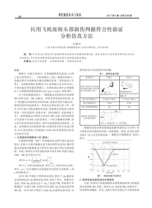
方法的可行性。
1 头部损伤判据概述(HIC 概述)
头部损伤判据 (HIC) 在座椅取证过程中进行 动 态试
验时 ,若 假 人头 部 可能 撞 击 到 飞 机 内 部 任 何 设 备,都 必 须
通过 采 集 相 应 数 据 通 过 计 算 得 出 HIC 值 以 评 估 头 部 的 损
伤。目前,各国局 方均在适航条款中要求 HIC 的值不超过
中国民航局等民航管理部门,在颁布的法规中已明确规
定了头部损伤判据的标准(head injury Criteria,简称 HIC)。
对于民机制造商而言,一般都通 过 试验 验 证民 机 座椅
HIC 的 符 合性。 HIC 试验 是 一项 技 术要 求 较 高 的 试 验 ,由
于 飞 机 舱 内 环 境 的 复 杂 性 和 HIC 试 验 结 果 的 不 确 定 性 ,
计 完 成 即 可 对 HIC 试 验 结 果 有 一 个 较 为 精 确 的 判 断 ,将
大量节省时间 和经济成本,提升民机座椅研发的效率。目
前, 各 国 都 在 对 民 机 座 椅 HIC 试 ห้องสมุดไป่ตู้ 仿 真 分 析 方 法 进 行 研
究 ,FAA 更 是 颁 布 了 咨 询 通 告 AC20-146 来 说 明 相 关 仿 真
目前,各国都在针对动态试验进行大量的研究工作。 FAA 于 2003 年颁布了 AC20-146 咨询通告,阐述针对座 椅 动态 试 验 可以 采 用的 方 法 。 FAA 认 为 ,目 前 经 验 证 ,计 算 机有限元仿真软件在一定限制条件下可以代替座椅动态 试 验 。前 市 场 上 类 似 的 仿 真 分 析 软 件 种 类 繁 多 ,受 限 于 篇 幅 , 本 文 着 重 介 绍 其 中 一 种 FAA 认 为 可 以 运 用 的 软 件 MADYMO 。
气囊式无人机缓冲系统的着陆侧翻现象

( UAV ) wi t h he t a i r b a g c u s h i o n s y s t e ms . F i r s t l y , a d y n a mi c mo d e l o f l a n d i n g i mp a c t o f t h e UA V i s e s t a b l i s h e d , a n d
关 键词 缓 冲着 陆 气 囊 仿 真 侧翻 无人机 文 献标 志码 : A 文章 编号 : 1 0 0 9 — 8 5 1 8 ( 2 0 1 3 ) 0 1 — 0 0 2 1 — 0 8 中图分 类号 : V2 4 4 . 1 1
D OI : 1 0 . 3 9 6 9 / j . i s s n . 1 0 0 9 - 8 5 1 8 . 2 0 1 3 . 0 1 . 0 0 3
t h e t u r n - o v e r p h e n o me n n a i s p r o p o s e d . F i n a l l y , t h e e v a l u a t i o n f o r t h e s c h e me i s g i v e n b y s i mu l a t i o n a n a l y s i s . T h e
第3 4 卷第 1 期
2 0 1 3 年 2 月
毫米波人体成像技术在机场安检中的应用

毫米波人体成像技术在机场安检中的应用1. 引言1.1 背景介绍毫米波人体成像技术是一种通过毫米波辐射对人体进行成像的先进技术,具有快速、非接触式、隐私性高等特点。
随着恐怖袭击和犯罪事件的频发,加强机场安检已成为各国政府的重要任务之一。
传统的机场安检方式存在着诸多弊端,例如效率低下、安全风险大、隐私权受到侵犯等问题。
毫米波人体成像技术由于其高效、无损、隐私性好的特点,被广泛应用于机场安检领域,成为提升安检效率、保障安全的重要手段之一。
毫米波人体成像技术能够以高清晰度获取被检测人体的图像,并能够在图像中发现隐藏在衣物下的潜在威胁物品,如枪支、刀具等。
相较于传统的金属探测器和手持金属探测棒,毫米波人体成像技术能够更准确地识别携带危险物品的人员,大大提高了安检的效率和准确性。
该技术在保障乘客隐私的也有效减少了人工巡检的复杂性和主观性,提升了安检的一致性和公正性。
在全球范围内,越来越多的机场开始引入毫米波人体成像技术,以应对恐怖主义威胁和犯罪行为,保障民众的生命财产安全。
随着技术的不断升级和完善,毫米波人体成像技术在机场安检中的应用前景将会更加广阔。
1.2 目的意义毫米波人体成像技术在机场安检中的应用,旨在提高安检效率、加强安全性保障,同时平衡技术优势与隐私保护之间的关系。
在传统安检手段下,存在着安检效率低、安全隐患大等问题,而毫米波人体成像技术的引入可以有效解决这些问题,提升安检工作效率,确保航空出行的安全性和畅通性。
其技术优势在于能够实现无接触全身扫描、快速发现潜在危险物品等,使安检过程更加简便快速。
同时也面临着隐私保护不足、法律规定不完善等问题,需要加强相关隐私保护措施和制定法规规范。
通过深入探讨毫米波人体成像技术在机场安检中的应用,在有效提升安检效率的也需要充分考虑安全性与隐私保护之间的平衡,以确保技术的可持续发展和社会的健康发展。
对未来技术的前景展望和安检效率提升、安全性保障等方面的探讨,也具有重要的现实意义和指导作用。
美军装备M21自动化学药剂报警器 可部署到单兵
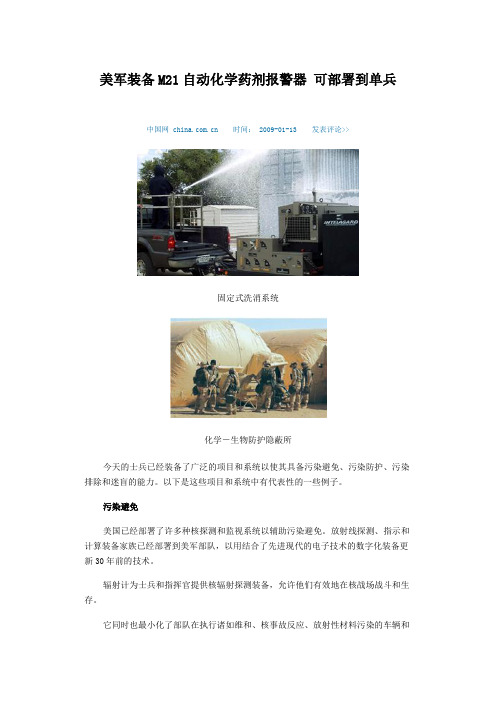
美军装备M21自动化学药剂报警器可部署到单兵中国网 时间: 2009-01-13 发表评论>>固定式洗消系统化学-生物防护隐蔽所今天的士兵已经装备了广泛的项目和系统以使其具备污染避免、污染防护、污染排除和迷盲的能力。
以下是这些项目和系统中有代表性的一些例子。
污染避免美国已经部署了许多种核探测和监视系统以辅助污染避免。
放射线探测、指示和计算装备家族已经部署到美军部队,以用结合了先进现代的电子技术的数字化装备更新30年前的技术。
辐射计为士兵和指挥官提供核辐射探测装备,允许他们有效地在核战场战斗和生存。
它同时也最小化了部队在执行诸如维和、核事故反应、放射性材料污染的车辆和装备的恢复等和平时期任务时暴露在核辐射下的危险。
AN/UDR-13辐射仪是一个结构紧凑的、手持式、口袋大小战术辐射计。
能测量和显示战场环境中微量和总的核累积剂量。
按钮式键盘可以进行模式选择、功能控制和剂量率及任务剂量声音和可视报警门限值的设定。
能自动唤醒的“睡眼”模式可以处长电池的使用时间。
液晶显示提供数据输出和警报模式信息。
作为老式IM-93/PP-1578和UDR-13辐射仪的替代者,它改进了敏捷剂量测量(包括中子、报警和比率测量)、反显显示和稳定读数与校准。
它不需要单独的充电器。
AN/VDR-2辐射仪从辐射微尘和放射性同位素探测核辐射,用于代替老式IM-174和AN/PDR-27,能够以手持式方式在车上或下车执行地面放射性调查。
该装置也能提供定量的放射性测量以帮助人员、装备和供给品的净化行动。
该辐射仪的组件包括IM-243辐射计仪表。
DT-616探针和一个用皮带捆扎的小袋。
成套工具在各式军用车辆内是通用工作台上的允许项目,辐射测量仪正可以安装在这上面。
该辐射仪包括一个能与装甲车内的车载核-生-化保护系统兼容的声音和/或视频报警信号,而且它还可以和车载电力系统和通信系统交互。
AN/PDR-75辐射仪测量敏感和残余的贮存在DT-236独立放射量测定器中从1厘戈瑞到100厘戈瑞的伽马射线和中子射线剂量。
飞行人员特发性面神经麻痹临床观察

2 李魁梧 , 李旭 东, 于传久 .飞行 员跟腱 断裂 5例 [ ] J .航
飞行 人 员 特 发 性 面 神 经 麻 痹 临床 观 察
周府伯 赵 学武 ,
(.0 12 8医院4 1临床 部 , 6 吉林 长春 10 2 ;. 37 30 129 15部队医院 , 吉林 长春 10 5 ) 30 1
m 管痉 挛 , 导致茎乳孔内面神经发 炎和水肿 有关 。本文 就 20 2 1 年来我 院收治 的 5例飞行人员病人 , 0 6— 0 1 报道如
下。 1 资 料 与 方 法
促进神经机能恢 复 为主 。给予 生理盐 水 10mL 地塞 0 加 米松 1 g 1A/ 静 滴 , 0m , d 1—2周 后 改 为 强 的 松 片 3 吕 Om
眼、 齿 、 腮 和 吹 口哨 , 项 5 露 鼓 每 0次 , 3次/ ; 部 肌 肉 按 d面
2. 96岁 ; 飞行时问 80~240mi, 种为 强五 2例 、 七 0 0 n 机 歼 1 、 例 教八 1 、 例 初教 六 1例 。病后 1— A 院 , 断为 右 4d 诊 侧特发性面神经麻痹 2例 , 左侧 3例。 12 临床表现 . 于清晨起床 后或被 他人突然 发现一侧 面 颊活动不灵 、 口角歪斜 ; 侧面部 表情肌瘫 痪 , 病 前额皱纹 消
摘要
目的 : 一步探讨 飞行人 员特发 性 面神 经麻 痹的 治疗措施 。方 法 : 进 选择 以糖 皮质 激素 为主的 综合 治 疗。
结果 : 5例病人平均3 . 达到临床治愈 。结论 : 54d 以糖皮质激素为主的综合治疗 5例飞行人 员特 发性 面神 经麻 痹
获 得 良好 效 果 。 关键词 特 发 性 面神பைடு நூலகம்经麻 痹 ; 飞行 人 员 文 献标 识码 :B 文 章 编 号 :2 9 0 5—13 .0 20 . 1 4 4 2 1. 90 3 中图 分 类 号 :R 5. 8 8 6 7
应用硬膜外电刺激的方法[发明专利]
![应用硬膜外电刺激的方法[发明专利]](https://img.taocdn.com/s3/m/c35da2511a37f111f0855b1f.png)
专利名称:应用硬膜外电刺激的方法
专利类型:发明专利
发明人:S.J.哈克马,Y.陈,C.安杰利,C.休布舍尔,M.拉维申请号:CN201680059689.2
申请日:20160818
公开号:CN108136182A
公开日:
20180608
专利内容由知识产权出版社提供
摘要:本发明的实施方案涉及应用硬膜外电刺激以改善瘫痪单独中的运动功能或生理反应的方法。
更具体地,本发明涉及创建和应用硬膜外刺激的特定配置以辅助或引起患者进行复杂运动或以减轻瘫痪的一种或多种继发性后果的方法,所述继发性后果包括但不限于心血管、呼吸、膀胱、温度和性功能障碍。
申请人:路易斯维尔大学研究基金会公司
地址:美国肯塔基州
国籍:US
代理机构:北京市柳沈律师事务所
代理人:张文辉
更多信息请下载全文后查看。
直升机飞行头盔热影响因素分析
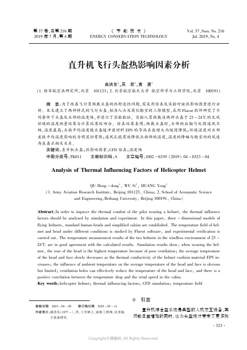
第37卷,总第216期2019年7月,第4期《节能技术》ENERGY CONSERVATION TECHNOLOGYVol.37,Sum.No.216Jul.2019,No.4直升机飞行头盔热影响因素分析曲洪东1,吴思2,黄勇2(1.陆军航空兵研究所,北京101123;2.北京航空航天大学航空科学与工程学院,北京100191)摘要:为了改善飞行员佩戴头盔的热舒适性问题,需采用仿真及实验对该热影响因素进行分析。
本文建立了两种样式的飞行头盔、标准人头及简化舱室的三维模型,采用Fluent软件研究了不同条件下头盔及头部的温度场,并进行了实验验证。
实验人员佩戴这两种头盔于23~24℃的无风环境的温度测量结果与计算结果较吻合。
仿真结果表明:佩戴头盔时,头部的后脑勺处因通风不畅,温度最高;头面平均温度随头盔缓冲层材料EPS的导热系数增大而缓慢降低;环境温度对头部皮肤平均温度影响较为明显但有限;通风孔能有效降低头面部的温度,温度的降幅与舱室内的风速存在着正相关关系。
关键词:直升机头盔;热影响因素;CFD仿真;温度场中图分类号:TK011文献标识码:A文章编号:1002-6339(2019)04-0323-04Analysis of Thermal Influencing Factors of Helicopter HelmetQU Hong-dong1,WU Si2,HUANG Yong2(1.Army Aviation Research Institute,Beijing101123,China;2.School of Aeronautic Scienceand Engineering,Beihang University,Beijing100191,China)Abstract:In order to improve the thermal comfort of the pilot wearing a helmet,the thermal influence factors should be analyzed by simulation and experiment.In this paper,three-dimensional models of flying helmets,standard human heads and simplified cabins are established.The temperature field of hel⁃met and head under different conditions is studied by Fluent software,and experimental verification is carried out.The temperature measurement results of the two helmets in the windless environment of23~ 24℃are in good agreement with the calculated results.Simulation results show:when wearing the hel⁃met,the rear of the head is the highest temperature because of poor ventilation;the average temperature of the head and face slowly decreases as the thermal conductivity of the helmet cushion material EPS in⁃creases;the influence of ambient temperature on the average temperature of the head and face is obvious but limited;ventilation holes can effectively reduce the temperature of the head and face,and there is a positive correlation between the temperature drop and the wind speed in the cabin.Key words:helicopter helmet;thermal influencing factors;CFD simulation;temperature field收稿日期2019-04-20修订稿日期2019-05-11作者简介:曲洪东(1977~),男,工学硕士,高级工程师,从事航空装备研究。
雷达吸波涂层损伤及修复研究进展
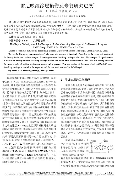
雷达吸波涂层损伤及修复研究进展*杨亮,王亦菲,张彦素,吕玉泽(国防科学技术大学航天与材料工程学院,湖南长沙410073)摘要:介绍了雷达吸波涂层的工作原理,依据隐身武器装备使用过程中引起损伤状况的原因和损伤部位对雷达吸波涂层的损伤进行分类,并通过理论计算不同机械损伤面积对吸波涂层隐身性能变化。
总结了目前美军对隐身武器装备雷达吸波涂层维修的措施和经验。
为适应战场抢修的要求提出了研发工艺简单、使用方便、容易调节快速固化隐身涂层的修复思路。
关键词:雷达吸波涂层;损伤;修复中图分类号:T B34文献标志码:AThe Repair Technique and the Damage of Radar Absorbing Coatings and I ts Research ProgressYANG Liang,WANG Yifei,ZH ANG Yansu,LV Yuze(College of Aerospace and Material Engineering,National University of Defense Technology,Changsha410073,China) Abstr act:In this paper,the mechanism of r adar absor bing coatings is described.Accor ding t o the reason and location of the damage in the cour se of the weapon,the damage of radar absorbing coatings is classified.The change of the performance of mechanical damage of radar absorbing coat ings is calculated on the basis of t he theoret ic.The t echnique and experience of the r epair to radar absorbing coatings ar e summar ized at pr esent.The new method of the repair which quick2solidify r adar absor bing coatings is studied is developed as well for the requir ement of battlefield r epair.Key wor ds:radar absorbing coatings,damage,r epair隐身技术始于第二次世界大战,起源德国,发展于美国,在英、法、日、俄等发达国家得到了进一步发展应用,对于提高现代兵器的突防能力与生存能力发挥着重要的作用,引起世界各军事大国的高度重视。
飞艇气囊压力与蒙皮张力的估算

飞艇气囊压力与蒙皮张力的估算
飞艇气囊压力与蒙皮张力的估算
平流层飞艇的研制开发近年来成了世界各国的研究热点,由于平流层飞艇的滞空高度高,在上升和下降时飞艇气囊的体积和压力变化动态范围很大,其气囊的设计与低空飞艇有很大的不同.为了给飞艇的气囊结构设计、强度设计提供依据,采用微元受力分析的方法,对气囊蒙皮内张力的进行了分析,得出了飞艇气囊内外压差、曲率半径、气囊蒙皮内张力的关系.该关系还可以应用于各种充气囊体的张力分析,并利用此关系对飞艇的蒙皮张力进行了计算.
作者:王文隽李勇姚伟郑威 WANG Wen-jun LI Yong YAO Wei ZHENG Wei 作者单位:中国空间技术研究院研究发展中心,北京,100080 刊名:宇航学报ISTIC PKU英文刊名:JOURNAL OF ASTRONAUTICS 年,卷(期):2007 28(5) 分类号:V265+.2 关键词:平流层飞艇气囊张力气压。
【CN109823508A】超限热防护与生存状态感知的高速飞行器柔性蒙皮【专利】
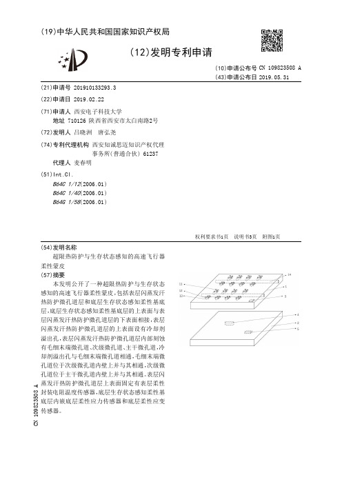
(19)中华人民共和国国家知识产权局(12)发明专利申请(10)申请公布号 (43)申请公布日 (21)申请号 201910133293.3(22)申请日 2019.02.22(71)申请人 西安电子科技大学地址 710126 陕西省西安市太白南路2号(72)发明人 吕晓洲 唐弘尧 (74)专利代理机构 西安知诚思迈知识产权代理事务所(普通合伙) 61237代理人 麦春明(51)Int.Cl.B64C 1/12(2006.01)B64C 1/40(2006.01)B64G 1/58(2006.01)(54)发明名称超限热防护与生存状态感知的高速飞行器柔性蒙皮(57)摘要本发明公开了一种超限热防护与生存状态感知的高速飞行器柔性蒙皮,包括表层闪蒸发汗热防护微孔道层和底层生存状态感知柔性基底层,底层生存状态感知柔性基底层的上表面与表层闪蒸发汗热防护微孔道层的下表面相接,表层闪蒸发汗热防护微孔道层的上表面设有冷却剂溢出孔,表层闪蒸发汗热防护微孔道层内部刻蚀有毛细末端微孔道、次级微孔道、主干微孔道,冷却剂溢出孔与毛细末端微孔道相通,毛细末端微孔道位于次级微孔道内壁上并与其相通,次级微孔道位于主干微孔道内壁上并与其相通。
表层闪蒸发汗热防护微孔道层上表面固定有表层柔性封装电阻温度传感器,底层生存状态感知柔性基底层内嵌底层柔性应力传感器和底层柔性应变传感器。
权利要求书1页 说明书3页 附图1页CN 109823508 A 2019.05.31C N 109823508A1.超限热防护与生存状态感知的高速飞行器柔性蒙皮,其特征在于,包括表层闪蒸发汗热防护微孔道层(1)和底层生存状态感知柔性基底层(2),所述底层生存状态感知柔性基底层(2)的上表面与表层闪蒸发汗热防护微孔道层(1)的下表面相连接。
2.根据权利要求1所述的超限热防护与生存状态感知的高速飞行器柔性蒙皮,其特征在于,所述表层闪蒸发汗热防护微孔道层(1)和底层生存状态感知柔性基底层(2)的材质是柔性聚合物。
飞行员面部面罩密封域的数据测量与特征分析
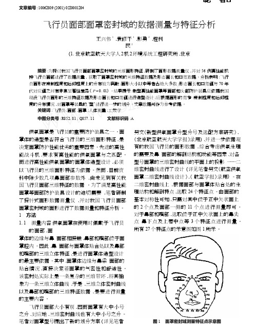
·论著·文章编号:10062809 (2001) 022*******飞行员面部面罩密封域的数据测量与特征分析王兴伟1 ,袁修干1 ,彭勇2 ,程利民2(1 .北京航空航天大学人2机2环境系统工程研究所,北京100083 ;摘要:为探讨我国飞行员面部面罩密封域的三维面形特征,研制了面形数据测量仪,并对56 例高性能机种飞行员面部进行了数据测量, 获取了面罩密封域的三维特征数据及形态面长和口宽数据。
分析表明:飞行员面形在瘦削程度和后仰程度上的分布较为离散;面形大小以中等者占绝大多数;形态面长和口宽值与70 年代对应值之间有非常显著性差异( P < 0. 01) 。
结果提示:新型高性能面罩等面部和头部防护装具应依据我国现役飞行员面形的三维特征数据及形态面长和口宽值进行造型设计; 应根据面形的宽窄、瘦削程度和后仰程度的分布情况,对面罩等装具的“型”进行进一步的划分。
文章数据可作为参考依据。
关键词:飞行员;面部;面罩;人体测量;工效学中图分类号: R852. 81 ; Q857. 11 文献标识码:A供氧面罩是飞行员的重要防护装具之一。
面罩体的造型是否符合飞行员的三维面形特征,是决定面罩防护性能优劣的重要因素。
先进的高性能战斗机, 要求有高性能的供氧面罩与之匹配。
而进行高性能供氧面罩的面罩体造型设计,必须以飞行员的三维面形特征为依据。
然而,目前资料中除少数几项鼻面部参数外,尚未见到有关我国飞行员面部三维特征的数据。
为了满足高性能面罩等面部防护装具设计的迫切需要,笔者研制了探针式面形数据测量仪,并对我国飞行员面部面罩密封域的面形进行了数据测量和特征分析。
1 方法1 . 1 测量内容供氧面罩在使用时佩戴于飞行员的面部,面罩体的边缘与鼻、面部相接触,鼻部和嘴部位于面罩腔内。
因此,鼻、面部与面罩体贴合处以及鼻部和嘴部的三维立体特征,是进行面罩体造型设计的最主要依据。
其中,面罩体边缘与鼻梁、面部的贴合情况, 直接决定着面罩的气密性和舒适性。
亚低温治疗对重型颅脑损伤患者预后及其脑脊液中Aβ水平的影响

亚低温治疗对重型颅脑损伤患者预后及其脑脊液中Aβ水平的影响申亚峰;涂悦;程世翔;孙洪涛;张赛【摘要】目的观察亚低温治疗对重型颅脑损伤(sTBI)患者预后及其脑脊液(CSF)中β淀粉样蛋白(Aβ)水平的影响,并探讨其意义.方法将60例sTBI随机分为观察组和对照组各30例,观察组采用亚低温治疗,对照组采用常温治疗;采用双抗体夹心ELISA法检测治疗前及治疗后第1、3、5、7天患者CSF中的Aβ,3个月后行GOS评定预后.结果对照组CSF中的Aβ水平逐渐升高,而观察组Aβ水平逐渐降低;治疗后3、5、7 d,两组AB水平比较,P均<0.01.治疗后3个月观察组GOS为(4.3±0.4)分,对照组为(2.2±0.2)分,两组比较,P<0.05.结论亚低温治疗可明显改善sTBI患者的预后,可能与其降低患者CSF中的Aβ水平有关.%Objective To study the effects of moderate hypothermia on cerebrospinal fluid amyloid β(Aβ)peptide le vel and prognosis in severe traumatic brain injury (sTBI)patients. Methods 60 sTBI patients were randomly divided into observe group and control group,30 cases each. Patient in observe group were treated with moderate hypothermia. Aβ in cerebrospinal flui d was detected by ELISA at 1、3、5、7 days, and prognosis were evaluated by GOS. Results Aβ in cerebrospinal fluid increased time-dependent in control group , but decreased time-dependent in observe group. GOS scroll was 4.3 ± 0.4 in observe group, and 2.2 ± 0.2 in control group ( P <0.05 ). Conclusion Moderate hypothermia can inhabite the expression of Aβ and improve the clinical prognosis.【期刊名称】《山东医药》【年(卷),期】2011(051)002【总页数】2页(P1-2)【关键词】重型颅脑损伤;亚低温疗法;脑脊液;β淀粉样蛋白【作者】申亚峰;涂悦;程世翔;孙洪涛;张赛【作者单位】天津医科大学研究生院,天津,300070;武警医学院附属医院;武警医学院附属医院;武警医学院附属医院;武警医学院附属医院;武警医学院附属医院【正文语种】中文【中图分类】R651.1大量研究表明,亚低温技术具有显著的脑保护作用,并能抑制损伤后某些损伤因子的生成及释放,有利于防止继发损害,可显著降低重型颅脑损伤(sTBI)患者的病死率[1~3],且无明显不良反应。
运用TEM模型对中国民航冲偏出跑道事件的分析
运用TEM模型对中国民航冲偏出跑道事件的分析威胁差错管理(TEM模型)是一种针对不安全事件中环境、航空器状况、人的表现等因素的分析模型,它是人为因素知识在实践中的综合应用,能深入改进航空器运行安全裕度,是一种有效的安全分析工具。
多数不安全事件都是在威胁、差错两者的共同作用下发生的。
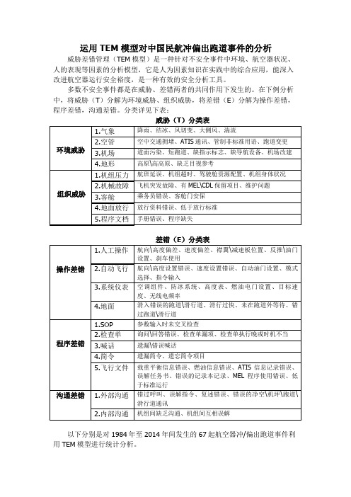
在下例分析中,将威胁(T)分解为环境威胁、组织威胁,将差错(E)分解为操作差错,程序差错,沟通差错。
分类详见下表:威胁(T)分类表差错(E)分类表以下分别是对1984年至2014年间发生的67起航空器冲/偏出跑道事件利用TEM模型进行统计分析。
一、冲/偏出跑道事件威胁因素分析对1984年至2014年间发生的67起航空器冲/偏出跑道事件进行分析,在67起事件中,威胁(T)因素统计如下图:环境威胁组织威胁通过对威胁因素的分析,可见复杂气象条件、机场硬件不足是造成飞机冲/偏出跑道事件的首要威胁:1)在人为无法改变复杂气象条件的情况下,要减少冲/偏出跑道事件的发生,就要从机组安全意识方面着手,加强安全教育,要求每一名飞行人员都能严格按照CCAR-91部《一般运行和飞行规则》要求执行飞行任务,坚决贯彻“八该一反对”规定,杜绝盲目蛮干,杜绝侥幸心理。
2)航空公司应梳理所有在特殊机场、复杂机场航线运行的航班,进行充分的风险评估,并制定相应风险管控措施,在执行航班前对飞行员进行适当预警,让飞行员能对存在的风险做好提前准备。
3) 对于机场硬件条件不足的机场,如缺少跑道中心线指引灯,缺少能见度测试仪,高高原跑道长度较短的机场,建议应加大经济投入,尽快完成设施设备加改装。
民航各单位都应牢固树立起安全是潜在效益的观念,通过做好安全工作来促进经济效益的提高。
二、冲/偏出跑道事件差错因素分析对1984年至2014年间发生的起航空器冲/偏出跑道事件进行分析,在67起事件中,差错(E)因素统计如下图:操作差错程序差错沟通差错通过对差错因素统计,可见操作差错是造成飞机冲/偏出跑道事件差错因素中占比最高的,这反映出飞行员在操作技能和飞行作风方面都存在着不足。
- 1、下载文档前请自行甄别文档内容的完整性,平台不提供额外的编辑、内容补充、找答案等附加服务。
- 2、"仅部分预览"的文档,不可在线预览部分如存在完整性等问题,可反馈申请退款(可完整预览的文档不适用该条件!)。
- 3、如文档侵犯您的权益,请联系客服反馈,我们会尽快为您处理(人工客服工作时间:9:00-18:30)。
Ping He Graduate University of ChineseAcademy of Sciences,Beijing,100190,China; Institute of Engineering Thermophysics, Chinese Academy of Sciences,Beijing,100190,China e-mail:heping@Zhigang Sun e-mail:sunsonofjilin@Baoting Guo e-mail:guobt@Haisheng Chen e-mail:chen_hs@Chunqing Tane-mail:tan@ Institute of Engineering Thermophysics, Chinese Academy of Sciences,Beijing,100190,China Aerothermal Investigation of Backface Clearance Flow in Deeply Scalloped Radial TurbinesA numerical investigation offlow structure and heat transfer in the backface clearance of deeply scalloped radial turbines is conducted in this paper.It is found that the leakage flow is very strong in the upper radial region whereas in the lower radial region,the scrapingflow dominates over the clearance and a recirculation zone is formed.Pressure distributions are given to explain theflow structure in the backface clearance,and it is found that due to the sharp reduction of radial velocity and Coriolis force,the pressure difference in the lower radial region is reduced drastically,which is the mechanism for the domination of the scrapingflow and the corresponding recirculation zone.There are two high heat transfer coefficient zones on the backface surface.One is located in the upper radial region due to the reattachment of the leakageflow and the other is located in the lower radial region caused by the impingement of the scrapingflow.Increase of the clearance height reduces the high heat transfer coefficient caused by the impingement of the scrapingflow,although it increases the leakage loss.On the other hand,the high heat transfer coefficient in the upper radial region can be reduced remarkably by using the suction side squealer geometry.[DOI:10.1115/1.4006664]1IntroductionRadial turbines have established prominence in thefield of small turbomachinery because of their simplicity,low cost,rela-tively high performance,and favorable installation features[1]. Deeply scalloped radial turbine rotors"scallop"their disk to reduce weight and minimize centrifugal stress.Meanwhile,the highest stress in deeply scalloped radial rotors occurs at locations where the metal temperature is considerably lower than at rotor inlet[2].With these significant advantages,deeply scalloped ra-dial turbines are widely used in microturbines and small turboma-chinery;examples are the radial turbines for the Capstone production series,the NASA high temperature radial turbine for a small engine[3],and the NASA-PW compact radial turbine[4]. As shown in Fig.1,the disk of deeply scalloped radial turbine rotors does not extend out to the blade tip,and the blades have both the tip clearance and the backface clearance in the inlet sec-tion(Fig.2).The backface clearance in deeply scalloped radial turbines causes two additional problems compared with traditional ones.Firstly,the backface clearance leakageflow decreases the blade loading and interacts with the mainstream and secondary flows in the blade passage,which result in lower turbine effi-ciency.Secondly,the blade backface is subjected to relatively high thermal loads due to the high velocity,thin boundary layer, and high temperature associated with the backface leakageflow. The backface leakageflow separates and reattaches in the clear-ance,which leads to a more complicatedflowfield.What is worse,the root of the blade backface is one of the life-limiting regions for radial turbine rotors because of the high centrifugal stress[1],which makes the high thermal loads of the blade back-face more undesirable(in contrast,the blade tip is also subjected to high thermal loads,while the centrifugal stress is extremely low).These two factors greatly affect the efficiency and durability of radial turbines.The backface clearance is usually the largest clearance in deeply scalloped radial turbines,hence,the corresponding loss is considerable.Simonyi et al.[5]presented a comparison of a quasi-3D analysis and experimental performance for three deeply scalloped radial turbines.A hub clearance model was used to eval-uate the influence of the backface clearance.It was found that the efficiency penalty due to the backface clearance was nearly60% of the total clearance losses.A similar conclusion was also drawn by Tirres[6]when he predicted the performance of the solid ver-sion of a cooled radial rotor,and it was shown that the backface clearance loss for the rotor accounted for79%of total clearance losses.Rogo[7]summarized the clearance losses in radial tur-bines as a function of normalized clearance height,the turbine ef-ficiency decreased by0.17%with increasing the normalized backface clearance height by1%.However,there is little literature concerning the detailedflow structure in the backface clearance.Zangeneh et al.[8]analyzed theflow structure in radial turbines.The authors derivedan Fig.1Deeply scalloped radial turbine rotors:(a)turbine A and (b)turbine BContributed by the International Gas Turbine Institute(IGTI)of ASME for publi-cation in the J OURNAL OF T URBOMACHINERY.Manuscript received July28,2011;final manuscript received December4,2011;published online October31,2012.Assoc. Editor:Ricardo F.Martinez-Botas.expression for the generation of vorticity in a rotating coordinate. The blade passage was then divided into three sections according to the expression and three different types of secondaryflows were shown in the rotor.Heidmann et al.[9]investigated the blade surface pressure and outletflowfield of a deeply scalloped radial turbine.The authors found that the simulation results with backface clearance agreed better with the experimental data.A similar result was also found by Larosiliere[10],who used a back-face clearance model to simulate the backface clearanceflow in a deeply scalloped radial turbine.The author presented entropy con-tours and velocity vectors at different quasi-normal planes,and showed the backface clearance leakage vortex.Nevertheless,the flow structure in the backface clearance cannot be simulated by using a clearance model.Cox et al.[11]studied theflow around the scallops of a mixed-flow turbine for turbochargers;the authors indicated that the presence of scallops introduced a forward-facing step to the inletflow,which resulted in a stronger passage vortex and lower efficiency.But the turbine was just scalloped a little,and the investigated region was more like a backface cavity instead of a backface clearance.A numerical study was performed by He et al.[12],who investigated theflow and loss in deeply scalloped radial turbines.Meshes were generated in the backface clearance region to study the backface clearanceflows.It was illustrated that the backface clearance leakage vortexflowed towards the blade tip under the influence of spanwise secondary flow and centrifugal force,which resulted in a large mixing loss. However,the study focused on the backface clearanceflow in the blade passage and theflow structure in the backface clearance was not further discussed.Heat transfer on turbine blade clearances has been a hot topic over the past decades,and most of the works focused on the tip clearance in axial turbines.Bunker[13]presented a detailed review of both numerical and experimental researches on turbine blade tip heat transfer from1955to2000.An early experimental study on blade tip heat transfer conducted by Mayle et al.[14]indicated that the heat transfer coefficient on the blade tip was mainly determined by the pressure-driven tip clearanceflow and was independent of the relative motion between blade and casing wall.Heat transfer on a typical blade tip of power generation gas turbines was experimen-tally studied by Bunker et al.[15],and a complex distribution of heat transfer on the blade tip was observed.There was a sweet spot of low heat transfer that extended into the midchord region within the thickest portion of the tip.And a pressure side entry vortex caused a significant enhancement to heat transfer aft of the sweet spot.Detailed heat transfer behavior of both theflat and squealer tips was experimentally studied by Azad et al.[16,17].It was found that the heat transfer coefficient on the blade tip increased with increasing the clearance height and turbulence intensity,and the overall heat transfer on the blade tip was reduced by using squealer tips.Kwak et al.[18]measured the heat transfer coefficient on the blade tip,shroud,and pressure and suction surfaces for different squealer geometries.It was indicated that the squealer tips signifi-cantly reduced the overall heat transfer and the suction side squealer tip had the lowest heat transfer coefficient among the squealer geometries.Heat transfer coefficient measurements on the blade tip and near tip region conducted by Newton et al.[19] revealed that the highest levels of heat transfer were located where theflow reattached on the tip surface,and high heat transfer was also found on the suction surface,onto which the tip leakage vortex impinged.Heat transfer of a full-scale rotating turbine tip was measured by Dunn et al.[20].The highest Nusselt number was measured just aft of the leading edge lip on the tip cavity surface due to theflow reattachment.Numerical investigations play an important role in the study of heat transfer by providing detailedflow structure and heat transfer results.Mumic et al.[21]presented a comparison of simulation results and experimental data[16,17]of heat transfer on blade tips. The predicted heat transfer for both theflat and squealer tips agreed well with the experimental data.Krishnababu et al.[22,23]per-formed numerical studies offlow and heat transfer on blade tips. The authors presented complex separation and reattachment of leak-age vortex to explain the distribution of heat transfer coefficient in the clearance.It was also shown that the calculation results using the shear stress transport(SST)turbulence model was in close agree-ment with the experimental data[19].Molter et al.[24]presented a comparison of simulation and measurement results in a rotating tur-bine tip.The authors indicated that the computationalfluid dynamics (CFD)calculation did capture the measured heatflux trends in the tip region,although it generally overpredicted the overall heatflux. There were many other studies focused on the heat transfer in axial turbine blade tips,and the detailed review can be seen in Ref.[25]. However,there is little literature concerning the detailed heat transfer in the backface clearance of deeply scalloped radial tur-bines.Heuer et al.[26,27]conducted a comprehensive investiga-tion on the heat transfer of a turbocharger using a conjugate heat transfer method.The authors presented detailed temperature and Nusselt number distributions on the blades.The thermal and cen-trifugal stresses at steady and transient states were also analyzed. It provides a good reference for the current study.This paper presents a numerical investigation offlow structure and heat transfer in the backface clearance of deeply scalloped ra-dial turbines.And the influences of clearance height and squealer geometry are also discussed.2Numerical MethodThree turbines(turbine A,turbine B,and turbine C)are ana-lyzed in this paper.Turbine A(Fig.1(a))is for detailed study;tur-bine B(Fig.1(b))and turbine C are for CFD verification.Turbine A is a deeply scalloped radial turbine designed for a microturbine, turbine B is a deeply scalloped radial turbine designed by PW Company for a small engine[4],and turbine C[16]is a linear cas-cade with the blade tip profile of GE-E3gas turbine rotor blades. The parameters for turbine A and B are shown in Table1. Figure2presents the meridional view for turbine A and both the tip and backface clearances are shown.In Fig.2,the interface of the backface clearance and the backface cavity regions,which are located near the region of RL¼0%,is assumed to be a“wall.”This is often true in experimental conditions,where the sealing of the turbine backface is perfect and the backface cavityflow rate is ignored.However,in real engine conditions,sealingflows($1% Fig.2Meridional view of theflow passage for turbine Aof the mainstream mass flow [7])must be channeled from the compressor to prevent hot gas ingestion.This paper focuses on the nonsealing flow condition and the influence of the sealing flow on the backface clearance flow,especially near the region of RL ¼0%,will be the next step of the study.The squealer tip is widely used in axial turbines,and it can reduce the thermal loads for the turbine blade tip as mentioned in the above references.However,the effect of the possible squealer geometries on the heat transfer of blade backface surface is not yet clear.Figure 3shows the three squealer geometries for the blade backface in this paper.They are pressure side squealer (PSS),suction side squealer (SSS),and pressure and suction side squealer (PS þSS),respectively.Structured meshes are generated using ANSYS-ICEM,a com-mercial mesh generation software.The computational domain con-sists of a single stator and rotor for turbine A and B and a single blade for turbine C with periodic boundaries.Meshes are generated in the backface clearance region to obtain the detailed flow struc-ture where the average Y þis less than 1.To ensure mesh independ-ence,the flat backface case requires $1.9Â106cells,the squealer backface case $3.8Â106cells for turbine A.The detailed cell sta-tistics are summarized in Table 2and the meshes are shown in Fig.4(a coarse mesh is used for better visualization).A commercial solver software,ANSYS-CFX,is used to per-form the calculations,and the solutions are obtained by solving Navier–Stokes equations.For turbine A and B,total pressure and total temperature are specified at the stator inlet along with a ra-dial flow angle (0deg)and medium turbulence intensity (5%).At the rotor outlet,static pressure is specified.A rotational periodic boundary condition is imposed on the periodic boundaries.The connection option of the stator and rotor domains is “stage,”which performs a circumferential averaging of the fluxes through bands on the stator and rotor domain interface.The isothermalwall condition is imposed on the blade surfaces with 75%of inlet total temperature for the calculation of heat transfer coefficients.Although the heat transfer coefficient may vary with different given wall temperatures,the distribution trends are the same.And the constant temperature wall condition was widely used in the calculation of heat transfer for tip clearance [21–24,28].ATable 1Parameters for the two turbinesTurbine ATurbine B Tt 0,K 1150477.8Pt 0,kPa375.6333.7Mass flow,kg/s 2.08 2.71Rotor speed,rpm 4500019919Pt 0/Pt 2 3.51 4.99Ps 2,kPa9652Work factor (D h/Ut 2)0.92 1.10Rt ,mm 125183.6Rs/Rt0.640.68Blade tip passage span,mm 2013.4Tip clearance at inlet,%64Tip clearance at outlet,%0.80.46BC ,%8 2.5Stator number/Rotor number23/1336/14Fig.3Different squealer geometries for turbine A:(a )PSS,(b )SSS,and (c )PS 1SSTable 2Cell statistics for the three turbines Turbine A (Flat)Turbine A (SSS)Turbine B Turbine C Stator 0.6M 0.6M 0.6M —Rotor 1.3M 3.2M 1.3M 1.5M Total1.9M3.8M1.9M1.5MFig.4Meshes for the three turbines:(a )turbine A,(b )turbine B,(c )the rotor of turbine A with SSS backface,and (d )the blade of turbine C with SSS tipcounter-rotating wall condition is specified for the backface and tip casings.In this case,the backface casing is stationary in the absolute coordinate system,whereas in the rotating coordinate system,it moves with an angular velocity(x)in the counter-rotating direction and the relative casing motion to the blade is simulated.For turbine C,total pressure(126.9kPa)and total tem-perature(297K)are specified at the blade inlet.The inletflow angle is32deg and the turbulence intensity is7.9%.At the bladeoutlet,static pressure(102.7kPa)is specified.A constant wall temperature condition(328K)is imposed on the blade tip accord-ing to the experiment.The low Reynolds number SST k-x turbu-lence model,which gives highly accurate prediction of theflow separation,is used during the simulation.And it successfully cap-tured the heat transfer features in tip clearance as mentioned in References[21–23].3Results and Discussion3.1CFD Verification.The measurement of the clearance flow is a challenging task.And there is little experimental data on theflow structure or heat transfer of backface clearance for refer-ence.Therefore,the direct CFD comparison of the detailedflow and heat transfer in the backface clearance is difficult.However, the CFD verification for turbine B and turbine C could provide an indication for the analysis of backface clearanceflow in the fol-lowing sections3.2–3.6.The overall performance comparisons for turbine B are given in Table3.In order to evaluate the influence of the backface clear-ance on the overall performance and outletflowfield,the calcula-tion results with backface clearance(CFD)and without backface clearance(CFD NBC)are presented.The calculated massflow rate agrees well with the experimental data,and the calculated isen-tropic efficiency is higher by2.3%in comparison with the meas-ured data.This may be due to some idealizing assumptions for CFD,such as the circumferential average treatment for the stator-rotor connection interface,the adiabatic walls,and the smooth passage profile.However,in the case of the calculations without backface clearance,the calculated efficiency is higher than the ex-perimental data by3.4%.Hence a larger error is introduced by ignoring the backface clearance loss.Comparisons of outlet parameter distribution are shown in Fig.5. The calculation of spanwise efficiency is based on the same constant span bands of the stator inlet and rotor outlet.One can see that the calculated total pressure,total temperature,flow angle,and effi-ciency distributions for the case with backface clearance agree well with the experimental data.However,the calculated data without backface clearance,including the total temperature and efficiency, have larger errors especially at the midspan.Generally,the simulation results with backface clearance agree better with the experimental data for turbine B.And CFX success-fully simulates the influence of backface clearanceflow on the outlet flowfield.Although the working condition for turbine B is different Table3Overall performance comparisons for turbine BExp CFD CFD NBCMassflow,kg/s 2.71 2.67 2.67 Power,kW424.3431.4437.3 Efficiency,%88.590.891.9 Fig.5Comparisons of outlet parameter distribution for turbine B:(a)total pressure,(b)total temperature,(c)flow angle,and(d)efficiencyfrom that for turbine A,the flow mechanisms of the backface clear-ance flow are the same.With the similar mesh generations and com-putational settings,the verification for turbine B could provide a good indication for the analysis focused on turbine A.Figure 6shows the comparisons of heat transfer coefficient (H )on the flat tip for turbine C.Although the calculation result under-predicts the heat transfer in the reattachment region (near the 70%axial distance in Fig.6(b )),the distribution trend of the calculated H contour on the tip agrees well with the experimental result;both the sweet spot [16]of low H and the reattachment region of high H are well captured (Fig.6(a )).Figure 7presents the heat transfer coefficient on the suction side squealer tip.The distribution trend of the calculated H on the SSS tip agrees well with that in the experiment,and the overall H is reduced significantly by using the squealer tip.A more clear comparison is shown in Fig.8.The average heat transfer coeffi-cient on the SSS tip is 44%lower than that on the flat tip,and the calculated H agrees well with the experimental result.Figures 6–8show that CFX has the ability to simulate the heat transfer on blade tips.The sweet spot and the reattachment region found in the experiment are well captured.Meanwhile,the reduc-tion of heat transfer coefficient by using the squealer tip is well predicted.Although the geometry of the tip clearance is different from that of the backface clearance,the flow phenomena in the clearances (separation,reattachment,etc.)are similar.The suc-cessful predictions for the tip clearance could provide a good indi-cation for the heat transfer study on the backface clearance.The following sections 3.2–3.6will focus on the flow and heat transfer analyses of backface clearance flow for turbine A. 3.2Flow Structure in the Backface Clearance.An experi-mental study was performed by Dambach et al.[29],who,for the first time,investigated the detailed velocity and pressure fields in the tip clearance of radial turbines.It was indicated that in the inlet section,the tip casing scraping flow caused by the relative casing motion dominated the tip region and the leakage flow rate was small.In the midsection,the scraping flow was weakened.In the outlet section,the scraping flow rate became very small,and the leakage flow rate increased substantially,which led to a large leakage loss.However,in the case of the flow in the backface clearance,the interaction between the backface casing scraping flow and the leakage flow is different.The streamlines in the backface clearance at different radial locations are shown in Fig.9,and the height to width ratio of the clearance is scaled for better visualization.Radial location (RL )is defined to be 0%at the scallop rim and 100%at the blade tip (Fig.2).At the location of RL ¼50%,the backface leakage flow is very strong.It separates near the pressure side and reattaches on the blade backface.After accelerating in the clearance,the leak-age flow injects into the mainstream and a high leakage flow ve-locity region is found near the suction side.The scraping flow is relatively weak and it is reversed by the strong leakage flow in the clearance.However,at the location of RL ¼10%,the velocity of the leakage flow decreases drastically,the backface casing scrap-ing flow almost prohibits the leakage flow injecting into the main-stream,and a vortex is found in the clearance,which means the intensity of the leakage flow is nearly the same as that of the scraping flow.Finally,at the location of RL ¼5%,the scraping flow dominates over theclearance.Fig.6Comparisons of H on the flat tip for turbine C:(a )H con-tour on the tip and (b )distribution of H along the axialdistanceFig.7Comparison of H on the SSS tip for turbineCFig.8Comparison of the overall H on the flat and SSS tips for turbine CThe radial variations of mass flow in the backface clearance are shown in Fig.10.The relative velocity in the direction of blade rota-tion is considered to be the leakage flow and otherwise to be the scraping flow.The net mass flow is defined to be the leakage mass flow minus the scraping mass flow (m Net ¼m Leakage Àm Scraping ),which can be used to reveal the relative intensity of the leakage and the scraping flows.At the uppermost radial locations,the leakage mass flow is larger than the scraping mass flow.However,in the region of RL <10%,the leakage mass flow decreases rapidly to 0and the scraping mass flow increases drastically.It is shown that in the region of RL >10%,the net mass flow is positive (m Net >0),and the leakage flow is the dominant flow.In the region of RL <10%,the net mass flow is negative (m Net <0),and the scrap-ing flow is dominant.Experimental and numerical studies on the heat transfer of tip clearance showed that the highest heat transfer regions were located where the flow reattached on the blade tip surface [19,28].Meanwhile,high heat transfer coefficients were found on the suc-tion surface of the blade due to the impingement effect of the tip leakage vortex [23].Therefore,the flow reattachment and impingement in the backface clearance of deeply scalloped radial turbines are analyzed as follows.The limiting streamlines on the blade backface surface are pre-sented in Fig.11.There is a reattachment line along the radial direction on the backface surface.The leakage flow is strong in the upper radial region;it separates near the pressure side and finally reattaches on the blade backface surface (Fig.9(a )).The streamlines at the midclearance height plane are presented in Fig.12(see Fig.2for the definition of the plane).There is a recircula-tion zone in the lower radial region due to the interaction of the leakage and the scraping flows in the clearance,and the velocity in this region is very low (Fig.9(b )).The leakage flow injects into the mainstream near the suction side and the flow direction is changed to spanwise because of the obstruction of the scraping flow,which results in a "separation line"along the radial direction near the suction side in Fig.12.This separation line ends in the lower radial region because the leakage flow here is very weak and the whole clearance is dominated by the scraping flow.In this situation,some of the scraping flows impinge onto the blade suc-tion surface,which can also be seen in Fig.9(c ).The schematic flow structure in the backface clearance is shown in Fig.13.The leakage and the scraping flows interact with each other and complex separation,and reattachment and impingement of the flow are presented,which have a strong relationship with the heat transfer of the blade backface.3.3Heat Transfer in the Backface Clearance.The heat transfer coefficient on the blade surfaces (blade backface,pressureFig.9Streamlines in the backface clearance at different radial locations:(a )RL 550%,(b )RL 510%,and (c )RL 55%Fig.10Radial variations of mass flow in the backfaceclearanceFig.11Limiting streamlines on the bladebackfaceFig.12Streamlines at the mid clearance height planeand suction surfaces)is shown in Fig.14,and the pressure andsuction surfaces are unfolded for better visualization.On the backface surface,the strong leakage flow in the upper ra-dial region separates and reattaches on the blade backface (Fig.13),which results in high heat transfer coefficients (reattachment region)in Fig.14.The leakage flow rate decreases against the ra-dial direction and so does the intensity of the flow reattachment (Fig.10).Therefore,the heat transfer coefficient decreases against the radial direction in the reattachment region.Finally,in the lower radial region,the leakage flow rate is very small and the scraping flow is dominant,which results in a recirculation zone (Fig.13).Low heat transfer coefficients are found in this zone due to the low velocity and thick boundary layer.However,high heat transfer coefficients are observed on the blade backface surface near the scallop rim because of the impingement effect of the strong scrap-ing flow (impingement region).On the suction surface,there is a footprint of high heat transfer coefficients due to the impingement effect of the backface clear-ance leakage vortex,and a similar result was also found in an axial turbine [23].The leakage vortex flows towards the blade tip under the influence of the centrifugal force and the spanwise sec-ondary flow [12].The heat transfer coefficient decreases along the streamwise direction because the leakage flow rate decreasesagainst the radial direction.In the lower radial region,an impinge-ment region with high heat transfer coefficients is also found.On the pressure surface,the heat transfer coefficient is rela-tively low except in the upper radial region where the impinge-ment of the strong leakage flow is relatively large.The flow structure in the backface clearance provides a good reference for the analysis of heat transfer mentioned above.Mean-while,the effects of the flow reattachment,recirculation,and impingement on the heat transfer coefficient in the backface clear-ance are well captured.3.4Flow Mechanisms in the Backface Clearance.The leakage flow rate in tip clearance increases along the streamwise direction as mentioned in Ref.[29].Conversely,in the case of the backface clearance,the leakage flow rate decreases along the streamwise direction (Fig.10).To explain the flow structure in the backface clearance,the pressure field is analyzed in this section.The pressure difference across the backface clearance is the driving force of the leakage flow whereas the scraping flow obstructs the leakage flow from injecting into the mainstream (Fig.15).Since the intensity of the scraping flow (0.5q U 2)decreases monotonically against the radial direction,the pressure difference becomes the major factor that governs the flows in the backface clearance.Therefore,pressure fields will be presented to explain the interaction of the leakage and the scraping flows in the backface clearance.The flow near the scallop rim of the deeply scalloped radial tur-bine is shown in Fig.16.The inducer of deeply scalloped radial turbine blades is usually designed to be straight and radial to mini-mize the centrifugal stress,and the relative flow velocity is almost radial.In the inlet section,the inviscid momentum equation in the rotating cylindrical coordinate system is shown in Eq.(1).With the assumption of W h ¼0,the equation can be expressed as Eq.(2).It can be seen that the Coriolis force (-2W R x )is responsible for the pressure difference in the circumferential direction,which results in blade loadings in the inlet section.However,around the region of the scallop rim,the flow direction is forced to change from radial to axial (Fig.16),the radial velocity is reduced rapidly and so does the pressure difference (Eq.(2)).The circumferential velocity W h is still very small because at the scallop rim,the blade is still straight and radial.So the contribution of flow curvature in circumferential direction,the major source of blade loading in axial turbines,to the circumferential pressure difference is very small here.Moreover,when the radial turbine rotor is scalloped,the unloading effect of backface clearance further reduces the pressure difference.So we can see that the rapid decrease of pres-sure difference in the lower radial region of the backface clear-ance is due to the sudden reduction of radial velocity and Coriolis force (Eq.(2)).À1q R @Ps @h ¼2W R x þW R @W h @R þx þW h R@W h@hþW Z @W h þW R W h(1)Fig.13Schematic of the backface clearanceflowsFig.14H contour on the blade surfaces (the pressure and suction surfaces areunfolded)Fig.15Interaction of the flows in the backface clearance。
