UltraScan Duo detects cracks and metal loss in a single in-line inspection
金属与粉末冶金

新材料产业 NO.01 202093澳大利亚研究人员提升3D 打印金属合金强度近日,澳大利亚墨尔本皇家理工大学研究人员研究发现,利用超声波能够改变3D打印金属合金的微观结构,增强其强度和一致性,该研究有望推动增材制造新技术的发展。
研究人员使用了2种常用合金,钛合金Ti—6Al—4V和镍基高温合金Inconel 625,来演示验证其超声波方法。
钛合金T i—6A l—4V常用于飞机部件和生物植入物,镍基高温合金Inconel 625常用于海洋和石油工业。
测试结果表明,与传统的增材制造相比,这些零件的抗拉强度和屈服应力提高了12%。
下一步研究人员希望扩大该技术的应用规模,使其适用于不锈钢、铝合金和钴合金等其他金属材料(北方科技信息研究所)美国利用微生物菌株从消费电子垃圾中回收稀土元素稀土对国家经济和安全至关重要。
为了增加稀土供应,美国劳伦斯·利弗莫尔国家实验室(LLNL)领导的一个关键材料研究小组结合材料学与微生物学,开发出一种生物吸附剂材料,通过将微生物包埋在聚合物中,能够从消费电子废物中回收稀土元素。
研究团队开发出一种大肠杆菌生物吸收剂,并将其封装在可渗透的聚乙二醇双丙烯酸酯水凝胶中。
所得到的微生物菌珠能够选择性地从工业电子废物原料渗滤液中提取稀土。
此外,微生物菌珠可重复使用,其吸附能力在连续9次吸附/解吸循环测试后保持不变。
与大多数非稀土金属离子相比,微生物对稀土表现出普遍的吸附偏好,并且表面吸附的稀土可以通过解吸容易地回收,从而实现有效的稀土回收和生物质的循环利用。
表面吸附的稀土可通过脱附的方式快速回收,从而实现有效的稀土回收和生物质循环利用。
(北方科技信息研究所)印度研发出3D 金属打印设备印度威普罗3D公司与印度科学学院合作研发出印度首台3D金属打印设备,正在开展标杆分析(B e n c h m a r k i n g)工作。
该研发项目由印度重工业部支持。
采用的是选区电子束熔化(SEBM)粉末床熔融技术,具有先进的热管理系统、更高的零件密度和更好的机械性能。
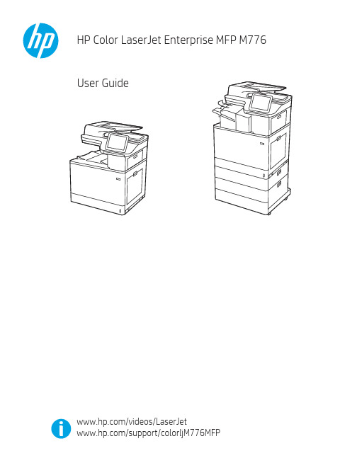
HP Color LaserJet Enterprise MFP M776用户指南说明书
Legal informationCopyright and License© Copyright 2019 HP Development Company, L.P.Reproduction, adaptation, or translation without prior written permission is prohibited, except as allowedunder the copyright laws.The information contained herein is subject to change without notice.The only warranties for HP products and services are set forth in the express warranty statementsaccompanying such products and services. Nothing herein should be construed as constituting anadditional warranty. HP shall not be liable for technical or editorial errors or omissions contained herein.Edition 1, 10/2019Trademark CreditsAdobe®, Adobe Photoshop®, Acrobat®, and PostScript® are trademarks of Adobe Systems Incorporated.Apple and the Apple logo are trademarks of Apple Inc., registered in the U.S. and other countries.macOS is a trademark of Apple Inc., registered in the U.S. and other countries.AirPrint is a trademark of Apple Inc., registered in the U.S. and other countries.Google™ is a trademark of Google Inc.Microsoft®, Windows®, Windows® XP, and Windows Vista® are U.S. registered trademarks of MicrosoftCorporation.UNIX® is a registered trademark of The Open Group.iiiT able of contents1 Printer overview (1)Warning icons (1)Potential shock hazard (2)Printer views (2)Printer front view (2)Printer back view (4)Interface ports (4)Control-panel view (5)How to use the touchscreen control panel (7)Printer specifications (8)T echnical specifications (8)Supported operating systems (11)Mobile printing solutions (12)Printer dimensions (13)Power consumption, electrical specifications, and acoustic emissions (15)Operating-environment range (15)Printer hardware setup and software installation (16)2 Paper trays (17)Introduction (17)Load paper to Tray 1 (multipurpose tray) (17)Load Tray 1 (multipurpose tray) (18)Tray 1 paper orientation (19)Use alternative letterhead mode (24)Enable Alternative Letterhead Mode by using the printer control-panel menus (24)Load paper to Tray 2 (24)Load Tray 2 (24)Tray 2 paper orientation (26)Use alternative letterhead mode (29)Enable Alternative Letterhead Mode by using the printer control-panel menus (29)Load paper to the 550-sheet paper tray (30)Load paper to the 550-sheet paper tray (30)550-sheet paper tray paper orientation (32)Use alternative letterhead mode (35)Enable Alternative Letterhead Mode by using the printer control-panel menus (35)ivLoad paper to the 2 x 550-sheet paper trays (36)Load paper to the 2 x 550-sheet paper trays (36)2 x 550-sheet paper tray paper orientation (38)Use alternative letterhead mode (41)Enable Alternative Letterhead Mode by using the printer control-panel menus (41)Load paper to the 2,700-sheet high-capacity input paper trays (41)Load paper to the 2,700-sheet high-capacity input paper trays (41)2,700-sheet HCI paper tray paper orientation (43)Use alternative letterhead mode (45)Enable Alternative Letterhead Mode by using the printer control-panel menus (45)Load and print envelopes (46)Print envelopes (46)Envelope orientation (46)Load and print labels (47)Manually feed labels (47)Label orientation (48)3 Supplies, accessories, and parts (49)Order supplies, accessories, and parts (49)Ordering (49)Supplies and accessories (50)Maintenance/long-life consumables (51)Customer self-repair parts (51)Dynamic security (52)Configure the HP toner-cartridge-protection supply settings (53)Introduction (53)Enable or disable the Cartridge Policy feature (53)Use the printer control panel to enable the Cartridge Policy feature (54)Use the printer control panel to disable the Cartridge Policy feature (54)Use the HP Embedded Web Server (EWS) to enable the Cartridge Policy feature (54)Use the HP Embedded Web Server (EWS) to disable the Cartridge Policy feature (55)Troubleshoot Cartridge Policy control panel error messages (55)Enable or disable the Cartridge Protection feature (55)Use the printer control panel to enable the Cartridge Protection feature (56)Use the printer control panel to disable the Cartridge Protection feature (56)Use the HP Embedded Web Server (EWS) to enable the Cartridge Protection feature (56)Use the HP Embedded Web Server (EWS) to disable the Cartridge Protection feature (57)Troubleshoot Cartridge Protection control panel error messages (57)Replace the toner cartridges (58)T oner-cartridge information (58)Remove and replace the cartridges (59)Replace the imaging drums (62)Imaging drum information (62)Remove and replace the imaging drums (63)Replace the toner-collection unit (66)T oner-collection unit information (66)vRemove and replace the toner-collection unit (67)Replace the staple cartridge (M776zs model only) (70)Staple cartridge information (70)Remove and replace the staple cartridge (71)4 Print (73)Print tasks (Windows) (73)How to print (Windows) (73)Automatically print on both sides (Windows) (74)Manually print on both sides (Windows) (74)Print multiple pages per sheet (Windows) (75)Select the paper type (Windows) (75)Additional print tasks (76)Print tasks (macOS) (77)How to print (macOS) (77)Automatically print on both sides (macOS) (77)Manually print on both sides (macOS) (77)Print multiple pages per sheet (macOS) (78)Select the paper type (macOS) (78)Additional print tasks (79)Store print jobs on the printer to print later or print privately (79)Introduction (79)Create a stored job (Windows) (79)Create a stored job (macOS) (80)Print a stored job (81)Delete a stored job (81)Delete a job that is stored on the printer (81)Change the job storage limit (82)Information sent to printer for Job Accounting purposes (82)Mobile printing (82)Introduction (82)Wi-Fi, Wi-Fi Direct Print, NFC, and BLE printing (82)Enable wireless printing (83)Change the Wi-Fi Direct name (83)HP ePrint via email (83)AirPrint (84)Android embedded printing (85)Print from a USB flash drive (85)Enable the USB port for printing (85)Method one: Enable the USB port from the printer control panel (85)Method two: Enable the USB port from the HP Embedded Web Server (network-connectedprinters only) (85)Print USB documents (86)Print using high-speed USB 2.0 port (wired) (86)Method one: Enable the high-speed USB 2.0 port from the printer control panel menus (86)Method two: Enable the high-speed USB 2.0 port from the HP Embedded Web Server (network-connected printers only) (87)vi5 Copy (88)Make a copy (88)Copy on both sides (duplex) (90)Additional copy tasks (92)6 Scan (93)Set up Scan to Email (93)Introduction (93)Before you begin (93)Step one: Access the HP Embedded Web Server (EWS) (94)Step two: Configure the Network Identification settings (95)Step three: Configure the Send to Email feature (96)Method one: Basic configuration using the Email Setup Wizard (96)Method two: Advanced configuration using the Email Setup (100)Step four: Configure the Quick Sets (optional) (104)Step five: Set up Send to Email to use Office 365 Outlook (optional) (105)Introduction (105)Configure the outgoing email server (SMTP) to send an email from an Office 365 Outlookaccount (105)Set up Scan to Network Folder (108)Introduction (108)Before you begin (108)Step one: Access the HP Embedded Web Server (EWS) (108)Step two: Set up Scan to Network Folder (109)Method one: Use the Scan to Network Folder Wizard (109)Method two: Use Scan to Network Folder Setup (110)Step one: Begin the configuration (110)Step two: Configure the Scan to Network Folder settings (111)Step three: Complete the configuration (118)Set up Scan to SharePoint (118)Introduction (118)Before you begin (118)Step one: Access the HP Embedded Web Server (EWS) (118)Step two: Enable Scan to SharePoint and create a Scan to SharePoint Quick Set (119)Scan a file directly to a SharePoint site (121)Quick Set scan settings and options for Scan to SharePoint (122)Set up Scan to USB Drive (123)Introduction (124)Step one: Access the HP Embedded Web Server (EWS) (124)Step two: Enable Scan to USB Drive (124)Step three: Configure the Quick Sets (optional) (125)Default scan settings for Scan to USB Drive setup (126)Default file settings for Save to USB setup (126)Scan to email (127)Introduction (127)Scan to email (127)Scan to job storage (129)viiIntroduction (129)Scan to job storage on the printer (130)Print from job storage on the printer (132)Scan to network folder (132)Introduction (132)Scan to network folder (132)Scan to SharePoint (134)Introduction (134)Scan to SharePoint (134)Scan to USB drive (136)Introduction (136)Scan to USB drive (136)Use HP JetAdvantage business solutions (138)Additional scan tasks (138)7 Fax (140)Set up fax (140)Introduction (140)Set up fax by using the printer control panel (140)Change fax configurations (141)Fax dialing settings (141)General fax send settings (142)Fax receive settings (143)Send a fax (144)Additional fax tasks (146)8 Manage the printer (147)Advanced configuration with the HP Embedded Web Server (EWS) (147)Introduction (147)How to access the HP Embedded Web Server (EWS) (148)HP Embedded Web Server features (149)Information tab (149)General tab (149)Copy/Print tab (150)Scan/Digital Send tab (151)Fax tab (152)Supplies tab (153)Troubleshooting tab (153)Security tab (153)HP Web Services tab (154)Networking tab (154)Other Links list (156)Configure IP network settings (157)Printer sharing disclaimer (157)View or change network settings (157)Rename the printer on a network (157)viiiManually configure IPv4 TCP/IP parameters from the control panel (158)Manually configure IPv6 TCP/IP parameters from the control panel (158)Link speed and duplex settings (159)Printer security features (160)Introduction (160)Security statements (160)Assign an administrator password (160)Use the HP Embedded Web Server (EWS) to set the password (160)Provide user access credentials at the printer control panel (161)IP Security (161)Encryption support: HP High Performance Secure Hard Disks (161)Lock the formatter (161)Energy-conservation settings (161)Set the sleep timer and configure the printer to use 1 watt or less of power (161)Set the sleep schedule (162)Set the idle settings (162)HP Web Jetadmin (163)Software and firmware updates (163)9 Solve problems (164)Customer support (164)Control panel help system (165)Reset factory settings (165)Introduction (165)Method one: Reset factory settings from the printer control panel (165)Method two: Reset factory settings from the HP Embedded Web Server (network-connectedprinters only) (166)A “Cartridge is low” or “Cartridge is very low” message displays on the printer control panel (166)Change the “Very Low” settings (166)Change the “Very Low” settings at the control panel (166)For printers with fax capability (167)Order supplies (167)Printer does not pick up paper or misfeeds (167)Introduction (167)The printer does not pick up paper (167)The printer picks up multiple sheets of paper (171)The document feeder jams, skews, or picks up multiple sheets of paper (174)Clear paper jams (174)Introduction (174)Paper jam locations (174)Auto-navigation for clearing paper jams (175)Experiencing frequent or recurring paper jams? (175)Clear paper jams in the document feeder - 31.13.yz (176)Clear paper jams in Tray 1 (13.A1) (177)Clear paper jams in Tray 2 (13.A2) (182)Clear paper jams in the fuser (13.B9, 13.B2, 13.FF) (188)ixClear paper jams in the duplex area (13.D3) (194)Clear paper jams in the 550-sheet trays (13.A3, 13.A4) (199)Clear paper jams in the 2 x 550 paper trays (13.A4, 13.A5) (206)Clear paper jams in the 2,700-sheet high-capacity input paper trays (13.A3, 13.A4, 13.A5, 13.A7) (213)Resolving color print quality problems (220)Introduction (220)Troubleshoot print quality (221)Update the printer firmware (221)Print from a different software program (221)Check the paper-type setting for the print job (221)Check the paper type setting on the printer (221)Check the paper type setting (Windows) (221)Check the paper type setting (macOS) (222)Check toner-cartridge status (222)Step one: Print the Supplies Status Page (222)Step two: Check supplies status (222)Print a cleaning page (222)Visually inspect the toner cartridge or cartridges (223)Check paper and the printing environment (223)Step one: Use paper that meets HP specifications (223)Step two: Check the environment (223)Step three: Set the individual tray alignment (224)Try a different print driver (224)Troubleshoot color quality (225)Calibrate the printer to align the colors (225)Troubleshoot image defects (225)Improve copy image quality (233)Check the scanner glass for dirt and smudges (233)Calibrate the scanner (234)Check the paper settings (235)Check the paper selection options (235)Check the image-adjustment settings (235)Optimize copy quality for text or pictures (236)Edge-to-edge copying (236)Improve scan image quality (236)Check the scanner glass for dirt and smudges (237)Check the resolution settings (238)Check the color settings (238)Check the image-adjustment settings (239)Optimize scan quality for text or pictures (239)Check the output-quality settings (240)Improve fax image quality (240)Check the scanner glass for dirt and smudges (240)Check the send-fax resolution settings (242)Check the image-adjustment settings (242)Optimize fax quality for text or pictures (242)Check the error-correction setting (243)xSend to a different fax machine (243)Check the sender's fax machine (243)Solve wired network problems (244)Introduction (244)Poor physical connection (244)The computer is unable to communicate with the printer (244)The printer is using incorrect link and duplex settings for the network (245)New software programs might be causing compatibility problems (245)The computer or workstation might be set up incorrectly (245)The printer is disabled, or other network settings are incorrect (245)Solve wireless network problems (245)Introduction (245)Wireless connectivity checklist (245)The printer does not print after the wireless configuration completes (246)The printer does not print, and the computer has a third-party firewall installed (246)The wireless connection does not work after moving the wireless router or printer (247)Cannot connect more computers to the wireless printer (247)The wireless printer loses communication when connected to a VPN (247)The network does not appear in the wireless networks list (247)The wireless network is not functioning (247)Reduce interference on a wireless network (248)Solve fax problems (248)Checklist for solving fax problems (248)What type of phone line are you using? (249)Are you using a surge-protection device? (249)Are you using a phone company voice-messaging service or an answering machine? (249)Does your phone line have a call-waiting feature? (249)Check fax accessory status (249)General fax problems (250)The fax failed to send (250)No fax address book button displays (250)Not able to locate the Fax settings in HP Web Jetadmin (250)The header is appended to the top of the page when the overlay option is enabled (251)A mix of names and numbers is in the recipients box (251)A one-page fax prints as two pages (251)A document stops in the document feeder in the middle of faxing (251)The volume for sounds coming from the fax accessory is too high or too low (251)Index (252)xiPrinter overview1Review the location of features on the printer, the physical and technical specifications of the printer,and where to locate setup information.For video assistance, see /videos/LaserJet.The following information is correct at the time of publication. For current information, see /support/colorljM776MFP.For more information:HP's all-inclusive help for the printer includes the following information:●Install and configure●Learn and use●Solve problems●Download software and firmware updates●Join support forums●Find warranty and regulatory informationWarning iconsUse caution if you see a warning icon on your HP printer, as indicated in the icon definitions.●Caution: Electric shock●Caution: Hot surface●Caution: Keep body parts away from moving partsPrinter overview1●Caution: Sharp edge in close proximity●WarningPotential shock hazardReview this important safety information.●Read and understand these safety statements to avoid an electrical shock hazard.●Always follow basic safety precautions when using this product to reduce risk of injury from fire orelectric shock.●Read and understand all instructions in the user guide.●Observe all warnings and instructions marked on the product.●Use only a grounded electrical outlet when connecting the product to a power source. If you do notknow whether the outlet is grounded, check with a qualified electrician.●Do not touch the contacts on any of the sockets on the product. Replace damaged cordsimmediately.●Unplug this product from wall outlets before cleaning.●Do not install or use this product near water or when you are wet.●Install the product securely on a stable surface.●Install the product in a protected location where no one can step on or trip over the power cord.Printer viewsIdentify certain parts of the printer and the control panel.Printer front viewLocate features on the front of the printer.2Chapter 1 Printer overviewPrinter front view3Printer back viewLocate features on the back of the printer.Interface portsLocate the interface ports on the printer formatter. 4Chapter 1 Printer overviewControl-panel viewThe control panel provides access to the printer features and indicates the current status of the printer.NOTE:Tilt the control panel for easier viewing.The Home screen provides access to the printer features and indicates the current status of the printer.screens.NOTE:The features that appear on the Home screen can vary, depending on the printerconfiguration.Control-panel view5Figure 1-1Control-panel view?i 12:42 PM6Chapter 1 Printer overviewHow to use the touchscreen control panelPerform the following actions to use the printer touchscreen control panel.T ouchT ouch an item on the screen to select that item or open that menu. Also, when scrolling T ouch the Settings icon to open the Settings app.How to use the touchscreen control panel 7SwipeT ouch the screen and then move your finger horizontally to scroll the screen sideways.Swipe until the Settings app displays.Printer specificationsDetermine the specifications for your printer model.IMPORTANT:The following specifications are correct at the time of publication, but they are subject to change. For current information, see /support/colorljM776MFP .T echnical specificationsReview the printer technical specifications.Product numbers for each model ●M776dn - #T3U55A ●Flow M776z - #3WT91A ●Flow M776zs - #T3U56APaper handling specificationsPaper handling features Tray 1 (100-sheet capacity)Included Included Included Tray 2 (550-sheet capacity)IncludedIncludedIncluded8Chapter 1 Printer overview550-sheet paper trayOptional Included Not included NOTE:The M776dn models accept one optional550-sheet tray.Optional Included Included2 x 550-sheet paper tray and standNOTE:The M776dn models accept one optional550-sheet tray that may be installed on top of thestand.Optional Not included Not included2,700-sheet high-capacity input (HCI) paper trayand standNOTE:The M776dn models accept one optional550-sheet tray that may be installed on top of theoptional printer stand.Printer standOptional Not included Not included NOTE:The M776dn models accept one optional550-sheet tray that may be installed on top of theoptional printer stand.Inner finisher accessory Not included Not included Included Automatic duplex printing Included IncludedIncludedIncluded Included Included10/100/1000 Ethernet LAN connection with IPv4and IPv6Hi-Speed USB 2.0Included Included IncludedIncluded Included IncludedEasy-access USB port for printing from a USBflash drive or upgrading the firmwareIncluded Included Included Hardware Integration Pocket for connectingaccessory and third-party devicesHP Internal USB Ports Optional Optional OptionalOptional Optional OptionalHP Jetdirect 2900nw Print Server accessory forWi-Fi connectivity and an additional Ethernet portOptional IncludedIncludedHP Jetdirect 3100w accessory for Wi-Fi, BLE, NFC,and proximity badge readingPrints 45 pages per minute (ppm) on Letter-sizepaper and 46 ppm on A4-size paperEasy-access USB printing for printing from a USBIncluded Included Includedflash driveT echnical specifications9Included Included Included Store jobs in the printer memory to print later orprint privatelyScans 100 pages per minute (ppm) on A4 andIncluded Included Included letter-size paper one-sidedIncluded Included Included 200-page document feeder with dual-headscanning for single-pass duplex copying andscanningNot included Included Included HP EveryPage T echnologies including ultrasonicmulti-feed detectionNot included Included Included Embedded optical character recognition (OCR)provides the ability to convert printed pages intotext that can be edited or searched using acomputerIncluded Included Included SMART Label feature provides paper-edgedetection for automatic page croppingIncluded Included Included Automatic page orientation for pages that haveat least 100 characters of textIncluded Automatic tone adjustment sets contrast,Included Includedbrightness, and background removal for eachpageIncluded Included Includedfolders on a networkIncludedSend documents to SharePoint®Included IncludedIncluded Included Included NOTE:Memory reported on the configurationpage will change from 2.5 GB to 3 GB with theoptional 1 GB SODIMM installed.Mass storage: 500 GB hard disk drive Included Included IncludedSecurity: HP Trusted Platform Module (TPM)Included Included IncludedT ouchscreen control panel Included Included IncludedRetractable keyboard Not included Included Included 10Chapter 1 Printer overviewFax Optional Included IncludedSupported operating systemsUse the following information to ensure printer compatibility with your computer operating system.Linux: For information and print drivers for Linux, go to /go/linuxprinting.UNIX: For information and print drivers for UNIX®, go to /go/unixmodelscripts.The following information applies to the printer-specific Windows HP PCL 6 print drivers, HP print driversfor macOS, and to the software installer.Windows: Download HP Easy Start from /LaserJet to install the HP print driver. Or, go tothe printer-support website for this printer: /support/colorljM776MFP to download the printdriver or the software installer to install the HP print driver.macOS: Mac computers are supported with this printer. Download HP Easy Start either from /LaserJet or from the Printer Support page, and then use HP Easy Start to install the HP print driver.1.Go to /LaserJet.2.Follow the steps provided to download the printer software.Windows 7, 32-bit and 64-bit The “HP PCL 6” printer-specific print driver is installed for this operating system aspart of the software installation.Windows 8.1, 32-bit and 64-bit The “HP PCL-6” V4 printer-specific print driver is installed for this operating systemas part of the software installation.Windows 10, 32-bit and 64-bit The “HP PCL-6” V4 printer-specific print driver is installed for this operating systemas part of the software installation.Windows Server 2008 R2, SP 1, 64-bit The PCL 6 printer-specific print driver is available for download from the printer-support website. Download the driver, and then use the Microsoft Add Printer tool toinstall it.Windows Server 2012, 64-bit The PCL 6 printer-specific print driver is available for download from the printer-support website. Download the driver, and then use the Microsoft Add Printer tool toinstall it.Windows Server 2012 R2, 64-bit The PCL 6 printer-specific print driver is available for download from the printer-support website. Download the driver, and then use the Microsoft Add Printer tool toinstall it.Windows Server 2016, 64-bit The PCL 6 printer-specific print driver is available for download from the printer-support website. Download the driver, and then use the Microsoft Add Printer tool toinstall it.Windows Server 2019, 64-bit The PCL 6 printer-specific print driver is available for download from the printer-support website. Download the driver, and then use the Microsoft Add Printer tool toinstall it.Supported operating systems11macOS 10.13 High Sierra, macOS 10.14 MojaveDownload HP Easy Start from /LaserJet , and then use it to install the print driver.NOTE:Supported operating systems can change.NOTE:For a current list of supported operating systems and HP’s all-inclusive help for the printer, go to /support/colorljM776MFP .NOTE:For details on client and server operating systems and for HP UPD driver support for this printer, go to /go/upd . Under Additional information , click Specifications .●Internet connection●Dedicated USB 1.1 or 2.0 connection or a network connection● 2 GB of available hard-disk space ●1 GB RAM (32-bit) or2 GB RAM (64-bit)●Internet connection●Dedicated USB 1.1 or 2.0 connection or a network connection●1.5 GB of available hard-disk spaceNOTE:The Windows software installer installs the HP Smart Device Agent Base service. The file size is less than 100 kb. Its only function is to check for printers connected via USB hourly. No data is collected. If a USB printer is found, it then tries to locate a JetAdvantage Management Connector (JAMc) instance on the network. If a JAMc is found, the HP Smart Device Agent Base is securelyupgraded to a full Smart Device Agent from JAMc, which will then allow printed pages to be accounted for in a Managed Print Services (MPS) account. The driver-only web packs downloaded from for the printer and installed through the Add Printer wizard do not install this service.T o uninstall the service, open the Control Panel , select Programs or Programs and Features , and then select Add/Remove Programs or Uninstall a Programto remove the service. The file name isHPSmartDeviceAgentBase.Mobile printing solutionsHP offers multiple mobile printing solutions to enable easy printing to an HP printer from a laptop, tablet, smartphone, or other mobile device.T o see the full list and to determine the best choice, go to /go/MobilePrinting .NOTE:Update the printer firmware to ensure all mobile printing capabilities are supported.●Wi-Fi Direct (wireless models only, with HP Jetdirect 3100w BLE/NFC/Wireless accessory installed)●HP ePrint via email (Requires HP Web Services to be enabled and the printer to be registered with HP Connected)●HP Smart app ●Google Cloud Print12Chapter 1 Printer overview。
惠普彩色激光打印机 Pro M454 和惠普彩色激光多功能一体机 Pro M479 维修手册说明书
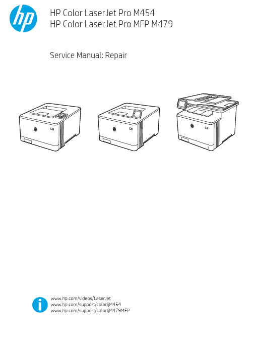
Table -1 Revision history Revision number 1
Revision date 6/2019
Revision notes HP LaserJet Pro M454 HP LaserJet Pro MFP M479 Repair manual initial release
Additional service and support for HP internal personnel HP internal personnel, go to one of the following Web-based Interactive Search Engine (WISE) sites: Americas (AMS) – https:///wise/home/ams-enWISE - English – https:///wise/home/ams-esWISE - Spanish – https:///wise/home/ams-ptWISE - Portuguese – https:///wise/home/ams-frWISE - French Asia Pacific / Japan (APJ) ○ https:///wise/home/apj-enWISE - English ○ https:///wise/home/apj-jaWISE - Japanese ○ https:///wise/home/apj-koWISE - Korean ○ https:///wise/home/apj-zh-HansWISE - Chinese (simplified)
Find information about the following topics ● Service manuals ● Service advisories ● Up-to-date control panel message (CPMD) troubleshooting ● Install and configure ● Printer specifications ● Solutions for printer issues and emerging issues ● Remove and replace part instructions and videos ● Warranty and regulatory information
Synopsys OptoDesigner 2020.09安装指南说明书
3. Troubleshooting scanning issues........................................................25
Accidental full scan proliferation by folder paths which include build or commit ID............................ 25 Solution......................................................................................................................................25
Contents
Contents
Preface....................................................................................................5
1. Scanning best practices......................................................................... 8
无损检测技术中常用的数据处理与分析软件推荐

无损检测技术中常用的数据处理与分析软件推荐无损检测技术是一种重要的工程检测方法,广泛应用于工业生产和科学研究领域。
在无损检测过程中,数据处理与分析软件是不可或缺的工具,它可以帮助工程师对采集到的数据进行处理、分析和解释,提高检测效率和准确性。
下面将介绍一些常用的数据处理与分析软件。
一、MATLABMATLAB是一种强大的科学计算软件,它在无损检测技术领域也有广泛应用。
MATLAB提供了丰富的数据处理和分析函数,可以处理各种数据类型,包括图像、声音和振动等。
用户可以通过编写脚本和函数来实现针对性的数据处理算法。
此外,MATLAB还提供了交互式的用户界面,方便用户进行数据可视化和结果展示。
二、LabVIEWLabVIEW是一种图形化编程环境,适用于无损检测数据的实时处理和分析。
LabVIEW以可视化的方式展示程序结构和算法,使得用户可以直观地构建数据处理的流程图。
LabVIEW还提供了丰富的信号处理函数和工具箱,包括滤波、峰值检测、频谱分析等。
用户可以通过拖拽模块和线连接来搭建数据处理的流程,简化了程序的编写和调试过程。
三、OriginProOriginPro是一种统计分析与数据可视化软件,也常用于无损检测技术中的数据处理和分析。
OriginPro提供了丰富的统计分析函数和图表绘制工具,可以对大量数据进行分析和可视化展示。
用户可以通过直观的操作界面,进行数据清洗、处理和分析,得出结论和决策。
OriginPro还支持自定义函数和脚本,适用于复杂的数据处理需求。
四、Python + NumPy/SciPy/MatplotlibPython是一种通用的编程语言,在科学计算和数据处理领域也有广泛应用。
与其他软件相比,Python具有开源、便捷和强大的特点。
NumPy是Python的一个科学计算库,提供了高效的数组操作和线性代数函数;SciPy是一个科学计算库,提供了统计分析、优化和插值等函数;Matplotlib是一个绘图库,可以绘制高质量的二维和三维图表。
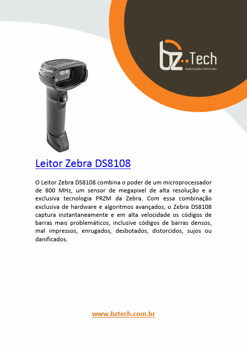
斑马技术公司DS8108数字扫描仪产品参考指南说明书
纹理物体缺陷的视觉检测算法研究--优秀毕业论文
摘 要
在竞争激烈的工业自动化生产过程中,机器视觉对产品质量的把关起着举足 轻重的作用,机器视觉在缺陷检测技术方面的应用也逐渐普遍起来。与常规的检 测技术相比,自动化的视觉检测系统更加经济、快捷、高效与 安全。纹理物体在 工业生产中广泛存在,像用于半导体装配和封装底板和发光二极管,现代 化电子 系统中的印制电路板,以及纺织行业中的布匹和织物等都可认为是含有纹理特征 的物体。本论文主要致力于纹理物体的缺陷检测技术研究,为纹理物体的自动化 检测提供高效而可靠的检测算法。 纹理是描述图像内容的重要特征,纹理分析也已经被成功的应用与纹理分割 和纹理分类当中。本研究提出了一种基于纹理分析技术和参考比较方式的缺陷检 测算法。这种算法能容忍物体变形引起的图像配准误差,对纹理的影响也具有鲁 棒性。本算法旨在为检测出的缺陷区域提供丰富而重要的物理意义,如缺陷区域 的大小、形状、亮度对比度及空间分布等。同时,在参考图像可行的情况下,本 算法可用于同质纹理物体和非同质纹理物体的检测,对非纹理物体 的检测也可取 得不错的效果。 在整个检测过程中,我们采用了可调控金字塔的纹理分析和重构技术。与传 统的小波纹理分析技术不同,我们在小波域中加入处理物体变形和纹理影响的容 忍度控制算法,来实现容忍物体变形和对纹理影响鲁棒的目的。最后可调控金字 塔的重构保证了缺陷区域物理意义恢复的准确性。实验阶段,我们检测了一系列 具有实际应用价值的图像。实验结果表明 本文提出的纹理物体缺陷检测算法具有 高效性和易于实现性。 关键字: 缺陷检测;纹理;物体变形;可调控金字塔;重构
Keywords: defect detection, texture, object distortion, steerable pyramid, reconstruction
II
jstd035声学扫描
JOINT INDUSTRY STANDARDAcoustic Microscopy for Non-HermeticEncapsulatedElectronicComponents IPC/JEDEC J-STD-035APRIL1999Supersedes IPC-SM-786 Supersedes IPC-TM-650,2.6.22Notice EIA/JEDEC and IPC Standards and Publications are designed to serve thepublic interest through eliminating misunderstandings between manufacturersand purchasers,facilitating interchangeability and improvement of products,and assisting the purchaser in selecting and obtaining with minimum delaythe proper product for his particular need.Existence of such Standards andPublications shall not in any respect preclude any member or nonmember ofEIA/JEDEC or IPC from manufacturing or selling products not conformingto such Standards and Publications,nor shall the existence of such Standardsand Publications preclude their voluntary use by those other than EIA/JEDECand IPC members,whether the standard is to be used either domestically orinternationally.Recommended Standards and Publications are adopted by EIA/JEDEC andIPC without regard to whether their adoption may involve patents on articles,materials,or processes.By such action,EIA/JEDEC and IPC do not assumeany liability to any patent owner,nor do they assume any obligation whateverto parties adopting the Recommended Standard or ers are alsowholly responsible for protecting themselves against all claims of liabilities forpatent infringement.The material in this joint standard was developed by the EIA/JEDEC JC-14.1Committee on Reliability Test Methods for Packaged Devices and the IPCPlastic Chip Carrier Cracking Task Group(B-10a)The J-STD-035supersedes IPC-TM-650,Test Method2.6.22.For Technical Information Contact:Electronic Industries Alliance/ JEDEC(Joint Electron Device Engineering Council)2500Wilson Boulevard Arlington,V A22201Phone(703)907-7560Fax(703)907-7501IPC2215Sanders Road Northbrook,IL60062-6135 Phone(847)509-9700Fax(847)509-9798Please use the Standard Improvement Form shown at the end of thisdocument.©Copyright1999.The Electronic Industries Alliance,Arlington,Virginia,and IPC,Northbrook,Illinois.All rights reserved under both international and Pan-American copyright conventions.Any copying,scanning or other reproduction of these materials without the prior written consent of the copyright holder is strictly prohibited and constitutes infringement under the Copyright Law of the United States.IPC/JEDEC J-STD-035Acoustic Microscopyfor Non-Hermetic EncapsulatedElectronicComponentsA joint standard developed by the EIA/JEDEC JC-14.1Committee on Reliability Test Methods for Packaged Devices and the B-10a Plastic Chip Carrier Cracking Task Group of IPCUsers of this standard are encouraged to participate in the development of future revisions.Contact:EIA/JEDEC Engineering Department 2500Wilson Boulevard Arlington,V A22201 Phone(703)907-7500 Fax(703)907-7501IPC2215Sanders Road Northbrook,IL60062-6135 Phone(847)509-9700Fax(847)509-9798ASSOCIATION CONNECTINGELECTRONICS INDUSTRIESAcknowledgmentMembers of the Joint IPC-EIA/JEDEC Moisture Classification Task Group have worked to develop this document.We would like to thank them for their dedication to this effort.Any Standard involving a complex technology draws material from a vast number of sources.While the principal members of the Joint Moisture Classification Working Group are shown below,it is not possible to include all of those who assisted in the evolution of this Standard.To each of them,the mem-bers of the EIA/JEDEC and IPC extend their gratitude.IPC Packaged Electronic Components Committee ChairmanMartin FreedmanAMP,Inc.IPC Plastic Chip Carrier Cracking Task Group,B-10a ChairmanSteven MartellSonoscan,Inc.EIA/JEDEC JC14.1CommitteeChairmanJack McCullenIntel Corp.EIA/JEDEC JC14ChairmanNick LycoudesMotorolaJoint Working Group MembersCharlie Baker,TIChristopher Brigham,Hi/FnRalph Carbone,Hewlett Packard Co. Don Denton,TIMatt Dotty,AmkorMichele J.DiFranza,The Mitre Corp. Leo Feinstein,Allegro Microsystems Inc.Barry Fernelius,Hewlett Packard Co. Chris Fortunko,National Institute of StandardsRobert J.Gregory,CAE Electronics, Inc.Curtis Grosskopf,IBM Corp.Bill Guthrie,IBM Corp.Phil Johnson,Philips Semiconductors Nick Lycoudes,MotorolaSteven R.Martell,Sonoscan Inc. Jack McCullen,Intel Corp.Tom Moore,TIDavid Nicol,Lucent Technologies Inc.Pramod Patel,Advanced Micro Devices Inc.Ramon R.Reglos,XilinxCorazon Reglos,AdaptecGerald Servais,Delphi Delco Electronics SystemsRichard Shook,Lucent Technologies Inc.E.Lon Smith,Lucent Technologies Inc.Randy Walberg,NationalSemiconductor Corp.Charlie Wu,AdaptecEdward Masami Aoki,HewlettPackard LaboratoriesFonda B.Wu,Raytheon Systems Co.Richard W.Boerdner,EJE ResearchVictor J.Brzozowski,NorthropGrumman ES&SDMacushla Chen,Wus Printed CircuitCo.Ltd.Jeffrey C.Colish,Northrop GrummanCorp.Samuel J.Croce,Litton AeroProducts DivisionDerek D-Andrade,Surface MountTechnology CentreRao B.Dayaneni,Hewlett PackardLaboratoriesRodney Dehne,OEM WorldwideJames F.Maguire,Boeing Defense&Space GroupKim Finch,Boeing Defense&SpaceGroupAlelie Funcell,Xilinx Inc.Constantino J.Gonzalez,ACMEMunir Haq,Advanced Micro DevicesInc.Larry A.Hargreaves,DC.ScientificInc.John T.Hoback,Amoco ChemicalCo.Terence Kern,Axiom Electronics Inc.Connie M.Korth,K-Byte/HibbingManufacturingGabriele Marcantonio,NORTELCharles Martin,Hewlett PackardLaboratoriesRichard W.Max,Alcatel NetworkSystems Inc.Patrick McCluskey,University ofMarylandJames H.Moffitt,Moffitt ConsultingServicesRobert Mulligan,Motorola Inc.James E.Mumby,CibaJohn Northrup,Lockheed MartinCorp.Dominique K.Numakura,LitchfieldPrecision ComponentsNitin B.Parekh,Unisys Corp.Bella Poborets,Lucent TechnologiesInc.D.Elaine Pope,Intel Corp.Ray Prasad,Ray Prasad ConsultancyGroupAlbert Puah,Adaptec Inc.William Sepp,Technic Inc.Ralph W.Taylor,Lockheed MartinCorp.Ed R.Tidwell,DSC CommunicationsCorp.Nick Virmani,Naval Research LabKen Warren,Corlund ElectronicsCorp.Yulia B.Zaks,Lucent TechnologiesInc.IPC/JEDEC J-STD-035April1999 iiTable of Contents1SCOPE (1)2DEFINITIONS (1)2.1A-mode (1)2.2B-mode (1)2.3Back-Side Substrate View Area (1)2.4C-mode (1)2.5Through Transmission Mode (2)2.6Die Attach View Area (2)2.7Die Surface View Area (2)2.8Focal Length(FL) (2)2.9Focus Plane (2)2.10Leadframe(L/F)View Area (2)2.11Reflective Acoustic Microscope (2)2.12Through Transmission Acoustic Microscope (2)2.13Time-of-Flight(TOF) (3)2.14Top-Side Die Attach Substrate View Area (3)3APPARATUS (3)3.1Reflective Acoustic Microscope System (3)3.2Through Transmission AcousticMicroscope System (4)4PROCEDURE (4)4.1Equipment Setup (4)4.2Perform Acoustic Scans..........................................4Appendix A Acoustic Microscopy Defect CheckSheet (6)Appendix B Potential Image Pitfalls (9)Appendix C Some Limitations of AcousticMicroscopy (10)Appendix D Reference Procedure for PresentingApplicable Scanned Data (11)FiguresFigure1Example of A-mode Display (1)Figure2Example of B-mode Display (1)Figure3Example of C-mode Display (2)Figure4Example of Through Transmission Display (2)Figure5Diagram of a Reflective Acoustic MicroscopeSystem (3)Figure6Diagram of a Through Transmission AcousticMicroscope System (3)April1999IPC/JEDEC J-STD-035iiiIPC/JEDEC J-STD-035April1999This Page Intentionally Left BlankivApril1999IPC/JEDEC J-STD-035 Acoustic Microscopy for Non-Hermetic EncapsulatedElectronic Components1SCOPEThis test method defines the procedures for performing acoustic microscopy on non-hermetic encapsulated electronic com-ponents.This method provides users with an acoustic microscopy processflow for detecting defects non-destructively in plastic packages while achieving reproducibility.2DEFINITIONS2.1A-mode Acoustic data collected at the smallest X-Y-Z region defined by the limitations of the given acoustic micro-scope.An A-mode display contains amplitude and phase/polarity information as a function of time offlight at a single point in the X-Y plane.See Figure1-Example of A-mode Display.IPC-035-1 Figure1Example of A-mode Display2.2B-mode Acoustic data collected along an X-Z or Y-Z plane versus depth using a reflective acoustic microscope.A B-mode scan contains amplitude and phase/polarity information as a function of time offlight at each point along the scan line.A B-mode scan furnishes a two-dimensional(cross-sectional)description along a scan line(X or Y).See Figure2-Example of B-mode Display.IPC-035-2 Figure2Example of B-mode Display(bottom half of picture on left)2.3Back-Side Substrate View Area(Refer to Appendix A,Type IV)The interface between the encapsulant and the back of the substrate within the outer edges of the substrate surface.2.4C-mode Acoustic data collected in an X-Y plane at depth(Z)using a reflective acoustic microscope.A C-mode scan contains amplitude and phase/polarity information at each point in the scan plane.A C-mode scan furnishes a two-dimensional(area)image of echoes arising from reflections at a particular depth(Z).See Figure3-Example of C-mode Display.1IPC/JEDEC J-STD-035April1999IPC-035-3 Figure3Example of C-mode Display2.5Through Transmission Mode Acoustic data collected in an X-Y plane throughout the depth(Z)using a through trans-mission acoustic microscope.A Through Transmission mode scan contains only amplitude information at each point in the scan plane.A Through Transmission scan furnishes a two-dimensional(area)image of transmitted ultrasound through the complete thickness/depth(Z)of the sample/component.See Figure4-Example of Through Transmission Display.IPC-035-4 Figure4Example of Through Transmission Display2.6Die Attach View Area(Refer to Appendix A,Type II)The interface between the die and the die attach adhesive and/or the die attach adhesive and the die attach substrate.2.7Die Surface View Area(Refer to Appendix A,Type I)The interface between the encapsulant and the active side of the die.2.8Focal Length(FL)The distance in water at which a transducer’s spot size is at a minimum.2.9Focus Plane The X-Y plane at a depth(Z),which the amplitude of the acoustic signal is maximized.2.10Leadframe(L/F)View Area(Refer to Appendix A,Type V)The imaged area which extends from the outer L/F edges of the package to the L/F‘‘tips’’(wedge bond/stitch bond region of the innermost portion of the L/F.)2.11Reflective Acoustic Microscope An acoustic microscope that uses one transducer as both the pulser and receiver. (This is also known as a pulse/echo system.)See Figure5-Diagram of a Reflective Acoustic Microscope System.2.12Through Transmission Acoustic Microscope An acoustic microscope that transmits ultrasound completely through the sample from a sending transducer to a receiver on the opposite side.See Figure6-Diagram of a Through Transmis-sion Acoustic Microscope System.2April1999IPC/JEDEC J-STD-0353IPC/JEDEC J-STD-035April1999 3.1.6A broad band acoustic transducer with a center frequency in the range of10to200MHz for subsurface imaging.3.2Through Transmission Acoustic Microscope System(see Figure6)comprised of:3.2.1Items3.1.1to3.1.6above3.2.2Ultrasonic pulser(can be a pulser/receiver as in3.1.1)3.2.3Separate receiving transducer or ultrasonic detection system3.3Reference packages or standards,including packages with delamination and packages without delamination,for use during equipment setup.3.4Sample holder for pre-positioning samples.The holder should keep the samples from moving during the scan and maintain planarity.4PROCEDUREThis procedure is generic to all acoustic microscopes.For operational details related to this procedure that apply to a spe-cific model of acoustic microscope,consult the manufacturer’s operational manual.4.1Equipment Setup4.1.1Select the transducer with the highest useable ultrasonic frequency,subject to the limitations imposed by the media thickness and acoustic characteristics,package configuration,and transducer availability,to analyze the interfaces of inter-est.The transducer selected should have a low enough frequency to provide a clear signal from the interface of interest.The transducer should have a high enough frequency to delineate the interface of interest.Note:Through transmission mode may require a lower frequency and/or longer focal length than reflective mode.Through transmission is effective for the initial inspection of components to determine if defects are present.4.1.2Verify setup with the reference packages or standards(see3.3above)and settings that are appropriate for the trans-ducer chosen in4.1.1to ensure that the critical parameters at the interface of interest correlate to the reference standard uti-lized.4.1.3Place units in the sample holder in the coupling medium such that the upper surface of each unit is parallel with the scanning plane of the acoustic transducer.Sweep air bubbles away from the unit surface and from the bottom of the trans-ducer head.4.1.4At afixed distance(Z),align the transducer and/or stage for the maximum reflected amplitude from the top surface of the sample.The transducer must be perpendicular to the sample surface.4.1.5Focus by maximizing the amplitude,in the A-mode display,of the reflection from the interface designated for imag-ing.This is done by adjusting the Z-axis distance between the transducer and the sample.4.2Perform Acoustic Scans4.2.1Inspect the acoustic image(s)for any anomalies,verify that the anomaly is a package defect or an artifact of the imaging process,and record the results.(See Appendix A for an example of a check sheet that may be used.)To determine if an anomaly is a package defect or an artifact of the imaging process it is recommended to analyze the A-mode display at the location of the anomaly.4.2.2Consider potential pitfalls in image interpretation listed in,but not limited to,Appendix B and some of the limita-tions of acoustic microscopy listed in,but not limited to,Appendix C.If necessary,make adjustments to the equipment setup to optimize the results and rescan.4April1999IPC/JEDEC J-STD-035 4.2.3Evaluate the acoustic images using the failure criteria specified in other appropriate documents,such as J-STD-020.4.2.4Record the images and thefinal instrument setup parameters for documentation purposes.An example checklist is shown in Appendix D.5IPC/JEDEC J-STD-035April19996April1999IPC/JEDEC J-STD-035Appendix AAcoustic Microscopy Defect Check Sheet(continued)CIRCUIT SIDE SCANImage File Name/PathDelamination(Type I)Die Circuit Surface/Encapsulant Number Affected:Average%Location:Corner Edge Center (Type II)Die/Die Attach Number Affected:Average%Location:Corner Edge Center (Type III)Encapsulant/Substrate Number Affected:Average%Location:Corner Edge Center (Type V)Interconnect tip Number Affected:Average%Interconnect Number Affected:Max.%Length(Type VI)Intra-Laminate Number Affected:Average%Location:Corner Edge Center Comments:CracksAre cracks present:Yes NoIf yes:Do any cracks intersect:bond wire ball bond wedge bond tab bump tab leadDoes crack extend from leadfinger to any other internal feature:Yes NoDoes crack extend more than two-thirds the distance from any internal feature to the external surfaceof the package:Yes NoAdditional verification required:Yes NoComments:Mold Compound VoidsAre voids present:Yes NoIf yes:Approx.size Location(if multiple voids,use comment section)Do any voids intersect:bond wire ball bond wedge bond tab bump tab lead Additional verification required:Yes NoComments:7IPC/JEDEC J-STD-035April1999Appendix AAcoustic Microscopy Defect Check Sheet(continued)NON-CIRCUIT SIDE SCANImage File Name/PathDelamination(Type IV)Encapsulant/Substrate Number Affected:Average%Location:Corner Edge Center (Type II)Substrate/Die Attach Number Affected:Average%Location:Corner Edge Center (Type V)Interconnect Number Affected:Max.%LengthLocation:Corner Edge Center (Type VI)Intra-Laminate Number Affected:Average%Location:Corner Edge Center (Type VII)Heat Spreader Number Affected:Average%Location:Corner Edge Center Additional verification required:Yes NoComments:CracksAre cracks present:Yes NoIf yes:Does crack extend more than two-thirds the distance from any internal feature to the external surfaceof the package:Yes NoAdditional verification required:Yes NoComments:Mold Compound VoidsAre voids present:Yes NoIf yes:Approx.size Location(if multiple voids,use comment section)Additional verification required:Yes NoComments:8Appendix BPotential Image PitfallsOBSERV ATIONS CAUSES/COMMENTSUnexplained loss of front surface signal Gain setting too lowSymbolization on package surfaceEjector pin knockoutsPin1and other mold marksDust,air bubbles,fingerprints,residueScratches,scribe marks,pencil marksCambered package edgeUnexplained loss of subsurface signal Gain setting too lowTransducer frequency too highAcoustically absorbent(rubbery)fillerLarge mold compound voidsPorosity/high concentration of small voidsAngled cracks in package‘‘Dark line boundary’’(phase cancellation)Burned molding compound(ESD/EOS damage)False or spotty indication of delamination Low acoustic impedance coating(polyimide,gel)Focus errorIncorrect delamination gate setupMultilayer interference effectsFalse indication of adhesion Gain set too high(saturation)Incorrect delamination gate setupFocus errorOverlap of front surface and subsurface echoes(transducerfrequency too low)Fluidfilling delamination areasApparent voiding around die edge Reflection from wire loopsIncorrect setting of void gateGraded intensity Die tilt or lead frame deformation Sample tiltApril1999IPC/JEDEC J-STD-0359Appendix CSome Limitations of Acoustic MicroscopyAcoustic microscopy is an analytical technique that provides a non-destructive method for examining plastic encapsulated components for the existence of delaminations,cracks,and voids.This technique has limitations that include the following: LIMITATION REASONAcoustic microscopy has difficulty infinding small defects if the package is too thick.The ultrasonic signal becomes more attenuated as a function of two factors:the depth into the package and the transducer fre-quency.The greater the depth,the greater the attenuation.Simi-larly,the higher the transducer frequency,the greater the attenu-ation as a function of depth.There are limitations on the Z-axis(axial)resolu-tion.This is a function of the transducer frequency.The higher the transducer frequency,the better the resolution.However,the higher frequency signal becomes attenuated more quickly as a function of depth.There are limitations on the X-Y(lateral)resolu-tion.The X-Y(lateral)resolution is a function of a number of differ-ent variables including:•Transducer characteristics,including frequency,element diam-eter,and focal length•Absorption and scattering of acoustic waves as a function of the sample material•Electromechanical properties of the X-Y stageIrregularly shaped packages are difficult to analyze.The technique requires some kind offlat reference surface.Typically,the upper surface of the package or the die surfacecan be used as references.In some packages,cambered packageedges can cause difficulty in analyzing defects near the edgesand below their surfaces.Edge Effect The edges cause difficulty in analyzing defects near the edge ofany internal features.IPC/JEDEC J-STD-035April1999 10April1999IPC/JEDEC J-STD-035Appendix DReference Procedure for Presenting Applicable Scanned DataMost of the settings described may be captured as a default for the particular supplier/product with specific changes recorded on a sample or lot basis.Setup Configuration(Digital Setup File Name and Contents)Calibration Procedure and Calibration/Reference Standards usedTransducerManufacturerModelCenter frequencySerial numberElement diameterFocal length in waterScan SetupScan area(X-Y dimensions)Scan step sizeHorizontalVerticalDisplayed resolutionHorizontalVerticalScan speedPulser/Receiver SettingsGainBandwidthPulseEnergyRepetition rateReceiver attenuationDampingFilterEcho amplitudePulse Analyzer SettingsFront surface gate delay relative to trigger pulseSubsurface gate(if used)High passfilterDetection threshold for positive oscillation,negative oscillationA/D settingsSampling rateOffset settingPer Sample SettingsSample orientation(top or bottom(flipped)view and location of pin1or some other distinguishing characteristic) Focus(point,depth,interface)Reference planeNon-default parametersSample identification information to uniquely distinguish it from others in the same group11IPC/JEDEC J-STD-035April1999Appendix DReference Procedure for Presenting Applicable Scanned Data(continued) Reference Procedure for Presenting Scanned DataImagefile types and namesGray scale and color image legend definitionsSignificance of colorsIndications or definition of delaminationImage dimensionsDepth scale of TOFDeviation from true aspect ratioImage type:A-mode,B-mode,C-mode,TOF,Through TransmissionA-mode waveforms should be provided for points of interest,such as delaminated areas.In addition,an A-mode image should be provided for a bonded area as a control.12Standard Improvement FormIPC/JEDEC J-STD-035The purpose of this form is to provide the Technical Committee of IPC with input from the industry regarding usage of the subject standard.Individuals or companies are invited to submit comments to IPC.All comments will be collected and dispersed to the appropriate committee(s).If you can provide input,please complete this form and return to:IPC2215Sanders RoadNorthbrook,IL 60062-6135Fax 847509.97981.I recommend changes to the following:Requirement,paragraph number Test Method number,paragraph numberThe referenced paragraph number has proven to be:Unclear Too RigidInErrorOther2.Recommendations forcorrection:3.Other suggestions for document improvement:Submitted by:Name Telephone Company E-mailAddress City/State/ZipDate ASSOCIATION CONNECTING ELECTRONICS INDUSTRIESASSOCIATION CONNECTINGELECTRONICS INDUSTRIESISBN#1-580982-28-X2215 Sanders Road, Northbrook, IL 60062-6135Tel. 847.509.9700 Fax 847.509.9798。
原子力—拉曼光谱多模式扫描探针显微镜技术指标
原子力—拉曼光谱多模式扫描探针显微镜技术指标原子力—拉曼光谱多模式扫描探针显微镜技术指标一、用途1.可作为光学共焦拉曼显微镜用于三维成像和光谱分析;2.可作为扫描探针显微镜(SPM)使用;3.在同一样品区域测试时,可实现针尖增强拉曼光谱(TERS),同时获得高分辨形貌图像和拉曼光谱。
二、技术规格1.扫描探针显微镜技术规格1.1工作模式1.1.1接触模式1.1.2半接触模式1.1.3非接触模式1.1.4相位成像1.1.5力曲线/力谱测量1.1.6扫描隧道显微镜(STM)1.1.7导电原子力显微镜1.1.8扫描近场光学显微镜1.2扫描范围配置2~3个不同量程SPM扫描器,可实现大范围(不小于90μm)扫描及原子级高分辨成像。
1.3分辨率1.3.1纵向分辨率用AFM和STM模式对石墨样品进行5~10 nm范围的扫描成像,测量图像中石墨的台阶高度值,以此值来表征仪器的纵向分辨率,要求测量值在:0.30~0.38nm范围内。
1.3.2横向分辨率用STM模式对HOPG样品进行5nm扫描范围成像,得到清晰HOPG原子像,测量图像中相邻HOPG原子的间距值,以此值来表征仪器的STM横向分辨率,要求测量值在:0.25~0.30nm范围内。
1.4噪声水平:XY方向噪音水平小于0.1 nm;Z方向噪音水平小于0.04nm;1.5样品尺寸XY方向上均不小于10 mm,Z方向不小于10 mm;1.6光学辅助观察系统:配备可用于样品对准的彩色CCD和样品台位置调节装置,样品台控制移动范围在XY两个方向均不小于5mm,物镜垂直方向移动范围超过400mm,或者可实现类似功能的其它解决方案;1.7扫描方式:可以进行开环、闭环两种方式扫描,且针尖增强拉曼光谱仪也可在这两种方式下工作;2.激光共聚焦拉曼光谱仪的技术规格:2.1配置波长为400 ~ 800 nm的激光器三~四个,且易于进行激光器之间的切换;2.2设备的三维拉曼成像的空间分辨率:在532 nm激光条件下:XY方向不大于300 nm,Z方向不大于700 nm;2.3设备的光谱分辨率:在532 nm激光条件下优于0.5 cm-1;2.4设备的光谱灵敏度能够分辨出硅的拉曼四级峰;3.AFM-Raman以及TERS的技术规格:3.1基于STM,AFM,剪切力显微镜等多种操作模式的TERS功能,并至少演示一种模式的样品增强作为TERS验收。
2016年度精彩发明:总有一款打动你

2016年度精彩发明:总有一款打动你作者:来源:《发明与创新·大科技》2016年第08期在这个世界上,总有那么一些人,他们或出于好奇、热情,或出于解决问题的愿望,或出于填补市场的需要,一直在孜孜不倦地专注于发明创造,给我们带来很多独具特色、充满创意的新奇产品。
美国《大众科学》杂志最近梳理了2016年度精彩发明,这些或炫酷、或精巧的发明让我们身处的世界变得更智能、更有趣、更美好。
水下无人机无人机上天自然不是新闻,但这款名为Trident的无人机可以下海。
它的体形十分小巧,重量不到3千克,可以放在背包里。
它最多可以潜入100m的深海,并在水中快速准确地移动。
便携3D扫描仪Eora 3D是一个与智能手机相连的激光扫描仪,分辨率达到工业扫描仪的水平。
它的有效扫描范围为1平方米,通过内置的激光传感器进行精准扫描,在5分钟之内可对最高20厘米的物体完成扫描。
另外,如果与专业的三脚架配合,就可以对更大的物体进行扫描。
贴心的机器人伙伴与之前的机器人主要用于教育和医疗不同,Jibo专为家庭用户使用。
Jibo可以接电话、发出提醒,能识别人脸,通过图像、声音和肢体运动与家庭成员互动,或按用户的要求拍照片,在厨房教用户做菜等。
最快的3D打印机3D打印机M1使用了连续液界面制造技术和工程级的反光膜材料。
与传统3D打印技术往往需要在表面光洁度和力学性能之间进行取舍不同,M1可以打印出具有工程级机械属性和表面光洁度的高分辨率零部件,而且打印速度也提高了25倍到100倍。
悬浮滑板Omni悬浮滑板主要由碳纤维制成,机上设有8个螺旋桨及12枚锂电池,足够带动一个人。
值得留意的是,Omni除了可自由升降,甚至可以在半空水平加速前进,操作者通过改变身体的重心来改变前进的方向。
最炫酷的私人飞机私人飞机Valkyrie不仅设计酷炫,同时还拥有同级别飞机中最快的速度,时速最高可达483千米。
一体成型的透明舱盖可以为驾驶员提供多达320度的视角,也让其他乘员非常便利地欣赏飞行中的景色。
使用穿孔边缘打印三维对象[发明专利]
![使用穿孔边缘打印三维对象[发明专利]](https://img.taocdn.com/s3/m/3e372088ddccda38376baff9.png)
专利名称:使用穿孔边缘打印三维对象专利类型:发明专利
发明人:J·索查-莱罗哈
申请号:CN201780053067.3
申请日:20170823
公开号:CN109643103A
公开日:
20190416
专利内容由知识产权出版社提供
摘要:一种用于打印三维(3D)对象的示例系统包括计算机处理器和计算机存储器,计算机存储器包括引起计算机处理器接收要打印的3D对象的3D模型的指令。
计算机存储器还包括引起计算机处理器基于3D模型生成要打印的穿孔边缘对象的穿孔边缘模型的指令。
穿孔边缘模型包括穿孔图案。
计算机存储器还包括引起计算机处理器引起3D打印机打印穿孔边缘对象和3D对象的指令。
穿孔边缘对象的穿孔图案将耦合到3D对象。
申请人:微软技术许可有限责任公司
地址:美国华盛顿州
国籍:US
代理机构:北京市金杜律师事务所
更多信息请下载全文后查看。
ultraid邻近标记技术原理
UltraID 邻近标记技术原理一、技术简介UltraID 是一项针对无线通信领域的创新技术,主要用于人与物联网设备之间的非接触式通信和识别。
该技术利用射频信号和距离检测技术,实现对物体进行高精度的定位和识别。
UltraID 邻近标记技术是一种高效、低成本的无线识别技术,在工业生产、仓储物流、智能交通等领域有着广泛的应用前景。
二、工作原理UltraID 邻近标记技术的工作原理主要包括如下几个方面:1. 射频信号发射与接收UltraID 技术利用无线射频信号进行通信,标签设备携带着一个微型的射频芯片和天线,当接收到读写设备发出的激光信号时,射频芯片会被激活并向读写设备传递数据。
2. 邻近标记识别读写设备通过发送射频信号的方式与邻近的标签设备进行通信,依靠射频信号的反馈来确定标签设备的位置和识别信息。
通过计算反馈信号的时间延迟和接收信号的强度等参数,读写设备可以精确识别出邻近标记设备的存在和位置。
3. 距离检测技术UltraID 技术还采用了距离检测技术,通过测量射频信号的传输延迟来确定标签设备与读写设备之间的距离,从而实现对物体的精准定位和距离测量。
三、优势与应用UltraID 邻近标记技术具有以下几点优势:1. 高精度识别UltraID 技术能够实现对物体的高精度识别和定位,准确度极高,满足对识别精度要求较高的应用场景需求。
2. 高效快捷UltraID 技术采用无线通信方式,无需物理接触,能够快速识别和定位目标物体,提高工作效率。
3. 低成本UltraID 技术相比传统的识别技术成本较低,射频芯片和标签设备的制造和成本都较低廉。
UltraID 邻近标记技术在物联网、智能制造、智能交通、智能物流等领域具有广泛的应用前景。
在智能仓储物流中,可以利用 UltraID 技术对货物进行精准识别和追踪,提高仓储物流效率;在智能交通领域,可以利用 UltraID 技术实现对车辆、行人等交通参与者的智能识别和管理,提高交通运输效率和安全性。
增强扫描名词解释

增强扫描名词解释
扫描(Scanning)是一种提取信息的技术,它用于快速浏览和
寻找所需信息。
该技术广泛应用于各个领域,包括图书馆学、信息检索和电子阅读等。
在图书馆学中,扫描是一种阅读技巧,用于快速浏览书籍、文章、报纸等,以获取最相关的信息。
扫描通过关注书籍或文章的标题、副标题、摘要、章节标题、引言和结论等重要部分,快速确定文本的主题和内容,以确定是否需要进一步详细阅读。
通过扫描,读者可以更高效地获取所需的信息和知识。
在信息检索领域,扫描是一种用于搜索和筛选文本的技术。
当用户在搜索引擎中输入关键词时,搜索引擎会迅速扫描数据库中的文档,以确定与关键词相关的文档。
搜索引擎会利用各种算法和技术,如倒排索引、词频统计和相关性排序等,来提供最相关和有用的搜索结果。
在电子阅读领域,扫描是一种数字化文档的过程。
通过使用扫描设备,如扫描仪,可以将纸质文档转换为数字格式,以便在计算机或其他电子设备上阅读和处理。
扫描可以将纸质文档转换为图像或文本格式,便于存储、传输和编辑。
扫描技术在图书馆、办公室和个人生活中广泛应用,使得文档的获取和处理更加方便和高效。
总的来说,扫描是一种快速浏览和提取信息的技术,广泛应用于图书馆学、信息检索和电子阅读等领域。
通过扫描,人们可以更高效地获取和处理信息,提高工作和学习效率。
扫描技术
的不断发展和改进,将进一步推动信息获取和处理的便利性和效率。
Spectrex 40 40UFI 超快速三光谱火焰检测器说明书

Headquarters: 8200 Market Boulevard | Chanhassen | MN 55317 | USATel: +1 (973) 239-8398 | +1 (800) 452-2107 (US only) | Fax: +1 (973) 239-7614 | Houston: +1 (832) 321-5229E-mail:*********************|FEATURES & BENEFITS 40/40UFI Ultra Fast Triple IR (IR3) Flame Detector Superior performance, reliability and immunity to false alarmsThe new 40/40UFI, an Ultra-Fast multi-spectrum IR3 Flame Detector, detectshydrocarbon fuel and gas fires at longdistances, and is especially designed todetect an explosive 1 ft (0.3m) diametergas cloud explosion in max. 50 msecs for1ft diameter sphere methane-air mixtureexplosion at 66 ft (20m) with the highestimmunity to false alarms. The 40/40UFIIR3 can also detect a 1 ft 2 (0.1m 2) gasoline/n-Heptane pan fire at up to 300 ft (90m).The 40/40UFI is part of the 40/40 Series,the most durable and weather resistantrange of flame detectors currently on themarket. Features include a heated window,to eliminate condensation and icing; HARTcapability for digital communications;lower power requirements; and a compact,lighter design. Due to increased reliability,the 40/40 Series warranty period has beenextended to 5 years and is SIL2 (TUV)approved per IEC 61508.Offshore Oil & Gas installations Onshore Oil & Gas installations and pipelines Chemical plants Petrochemicals plants Storage Tank farmsAircraft hangars • Multi Spectrum Design - for long distance detection and high false alarm immunity• High Speed Response - 50 msec • Sensitivity Selection - to ensure no zone crossover detection• Automatic Built-In-Test (BIT) - to assure continued reliableoperation• Heated window - for operation in harsh weather conditions(snow, ice, condensation)• Multiple output options for maximum flexibility andcompatibility- Relays (3) for Alarm, Fault and Auxiliary- Analogue output for fast detection- 0-20mA (stepped)- HART Protocol for maintenance and asset management- RS-485, Modbus Compatible• High Reliability - MTBF - minimum 150,000 hours• Safety Integrity Level SIL2 (TUV)• 5-Year Warranty • User Programmable via HART or RS-485• Hazardous area zones: - Zones 1 & 2 with IIC gas group vapors present - Zones 21 & 22 with IIIC dust type present • Ex approved to: - ATEX & IECEx - FM/FMC/CSA - TR CU (EAC)• 3rd party Performance - EN54-10 (VdS) - FM3260 (FM)Power Generation facilities Pharmaceutical Industry Printing Industry Warehouses Automotive Industry Explosives & MunitionsWaste Disposal facilities40/40R 40/40U-UB 40/40L4-L4B 40/40UFL 40/40L-LB 40/40I 40/40M 40/40UFISpectral Response Three IR Bands Detection Range Fuel ft / m Fuel ft / m Fuel ft / m (at highest Sensitivity Setting n-Heptane 300 / 90 Kerosene 205 / 62 Methane* 205 / 62for 1ft 2 (0.1m 2Gasoline 300 / 90 Ethanol 95% 185 / 55 LPG* 205 / 62High Speed Response 50 msec for 1ft diameter sphere methane-air mixture explosion at 66ft (20m)Response Time Typically 2 sec at 131ft (40m) Typically 10 sec at 300ft (90m)Adjustable Time Delay Up to 30 seconds Field of View Horizontal 90º; Vertical 90º Built-in-Test (BIT) Automatic Temperature RangeOperating: -67ºF to +167ºF (-55ºC to +75ºC)Option: -67ºF to +185ºF (-55ºC to +85ºC)Storage: -67ºF to +185ºF (-55ºC to +85ºC)Humidity Up to 95% non-condensing (withstands up to 100% RH for short periods) Heated OpticsTo eliminate condensation and icing on the window Operating Voltage 24 VDC nominal (18-32 VDC)Power ConsumptionStandby: Max. 90mA (110mA with heated window)Alarm: Max. 130mA (160mA with heated window)Cable Entries 2 x 3/4" - 14NPT conduits or 2 x M25 x 1.5 mm ISO Wiring 12 - 22AWG (0.3mm 2 - 2.5mm 2)Electrical Input Protection According to MIL-STD-1275B Electromagnetic Compatibility EMI/RFI protected to EN61326-3 and EN61000-6-3SPST volt-free contacts rated 2A at 30 VDC Analogue Output 4.75 - 5.25 V at detectionBIT Fault: 2mA ± 10% Alarm: 20mA ± 5%Normal: 4mA ± 10% Resistance Loop: 100-600 ΩHART Protocol Optional HART communications on the 0-20mA analog current (FSK) - used for maintenance, Dimensions Detector 4" x 4.6" x 6.18" (101.6 x 117 x 157 mm)WeightDetector (St.St.) 6.1 lb (2.8 kg) Tilt mount 2.2 lb (1.0 kg) Detector, aluminum 2.8 lb (1.3 kg)Environmental Standards Meets MIL-STD-810C for Humidity, Salt & Fog, Vibration, Mechanical Shock, High Temp, Low Temp Water and Dust IP66 and IP67 per EN60529, NEMA 250 6PPerformance EN54-10 (VdS) FM3260Reliability IEC61508 - SIL2 (TUV)Tilt Mount 40/40-001 789260-1 (3” pole) *777263 (Plastic)Duct Mount 777670 USB RS485 Harness Kit 794079 *Supplied free of charge with the detectorFor more information view manual or website Ex db eb op is IIC T4 Gb Ex db eb op is IIC T4 Gb Ex tb op is IIIC T96°C Db Ex tb op is IIIC T106°C Db (-55°C ≤ Ta ≤ +75°C) (-55°C ≤ Ta ≤ +85°C)FM/FMC/CSA Class I Div. 1, Groups B, C & D Class II/III Div. 1, Groups E, F & G TR CU (EAC) 1 Ex db eb op is IIC T4 Gb X Ex tb op is IIIC T96°C Db X (–55°C ≤ Ta ≤ +75°C) 1 Ex db eb op is IIC T4 Gb X Ex tb op is IIIC T106°C Db X (–55°C ≤ Ta ≤ +85°C) 1 Ex db eb mb op is II T4 Gb X Ex tb op is IIIC T98°C Db X (–55°C ≤ Ta ≤ +75°C)。
浅析一种结合特殊母盘的加密技术

浅析一种结合特殊母盘的加密技术制作特殊母盘的光盘加密技术可以认为是一种硬加密,它必须改动母盘制作设备,从而使制作出来的光盘存在一些特殊区域,也称作“指纹”或“水印”。
该特殊区域在盗版者用光盘刻录工其进行盘与盘对拷的过程中,会被系统检测成“坏扇区”而出现复制中断,于是合法的软件得到了保护。
但是,母盘设备价值昂贵,改动母盘机,首先会产生额外的花费,其次操作不便而且耽误软件产品的上市时间,最后在对抗虚拟光驱类程序的复制方式上,也显示出不足。
比较主流的该类技术包括:1、SafeDisc SafeDisc技术有三种主要功能:验证数字签名、内容保护编码、反破解软件。
当使用普通的CD-R设备进行非授权复制的时候,其中的数字签名不会被传输到复制光盘上,这样当使用这种非授权光盘时,解码程序将会侦测这种文件是否存在,如果没有解码程序则无法正常工作,所以也不能使用了。
这种CD包括大约10000个不可读扇区,约占据20M存储容量,通常扇区起始于800结束于10000。
2、SecuROM该技术在每张光盘上加入了电子指纹和复杂的编码技术来防止盗版。
同SafeDisc保护机制不同的是,SecuROM并不会在光盘上设置不可读的坏扇区,只要是支持RAW模式的读出设备就可以支持这种光盘。
3、LaserLock LaserLock使用加密编码软件和特殊的盘片生产工艺,来防止盘片被非法复制。
4、LibCrypt LibCrypt是Sony的加密技术,主要是用于Sony游戏主机所采用的光盘。
目前为止LibCrypt己经先后发布了4个版本,分别是LC-1、LC-2、LC-3和LC-4,应用比较多的是LC-3。
5、CD-COPS CD-COPS主要对光盘的主可执行程序进行“壳”保护,它可以检测出来光盘上指纹的微小差别,一旦发现差异就会拒绝执行。
它采用的指纹是8位编码,一般会在安装目录中看到CDCOPS.DLL等文件。
6、DiscGuard DiscGuard是在光盘生产过程中采用了特殊的机器,将特殊的签名压制在光盘中,一般采用此技术的光盘可以找到IOSLINK.VXD、IOSLINK.SYS等文件。
美国研发无法破解的计算机芯片

美国研发无法破解的计算机芯片
佚名
【期刊名称】《新疆交通运输科技》
【年(卷),期】2018(000)002
【摘要】据美国媒体EE Times近日报道,美国国防部高级研究计划署(DARPA)向密歇根大学的一个研究团队资助360万美元以研究无法破解的计算机。
该项目被称为MORPHEUS,由该校电子与计算机系专家研制,利用基于硬件的方法来阻止黑客攻击,从而避免软件的安全补丁无法彻底消除系统的安全隐患。
MORPHEUS运用了新方法来设计硬件,储存保护性信息的固件位置会快速变换,密码也会不断地生成和销毁。
【总页数】1页(P19-19)
【正文语种】中文
【中图分类】TP309
【相关文献】
1.中国自主研发计算机芯片完成 [J],
2.破解新型研发机构“身份”难题--粤府1号文出台鼓励新型研发机构发展的优惠政策 [J], 叶青
3.中国自主研发ARM计算机芯片完成 [J],
4.美国木材制成可降解计算机芯片 [J], ;
5.普林斯顿大学研发出专为人工智能系统设计的新型计算机芯片 [J], 李鹏飞
因版权原因,仅展示原文概要,查看原文内容请购买。
康耐视晶圆读码器将处理能力提高一倍

康耐视晶圆读码器将处理能力提高一倍
佚名
【期刊名称】《《电子与电脑》》
【年(卷),期】2011(000)009
【摘要】康耐视公司推出了新一代晶圆识别(ID)读码器和附带软件-In-
Sight1740系列及In-Sight Explorer晶圆ID4.5.0版软件。
新产品系列具有的功能不仅可使用户通过多种晶圆处理和操作工具更方便地设置和维护读码器,还可全面提高读取速率和可靠性。
这些功能的结合有助于确保工具的最长运行时间,不会因晶圆ID步骤中的人为干预而中断操作。
【总页数】1页(P78-78)
【正文语种】中文
【中图分类】TP393.092
【相关文献】
1.康耐视推出DataMan8050系列读码器——全新的DataMan 8050手持式读码器拓展了DataMan的应用范围 [J], 无;
2.康耐视将处理能力提高一倍。
设立新标准 [J], 无
3.康耐视推出DATAMAN 200 ID读码器--全球最小的固定式读码器,新增以太网连接和液态镜头技术 [J], 无
4.康耐视提供最广泛的基于图像的ID读码器—DataMan700手持式读码器提供完全可信赖的读码功能,可应用于任何代码、任何表面、任何打码方式 [J], 无
5.康耐视晶圆读码器In-Sight@1740系列 [J],
因版权原因,仅展示原文概要,查看原文内容请购买。
