TRJ301 LED(座子LED)
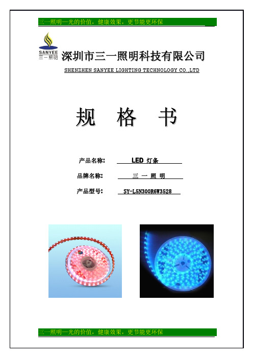
三一照明 SY-L5N300R6W3528 LED灯条 说明书
无噪音,发热少:LED 灯具使用时不会产生噪音,发热也比传统灯少很多。 无噪音, 响应时间快:没有了传统灯启动时的闪烁,即开即亮。
五:安装方法与注意事项:
1、 室内安装:LED 灯带用于室内装饰时,由于不必经受风吹雨打,所以安装就非常简单。 以光虹电子生产的 LED 灯带为例,每款 LED 灯带的背后都贴有自粘性 3M 双面胶,安装 时可以直接撕去 3M 双面胶表面的贴纸,然后把灯条固定在需要安装的地方,用手按平 就好了。至于有的地方需要转角或者是长了怎么办?很简单,LED 灯带是以 3 个 LED 为 一组的串并联方式组成的电路结构,每 3 颗 LED 即可以剪断单独使用。 2、 户外安装:户外安装由于会经受风吹雨淋,如果采用 3M 胶固定的话,时间一久就会造 成 3M 胶粘性降低而致使 LED 灯带脱落,因此户外安装常采用卡槽固定的方式,需要剪 切和连接的地方,方法和室内安装一样,只是需要另外配备防水胶,以巩固连接点的防 水效果。 3、 电源连接方法:LED 灯带一般电压为直流 12V,因此需要使用开关电源供电,电源的大 小根据 LED 灯带的功率和连接长度来定。 如果不希望每条 LED 灯带都用一个电源来控制, 可以购买一个功率比较大的开关电源做总电源,然后把所有的 LED 灯带输入电源全部并 联起来(线材尺寸不够的话可以另外延长) ,统一由总开关电源供电。这样的好处是可 以集中控制,不方便的地方是不能实现单个 LED 灯带的点亮效果和开关控制,具体采用 哪种方式可以由自己去衡量。 4、 控制器连接方式:LED 跑马灯带和 RGB 全彩灯带需要使用控制器来实现变幻效果,而每 个控制器的控制距离不一样,一般而言,简易控制器的控制距离为 10 到 15 米,遥控控 制器的控制距离为 15 到 20 米,最长可以控制到 30 米距离。如果 LED 灯带的连接距离 较长,而控制器不能控制那么长的灯带,那么就需要使用功率放大器来进行分接。 5、 注意 LED 灯带的连接距离:一般来说,3528 系列的 LED 灯带,其连接距离最长为 20 米, 5050 系列的 LED 灯带,最长连接距离为 15 米。如果超出了这个连接距离,则 LED 灯带 很容易发热,使用过程中会影响 LED 灯带的使用寿命。因此,安装的时候一定要按照厂 家的要求进行安装,切忌让 LED 灯带过负荷运行。
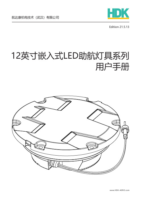
12英寸嵌入式LED助航灯具系列用户手册说明书
Edition 21.5.13 12英寸嵌入式LED助航灯具系列用户手册航达康机电技术(武汉)有限公司Hangdakang Mechanical & Electrical Technology (Wuhan) Co., Ltd.地址:武汉市东湖新技术开发区佛祖岭光谷光机电产业园10号楼网址: 邮箱:airport@hdk 12英寸嵌入式LED 助航灯具系列用户手册免责申明目录1.02.0 安全须知产品简介56789102.1 2.2 2.3 2.4 产品型号产品特点机械参数电气参数2.5 产品组件11122.6 灯具标记说明132.6.1 窗口编号2.6.2 2.6.3 窗口发光标记铭牌1313153.0 161616安装3.1 3.2 工具准备包装拆卸3.4 灯具拆卸173.3 安装在12英寸嵌入式灯具底座4.1 4.2 4.3 一般维护程序工具准备维护项目181920204.0 19维护4.0 192122232527维护4.4 操作步骤4.4.1 4.4.2 灯体拆装驱动模块拆装4.4.3 4.4.4 光学组件拆装棱镜压板拆装2828294.4.5 4.4.6 失效断开重启电源线拆装4.5 故障分析5.06.0 3034343434备件及工具服务支持6.1 6.2 6.3 售后服务回收利用关于航达康12英寸嵌入式LED 助航灯具系列用户手册表1 跑道灯具清单进近灯具清单隔离变压器规格要求表2 表3 表格目录791819192021293031嵌入式灯具一般维护计划螺丝/螺丝垫片规格表部署状态的灯具维护项目非部署状态灯具维护项目故障分析表备件清单(3窗口12英寸嵌入式灯具)备件清单(嵌入式跑道边灯)备件清单(5窗口12英寸嵌入式灯具)表4 表5 表6表7 表8 表9 安装附件/工具表10 表11 表12 3233图1 12英寸嵌入式灯具系列图2 12英寸嵌入式灯具系列主要尺寸图3 12英寸嵌入式灯具结构爆炸图图4 12英寸嵌入式灯具窗口编号示意图12英寸嵌入式灯具底座安装示意图图5 图6 图7灯体拆装示意图图8 驱动模块拆装示意图光学组件拆装示意图棱镜压板拆装示意图灯具电源线拆装示意图图9 图10 光学组件拆装示意图(带盘旋引导)图11 图片目录71112131722232526272812英寸嵌入式LED助航灯具系列用户手册免责申明航达康机电技术(武汉)有限公司(以下简称“航达康”或“本公司”)的助航灯具产品符合中国民航总局、国际民航组织和国际电工委员会的要求。
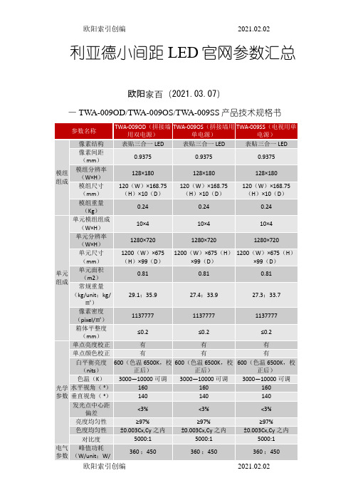
利亚德小间距LED官网参数整理
像素密度(pixel/㎡)
360000
360000
箱体平整度(mm)
≤0.2
≤0.2
光学
参数
单点亮度校正
有
有
单点颜色校正
有
有
白平衡亮度(nits)
600(色温6500K,校正后)
600(色温6500K,校正后)
色温(K)
3000—10000可调
3000—10000可调
水平视角(°)
AC100~240V(50-60Hz)
电源配置
双电源
单电源
单电源
处理
性能
驱动方式
恒流驱动
恒流驱动
恒流驱动
换帧频率(Hz)
50&60
50&60
50&60
刷新率(Hz)
1920
1920
1920
使用
参数
寿命(hrs)
50,000
50,000
50,000
工作温度范围(℃)
-10 -- 40
-10 -- 40
0.24
0.24
单元
组成
单元模组组成(W×H)
10×4
10×4
10×4
单元分辨率(W×H)
1280×720
1280×720
1280×720
单元尺寸(mm)
1200(W)×675(H)×99(D)
1200(W)×675(H)×99(D)
1200(W)×675(H)×99(D)
单元面积(m2)
0.81
0.81
3000—10000可调
3000—10000可调
3000—10000可调
强力巨彩P4模组Q4E16V8.5(8个铜螺母)规格书

产品规格书SPECIFICATION产品名称:室内P4十六扫全彩表贴三合一单元板规格型号:Q4E16V8.5文件编号:版本编号: 1.0目录目录 (1)1.适用范围 (2)2.产品说明 (2)3. 产品介绍 (3)4. 信号引脚定义 (4)5. 规格型号说明 (4)6. 线路原理图 (4)7. IC贴片图 (5)8. 安装孔位图 (5)9. 安装指导方式 (10)10. 软件安装 (12)11. 开关电源配置参数 (13)12. 产品使用注意事项 (13)13. 单元板备件 (16)1. 适用范围本技术手册仅适用于室内Q4E16V8.5(64*32)十六扫全彩表贴三合一单元板。
2. 产品说明2.1. 室内P4.0十六扫全彩表贴三合一单元板主要是由红色LED晶片、绿色LED晶片和蓝色LED晶片封装为一个像素点后组成矩阵,再固定到塑胶套件上而成;2.2. 此单元板含有驱动芯片和输入缓冲芯片,连接到LED显示屏控制系统即可显示视频、图像和文字信息等;2.3. 通过OE信号驱动红色LED、绿色LED和蓝色LED的驱动芯片,可形成43980亿种颜色变换;2.4. 此单元板可以按水平和垂直方向任意拼接,从而拼成不同大小的显示屏;2.5. 单元板的特点:●用超高亮的LED和优质的塑胶件●高对比度可达到良好的显示效果●重量轻易于安装、拆卸●可进行单点、单灯维护,成本低●采用恒流方式驱动LED,发光均匀,功耗低●像素间距为4.0mm,共有64*32个像素点,每个像素点由1R1G1B组成2.6. 单元板图片3.产品介绍3.1LED参数:3.2屏体技术参数:4.信号引脚定义HUB75C5.规格型号说明产品型号命名规范:6.线路原理图7.IC贴片图8.安装孔位图8.1单元板安装孔位:备注:“如有制作箱体,请提前告知办事处并确认订单产品孔位图”所有尺寸的单位为mm。
8.4压铸箱实物图:正面视图背面视图正面侧视图背面侧视图8.5压铸箱实物说明图:镀铬提手9.安装指导方式9.1箱体屏安装简介:9.1.1安装方式(显示屏安装结构简易图)注:以上为目前显示屏安装中常用的六种安装方式,对于室内显示屏一般采A\B\C\D四种安装方式,户外显示屏以上方式均可采用。
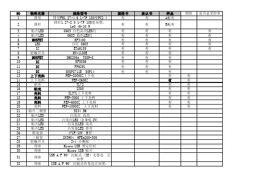
常用机型需样品与承认书
PEP-2600Z Rev.1.1 TL72-A Rev.2.3 TL72-B Rev.2.3 2200AW-B-V1.0 2200AW-V1.0 IL37L-V1.1 PEP-20000Z V1.1(4L) PEP-6000Z VER:1.0B PEP-10000Z-V1.0Bpcb SEA103J-F1-050(1mm镀锡) 2Байду номын сангаас3904 2N7002 SOT-23 AO3400A SOT-23 AO3401 SOT-23 AO8822 2N7002 8205S SOT23-6 AO3400 SOT23-3 Micro 5P 牛角 MICRO 5P母座4脚长脚长针有柱 白发白高亮(赣洪) 白发红 高亮 0603 白发蓝 高亮 0603 SY7065 CW3002D SOT23-5 DW01 DW01+ SOT-23 KF9108 KF9109 SOT23-5
NO 1 2 3 4 5 6 7 8 9 10 11 12 13 14 15 16 17 18 19 20 21 22 23 24 25 26 27 28 29 30 31 32
规格型号 排母FH1.27*4.6 1*7P 180度PC2.4 排针1.27*2.0 1*7P 180度双塑, 排针 L=0.46*10.9 贴片LED 0603 白色高亮LED灯 贴片LED 0603 蓝色LED灯 MOSFET KF3400 LED 白灯 0603 IC ETA6185 轻触开关 HY-1188E MOSFET SM8205A TSSP-8 IC KF5056 IC FP6291 IC SN8P2711B SOP14 上下壳料 PEP-20000Z上下壳 上下壳料 PEP-2600Z 铝壳 TL72 铝壳 2200 壳料 IL37L上下壳料 壳料 PEP-3000 上下壳料 壳料 PEP-6000Z 上下壳料 壳料 PEP-10000Z 上下壳料 贴片二极管 SS34 SM 贴片LED 白发红 高亮 贴片LED 白发红LED (2.0-2.2V) 贴片LED 白发蓝LED 高亮 贴片LED 白发蓝LED 普亮 钽电容 47UF/10V B型 三极管 2N3904 HFE=200-300 轻触开关 2*4 小侧按 母座 Micro USB 带定位柱 母座 Micro USB 贴片 USB A/F 90°沉板式(3E)无卷边 正 母座 向型 母座 USB A/F 90°沉板式有卷边正向型,
Viscor LTRI-LED三光源LED亮灯架型号说明书
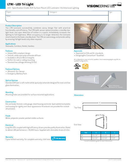
Option V69 shown(Ultrasonic Occ Sensor)Features• Unique ADA compliant design• Smooth, white opal polycarbonate diffuser • Available in 24 and 48 inch lengths • Perfect for wall or ceiling mounting • Standard low voltage dimming (0-10v)Featured Options• Ultrasonic Occ Sensor • Emergency Battery PackOptical SystemStandard diffuser is soft matte white opal polycarbonate designed for even and low glare illumination.MountingMounting holes are provided for surface mounted applications.ConstructionDie and brake-formed, code gauge, steel housing and ends. Spot-welded end plates and housing for rigidity and clean appearance. Knockouts are provided for conduit attachment.FinishWhite, polyester powder painted visible surfaces.ElectricalLong life LEDs coupled with high efficiency drivers provide quality illumination. Rated to deliver L80 performance > 50,000 hours. Supplied with dimmable drivers (0-10v).Warranty5 year limited warranty. For complete warranty, click here:Consult installation guide for exact dimensions.Product DescriptionThe LTRI luminaire successfully combines savvy design flair with practical functionality and efficiency. The LTRI (with sensor option) provides a standby low-light level, and upon detection of motion in a space, immediately increases the lighting to full brightness. When occupancy is no longer detected, the luminaire reverts back to the lower, standby level. The LTRI can save energy and provide safety by ensuring full light levels only when required.ApplicationsStairwells, Corridors, Hotels, Vanities Approvals• Approved to CSA and UL standards.• DesignLights Consortium ® Qualified.All configurations may not be DLC qualified. Check /QPL for qualified configurations..DimensionsTop ViewEnd ViewOrder Key50K - 5000K 010L - 1000016L - 1600018L - 1800037L - 3700050L - 5000Driver OptionsB15 Bi-Level Step Dimming (50/100)(Not available in 24-inch length or 347V)B39 Emergency Lighting Battery Pack - LED(Not available in 24-inch length)Housing Construction OptionsC03 Fasteners Tamper ProofC65 Housing for Front Facing SensorFinish OptionsWhite, polyester powder painted is standardF01 Black SatinF14 Silver ReflectivePackaging OptionsK0 Bulk Pack/Pallet Packed and/or WrappedK1Pack SingleSensor Options(Not to be used in conjunction with B15 option)(Not suitable for chain/cable suspension)V69 Ultrasonic Occupancy Sensor(Capable of 0% / 10% / 25% / 50%)Controls OptionsTo visw the controls guide Click Here.Other options may be available, consult factory. Specifications and datasubject to change without notice.48”EXAMPLE: LTRI48- LED835K037LUNV-V6924”Sensor PlacementPerformance DataValues based on 840K with standard lens at 25CPhotometrics。
J30J系列微型矩形电连接器
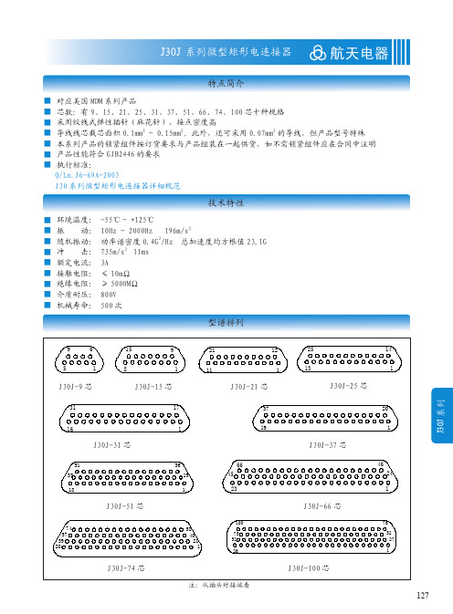
128
J30J 系列微型矩形电连接器
线夹合件族谱树
A1型线夹合件 线夹合件 A2型线夹合件 A3型线夹合件
航天电器
只能与"压接基本型"插头(座)合件配套使用。 只能与J30J-TJ-Q8/ZK-Q8插头(座)合件配套使用。 是"焊接基本型"插头(座)合件的默认配件。 还可与"压接基本型"插头(座)合件配合使用。
129
J30J 系列
航天电器
J30J 系列微型矩形电连接器
订货标志
J30J ①
×
②
- ×
③
TJ/ZK
④
×
×
- ×
×
(附加说明)
⑤ ⑥
⑦ ⑧
① 主称代号: ② 系列改型:不表示 - 基本型 A - 快锁型 C - 外壳材料为锡磷青铜并镀镍 D - 安装孔改为 M2-6H M - 胶密封 M1 - 玻璃烧结密封 ③ 接触件数目:9、15、21、25、31、37、51、66、74、100 ④ 连接器与接触件种类: TJ - 插头装插针 ZK - 插座装插孔 TJ、ZK 为固定搭配 ⑤ 尾端形式: 无字母 - 压接 S - 焊接 N - 直插印制板 W - 弯插印制板 ⑥ 锁紧组件类别:详见 J30J 锁紧组件 ⑦ 表面涂覆: 无字母 - 外壳镀镍 G - 外壳镀镉 ⑧ 基本改型:A - 外壳尾端带屏蔽网线夹 C - 用于产品出线方向与接触件轴向垂直时 D - 插座外壳法兰对接端上带有防转槽 AD - 改型 A 与改型 D 的结合 Q - 外壳法兰加宽 J - 印制板网格间距为 1.27×2.54(列 × 行) 注:附加说明不是订货标志的组成部分,顾客在选用时请在括号中注明压接的导线规格如:导线截面积、 长度和颜色等。有特殊连线要求时,请给出连线关系。
MT3111断点续传单线恒流驱动LED控制芯片说明书
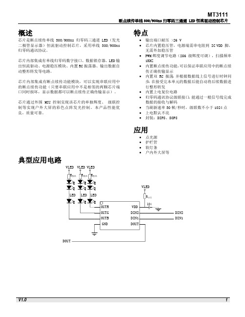
概述芯片是断点续传单线300/900ns归零码三通道 LED(发光二极管显示器)恒流驱动控制芯片,采用单线300/900ns 归零码通讯协议。
芯片内部集成有单线归零码数字接口、数据锁存器、LED输出恒流驱动、电源稳压模块、内置RC振荡器、输出数据自动整形转发等电路。
芯片内部集成有断点续传功能模块,可以实现串联应用中的断点续传功能(只要串联应用中不是相邻的两颗芯片端口同时损坏,显示数据都可以断点续传正确传输显示)。
芯片通过外围 MCU 控制实现该芯片的单独辉度、级联控制等实现户外大屏的彩色点阵发光控制。
本产品性能优良,质量可靠。
特点∙输出端口耐压 >26 V∙芯片内置稳压管,电源端需串电阻到 IC VDD 脚,无需外加稳压管∙PWM辉度调节电路(256 级辉度可调),扫描频率1KHZ∙内置断点续传功能,可以保证串联应用中的断点续传正确传输显示∙内置双 RC 振荡,并根据数据线上信号进行时钟同步,在接受完本单元的数据后能自动将后续数据进行整形转发∙内置上电复位电路∙归零码通讯协议级联接口,能通过一根信号线完成数据的接收与解码∙当刷新速率30帧/秒时,级联数不小于1024点∙上电默认不亮∙封装:DIP8、SOP8应用∙点光源∙护栏管∙软灯条∙户内外大屏等典型应用电路DIN2DIN1SOP8/DIP8封装管脚(800K传输速率断点续传功能)OUTR OUTG OUTB GNDVDDDIN2DIN1DOUT SOP8/DIP8极限参数推荐工作范围(无特殊说明,TA=-40~+85℃,GND=0V)电气参数开关特性内部框图DOUTVDD GND功能描述芯片采用单线归零码协议通讯传输。
芯片在上电复位以后,接收DIN 端口传输的数据,接受24 bit 后,DOUT 端口开始转发数据,提供下一个芯片的输入数据。
在转发之前,DOUT端口一直拉低。
此时芯片将不接收新的数据,芯片OUTR、OUTG、OUTB三个PWM输出口根据接收到的24 bit 数据,发出相应的不同占空比的信号,该信号周期在1 ms 左右。
J30J 系列微型矩形电连接器——航天电器
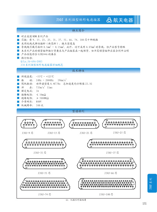
30.86
8.7
25
26.6
5.8
7.9
42.9
37.3
8.7
31.4
33
5.8
7.9
38.8
33.5
9.7
27.5
29.1
6.8
9.1
54.7
45.7
9.7
35
36.6
6.8
9.1
19.6
14.3
7.6
9.8
9.9
6.1
6.8
23.5
18.2
7.6
13.7
13.8
6.1
6.8
27.4
22
7.6
17.4
2、因焊接基本型插头(座)合件(J30J-TJS/ZKS)默认配装有 A3 型线夹合件,所以在其基础上扩展而 来的 J30J-TJS/ZKS-G 插头(座)合件也要默认配装 A3 型线夹合件。为保持线夹与外壳镀层相同,线夹 也应镀镉。
3、型号中含有大写字母“D”的插头(座)合件不能配装 L、L1 ~ L8、K、K1 型等锁紧组件。
J30J 系列微型矩形电连接器
航天电器
特点简介
■ 对应美国 MDM 系列产品 ■ 芯数:有 9、15、21、25、31、37、51、66、74、100 芯十种规格 ■ 采用绞线式弹性插针(麻花针),接点密度高 ■ 导线线芯截芯面积 0.1mm2 ~ 0.15mm2。此外,还可采用 0.07mm2 的导线,但产品型号特殊 ■ 本系列产品的锁紧组件按订货要求与产品组装在一起供货,如不需锁紧组件应在合同中注明 ■ 产品性能符合 GJB2446 的要求 ■ 执行标准:
(J30J-TJN/ZKN) (J30J-TJN-J/ZKN-J) (J30J-TJW/ZKW) (J30J-TJW-J/ZKW-J)
IS31LT3916开关针轻量型LED驱动演示板用户指南,由集成随机解决方案公司制造,官方网站为ww

DescriptionThe IS31LT3916 is a primary side, peak current mode, isolated or non-isolated type HBLED driver. The device works at a constant frequency in discontinuous conduction mode to provide a constant power to the output. It eliminates the need for an opto-coupler, TL431, or any other type of secondary side feedback. It operates from a wide input voltage range of 90VAC to 260VAC. The IS31LT3916 integrates over currentprotection, over voltage protection, as well as includes a thermal shutdown to halt the switching action in the case of abnormally high operating temperatures.Features● Power factor correction to > 0.90 ● 5% typical current accuracy ● High efficiency● No loop compensation required● Wide input voltage range: 90V to 260VAC ● Isolation and Non-isolation application ● Internal over-temperature protection ● Over voltage protection● Primary side over current protectionApplications● LED bulb lamp ● LED tube lamp ● General LED lampOrder informationPart NumberPackage TypeIS31LT3916-SLS2-EBT8 MSOP-8Quick StartRecommended Equipment● 90~260VAC/50~60Hz power supply ● LED array(12 LEDs in series)Recommended Input and Output Ratings● Input: 90~260VAC● Output: 12LEDs in series(40V/450mA)Absolute Maximum Ratings≤ 265VAC power supply ≤ 50V Vout (Total Vf)Caution: Do not exceed the conditions listed above, otherwise the board will be damaged or the output will be limited.ProcedureThe IS31LT3916 DEMO Board is fully assembled and tested. Follow the steps listed below to verify board operation.Caution: Do not turn on the power supply until all connections are completed.1) Connect the positive terminal of the LEDsto the LED+ pin of the DEMO and the negative terminal of the LEDs to the LED- pin of the DEMO. 2) Connect the input pins (L and N) of theDEMO via the main power switch to AC power supply. 3) Turn on the power supply.Figure 1 Picture of DEMO BoardNOTE: Physical dimensions are (L x W x H): 255mm x 17mm x 12mmBill of MaterialsNo. Name Description RefDes. Qty.Cost(RMB)1 Fuse 1A,250V,3*10 F1 10.12 MOV 7D471K MOV 10.13 XCap 0.1uF,275VAC CX1,CX2 2 0.34 YCap JN102M CY 10.155 SMDCap NC C1,C5 1 06 SMDCap 1nF±10%,500V,1206 C2 1 0.17 ALCap 330uF±10%,63V,10mm*20mm C3,C4 2 0.48 CBBCap 100nF±10%,400V C6 1 0.159 SMDCap 1nF±10%,16V,0805 C7 1 0.0410 SMDCap 1uF±10%,50V,0805 C8 1 0.111 SMDCap 10uF±10%,50V,1206 C9 1 0.112 SMDCap 1uF±10%,50V,1206 C10 1 0.113 RectifyingBridge DB107,1A,1000V,DB-1 BD1 1 0.314 FRDiode ES2G,2A,400V,SMA D1 1 0.1515 FRDiode RS1M,1A,1000V,SMA D2 1 0.1516 SMDDiode 1N4148,200mA,75V,LL34 D4 1 0.0517 SMDDiode NC D3 1 018 SMDDiode M7,1A,1000V,SMA D5 1 0.0519 SMDResistor NC R1 1 020 SMDResistor 4.7KΩ±5%,0805 R210.006 21 SMDResistor NC R4 1 022 SMDResistor 180KΩ±5%,1206 R3,R2410.016 23 SMDResistor 1MΩ±1%,1206 R5,R7,R930.024 24 SMDResistor 180KΩ±5%,1206 R6,R1020.016 25 SMDResistor 62KΩ±5%,1206 R810.008 26 SMDResistor 910KΩ±1%,1206 R1110.008 27 SMDResistor 30Ω±5%,0805 R1210.006 28 SMDResistor NC R14 1 029 SMDResistor 2.2MΩ±1%,0805 R1510.006 30 SMDResistor 13KΩ±1%,0805 R1610.006 31 SMDResistor 240KΩ±1%,0805 R1710.006 32 SMDResistor 13KΩ±1%,0805 R1810.006 33 SMDResistor 20KΩ±1%,0805 R1910.006 34 SMDResistor 1.2Ω±1%,1206 R13,R20,R21,R21-240.03235 SMDResistor 160KΩ±1%,0805 R2210.006 36 SMDResistor 10KΩ±1%,0805 R2310.006 37 Inductor 3mH±10%,8*10mm,Isat≥200mA L110.1538 Common ModeChockEE12,L2-1=L2-2=30mH±10%,0.25mm,90TsL2 10.339 Inductor NC L3 1 02.5=23:12:5,Lp=0.41mH±5% TR 140 Transformer ER4008,Tp:Ts:Ta41 NMOS 6N80,6A/800V,TO-220 Q1 1 1.8x17mm 1 142 PCB 255mm43 IC IS31LT3916,MSOP-8 U1 1 -Total Cost(Exclude IC) 8.239Figure 2.Schematic of DEMO BoardFigure 3 PCB Layout- Top LayerFigure 4 PCB Component Placement Guide - Top LayerFigure 5 PCB Layout- Bottom LayerTransformer Design ELECTRICAL SPECIFCATIONS:1. Primary inductance (Lp)=410uH@10kHz2. Primary Leakage Inductance (Lk) < = 20uH @10KHz3. Electrical Strength = 3KV, 50/60Hz, 1MinMATERIALS:1. Core: ER4008 (Ferrite Material TDK PC40 or equivalent)2. Bobbin: ER4008, Primary 5pins, Secondary 3pins3. Magnet Wires (Pri&Aux): Type 2-UEW4. Magnet Wire (Sec): Triple Insulated Wires5. Layer Insulation Tape: 3M1298 or equivalentFigure 6 TransformerNO. winding Start Endnumber of turns number of pliesdiameternumber of pliestape remarks1 NP 3 1 23T2 0.30mm-2-UEW 2 0.02*4mm 2 NS 6 7 12T 2 0.40mm-TEX3 0.02*4mm3 NA4 55T1 0.13mm- 2-UEW 3 0.02*4mmTest resultInput voltage(VAC) PF THD(%) Input power(W)Output voltage(V)Output current(mA)Outputpower(W)Efficiency(%)90 0.999 1.7 21.04 40.2 440 17.69 84.07 100 0.999 1.7 21.33 40.2 448 18.01 84.43 110 0.998 1.7 21.10 40.2 447 17.97 85.16 120 0.997 1.7 21.22 40.2 450 18.09 85.25 130 0.997 1.7 21.62 40.2 460 18.49 85.53 140 0.996 1.7 21.25 40.2 456 18.33 86.26 150 0.995 1.7 21.29 40.2 456 18.33 86.10 160 0.994 1.7 21.36 40.2 457 18.37 86.01 170 0.992 1.9 21.29 40.2 460 18.49 86.86 180 0.990 1.9 21.37 40.2 460 18.49 86.53 190 0.987 1.9 21.22 40.2 457 18.37 86.58 200 0.984 1.9 20.94 40.2 451 18.13 86.58 210 0.980 2.0 21.14 40.2 456 18.33 86.71 220 0.977 2.0 21.21 40.2 457 18.37 86.62 230 0.973 2.0 21.16 40.2 456 18.33 86.63 240 0.968 2.0 21.25 40.2 457 18.37 86.45 250 0.962 2.1 21.18 40.2 456 18.33 86.55 260 0.957 2.1 21.02 40.1 452 18.13 86.2320025030035040045050085110135160185210235260O u t p u t c u r r e n t (m A )Vin(VAC)5055606570758085909510085110135160185210235260E f f i c i e n c y (%)Vin(VAC)Figure 7 Line regulation Figure 8 Efficiency&Vin123456789100.50.550.60.650.70.750.80.850.90.95185110135160185210235260T H D (%)P FVin(VAC)PF THDFigure 9 PF,THD&VinEMI testFigure 10 Conduction EMI_LFigure 11 Conduction EMI_NCopyright © 2013 integrated Silicon Solution, Inc. All rights reserved. ISSI reserves the right to make changes to this specification and its products at any time without notice. ISSI assumes no liability arising out of the application or use of any information, products or services described herein. Customers are advised to obtain the latest version of this device specification before relying on any published information and before placing orders for products.。
利亚德小间距LED官网参数

600(色温6500K,校正后)
600(色温6500K,校正后)
色温(K)
3000—10000可调
3000—10000可调
3000—10000可调
水平视角(?°)
160
160
160
垂直视角(?°)
140
140
140
发光点中心距偏差
<3%
<3%
<3%
亮度均匀性
≥97%
≥97%
三?TWA-014OD/?TWA-014OS产品技术规格书
参数名称
TWA-014OD(拼接墙用双电源)
TWA-014OS(拼接墙用单电源)
模组
组成
像素结构
表贴三合一LED
表贴三合一LED
像素间距(mm)
1.49
1.49
模组分辨率(W×H)
161×113
161×113
模组尺寸(mm)
240(W)×168.75(H)×10(D)
利亚德小间距LED官网参数
利亚德小间距LED官网参数汇总
一?TWA-009OD/TWA-009OS/TWA-009SS产品技术规格书
参数名称
TWA-009OD(拼接墙用双电源)
TWA-009OS(拼接墙用单电源)
TWA-009SS(电视用单电源)
模组
组成
像素结构
表贴三合一LED
表贴三合一LED
表贴三合一LED
29.1;35.9
27.4;33.9
27.3;33.7
像素密度(pixel/㎡)
1137777
1137777
1137777
箱体平整度(mm)
LED产品说明书-型号SBT-90-G

Applications• Architectural and Entertainment Lighting • Fiber-coupled Illumination • Medical Lighting• Machine Vision • Microscopy • Spot Lighting•• Round emitting aperture provides most efficient match to circular optical systems and narrow beam projectors • Unencapsulated die with low profile protective window optimizes optical coupling in etendue-limited applications• High thermal conductivity package - junction to case thermal resistance of only 0.64°C/W • Variable drive current up to 10.5 A continuous wave. Up to 2 A/mm 2 in pulsed conditions • RoHS and REACH compliantTable of ContentsTechnology Overview . . . . . .2Ordering Information . . . . . .3Binning Structure . . . . . . . . . .4Typical DevicePerformance . . . . . . . . . . . . . . .5Absolute MaximumRatings . . . . . . . . . . . . . . . . . . . .6Optical & ElectricalCharacteristics . . . . . . . . . . . . . .7Angular Distribution &Typical Spectrum . . . . . . . . . .9Soldering Profile . . . . . . . . .10Mechanical Dimensions . .11Shipping Tray Outline . . . .13Shipping Label . . . . . . . . . . .14Revision History . . . . . . . . . .15SBT-70-G/BLEDsUnderstanding Big Chip LED Test SpecificationsEvery Luminus LED is fully tested to ensure that it meets the high quality standards expected from Luminus’ products .Luminus TechnologyLuminus’ technology enables large area LED chips with uniform brightness over the entire LED chip surface . The optical power and brightness produced by these large monolithic chips enable solutions which replace arc and halogen lamps where arrays of traditional high power LEDs cannot .Packaging TechnologyThermal management is critical in high power LED applications . With a thermal resistance from junction to case of 0 .64°C/W, Luminus SBT-70 LEDs have the lowest thermal resistance of any LED on the market . This allows the LED to be driven at higher current densities while maintaining a low junction temperature, thereby resulting in brighter solutions and longer lifetimes .ReliabilityThis product is sensitive to static electricity, and care should be taken when handling them . Static electricity or surge volt-age will damage the LEDs . It is recommended to wear an anti-electrostatic wristband or anti-electrostatic gloves when han-dling the LEDs . All devices, equipment and machinery must be properly grounded . It is recommended that measures be taken to isolate LED processing equipment from potential sources of voltage surges .Reference: APN-002815 Electrical Stress D amage to LED s and How to Prevent ItEnvironmental BenefitsLuminus LEDs help reduce power consumption and the amount of hazardous waste entering the environment . All LED products manufactured by Luminus are RoHS compliant and free of hazardous materials, including lead and mercury .Technology OverviewLuminus LEDs™ benefit from a suite of innovations in the fields of LED die technology, packaging and thermal management . These breakthroughs allow illumination engineers and designers to achieve solutions that are high brightness and high efficiency .Testing TemperatureLuminus surface mount LEDs are typically tested with a 20 ms single pulse and a case temperature of 25°C . Expected flux values in real world operation can be extrapolated based on the information contained within this product data sheet .Ordering InformationNote 1: Flux Bin listed is minimum bin shipped, higher bins may be included at Luminus’ discretion .SBT 70<C>F75<Bin kit>The table below lists ordering part numbers available for SBT-70 LEDs . The part number includes a bin kit, a group of flux and wavelength bins described in page 4, that are shippable for a given ordering part number .Ordering Part NumbersPart Number NomenclatureSBT-70 G/B Binning StructureSBT-70 monochromatic LEDs are tested for luminous flux and dominant wavelength at a 10 .5 A (1 .5 A/mm 2) drive current and placed into one of the following flux and wavelength bins . The binning structure is universally applied across each monochromatic color .Flux BinsNote 1: Luminus maintains a +/- 6% tolerance on flux measurements .Note 2: Products are production tested then sorted and packed by bin .Note 3: Individual bins are not orderable . Please refer to the Product Ordering information page for a list of orderable bin kits .Note 4: Product test condition: 10 .5 A DC, 25°C constant case temperature .Note 5: T c = Case Temperature . Wavelength BinsTypical Device PerformanceFor notes see page 6 .Absolute Maximum RatingsNote 1: Listed drive conditions are typical for common applications . SBT-70 G,B devices can be driven at currents ranging from 1 A to 10 .5 A and at duty cycles ranging from 1% to 100% . Drive current and duty cycle should be adjusted as necessary to maintain the junction temperature desired to meet application lifetime requirements .= 25°C .Note 2: All ratings are based on a constant case temperature TcNote 3: Unless otherwise noted, values listed are typical . Devices are production tested and specified at 10 .5 A . Other values are for reference only .Note 4: Total flux from emitting area at listed dominant wavelength . Reported performance is included to show trends for a selected power level . For specific minimum and maximum values, use bin tables . For product roadmap and future performance of devices, contact Luminus .Note 5: In CIE 1931 chromaticity diagram coordinates, normalized to X+Y+Z=1 .Note 6: For reference only .Note 7: Caution must be taken not to stare at the light emitted from these LEDs . Under special circumstances, the high intensity could damage the eye .Note 8: Measurements are in accordance with JEDEC 51-14 . For more about thermal resistance calculation, please see h ttps://luminusdevices .zendesk .com/hc/en-us/articles/4416807960717-Thermal-Heatsink-Required-Rth-CalculatorNote 9: For more about calculating thermistor temperature, please see https://luminusdevices .zendesk .com/hc/en-us/articles/4412023747341-How-do-I-determine-the-temperature-from-Luminus-on-board-Thermistor-Note 10: Luminus LEDs are designed for operation to an absolute maximum current as specified above . Product lifetime data is specified at recommended forward drive currents . Sustained operation at or beyond absolute maximum currents will result in a reduction of device lifetime compared to recommended forward drive currents . Actual device lifetimes will also depend on junction temperature . Refer to the lifetime derating curves for further information . In pulsed operation, rise time from 10-90% of forward current should be larger than 0 .5 microseconds .Note 11: Lifetime dependent on LED junction temperature . Input power and thermal system must be properly managed to ensure lifetime .Relative Luminous Flux vs. Forward Current - BlueForward Current vs. Forward Voltage - BlueRelative Luminous Flux vs. Forward Current - GreenForward Current vs. Forward Voltage - GreenOptical & Electrical CharacteristicsNote 1: Median lifetime estimate as a function of junction temperature at 1 .5 A/mm 2 in continuous operation . Lifetime defined as time to 70% of initialintensity . Based on preliminary lifetime test data . Data can be used to model failure rate over typical product lifetime .Note 2: Lumen maintenance vs . time at 1 .5 A/mm 2 in continuous operation, case temperature equal to 25°C .Optical & Electrical CharacteristicsHeat Sink Temperature vs. Relative Luminous FluxHeat S ink T emperature v s. R elative D ominant W avelength ShiftMedian Lifetime Estimate vs. Junction Temperature 1Lumen Maintenance 2Angular Intensity Distribution (Typical)Typical SpectrumIref= f(Φ); T c = 25°CΦref = f(λ); I f = 10.5 A ; T c = 25°CSoldering ProfileT e m p e r a t u r eReflow 180 to T L + 20°C 3 - 6°C/secCool down Peak to below 150°C3 - 7°C/secPeak Temperature (235 - 245°C)Time Above Liquidus (45 - 90 sec)Note 1: Product complies to Moisture Sensitivity Level 3 (MSL 3)Note 2: The numbers in the table are specific to SAC305 . Luminus recommends using an SAC305 solder paste with a no-clean flux for RoHS compliantproducts .Note 3: During the pick and place process, axial forces on the dome (or window) should not exceed 0 .5 Newtons (N)Note 4: Use of a multi-zone IR reflow oven with a nitrogen blanket is recommended .Note 5: Time-temperature profile of the reflow process showing the four functional profile zones are defined in IPC-7801 . Temperature is referenced tothe center of the PCB .Note 6: Luminus recommends to use the solder paste data sheet information as a starting point in time-temperature process development .Note 7: These are general guidelines . Consult the solder paste manufacturer’s datasheet for guidelines specific to the alloy and flux combination usedin your application . For more information, please refer to: https://luminusdevices .zendesk .com/hc/en-us/articles/360060306692-How-do-I-Reflow-Solder-Luminus-SMD-Components-Note8:Foranytechnicalquestionsaboutsolderingprocess,*********************************************.Note 9: This part is not compatible with vapor phase reflow processes .Mechanical Dimensions – SBT-70 EmitterNote 1: Tolerances per IPC-610, Class 2 . All dimensions in millimeters Note 2: For detail drawing of SBT-70, please see page 11 .Note 3: Recommended mounting screw: M3 or #4Note 4: All anode pads and all cathode pads on board are interconnected .1100 TECHNOLOGY PARK DRIVE1 OF 1CBA16/1DRAWING, OUTLINE, 002153, SBR-70BILLERICA, MA 01821978-528-800001B SCALE:NUMBER:SIZE:REV: DIMENSIONS ARE IN (UNLESS OTHERWISE SPECIFIED):SHEET:DWG-002153Shipping Tray Outline工程專用發行章Engineering StampIQC4.36110.626.89175.013.7695.586.22157.94A ABB.0200.51.40510.297.0°TYPSECTION A-AR.0300.76TYPSECTION B-BECO DESCRIPTION OF CHANGE REVLabel Fields:• CPN: Luminus ordering part number • CID: Customer’s part number • QTY: Quantity of devices in pack • Flux: Bin as defined on page 4• Voltage: NA• Color: Bin as defined on p age 4• CRI: NAShipping LabelPacking Configuration:• Maximum stack of 2 trays per pack with 25 devices per tray • Partial pack or tray may be shipped • Each pack is enclosed in anti-static bag •Shipping label is placed on top of each packXXX-XX-XXXX-XXXX-XXXXXXXXX50Box IDRevision HistoryThe products, their specifications and other information appearing in this document are subject to change by Luminus Devices without notice . Luminus Devices assumes no liability for errors that may appear in this document, and no liability otherwise arising from the application or use of the product or information contained herein . None of the information provided herein should be considered to be a representation of the fitness or suitability of the product for any particular application or as any other form of warranty . Luminus Devices’ product warranties are limited to only such warranties as accompany a purchase contract or purchase order for such products . Nothing herein is to be construed as constituting an additional warranty . No information contained in this publication may be considered as a waiver by Luminus Devices of any intellectual property rights that Luminus Devices may have in such information . LEDs™ is a registered trademark of Luminus Devices, Inc ., all rights reserved .This product is protected by U .S . Patents 6,831,302; 7,074,631; 7,083,993; 7,084,434; 7,098,589; 7,105,861; 7,138,666; 7,166,870; 7,166,871; 7,170,100; 7,196,354; 7,211,831; 7,262,550; 7,274,043; 7,301,271; 7,341,880; 7,344,903; 7,345,416; 7,348,603; 7,388,233; 7,391,059 Patents Pending in the U .S . and other countries .。
佛山国星光电股份有限公司产品说明书:NCD0805Y1型号的LED二极管
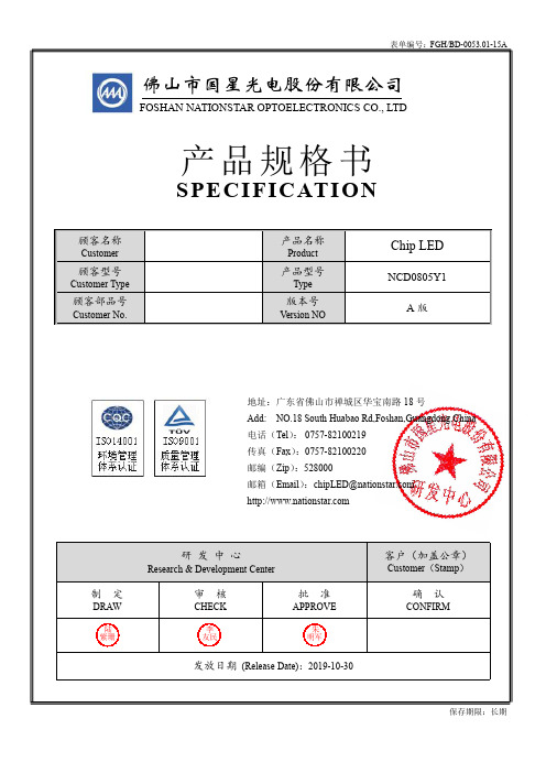
佛山市国星光电股份有限公司FOSHAN NATIONSTAR OPTOELECTRONICS CO.,LTD顾客名称Customer 产品名称ProductChip LED顾客型号Customer Type 产品型号TypeNCD0805Y1顾客部品号Customer No.版本号Version NOA版研发中心Research&Development Center客户(加盖公章)Customer(Stamp)制定DRAW 审核CHECK批准APPROVE确认CONFIRM陆紫珊李友民朱明军发放日期(Release Date):2019-10-30产品规格书地址:广东省佛山市禅城区华宝南路18号Add:NO.18South Huabao Rd,Foshan,Guangdong,China电话(Tel):*************传真(Fax):*************邮编(Zip):528000邮箱(Email):********************** SPECIFICATION保存期限:长期NCD0805Y1Chip Light Emitting Diode技术数据表Technical Data Sheet本产品主要作为信号指示及照明的电子元件广泛应用于各类使用表面贴装结构的电子产品中,如家用电器的开关指示灯、手机键盘灯、汽车仪表盘指示灯等。
This product is generally used as indicator and luminance for surface mounted electronic equipment,such as*The specifications of the product may be modified for improvement without notice.外形尺寸Outline Dimension极性Polarity-+推荐焊盘尺寸Recommended Soldering PadElectro-Optical Characteristics(1)✧极限参数(温度=25℃)Absolute Maximum Ratings(Temperature=25°C)*注:脉冲宽度≤0.1ms,占空比≤1/10*Note:Pulse Width≤0.1ms,Duty≤1/10✧光电参数(温度=25℃)Electro-Optical Characteristics(Temperature=25°C)*注1:光强偏差±15%;压降偏差±0.1V;(X,Y)坐标偏差±0.01;单色光波长偏差±1nm。
3mmled贴片导光柱90度折角平头导光柱

第一部分:介绍3mmled贴片导光柱90度折角平头导光柱在现代科技发展的大潮中,LED照明产品作为照明产业革新的主力军,备受关注。
而在LED照明产品中,3mmled贴片导光柱90度折角平头导光柱作为具有特殊作用的光电子元器件,正逐渐引起人们的兴趣。
1. 产生背景在LED照明产品中,光的导光效果对灯具的照明效果有着至关重要的影响。
为了提高LED照明产品的照明效果,3mmled贴片导光柱90度折角平头导光柱应运而生。
它能够较好地控制光的传播方向、减少能量损耗、提高光效,从而提升LED照明产品的照明亮度和均匀度。
2. 定义和特点3mmled贴片导光柱90度折角平头导光柱,是一种LED照明产品中常用的光学组件。
它具有90度折角、平头的特点,能够使LED的光线以柱状或矩形的形式均匀地导出,达到良好的光学效果。
这种导光柱具有优异的光学透射性能、高强度和耐高温的特点,可广泛应用于LED灯具、背光源、指示灯等产品中。
3. 作用和应用3mmled贴片导光柱90度折角平头导光柱在LED照明产品中发挥着重要的作用。
它能够使LED的光线均匀、温和地传播,减少光线的能量损失,在提高光效的还能提升LED产品的使用寿命。
目前,这种导光柱已经在户外景观照明、汽车照明、背光源等领域得到了广泛的应用,为LED照明产品的发展注入了新的活力。
以上是对3mmled贴片导光柱90度折角平头导光柱的简要介绍,接下来将深入探讨其在LED照明产品中的应用和未来发展趋势。
第二部分:3mmled贴片导光柱90度折角平头导光柱在LED照明产品中的应用1. 在户外景观照明中的应用在户外景观照明中,人们对照明效果的要求越来越高。
传统的照明产品往往难以满足这一需求,而引入了3mmled贴片导光柱90度折角平头导光柱后,可以通过其优异的光学性能,实现灯光的均匀、柔和传播,使得户外景观在夜晚展现出更加迷人的魅力。
这种导光柱在户外景观照明中得到了广泛的应用,并逐渐取代了传统的照明产品。
厦门凯莱光电技术有限公司 19-117 SMD LED 说明书

19-117/BHC-ZL1M2RY/3TFeatures․Package in 8mm tape on 7 diameter reel.․Compatible with automatic placement equipment.․Compatible with infrared and vapor phase reflow solder process.․Mono-color type.․Pb-free.․ESD Protection.․The product itself will remain within RoHS compliant version.Description․The 19-117SMD LED is much smaller than lead frame type components, thus enable smaller board size, higher packing density, reduced storage space and finally smaller equipment to be obtained.․Besides, lightweight makes them ideal for miniature applications. etc.Applications․Backlighting in dashboard and switch.․Telecommunication: indicator and backlighting in telephone and fax.․Flat backlight for LCD, switch and symbol.․General use.Device Selection GuideChipMaterialsEmitted Color Resin Color InGaN Blue Water Clear Absolute Maximum Ratings(Ta=25)Parameter Symbol Rating Unit Reverse Voltage V R5V Forward Current I F10mA eak Forward Current(Duty 1/10 @1KHz)I FP100mA Power Dissipation Pd40mW Electrostatic Discharge ESD HBM2000V Operating Temperature T opr-40 ~ +85 Storage Temperature Tstg-40 ~ +90Soldering Temperature Tsol Reflow Soldering : 260 for 10 sec. Hand Soldering : 350 for 3 sec.Electro-Optical Characteristics(Ta=25)Parameter Symbol Min.Typ.Max.Unit Condition LuminousIntensityIv11.5-----28.5mcdViewing Angle2θ1/2-----120-----degPeakWavelengthλp-----468-----nmDominantWavelengthλd465-----475nmSpectrumRadiationBandwidthλ-----25-----nmForward Voltage V F 2.50---- 3.10VI F=5mANote:1.Tolerance of Luminous Intensity: ±11%2.Tolerance of Dominant Wavelength ±1nm3. Tolerance of Forward Voltage: ±0.1VBin Range of Luminous IntensityBin Code Min.Max.Unit Condition L111.514.5L214.518.0mcd I F =5mA M118.022.5M222.528.5Bin Range Of Dom. WavelengthBin Code Min.Max.Unit Condition X465.0470.0nm I F =5mAY470.0475.0Bin Range Of Forward VoltageBin Code Min.Max.Unit Condition9 2.50 2.70V I F =5mA 10 2.70 2.9011 2.90 3.10Note:1.Tolerance of Luminous Intensity: ±11%2.Tolerance of Dominant Wavelength ±1nm3. Tolerance of Forward Voltage: ±0.1Typical Electro-Optical Characteristics CurvesPackage DimensionNote: Tolerances unless mentioned ±0.1mm. Unit = mmLabel Explanation‧CPN: Customer’s Product Number Array‧P/N: Product Number‧QTY: Packing Quantity‧CAT: Luminous Intensity Rank‧HUE: Chromaticity Coordinates & Dom. Wavelength Rank‧REF: Forward Voltage Rank‧LOT No: Lot NumberReel DimensionsNote: The tolerances unless mentioned is 0.1mm ,Unit = mmCarrier Tape Dimensions: Loaded quantity 3000 PCS per reelPrecautions For Use1. Over-current-proofCustomer must apply resistors for protection, otherwise slight voltage shift will cause bigcurrent change ( Burn out will happen ).2. Storage2.1Do not open moisture proof bag before the products are ready to use.2.2 Before opening the package: The LEDs should be kept at 30 or less and 90%RH or less.2.3 After opening the package:The LED's floor life is 1 year under 30 or less and 60% RH or less.If unused LEDs remain, it should be stored in moisture proof packages.2.4 If the moisture absorbent material (silica gel) has faded away or the LEDs have exceeded theBaking treatment : 603.3 When soldering, do not put stress on the LEDs during heating.3.4 After soldering, do not warp the circuit board.4.Soldering IronEach terminal is to go to the tip of soldering iron temperature less than 350 for 3 seconds within once in less than the soldering iron capacity 25W. Leave two seconds and more intervals, and do soldering of each terminal. Be careful because the damage of the product is often started at the time of the hand solder.5.RepairingRepair should not be done after the LEDs have been soldered. When repairing is unavoidable, a double-head soldering iron should be used (as below figure). It should be confirmed beforehand whether the characteristics of the LEDsApplication RestrictionsHigh reliability applications such as military/aerospace, automotive safety/security systems,and medical equipment may require different product. If you have any concerns, please contact Everlight before using this product in your application. This specification guarantees the quality and performance of the product as an individual component. Do not use this product beyond the specification described in this document.。
Tridonic LED产品质保条件说明书

2021质保条件2016质保条件未来几年的安全性和可靠性因修复缺陷(履行质保承诺)产生的附带成本,如安装和移除、缺陷产品和已维修产品或新品运输、处置、运行和转接时间、起重机、脚手架(这些成本由买方承担)。
易损件,如所有标准灯具(不包括 LED 模组)、电池(不包括应急电池);包含硬盘或机械易损件的计算机和服务器。
配件,如电缆、包覆层及用于电流调节的电阻器。
会因自然老化褪色或变脆的塑料件(例如,聚碳酸酯零件)。
Tridonic 用第三方标签作为商品出售的电子配件和产品,例如,触摸屏、IT 网络设备和计算机。
设备上根据磨损情况、疲劳程度或污渍变更的设置或参数设置。
因软件错误、漏洞、病毒等产生的产品缺陷。
不时需要的服务,例如,重新调试、软件更新等。
若客户或第三方未经质保人事先书面同意做出或实施变更、维修、服务工作或故障排除,本质保书立即失效。
关于 LED 产品的其他信息:LED 模组光通量数值降幅在0.6%/1,000 工作小时以内的,属于技术正常情况,因此不在制造商的质保书范围之内,在产品与使用规范(特别是参数表、规格书、产品手册等)中另有定义的除外。
LED 模组的允许色差不在制造商的质保书范围之内。
若为新 LED 模组,光通量和性能存在公差。
所有相关的技术数据见产品与使用规范(特别是参数表、规格书、产品手册等)。
若为后续交付的 LED 模组,由于技术进步以及因使用导致产品的光通量和光色发生变化,光学性能可能与原装产品不同。
本质保书条款并未排除、限制或变更客户的法定质保权利。
提供质保服务时,无论法律原因为何,Tridonic 都会按照质保生效时有效的一般销售与交付条件(附于发票或由客户向 Tridonic 索取)承担责任。
否则,我们将不承担任何损害赔偿责任。
本质保书符合奥地利法律,不包括联合国国际货物销售合同公约 (CISG) 的条款。
因本质保书产生的所有争议应提交至奥地利Feldkirch仲裁。
