052Safety device system by pass procedure
SMART GUARD 用户手册说明书
www.smart-hitech.eu 4004 Plovdiv 75A D. Talev StrUser Guide for working with the alarmsystem SMART GUARDTable of Contents:1.Working with keypad (2)1.1.Description of multifunctional buttons (3)1.2.Audible signals (4)2.ARM and DISARM (5)2.1.FULL ARM mode (5)2.2.STAY ARM mode (6)2.3.SLEEP ARM mode (7)2.4.DISARM (8)3.Quick user password change (8)4.Clearing alarm memory (9)5.Full memory log review (9)6.Bypassing zones (10)7.Resetting fire detectors (10)8.Doorbell notification (11)9.Keypad display cleaning mode (11)10.Smart Guard Control activation for remote control via mobile device or web browser (12)www.smart-hitech.eu 4004 Plovdiv 75A D. Talev StrGPS Systems Bulgaria has created hi-technology intruder alarm system that incorporates rich functionality and numerous technological solutions for home and office protection.The SMART GUARD alarm system combines all advantages of the traditional intruder alarms but even goes beyond them. It expands and improves all functionalities to a level of highly intelligent system for management and control.1.Working with keypadSG KEYPAD has stylish and elegant design with large two-line display. It is equipped with capacitive touch buttons and adjustable built-in LED backlight. An adjustable built-in buzzer can notify you for all system events. Via its intuitive and user-friendly designed menus, all system parameters can be setup locally. It will guide you through the settings with easy-to-understand messages. The built-in backlight under the multi-functional buttons will help you for quick navigation about the system state.Several predefined buttons are available for the most used actions. After each action, a corresponding message will appear on the keypad display.www.smart-hitech.eu 4004 Plovdiv 75A D. Talev Str1.1.Description of multifunctional buttonsNOTE 1: If there is no key touch for more than 1 minute, the system will logout the current user.NOTE 2: The keypad will lock for some time after 4 consecutive wrong passwords.1.2. Audible signalsThe keypad can alert for system events with different audible signals. The volume of those signals can be adjust or completely stopped.Event DescriptionButton touch Short beep.Confirm Short beep.Reject Long beep.Exit time Short beeps inform the user that there is a limited time to leave the area before arming. A few seconds before the time runs out, the beeps speed up.Entry time Short beeps inform the user that there is a limited time to enter its code and disarm the area. A few seconds before the time runs out, the beeps speed up.ARM / DISARM Three consecutive beeps, where the last islonger.Technical problem A single short beep and the dedicated indicatorstarts blinking.Doorbell zone triggering Short fading beeps informing the triggering of an "entry" zone (only in disarmed area).Fire alarm Repeating beeps informing the triggering of firezone.2.A RM and DISARM2.1.FULL ARM modeIn this mode, all zones from the selected area(s) will be monitor and alarm will generate if any of the zones is trigger. System is ready to arm only if all zones are closed and the ARM status indicator lights in green. Entering a valid user code and selecting desired area number from 1 to 8 will activate its FULL ARM mode.FULL ARMUser code FULL ARM Area number Exit timeArming will start by counting the exit time with audible signal (short beeps) and flashing the ARM status indicator in red. In the last few seconds, the beeps will speed up. Exit time will end with the ARM tone - three consecutive beeps, where the last is longer and the ARM status indicator lights steadily red.If the user has permissions for only one area, the system will skip asking for its number and will go directly to the exit time.www.smart-hitech.eu 4004 Plovdiv 75A D. Talev Str Arming all areas at once can be done with Quick FULL ARM by touching the 0 button for area number.Quick FULL ARM for all areasArming the system can be done with proximity (RFID) cards and tags. They can be used along with the user codes or instead of them. These cards have to be hold in front of the keypad reader in order to read them properly. They have to be configure in the system before use.2.2.STAY ARM modeThe STAY ARM mode differs from FULL ARM only in that it does not monitor all zones. These zones are disable for monitoring in this mode (bypassed). This means that the user can stay in the armed area without generate alarms. This mode is activate the same way like FULL ARM - after entering a valid user code or proximity card.www.smart-hitech.eu 4004 Plovdiv 75A D. Talev StrQuick STAY ARM is also available, but with different dedicated button.2.3.SLEEP ARM modeThe SLEEP ARM mode is the same as STAY ARM. The only difference is in the bypassed zones, which can be different. In this mode the user can “sleep” in the armed area without generate alarms. This mode is activate the same way like FULL and STAY ARM - after entering a valid user code or proximity card.Quick SLEEP ARM is also available, but with different dedicated button.www.smart-hitech.eu 4004 Plovdiv 75A D. Talev Str2.4.DISARMDisarming usually begins with the triggering of an entry zone. The keypad starts the entry time with audible signal (short beeps) and flashing the ARM status indicator in red. The system will wait for a valid user code or proximity card in order to disarm the area. If no valid code or card is applying until the entry time expires, an alarm will generate. After valid code or card is applied, the keypad will end the entry time with the DISARM tone - three consecutive beeps, where the last is longer and the ARM status indicator lights steadily green. A user can disarm areas only for which has permissions.DISARMEntrytime User code DISARMArea numberQuick DISARM for all areas0 Entrytime User code DISARM All areas 3.Q uick user password changeAny user password can be change quickly, by following these steps:1.Enter the current (old) user code;2.Hold OK button for 3 seconds;3.Enter the new user code;4.Confirm the new user code.4.C learing alarm memoryThe memory “LOG” button will light in red if any alarm occurred during the last armed period or if an alarm trigger in 24-hour zone while the area is disarm. There are two ways to clear this memory status – by viewing it or next time when arm the area it will clear automatically.To view (clear) the alarm memory, after entering the user code, the “LOG” button have to be pressed. The alarm events will appear on keypad’s display and can be scroll via the arrow buttons. The alarm buffer will clear and the red light will disappear from the “LOG” button after all events were scroll.5.F ull memory log reviewFull system memory log can be review via keypad. Permissions for this operation have only Master users and the Engineer. Accessing this option is after holding the “LOG” button for 3 seconds.6.B ypassing zonesEach user can temporary disable (bypass) one or more zones for being monitor after ARM. In order to do this, he has to have permissions for the corresponding area, in which the zones belong.7.R esetting fire detectorsIn many cases the alarm systems has conventional fire and smoke detectors connected to their zone loops. After triggering such detector, its power supply has to be cut off in order to reset its normal state. Usually this option is provide via one or few PGMs connected to detectors’ negative terminals. With such wiring, the user has the ability to “reset” their power supply after being triggered. This option is available in thewww.smart-hitech.eu 4004 Plovdiv 75A D. Talev Str8.D oorbell notificationThe doorbell notification is an audible signal sounded from the keypad to indicate that an entry zone has been trigger. This option can be quickly turn on or off for all zones from 1 to 9 by holding down the corresponding button number.Turning on/off the doorbell for the keypad’s internal zone is done by holding down the button number 0.9.K eypad display cleaning modeIn order to prevent unwanted key activation while cleaning display surface, the keypad can be set in a special cleaning mode with holding the “CANCEL” button for 5 seconds. When entering in this mode, all the buttons will be inactive for 1 minute. A message “CLEANING MODE” will display on the screen.www.smart-hitech.eu 4004 Plovdiv 75A D. Talev Str10.Smart Guard Control activation for remotecontrol via mobile device or web browserSmart Guard Control application can be download for iPhone and iPad devices from App Store or by scanning this QR code:For Android devices, the application can be download from Google Play or by scanning this QR code:For using via web browser, it can be access following this link: https://cloud.smart-hitech.eu/Activation steps:1)Start the Smart Guard Control application or log in to the followinglink: https://cloud.smart-hitech.eu/2)Create a new user (if you do not have registered one), followingthe steps in the application. You have to enter a valid e-mail;3)You will receive an e-mail with a confirmation link to complete theregistration;4)If you do not receive a confirmation email for a long time, checkyour email for spam or create a new one using the “forgottenwww.smart-hitech.eu 4004 Plovdiv 75A D. Talev Strpassword” option by entering the E-mail with which you made the registration in the “E-mail” field;5)After registration confirming, you can log in with your username(entered e-mail) and password;After successful login, you can add a new object. In order to do this, you will need:1.Each control panel serial number – it is located on the top of the panel’s PCB but you can find it from the keypad’s menu options. The SN of the panel is visible after entering a user code and is located in the menu "SN PANEL"Remember (save) the panel’s serial number.2.Cloud password (PIN)10. CLOUDPINPasswordaccepted Enter PIN Confirm newPINRemember (save) entered password for CLOUD PIN.www.smart-hitech.eu 4004 Plovdiv 75A D. Talev Str3.Cloud pairing code – can be generate by the Master or Engineer only!Remember (save) the activation code.ATTENTION:To make all this possible, you have to allow theconnection to the Cloud system into the control panel.Registering an object in the cloud https://cloud.smart-hitech.eu1.Enter your username in Smart Guard Control app.2.From the main window, select "Object register". Enter information in the "Device Serial Number" (enter SN Panel here) “Pairing code” (enter Activation code here) and “PIN” (enter PIN cloud here).3. Choose name and icon from the drop-down menu, with them the object will be display for you later in the cloud.4. Click "Save".。
S710D hboot 最简单的降级方法
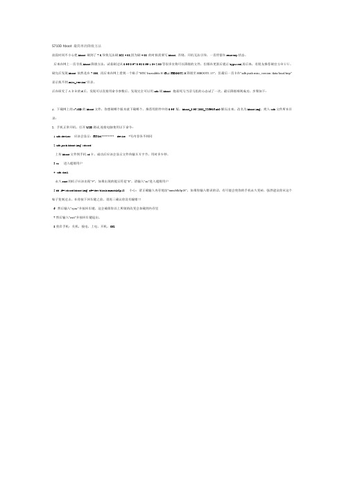
S710D hboot 最简单的降级方法前段时间不小心把hboot 刷到了7.0,导致无法刷ICS 4.08,因为刷4.08 的时候需要写hboot, 否则,开机无法引导,一直停留在recovery状态。
后来在网上一直寻找hboot降级方法,试着刷过从0.96/0.97/0.98/0.99/1.04/2.00等很多宣称可以降级的文件,但都在更新后提示bypassed,再后来,有朋友推荐刷官方RUU,刷完后发现hboot 依然是在7.000, 再后来在网上看到一个贴子“HTC Incredible S(G11)HBOOT2.0降级至HBOOT1.13”,但最后一直卡在“adb push misc_version /data/local/tmp” 显示找不到misc_version"目录。
后在研究了ADB的f后,发现可以直接用命令参数后,发现完全可以用adb刷hboot. 抱着死马当活马医的心态试了一次,最后降级顺利成功,步聚如下:1.下载网上的s710D的hboot文件,你想刷哪个版本就下载哪个,推荐用附件中的0.96 版,hboot_0.96.2000_336906.nb0解压出来,改名为hboot.img,拷入adb文件所在目录;2.手机正常开机,打开USB调试,连接电脑使用以下命令:1.adb devices 应该会显示:HT0A******** device *号内容各不相同2.adb push hboot.img /sdcard/上传hboot文件到手机sd卡,成功后应该会显示文件传输XX字节,用时多少秒。
3.su 进入超级用户4. adb shell永久root的机子应该出现“#”,如果出现的提示符是“$”,请输入“su”进入超级用户5.dd if=/sdcard/hboot.img of=/dev/block/mmcblk0p18 小心:请正确输入内存地址“mmcblk0p18”,如果你输入错误的话,有可能会使你的手机永久变砖,强烈建议你从这个帖子复制过去。
inaccessible boot device 的高级回答 -回复
inaccessible boot device 的高级回答-回复[Inaccessible Boot Device 的高级回答]Inaccessible Boot Device是一个出现在Windows操作系统中的常见错误。
它表明根据系统配置,Windows无法访问或读取启动设备的一部分。
当您遇到这个错误时,您将看到蓝屏并且系统无法启动。
在这篇文章中,我将带您逐步了解Inaccessible Boot Device错误并提供解决方案。
第一步:了解Inaccessible Boot Device错误Inaccessible Boot Device错误通常发生在以下情况下:1. 升级或安装了新的硬件设备。
2. 安装了新的驱动程序或更新了现有的驱动程序。
3. 引导配置文件发生了错误。
4. 损坏的硬盘驱动器或存储控制器。
第二步:重启并检查硬件连接首先,尝试重启您的计算机。
这可以解决某些临时的硬件连接问题。
确保硬盘连接线和电源线都连接牢固无误,并检查其他硬件设备(如RAM 条和显卡)是否正确安装。
第三步:排除驱动程序问题1. 如果您最近安装了新的硬件设备,请将其断开并重新启动计算机。
如果错误消失,那么问题可能是这个设备的驱动程序引起的。
在这种情况下,尝试更新或重新安装相关驱动程序。
2. 如果您最近安装了新的驱动程序或更新了现有驱动程序,请尝试进入安全模式。
在安全模式下,系统只加载必需的驱动程序,这可以帮助您确定是哪个驱动程序引起了问题。
在安全模式下,打开“设备管理器”并卸载最近更新的驱动程序。
第四步:修复引导配置文件1. 启动计算机并进入BIOS设置。
您可以按下计算机启动时显示的提示键打开BIOS设置页面。
2. 在BIOS设置中,找到“启动顺序”或“引导选项”。
确保硬盘是首选引导设备,并将其移动到列表的顶部。
3. 如果您在BIOS设置中找不到硬盘,请尝试重新连接硬盘或更换数据线。
4. 如果您使用的是UEFI引导模式,请尝试禁用安全引导功能。
Parker Hannifin Corporation Sporlan Division - P-S
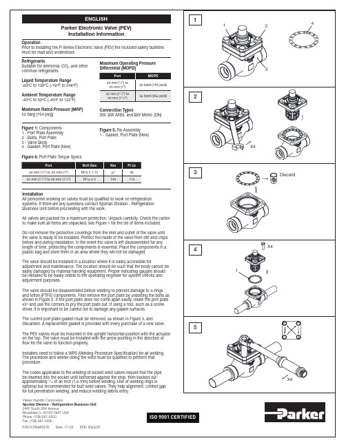
Parker Hannifin CorporationSporlan Division - Refrigeration Business Unit 2445 South 25th AvenueBroadview, IL 60155-3891 USA Phone: (708) 681-6300Fax: (708) 681-6306ISO 9001 CERTIFIED1234112341234X4X4X4Discard5OperationPrior to installing the P-Series Electronic Valve (PEV) the included safety bulletins must be read and understood.ENGLISHRefrigerantsSuitable for ammonia, CO 2, and other common refrigerantsLiquid Temperature Range -60ºC to 120ºC (-76ºF to 248ºF)Ambient Temperature Range -40ºC to 50ºC (-40ºF to 122ºF)Maximum Rated Pressure (MRP)52 barg (754 psig)Maximum Operating Pressure Differential (MOPD)Figure 1: Components 1 - Port Plate Assembly 2 - Bolts, Port Plate 3 - Valve Body4 - Gasket, Port Plate (New)PortBolt Size Nm Ft Lb 20 mm (3⁄4”) to 25 mm (1”)M12 x 1.75614532 mm (11⁄4”) to 40 mm (11⁄2”)M16 x 2149110Figure 5: Re-Assembly1 - Gasket, Port Plate (New)InstallationAll personnel working on valves must be qualified to work on refrigeration systems. If there are any questions contact Sporlan Division - Refrigeration Business Unit before proceeding with the work.All valves are packed for a maximum protection. Unpack carefully. Check the carton to make sure all items are unpacked, see Figure 1 for the list of items included. Do not remove the protective coverings from the inlet and outlet of the valve until the valve is ready to be installed. Protect the inside of the valve from dirt and chips before and during installation. In the event the valve is left disassembled for any length of time, protecting the components is essential. Place the components in a plastic bag and store them in an area where they will not be damaged.The valve should be installed in a location where it is easily accessible foradjustment and maintenance. The location should be such that the body cannot be easily damaged by material handing equipment. Proper indicating gauges should be installed to be easily visible to the operating engineer for system checks and adjustment purposes.The valve should be disassembled before welding to prevent damage to o-rings and teflon (PTFE) components. First remove the port plate by unbolting the bolts as shown in Figure 2. If the port plate does not come apart easily, rotate the port plate 45º and use the corners to pry the port plate out. If using a tool, such as a screw driver, it is important to be careful not to damage any gasket surfaces.The current port plate gasket must be removed, as shown in Figure 3, anddiscarded. A replacement gasket is provided with every purchase of a new valve.The PEV valves must be mounted in the upright horizontal position with the actuator on the top. The valve must be installed with the arrow pointing in the direction of flow for the valve to function properly.Installers need to follow a WPS (Welding Procedure Specification) for all welding. The procedure and welder doing the weld must be qualified to perform that procedure.The codes applicable to the welding of socket weld valves require that the pipe be inserted into the socket until bottomed against the stop, then backed out approximately 1⁄16 of an inch (1.6 mm) before welding. Use of welding rings isoptional but recommended for butt weld valves. They help alignment, control gap for full penetration welding, and reduce welding debris entry.Figure 6: Port Plate Torque SpecsPort MOPD 20 mm (3⁄4”) to 25 mm (1”)52 bard (754 psid)32 mm (11⁄4”) to 40 mm (11⁄2”)28 bard (406 psid)Connection TypesSW, BW ANSI, and BW Metric (DN)P/N 313906RSD B Date: 11-20 ECO: 0345229Parker Electronic Valve (PEV)Installation InformationWARNING – USER RESPONSIBILITY。
Indradrive 系列 故障代码
Error MessagesF9001 Error internal function call.F9002 Error internal RTOS function callF9003 WatchdogF9004 Hardware trapF8000 Fatal hardware errorF8010 Autom. commutation: Max. motion range when moving back F8011 Commutation offset could not be determinedF8012 Autom. commutation: Max. motion rangeF8013 Automatic commutation: Current too lowF8014 Automatic commutation: OvercurrentF8015 Automatic commutation: TimeoutF8016 Automatic commutation: Iteration without resultF8017 Automatic commutation: Incorrect commutation adjustment F8018 Device overtemperature shutdownF8022 Enc. 1: Enc. signals incorr. (can be cleared in ph. 2) F8023 Error mechanical link of encoder or motor connectionF8025 Overvoltage in power sectionF8027 Safe torque off while drive enabledF8028 Overcurrent in power sectionF8030 Safe stop 1 while drive enabledF8042 Encoder 2 error: Signal amplitude incorrectF8057 Device overload shutdownF8060 Overcurrent in power sectionF8064 Interruption of motor phaseF8067 Synchronization PWM-Timer wrongF8069 +/-15Volt DC errorF8070 +24Volt DC errorF8076 Error in error angle loopF8078 Speed loop error.F8079 Velocity limit value exceededF8091 Power section defectiveF8100 Error when initializing the parameter handlingF8102 Error when initializing power sectionF8118 Invalid power section/firmware combinationF8120 Invalid control section/firmware combinationF8122 Control section defectiveF8129 Incorrect optional module firmwareF8130 Firmware of option 2 of safety technology defectiveF8133 Error when checking interrupting circuitsF8134 SBS: Fatal errorF8135 SMD: Velocity exceededF8140 Fatal CCD error.F8201 Safety command for basic initialization incorrectF8203 Safety technology configuration parameter invalidF8813 Connection error mains chokeF8830 Power section errorF8838 Overcurrent external braking resistorF7010 Safely-limited increment exceededF7011 Safely-monitored position, exceeded in pos. DirectionF7012 Safely-monitored position, exceeded in neg. DirectionF7013 Safely-limited speed exceededF7020 Safe maximum speed exceededF7021 Safely-limited position exceededF7030 Position window Safe stop 2 exceededF7031 Incorrect direction of motionF7040 Validation error parameterized - effective thresholdF7041 Actual position value validation errorF7042 Validation error of safe operation modeF7043 Error of output stage interlockF7050 Time for stopping process exceeded8.3.15 F7051 Safely-monitored deceleration exceeded (159)8.4 Travel Range Errors (F6xxx) (161)8.4.1 Behavior in the Case of Travel Range Errors (161)8.4.2 F6010 PLC Runtime Error (162)8.4.3 F6024 Maximum braking time exceeded (163)8.4.4 F6028 Position limit value exceeded (overflow) (164)8.4.5 F6029 Positive position limit exceeded (164)8.4.6 F6030 Negative position limit exceeded (165)8.4.7 F6034 Emergency-Stop (166)8.4.8 F6042 Both travel range limit switches activated (167)8.4.9 F6043 Positive travel range limit switch activated (167)8.4.10 F6044 Negative travel range limit switch activated (168)8.4.11 F6140 CCD slave error (emergency halt) (169)8.5 Interface Errors (F4xxx) (169)8.5.1 Behavior in the Case of Interface Errors (169)8.5.2 F4001 Sync telegram failure (170)8.5.3 F4002 RTD telegram failure (171)8.5.4 F4003 Invalid communication phase shutdown (172)8.5.5 F4004 Error during phase progression (172)8.5.6 F4005 Error during phase regression (173)8.5.7 F4006 Phase switching without ready signal (173)8.5.8 F4009 Bus failure (173)8.5.9 F4012 Incorrect I/O length (175)8.5.10 F4016 PLC double real-time channel failure (176)8.5.11 F4017 S-III: Incorrect sequence during phase switch (176)8.5.12 F4034 Emergency-Stop (177)8.5.13 F4140 CCD communication error (178)8.6 Non-Fatal Safety Technology Errors (F3xxx) (178)8.6.1 Behavior in the Case of Non-Fatal Safety Technology Errors (178)8.6.2 F3111 Refer. missing when selecting safety related end pos (179)8.6.3 F3112 Safe reference missing (179)8.6.4 F3115 Brake check time interval exceeded (181)Troubleshooting Guide | Rexroth IndraDrive Electric Drivesand ControlsI Bosch Rexroth AG VII/XXIITable of ContentsPage8.6.5 F3116 Nominal load torque of holding system exceeded (182)8.6.6 F3117 Actual position values validation error (182)8.6.7 F3122 SBS: System error (183)8.6.8 F3123 SBS: Brake check missing (184)8.6.9 F3130 Error when checking input signals (185)8.6.10 F3131 Error when checking acknowledgment signal (185)8.6.11 F3132 Error when checking diagnostic output signal (186)8.6.12 F3133 Error when checking interrupting circuits (187)8.6.13 F3134 Dynamization time interval incorrect (188)8.6.14 F3135 Dynamization pulse width incorrect (189)8.6.15 F3140 Safety parameters validation error (192)8.6.16 F3141 Selection validation error (192)8.6.17 F3142 Activation time of enabling control exceeded (193)8.6.18 F3143 Safety command for clearing errors incorrect (194)8.6.19 F3144 Incorrect safety configuration (195)8.6.20 F3145 Error when unlocking the safety door (196)8.6.21 F3146 System error channel 2 (197)8.6.22 F3147 System error channel 1 (198)8.6.23 F3150 Safety command for system start incorrect (199)8.6.24 F3151 Safety command for system halt incorrect (200)8.6.25 F3152 Incorrect backup of safety technology data (201)8.6.26 F3160 Communication error of safe communication (202)8.7 Non-Fatal Errors (F2xxx) (202)8.7.1 Behavior in the Case of Non-Fatal Errors (202)8.7.2 F2002 Encoder assignment not allowed for synchronization (203)8.7.3 F2003 Motion step skipped (203)8.7.4 F2004 Error in MotionProfile (204)8.7.5 F2005 Cam table invalid (205)8.7.6 F2006 MMC was removed (206)8.7.7 F2007 Switching to non-initialized operation mode (206)8.7.8 F2008 RL The motor type has changed (207)8.7.9 F2009 PL Load parameter default values (208)8.7.10 F2010 Error when initializing digital I/O (-> S-0-0423) (209)8.7.11 F2011 PLC - Error no. 1 (210)8.7.12 F2012 PLC - Error no. 2 (210)8.7.13 F2013 PLC - Error no. 3 (211)8.7.14 F2014 PLC - Error no. 4 (211)8.7.15 F2018 Device overtemperature shutdown (211)8.7.16 F2019 Motor overtemperature shutdown (212)8.7.17 F2021 Motor temperature monitor defective (213)8.7.18 F2022 Device temperature monitor defective (214)8.7.19 F2025 Drive not ready for control (214)8.7.20 F2026 Undervoltage in power section (215)8.7.21 F2027 Excessive oscillation in DC bus (216)8.7.22 F2028 Excessive deviation (216)8.7.23 F2031 Encoder 1 error: Signal amplitude incorrect (217)VIII/XXII Bosch Rexroth AG | Electric Drivesand ControlsRexroth IndraDrive | Troubleshooting GuideTable of ContentsPage8.7.24 F2032 Validation error during commutation fine adjustment (217)8.7.25 F2033 External power supply X10 error (218)8.7.26 F2036 Excessive position feedback difference (219)8.7.27 F2037 Excessive position command difference (220)8.7.28 F2039 Maximum acceleration exceeded (220)8.7.29 F2040 Device overtemperature 2 shutdown (221)8.7.30 F2042 Encoder 2: Encoder signals incorrect (222)8.7.31 F2043 Measuring encoder: Encoder signals incorrect (222)8.7.32 F2044 External power supply X15 error (223)8.7.33 F2048 Low battery voltage (224)8.7.34 F2050 Overflow of target position preset memory (225)8.7.35 F2051 No sequential block in target position preset memory (225)8.7.36 F2053 Incr. encoder emulator: Pulse frequency too high (226)8.7.37 F2054 Incr. encoder emulator: Hardware error (226)8.7.38 F2055 External power supply dig. I/O error (227)8.7.39 F2057 Target position out of travel range (227)8.7.40 F2058 Internal overflow by positioning input (228)8.7.41 F2059 Incorrect command value direction when positioning (229)8.7.42 F2063 Internal overflow master axis generator (230)8.7.43 F2064 Incorrect cmd value direction master axis generator (230)8.7.44 F2067 Synchronization to master communication incorrect (231)8.7.45 F2068 Brake error (231)8.7.46 F2069 Error when releasing the motor holding brake (232)8.7.47 F2074 Actual pos. value 1 outside absolute encoder window (232)8.7.48 F2075 Actual pos. value 2 outside absolute encoder window (233)8.7.49 F2076 Actual pos. value 3 outside absolute encoder window (234)8.7.50 F2077 Current measurement trim wrong (235)8.7.51 F2086 Error supply module (236)8.7.52 F2087 Module group communication error (236)8.7.53 F2100 Incorrect access to command value memory (237)8.7.54 F2101 It was impossible to address MMC (237)8.7.55 F2102 It was impossible to address I2C memory (238)8.7.56 F2103 It was impossible to address EnDat memory (238)8.7.57 F2104 Commutation offset invalid (239)8.7.58 F2105 It was impossible to address Hiperface memory (239)8.7.59 F2110 Error in non-cyclical data communic. of power section (240)8.7.60 F2120 MMC: Defective or missing, replace (240)8.7.61 F2121 MMC: Incorrect data or file, create correctly (241)8.7.62 F2122 MMC: Incorrect IBF file, correct it (241)8.7.63 F2123 Retain data backup impossible (242)8.7.64 F2124 MMC: Saving too slowly, replace (243)8.7.65 F2130 Error comfort control panel (243)8.7.66 F2140 CCD slave error (243)8.7.67 F2150 MLD motion function block error (244)8.7.68 F2174 Loss of motor encoder reference (244)8.7.69 F2175 Loss of optional encoder reference (245)Troubleshooting Guide | Rexroth IndraDrive Electric Drivesand Controls| Bosch Rexroth AG IX/XXIITable of ContentsPage8.7.70 F2176 Loss of measuring encoder reference (246)8.7.71 F2177 Modulo limitation error of motor encoder (246)8.7.72 F2178 Modulo limitation error of optional encoder (247)8.7.73 F2179 Modulo limitation error of measuring encoder (247)8.7.74 F2190 Incorrect Ethernet configuration (248)8.7.75 F2260 Command current limit shutoff (249)8.7.76 F2270 Analog input 1 or 2, wire break (249)8.7.77 F2802 PLL is not synchronized (250)8.7.78 F2814 Undervoltage in mains (250)8.7.79 F2815 Overvoltage in mains (251)8.7.80 F2816 Softstart fault power supply unit (251)8.7.81 F2817 Overvoltage in power section (251)8.7.82 F2818 Phase failure (252)8.7.83 F2819 Mains failure (253)8.7.84 F2820 Braking resistor overload (253)8.7.85 F2821 Error in control of braking resistor (254)8.7.86 F2825 Switch-on threshold braking resistor too low (255)8.7.87 F2833 Ground fault in motor line (255)8.7.88 F2834 Contactor control error (256)8.7.89 F2835 Mains contactor wiring error (256)8.7.90 F2836 DC bus balancing monitor error (257)8.7.91 F2837 Contactor monitoring error (257)8.7.92 F2840 Error supply shutdown (257)8.7.93 F2860 Overcurrent in mains-side power section (258)8.7.94 F2890 Invalid device code (259)8.7.95 F2891 Incorrect interrupt timing (259)8.7.96 F2892 Hardware variant not supported (259)8.8 SERCOS Error Codes / Error Messages of Serial Communication (259)9 Warnings (Exxxx) (263)9.1 Fatal Warnings (E8xxx) (263)9.1.1 Behavior in the Case of Fatal Warnings (263)9.1.2 E8025 Overvoltage in power section (263)9.1.3 E8026 Undervoltage in power section (264)9.1.4 E8027 Safe torque off while drive enabled (265)9.1.5 E8028 Overcurrent in power section (265)9.1.6 E8029 Positive position limit exceeded (266)9.1.7 E8030 Negative position limit exceeded (267)9.1.8 E8034 Emergency-Stop (268)9.1.9 E8040 Torque/force actual value limit active (268)9.1.10 E8041 Current limit active (269)9.1.11 E8042 Both travel range limit switches activated (269)9.1.12 E8043 Positive travel range limit switch activated (270)9.1.13 E8044 Negative travel range limit switch activated (271)9.1.14 E8055 Motor overload, current limit active (271)9.1.15 E8057 Device overload, current limit active (272)X/XXII Bosch Rexroth AG | Electric Drivesand ControlsRexroth IndraDrive | Troubleshooting GuideTable of ContentsPage9.1.16 E8058 Drive system not ready for operation (273)9.1.17 E8260 Torque/force command value limit active (273)9.1.18 E8802 PLL is not synchronized (274)9.1.19 E8814 Undervoltage in mains (275)9.1.20 E8815 Overvoltage in mains (275)9.1.21 E8818 Phase failure (276)9.1.22 E8819 Mains failure (276)9.2 Warnings of Category E4xxx (277)9.2.1 E4001 Double MST failure shutdown (277)9.2.2 E4002 Double MDT failure shutdown (278)9.2.3 E4005 No command value input via master communication (279)9.2.4 E4007 SERCOS III: Consumer connection failed (280)9.2.5 E4008 Invalid addressing command value data container A (280)9.2.6 E4009 Invalid addressing actual value data container A (281)9.2.7 E4010 Slave not scanned or address 0 (281)9.2.8 E4012 Maximum number of CCD slaves exceeded (282)9.2.9 E4013 Incorrect CCD addressing (282)9.2.10 E4014 Incorrect phase switch of CCD slaves (283)9.3 Possible Warnings When Operating Safety Technology (E3xxx) (283)9.3.1 Behavior in Case a Safety Technology Warning Occurs (283)9.3.2 E3100 Error when checking input signals (284)9.3.3 E3101 Error when checking acknowledgment signal (284)9.3.4 E3102 Actual position values validation error (285)9.3.5 E3103 Dynamization failed (285)9.3.6 E3104 Safety parameters validation error (286)9.3.7 E3105 Validation error of safe operation mode (286)9.3.8 E3106 System error safety technology (287)9.3.9 E3107 Safe reference missing (287)9.3.10 E3108 Safely-monitored deceleration exceeded (288)9.3.11 E3110 Time interval of forced dynamization exceeded (289)9.3.12 E3115 Prewarning, end of brake check time interval (289)9.3.13 E3116 Nominal load torque of holding system reached (290)9.4 Non-Fatal Warnings (E2xxx) (290)9.4.1 Behavior in Case a Non-Fatal Warning Occurs (290)9.4.2 E2010 Position control with encoder 2 not possible (291)9.4.3 E2011 PLC - Warning no. 1 (291)9.4.4 E2012 PLC - Warning no. 2 (291)9.4.5 E2013 PLC - Warning no. 3 (292)9.4.6 E2014 PLC - Warning no. 4 (292)9.4.7 E2021 Motor temperature outside of measuring range (292)9.4.8 E2026 Undervoltage in power section (293)9.4.9 E2040 Device overtemperature 2 prewarning (294)9.4.10 E2047 Interpolation velocity = 0 (294)9.4.11 E2048 Interpolation acceleration = 0 (295)9.4.12 E2049 Positioning velocity >= limit value (296)9.4.13 E2050 Device overtemp. Prewarning (297)Troubleshooting Guide | Rexroth IndraDrive Electric Drivesand Controls| Bosch Rexroth AG XI/XXIITable of ContentsPage9.4.14 E2051 Motor overtemp. prewarning (298)9.4.15 E2053 Target position out of travel range (298)9.4.16 E2054 Not homed (300)9.4.17 E2055 Feedrate override S-0-0108 = 0 (300)9.4.18 E2056 Torque limit = 0 (301)9.4.19 E2058 Selected positioning block has not been programmed (302)9.4.20 E2059 Velocity command value limit active (302)9.4.21 E2061 Device overload prewarning (303)9.4.22 E2063 Velocity command value > limit value (304)9.4.23 E2064 Target position out of num. range (304)9.4.24 E2069 Holding brake torque too low (305)9.4.25 E2070 Acceleration limit active (306)9.4.26 E2074 Encoder 1: Encoder signals disturbed (306)9.4.27 E2075 Encoder 2: Encoder signals disturbed (307)9.4.28 E2076 Measuring encoder: Encoder signals disturbed (308)9.4.29 E2077 Absolute encoder monitoring, motor encoder (encoder alarm) (308)9.4.30 E2078 Absolute encoder monitoring, opt. encoder (encoder alarm) (309)9.4.31 E2079 Absolute enc. monitoring, measuring encoder (encoder alarm) (309)9.4.32 E2086 Prewarning supply module overload (310)9.4.33 E2092 Internal synchronization defective (310)9.4.34 E2100 Positioning velocity of master axis generator too high (311)9.4.35 E2101 Acceleration of master axis generator is zero (312)9.4.36 E2140 CCD error at node (312)9.4.37 E2270 Analog input 1 or 2, wire break (312)9.4.38 E2802 HW control of braking resistor (313)9.4.39 E2810 Drive system not ready for operation (314)9.4.40 E2814 Undervoltage in mains (314)9.4.41 E2816 Undervoltage in power section (314)9.4.42 E2818 Phase failure (315)9.4.43 E2819 Mains failure (315)9.4.44 E2820 Braking resistor overload prewarning (316)9.4.45 E2829 Not ready for power on (316)。
Kaspersky Security for Mobile 用户手册说明书

Kaspersky Security for Mobile © 2022 AO Kaspersky Lab目录Kaspersky Security for Mobile 帮助新增功能取决于管理工具的应用程序功能的比较分发包在 Kaspersky Security Center Web Console 和 Kaspersky Security Center 云控制台中工作关于 Kaspersky Security Center Web Console 和云控制台中的移动设备管理Kaspersky Security Center Web Console 和云控制台中的移动设备管理的主要功能关于 Kaspersky Endpoint Security for Android 应用程序关于 Kaspersky Security for Mobile 插件关于 Kaspersky Endpoint Security for Android 插件硬件和软件要求已知问题和注意事项在 Kaspersky Security Center Web Console 或云控制台中部署移动设备管理解决方案部署方案准备 Kaspersky Security Center Web Console 和云控制台以进行部署配置管理服务器以连接移动设备创建管理组创建自动将设备分配至管理组的规则部署管理插件从可用分发包列表安装管理插件从分发包安装管理插件部署 Kaspersky Endpoint Security for Android 应用程序使用 Kaspersky Security Center Web Console 或云控制台部署 Kaspersky Endpoint Security for Android 应用程序激活 Kaspersky Endpoint Security for Android 应用程序提供 Kaspersky Endpoint Security for Android 应用程序所需的权限管理证书查看证书列表定义证书设置创建证书续订证书删除证书与 Firebase Cloud Messaging 交换信息在 Kaspersky Security Center Web Console 和云控制台中管理移动设备将移动设备连接到 Kaspersky Security Center将未分配的移动设备移至管理组向移动设备发送命令从 Kaspersky Security Center 移除移动设备管理组策略用于管理移动设备的组策略查看组策略列表查看策略分发结果创建组策略修改组策略复制组策略将策略移动到另一个管理组删除组策略定义策略设置配置反病毒保护配置实时保护配置移动设备上的病毒扫描自动运行配置反病毒数据库更新定义设备解锁设置配置对被盗或丢失设备的数据的保护配置应用程序控制配置使移动设备符合公司安全要求的合规性控制启用和禁用合规性规则编辑合规性规则添加合规性规则删除合规性规则不合规标准列表不合规时的操作列表配置用户对网站的访问配置功能限制防止 Kaspersky Endpoint Security for Android 被删除配置移动设备与 Kaspersky Security Center 的同步卡巴斯基安全网络与卡巴斯基安全网络交换信息启用和禁用卡巴斯基安全网络与 Google Analytics for Firebase、SafetyNet Attestation、Firebase Performance Monitoring 和 Crashlytics 交换信息配置移动设备上的通知检测设备入侵(根权限)定义授权许可设置配置事件配置有关在用户设备上安装、更新和删除应用程序的事件网络负载在基于 MMC 的管理控制台中工作关键用例关于 Kaspersky Security for Mobile基于 MMC 的管理控制台中的移动设备管理的主要功能关于 Kaspersky Endpoint Security for Android关于 Kaspersky Device Management for iOS关于 Exchange 邮箱关于 Kaspersky Endpoint Security for Android 管理插件关于 Kaspersky Device Management for iOS 管理插件硬件和软件要求已知问题和注意事项部署解决方案架构常见集成解决方案部署方案Kaspersky Endpoint Security for Android 的部署方案iOS MDM 配置文件的部署方案准备管理控制台以便部署集成解决方案配置连接移动设备的管理服务器设置在管理控制台中显示“移动设备管理”文件夹创建管理组为设备自动分配至管理组创建规则创建常规证书安装 Kaspersky Endpoint Security for Android权限使用 Google Play 链接安装 Kaspersky Endpoint Security for Android Kaspersky Endpoint Security for Android 的其他安装方法从 Google Play 或华为应用市场手动安装创建和配置安装包创建独立安装包配置同步设置激活 Kaspersky Endpoint Security for Android 应用程序安装 iOS MDM 配置文件关于 iOS 设备管理模式通过 Kaspersky Security Center 安装安装管理插件更新先前版本的应用程序升级先前版本的 Kaspersky Endpoint Security for Android安装先前版本的 Kaspersky Endpoint Security for Android升级先前版本的管理插件删除 Kaspersky Endpoint Security for Android远程删除应用程序允许用户删除应用程序由用户删除应用程序配置和管理开始使用启动和停止应用程序创建管理组用于管理移动设备的组策略创建组策略配置同步设置管理对组策略的修订删除组策略限制配置组策略的权限保护在安卓设备上配置防病毒保护在互联网上保护 Android 设备保护被盗或丢失设备的数据向移动设备发送命令解锁移动设备数据加密配置设备解锁密码强度为安卓设备配置强解锁密码为 iOS MDM 设备配置强解锁密码为 EAS 设备配置强解锁密码配置虚拟专用网 (VPN)在安卓设备上配置 VPN(仅限三星)在 iOS MDM 设备上配置 VPN在安卓设备上配置防火墙(仅限三星)防止 Kaspersky Endpoint Security for Android 被删除检测设备入侵(根权限)在 iOS MDM 设备上配置全局 HTTP 代理向 iOS MDM 设备添加安全证书向 iOS MDM 设备添加 SCEP 配置文件控制配置限制运行 Android 10 及更高版本的设备的特殊注意事项配置安卓设备的限制配置 iOS MDM 设备功能限制配置 EAS 设备功能限制配置用户对网站的访问在安卓设备上配置网站访问在 iOS MDM 设备上配置网站访问使用公司安全要求控制安卓设备的合规性应用程序启动控制安卓设备上的应用程序启动控制为应用程序配置 EAS 设备限制安卓设备上的软件清单在 Kaspersky Security Center 中配置安卓设备的显示管理配置与 Wi-Fi 网络的连接将安卓设备连接至 Wi-Fi 网络将 iOS MDM 设备连接至 Wi-Fi 网络配置电子邮件在 iOS MDM 设备上配置邮箱在 iOS MDM 设备上配置 Exchange 邮箱在安卓设备上配置 Exchange 邮箱(仅限三星)管理第三方移动应用程序配置 Kaspersky Endpoint Security for Android 的通知将 iOS MDM 设备连接到 AirPlay将 iOS MDM 设备连接到 AirPrint配置访问点名称 (APN)在安卓设备上配置 APN(仅限三星)在 iOS MDM 设备上配置 APN配置安卓工作配置文件关于安卓工作配置文件配置工作配置文件添加 LDAP 帐户添加日历帐户添加联系人帐户配置日历订阅添加网络收藏夹添加字体使用第三方 EMM 系统管理应用程序(仅限 Android)开始使用如何安装应用程序如何激活应用程序如何连接设备到 Kaspersky Security CenterAppCon g 文件网络负载加入卡巴斯基安全网络与卡巴斯基安全网络交换信息启用和禁用使用卡巴斯基安全网络使用卡巴斯基私有安全网络对第三方服务的数据提供与 Firebase Cloud Messaging 交换信息与 Google Analytics for Firebase、SafetyNet Attestation、Firebase Performance Monitoring 和 Crashlytics 交换信息全局接受附加声明三星 KNOX通过 KNOX Mobile Enrollment 安装 Kaspersky Endpoint Security for Android 应用程序创建 KNOX MDM 配置文件在 KNOX Mobile Enrollment 中添加设备安装应用程序配置 KNOX 容器关于 KNOX 容器激活 Samsung KNOX在 KNOX 中配置防火墙在 KNOX 中配置 Exchange 邮箱附录配置组策略的权限应用程序类别使用 Kaspersky Endpoint Security for Android 应用程序程序功能主界面概览设备扫描运行计划扫描更改保护模式反病毒数据库更新计划的数据库更新设备丢失或被盗时如何操作Web 保护应用程序控制获取证书与 Kaspersky Security Center 同步不使用 Kaspersky Security Center 激活 Kaspersky Endpoint Security for Android 应用程序更新应用程序卸载应用程序带有手提箱图标的应用程序KNOX 应用程序程序授权许可关于最终用户许可协议关于授权许可关于订阅关于密钥数据提供联系技术支持如何获得技术支持通过“Kaspersky CompanyAccount”获得技术支持有关应用程序的其他信息源术语Apple 推送通知服务 (APNs) 证书EAS 设备Exchange Mobile Devices ServerIMAPiOS MDM 服务器iOS MDM 设备iOS MDM 配置文件Kaspersky Security Center Web Server Kaspersky Security Center 管理员Kaspersky 更新服务器Kaspersky 类别POP3SSL代理服务器供给配置文件最终用户授权许可协议卡巴斯基安全网络 (KSN)卡巴斯基私有安全网络(私有 KSN)反病毒数据库合规性控制安卓工作配置文件安装包密钥文件应用程序管理插件授权许可授权许可的有效期清单文件激活码激活程序独立安装包病毒监控设备策略管理员工作站管理服务器管理组组任务网络钓鱼解锁码订阅隔离有关第三方代码的信息商标声明Kaspersky Security for Mobile 帮助Kaspersky Security for Mobile 旨在保护和管理公司移动设备以及公司员工用于公司用途的个人移动设备。
DELL小主机设置篇-高级功能(史上最全)
高级功能Dell™ OptiPlex™ GX620用户指南LegacySelect 技术控制可管理性安全保护密码保护系统设置程序引导至USB 设备清除已忘记的密码清除CMOS 设置超线程电源管理LegacySelect 技术控制LegacySelect 技术控制可以基于通用平台、硬盘驱动器映像和帮助桌面程序提供完全使用、部分使用或不使用传统功能的解决方案。
管理员可以通过系统设置程序、Dell OpenManage™ IT Assistant 或Dell 工厂集成服务进行控制。
LegacySelect 使管理员可以通过电子方式激活或取消激活连接器和介质设备(包括串行和USB 连接器、并行连接器、软盘驱动器、PCI 插槽和PS/2 鼠标)。
取消激活连接器和介质设备后,便可以使用资源。
您必须重新启动计算机才能使更改生效。
可管理性警报标准格式ASF 是一种DMTF 管理标准,用于规定―预操作系统‖或―无操作系统‖的警报技术。
它可以在操作系统处于睡眠模式或系统关机时生成有关潜在安全问题和故障状态的警报。
ASF 是专为替代先前的无操作系统警报技术而设计的。
您的计算机支持以下ASF 1.03 版及 2.0 版警报和远程功能:ASF 用户指南和ASF 管理员指南。
Dell OpenManage™ IT AssistantIT Assistant 可以配置、管理和监测公司网络上的计算机及其它设备,并可以为配备行业标准管理软件的计算机管理资产、配置、事件(警报)和安全保护。
它支持符合SNMP、DMI 和CIM 行业标准的工具。
Dell OpenManage Client Instrumentation 基于DMI 和CIM,可用于您的计算机。
有关IT Assistant 的信息,请参阅Dell 支持Web 站点 上的Dell OpenManage IT Assistant 用户指南。
Dell OpenManage Client InstrumentationDell OpenManage Client Instrumentation 软件可以使远程管理程序(例如IT Assistant)执行以下操作:查看计算机信息,例如计算机处理器的数量以及计算机运行的操作系统。
海德博格控制器故障代码大全
海德博格控制器故障代码大全
海德博格控制器故障代码大全:
1-1xx错误:配置信息错误/参数超出范围
101 –主板非法/未连接
102 –程序存储器错误
103 –启动文件错误
104 – EEPROM 与实体设备不兼容
105 – EEPROM 中的错误
106 –错误的模式
107 –无效的程序存储器
108 –电路保护系统
109 –电流设置不匹配
110 –功能错误,或者参数超出范围
111 –开关量超出范围
112 –温度设定超出范围
113 –脉冲输入失效
114 –脉冲输出失效
2-1xx错误:参数校准错误
201 –无效的元件类型设定
202 –输出电流偏差
203 –输出转矩偏差
204 –电机转速偏差
205 –无效的速度设定
206 –无效的转矩设定
207 –无效的目标转速
3-1xx错误:硬件问题
301 –电机短路
302 –电机断路
303 –电机过流
304 –电源短路
305 –电源断路
306 –温度传感器短路307 –温度传感器断路308 –驱动器故障
309 –电机拖曳失效310 –电机过热
311 –冷却风扇故障312 –供电不足
313 –通信故障
314 –驱动模块故障315 –检测到系统故障。
macfee报警代码
mcafee8.5i全部报警提示代码及意思:1024 发现感染病毒的文件1025 已成功清除文件感染的病毒1026 无法清除文件中感染的病毒1027 感染病毒的文件已删除1028 无法删除感染病毒的文件1029 要从扫描中排除的文件1030 无法从扫描中排除项目1031 拒绝访问感染病毒的文件1032 感染病毒的文件已被移到隔离文件夹1033 无法将感染病毒的文件移动到隔离文件夹1034 扫描已完成未发现病毒1035 扫描被取消1036 内存已感染病毒1037 发现感染病毒的引导记录1038 扫描发现感染病毒的文件1039 扫描发现感染病毒的文件并已清除病毒1040 活动日志错误1041 扫描报告内存分配错误1042 路径太长1043 介质有写保护1044 找不到指定的介质1045 指定的扫描项目无效1046 文件 I/O 错误1047 磁盘 I/O 错误1048 扫描报告常规系统错误1049 扫描报告内部系统错误1050 无法修复受密码保护的项目1051 无法扫描受密码保护的项目1052 感染病毒的捆绑对象1053 发现感染病毒的文件1054 感染病毒的文件已删除1055 无法删除感染病毒的文件1056 文件已移动到隔离文件夹1057 无法将感染病毒的文件移动到隔离文件夹1059 扫描超时1060 引导区病毒已清除1061 清除引导区病毒时出错1062 发送警报时出错1063 指定的选项无效1064 服务已启动1065 服务已结束1066 任务成功启动1067 无法启动计划的任务1068 计划的任务已停止1069 停止计划的任务时出错1070 任务成功完成1071 任务已取消1076 记录信息时出错1077 内存分配错误1086 扫描进程错误1087 按访问扫描已启动1088 按访问扫描已停止1089 扫描设置1090 OAS 已停止1091 已阻止脚本运行1092 已被行为阻挡规则阻挡1093 已被缓冲区溢出保护阻挡1094 已被端口阻挡规则阻挡1095 将被行为阻挡规则阻挡1099 将被缓冲区溢出保护阻挡1100 在文件中检测到宏1101 已从文件中删除宏1118 更新成功完成1119 更新失败:请参阅事件日志1120 正在更新1121 更新已取消1122 正在升级1123 升级失败,参阅事件日志1124 升级已取消1125 DAT 版本不够新1126 扫描任务被 DAT 文件的自动更新而取消1127 OAS 扫描引擎已禁用1128 扫描超时1129 扫描任务被 WINDOWS 关闭1200 进程已启动1201 进程已结束1202 按需扫描已启动1203 按需扫描完成1204 报告操作系统序列号1270 病毒已隔离,没有清除程序1271 病毒已隔离,启发式扫描1272 病毒已隔离,不能清除1273 病毒已隔离,已加密1274 病毒未清除或隔离1275 病毒,启发式扫描,隔离失败1276 病毒,清除错误,隔离失败1277 病毒,已加密,隔离失败1278 病毒,没有清除程序,已删除1279 病毒,启发式扫描,没有清除程序,已删除1280 病毒,清除错误,已删除1281 病毒,已加密,已删除1282 病毒,没有清除程序,删除失败1283 病毒,启发式扫描,删除失败1284 病毒,清除错误,删除失败1285 病毒,已加密,删除失败1286 病毒,没有清除程序,已继续1287 病毒,启发式扫描,已继续1288 病毒,清除错误,已继续1289 病毒,已加密,已继续1290 病毒,没有清除程序,拒绝访问1291 病毒,启发式扫描,拒绝访问1292 病毒,清除错误,已拒绝访问1293 病毒,隔离失败,已删除1294 病毒,隔离失败,删除失败1295 病毒,隔离失败,已继续1296 病毒,隔离失败,已拒绝访问1297 病毒,删除失败,已隔离1298 病毒,删除失败,隔离失败1299 病毒,删除失败,已继续1300 病毒,删除失败,已拒绝访问1401 用户检测1402 用户清除和移动失败1403 用户检测已移动1404 用户清除和删除失败1405 用户检测已删除1406 用户检测已移动1407 用户移动和删除失败1408 用户检测已删除1409 用户检测移动失败1410 用户检测已删除1411 用户删除和移动失败1412 用户检测已移动1413 用户检测删除失败1500 已清除电子邮件感染的病毒1501 感染病毒的电子邮件已隔离1502 无法清除邮件中感染的病毒1503 检测到感染病毒的电子邮件1504 感染病毒的邮件项目已删除1505 电子邮件内容已过滤1506 电子邮件内容已阻挡1507 入站邮件因磁盘空间不足而挂起1508 入站邮件已恢复1509 启动请求处理成功1510 关闭请求处理成功1511 警告 - 异常终止1512 出现最大负载的情况1513 邮件病毒已隔离和清除1514 邮件病毒已隔离[未清除]1700 服务已成功启动1701 服务已成功结束1702 文件已阻挡1703 发现感染病毒的邮件正文1704 邮件被主题行扫描阻挡1705 发现感染病毒的文件1712 出现内部错误1713 按需扫描已启动1714 按需扫描已完成1715 防病毒引擎已停止1716 防病毒引擎已启动1719 无更新可用1721 磁盘空间不足1722 发现感染病毒的文件1725 产品即将达到使用寿命1726 引擎即将达到使用寿命1727 产品已超过支持期限1728 引擎已超过支持期限1729 已超过产品使用寿命1730 已超过引擎使用寿命1800 任务已成功启动1801 启动任务时出错1802 任务已完成1803 停止任务时出错1804 已发现并清除文件病毒1805 感染病毒的文件已成功隔离1806 感染病毒的文件已删除1807 感染病毒的文件已忽略。
宝马发动机系统防盗解除方法
寶馬轎車發動機防盜系統解除方法寶馬轎車發動機裝有電腦控制的防盜系統,一旦斷電,防盜系統將鎖死,使發動機無法啟動,只有安下列操作方法,才能解除。
1〃如手中有防盜密碼,可以按“XODE”後,將密碼輸入,再按“RESET”鍵即可解除。
2〃如果沒有正確密碼,切不可按動任何按鍵,或是再次啟動發動機。
3〃拆下蓄電池負極,等5—15秒後,再接好。
4〃將鑰匙打到“ON”位置,不要啟動發動機。
此時,報警器會響15秒,表示防盜系統以啟動,儀錶盤上顯示幕幕會出現“倒數15分鐘”的數字。
5〃15分鐘後,顯示幕幕出現0000字樣時,表示防盜系統已經被解除。
寶馬車身防盜系統解除大多數配有路程電腦的寶馬轎車均設有車身防盜系統。
當司機離開時,只要輸入自己設置的密碼,就可有效的防止被盜。
1、防盜系統的設置如圖,將鑰匙門置於第“1”位置段,用0—9叼之間的鍵輸入選定密碼。
如1234等從“0000至9999”之間的任一數字,按下“SET”鍵,將鑰匙門關至“0”位即可。
2、防盜系統的解除A、將鑰匙門開關置於“1”或“2”位置段,即ACC或ON;B、螢幕上出現“CODE”——;C、輸入正確密碼;D、按下“SET”鍵;如果三次輸入錯誤密碼,或三次在末輸入密碼狀態下試圖啟動轎車,報警器將會鳴叫30秒鐘。
如果原先設置的密碼遺忘,按下列步驟解除防盜系統;A、斷開電瓶,約等2秒鐘再接上,報警器鳴叫;B、打開鑰匙門於位置“1”;C、螢幕上顯示倒計時10分鐘;D、 10分鐘後,即可啟動發動機。
新款寶馬轎車防盜系統解除程式1、拆下電瓶線,再裝回。
2、打開駕駛側車門,將點火開關轉到ⅠⅠ段(R或15)位置。
等待15分鐘後,即自動解除防盜密碼。
3、寶馬原廠配置遙控器之車輛,則只要按下UNLOCK鍵,或利用鑰匙從駕駛側打開車門即自動防盜。
4、如果因(OB)旅程電腦故障,造成防盜鎖死,則可直接從(DME)引擎電腦剪掉防盜線路也可永久解除,DME55PIN電腦的38號腳,DME88PIN電腦的81號腳7系統6缸、8缸、88PIN電腦的6號。
诺基亚智能手机使用指南说明书
C
Capacities Chart .................... 344, 346 Carbon Monoxide Hazard .............. 52 Carrying Cargo .............................. 202 Cassette Player
Charging System Indicator .... 58, 328 Checklist, Before Driving............. 206 Child Safety ...................................... 20 Child Seats........................................ 25
Before Driving ............................... 191 Belts, Seat ..................................... 8, 41 Beverage Holder............................ 101 Body Repair .................................... 310
Maintenance............................... 279 Usage .................................. 111, 117 Air Outlets (Vents)................ 110, 115 Air Pressure, Tires ........................ 282 Alcohol in Gasoline........................ 350 Aluminum Wheels, Cleaning........ 305 Antifreeze ....................................... 253 Anti-lock Brakes (ABS) Indicator................................ 59, 219 Operation .................................... 218 Anti-theft, Audio System............... 179 Anti-theft Steering Column Lock .. 76
整理过的最全爱立信故障代码
1.3.3 SO CF,内部错误映射级别1A表 3 SO CF I1A故障编号------------------------ SO CF I1A: 1故障名称 重启,加电具体描述 关闭电源后,DXU 已经重新恢复。
注重: 只是提示信息,不是故障。
故障编号------------------------ SO CF I1A:2故障名称 重启,切换具体描述 已经使用DXU 重启按钮或OMT,重启DXU。
注重: 只是提示信息,不是故障。
11表 3 SO CF I1A故障编号------------------------ SO CF I1A:3故障名称 看门狗(Watchdog)重启具体描述 DXU已经发生重启。
可能原因 也许是软件出错。
操作 根据以下说明排除故障:􀁺 使用OMT 读取RBS 日志,并向爱立信发送故障报告,以进行修改;􀁺 假如故障频繁发生,则替换RBS 软件。
故障编号------------------------ SO CF I1A:4故障名称 软件故障重启具体描述 DXU已经进行重启。
可能原因 软件出现故障操作 根据以下说明排除故障:􀁺 使用OMT 读取RBS 日志,并向爱立信发送故障报告,以进行修改;􀁺 假如故障频繁发生,则替换RBS 软件。
故障编号------------------------ SO CF I1A:5故障名称 RAM故障重启具体描述 RDXU 已经进行重启。
操作 根据以下说明排除故障:􀁺 假如故障频繁发生,则替换RBS 软件,参见《维修手册》“RBS 现场维修”章节的“RBS 软件升级部分”;􀁺 替换DXU,参见《维修手册》“RBS 现场维修”章节的“DXU 替换”部分。
故障编号------------------------ SO CF I1A:6故障名称 重启,内部功能修改具体描述 DXU已经进行重启注重: 只是提示信息,不是故障。
IBM错误代码解释以及解决方法
IBM错误代码解释以及解决方法IBM的ThinkPad系列笔记本电脑的错误代码解释以及解决方法,希望能对拥有此款“本本”的朋友们有所帮助。
101:中断失败102:时钟失败103:时间中断失败104:保护模式失败105:最后的 8042命令未接受107:NMI 检测失败108:时钟总线检测失败109:Low meg芯片选择检测以上出错部件及解决措施:请检查主板设置是否正确,严重时需要更换主板。
110:平面奇偶出错部件及解决措施:这种情况一般是内存发生问题,请将内存换一个插槽试试。
不过,如果有连接到电脑的扩展部件,请先移除。
111:I/O奇偶出错部件及解决措施:仍然是首先检查内存条是否损坏,然后请检查扩展部件或端口复制器是否损坏。
0175:CRC1错,EEPROM校验错出错部件及解决措施:系统主板,停止POST任务。
1101: A类设备检测失败出错部件及解决措施:重点检查串口设备、通讯接线等部件。
1201: B类设备检测失败出错部件及解决措施:请检查主板上的红外接口是否损坏。
158:设置了SuperVisor密码但没有设置硬盘密码出错部件及解决措施:请重新设置硬盘密码159:硬盘密码与SuperVisor密码不相同出错部件及解决措施:请将硬盘的密码设置为与SuperVisor密码相同。
161:电池失效。
出错部件及解决措施:这当然是电池的问题,请重新更换电池或检查主板上的现用电池是否有漏电现象。
163:时间和日期未设置出错部件及解决措施:重新设置时间和日期。
173:设备数据丢失出错部件及解决措施:在屏幕上选择OK,然后设置时间和日期,必要时需要更换备用电池。
174:设置错误。
出错部件及解决措施:先去检查一下硬件设备是否配置正确,或者检查硬盘的跳线是否设置正确。
0177: SuperVisor密码检验错出错部件及解决措施:系统主板。
1701:硬盘控制器失败1780, 1790:硬盘0出错1781, 1791:硬盘1出错173 192 163出错,出错部件及解决措施:硬盘错误,当然也不排除主板存在错误。
Agilent E5052A 信号源分析仪数据手册说明书
1981AgilentE5052A Signal Source Analyzer10 MHz to 7, 26.5, or 110 GHzData SheetDefinitionsAll specifications apply over a 18 °C to 28 °C range (unless otherwise stated) and 30 minutes afterthe instrument has been turned on. All specified and supplemental values for RF input signals are applicable to sinusoidal-wave carriers unless otherwise noted.Supplemental information is intended to provide information that is helpful for using the instrument but that is not guaranteed by the product warranty. This information is denoted as either typical or nominal.Specification (spec.): Warranted performance. Specifications include guardbands to account for the expected statistical performance distribution, measurement uncertainties, and changes in performance due to environmental conditions.Typical (typ.): Expected performance of an average unit that does not include guardbands. It is not guaranteed by the product warranty.Nominal (nom.): A general, descriptive term that does not imply a level of performance. It is not guaranteed by the product warranty.24Figure1-4. SSB phase noise sensitivity of different LO optimization(typical)( standard, correlation = 1, carrier frequency = 1 GHz, startoffset frequency = 1 Hz, +5 dBm input, measurement time = 17.7 sec) Figure1-2. SSB phase noise sensitivity (E5052A-011, typical)(standard, < 150 kHz optim., +5 dBm input, start offset frequency= 10 Hz, measurement time = 4.4 sec)Figure1-3. SSB phase noise sensitivity improved with the cross-correlation function (typical) (standard, improvement with thecorrelation, carrier frequency = 1 GHz, < 150 kHz optim., +5 dBm input) Figure1-1. SSB phase noise sensitivity (typical)(standard, < 150 kHz optim., correlation = 1, +5 dBm input,start offset frequency = 1 Hz, measurement time = 17.7 sec)53. When a DUT’s frequency is settled to a selected target frequency.6Table 1-15. Narrow band transient (frequency bandwidth = 3.125 kHz)Measurement time (sec)100 m200 m500 m12510Frequency resolution (Hz rms)0.00950.00950.00340.00120.00040.00040.0004Time resolution (µsec)81.92163.84409.6819.21638.4409610240Number of point122212221222122212221222978Table 1-16. Narrow band transient (frequency bandwidth = 25 kHz)Measurement time (sec)10 m20 m50 m100 m200 m500 m12510 Frequency resolution (Hz rms)0.220.220.0760.0270.00950.00950.00950.00950.00950.0095 Time resolution (µsec)10.2420.4851.2102.4204.851212802560640012800 Number of point978978978978978978783783783783Table1-17. Narrow band transient (frequency bandwidth = 200 kHz)Measurement time (sec) 1 m 2 m 5 m10 m20 m50 m100 m200 m500 m12510 Frequency resolution (Hz rms) 4.9 4.9 1.70.60.20.20.20.20.20.20.20.20.2 Time resolution (µsec) 1.28 2.56 6.412.825.66416032080016003200800016000 Number of point783783783783783783626626626626626626626Table1-18. Narrow band transient (frequency bandwidth = 1.6 MHz)Measurement time (sec)100 µ200 µ500 µ 1 m 2 m 5 m10 m20 m50 m100 m200 m500 m12510 Frequency resolution (Hz rms)1101101103921145555555555 Time resolution (µsec)0.160.320.80.8 1.64820801603208001600320080001600 Number of point62662662612511251125112511001626626626626626626626626Table1-19. Narrow band transient (frequency bandwidth = 25.6 MHz)Measurement time (sec)10µ20µ50µ100µ200µ500µ 1 m 2 m 5 m10 m20 m50 m100 m200 m500 m125 Frequency resolution (Hz rms)7 k7 k7 k7 k 3 k884313313313313313313313313313313312.5312.5 Time resolution (µsec)0.010.020.050.10.20.512 6.2512.52562.5125250625125025006250 Number of point10011001100110011001100110011001801801801801801801801801801801Table 20. Spectrum monitor measurement capabilitiesSpectrum monitorNumber of trace 1 data trace and 1 memory trace per measurement traceData formats dBm, dBV, watt, volt, dBm / Hz, dBV / Hz, watt / Hz, volt / √HzMeasurement trigger Set to continuous, hold, or single, sweep with internal, external, manual, or bus trigger7Table 1-26. EMC and safetyDescription Supplemental informationEMC•European council directive 89 / 336 /EEC, 92 / 31 / EEC, 93 / 68 / EECIEC 61326 - 1: 1997 +A1: 1998 +A2:2000/EN 61326 - 1: 1997 +A1: 1998+A2: 2001•CISPR 11: 1997 +A1: 1999 / EN 55011:1998 +A1: 1999•Group 1, Class A•IEC 61000 - 4-2:1995 +A1: 1998 / EN61000 - 4-2: 1995 +A1: 1998• 4 kV CD / 8 kV AD•IEC 61000 - 4-3: 1995 +A1: 1998 / EN61000 - 4-3: 1996 +A1: 1998• 3 V / m, 80 - 1000 MHz, 80% AM•IEC 61000 - 4-4: 1995 / EN 61000 - 4-4:1995• 1 kV power / 0.5 kV signal•IEC 61000 - 4-5: 1995 / EN 61000 - 4-5:1995•0.5 kV normal / 1 kV common•IEC 61000 - 4-6: 1996 / EN 61000 - 4-6:1996• 3 V, 0.15-80 MHz, 80% AM•IEC 61000 - 4-11: 1994 / EN 61000 - 4-11:1994•100% 1 cycle European council directive ICES/NMB-001This ISM device complies with CanadianICES-001:1998AS/NZS 2064.1/2 Group 1, Class A SafetyEuropean council directive 73/23/EEC,93/68/EECIEC 61010-1:2001/EN 61010-1:2001Measurement category I, pollution degree 2,indoor useIEC60825-1:1994 Class 1 LEDCAN/CSA C22.2 No. 1010.1-92 Table 1-27. Analyzer environment and dimensions Description Supplementalinformation Operating environmentTemperature +10 °C to +40 °CHumidity 20% to 80% at wet bulb temperature< +29 °C (non-condensing) Altitude 0 to 2,000 m (0 to 6,561 feet) Vibration 0.5 G maximum, 5 Hz to 500 HzNon-operating storage environmentTemperature -10 °C to +60 °CHumidity 20% to 90% at wet bulb temperature< +40 °C (non-condensing)Altitude 0 to 4,572 m (0 to 15,000 feet) Vibration 0.5 G maximum, 5 Hz to 500 Hz Dimensions See Figures 1-5 through 1-7Weight (net) 21 kgISM 1-AISM 1-A9Table 1-31. StorageInternal hard disk drive:Store and recall instrument states and trace data on 10 GB, minimum, internal hard drive. Trace data can be saved in CSV (comma separated value) format. All files are MS-DOS®-compatible. Instrument states include all controlsettings and memory trace data.File sharing: Internal hard disk drive (F:) can be accessed from an external Windows®PC through LAN or USB (USBTMC)Disk drive: Instrument states and trace data can be stored on an internal 3.5 inch 1.4 MB floppy disk in MS-DOS-compatible formatScreen hard copy: Printouts of instrument data are directly produced on a printer. The analyzer provides USB and parallel interfaces Table 1-32. System capabilitiesFamiliar graphical The analyzer employs a graphical user interface based on Windows®operating system. There are three ways to user interface: operate the instrument manually: you can use a hard key interface, a touch screen interface, or a mouse interface. Limit lineLimit test Define the test limit that appears on the display for pass/fain testing. Defined limits may be any combination of horizontal/sloping lines and discrete data points.Table1-33. Function differences between standard and E5052A-011Descriptions Standard E5052A-011Phase noise measurementOffset frequency 1 Hz to 40 MHz10 Hz to 40 MHzIF gain0, 10, 20, 30, 40, 50 dB0, 10, 20 dBEnhanced phase noise sensitivity Yes (1 to 10,000 correlations)NoPhase noise sensitivity See table 1-2See table 1-3Frequency, RF power, DC current measurementMeasurement parameters Analyzer mode:Tester mode:Frequency versus DC control voltage dF/dV control Frequency, power, and DC current(tuning sensitivity) (at DC power port)Frequency versus DC power voltage (frequency pushing),dF/dV powerRF power versus DC control voltage or DC power voltageDC current (at DC power port only) versusDC control voltage or DC power voltageTester mode:Frequency, power, and DC current (at DC power port)Table 1-34. AutomationMethodsInternal analyzer execution:Applications can be developed in a built-in VBA® (Visual Basic for Applications) language. Applications can be executed from within the analyzer via COM (component object model) or using SCPI.Controlling via GPIB The GPIB interface operates to IEEE 488.2 and SCPI protocols. The analyzer can be controlled by a GPIBor USB (USBTMC):external controller. The analyzer can control external devices using a USB/GPIB interface.Controlling via USB The USB interface operates with USBTMC and SCPI protocols. The analyzer can be controlled with an (USBTMC):external PC using the USB interface with a USB cable.LANStandard conformity: 10 base-T or 100 base-TX (automatically switched), Ethertwist, RJ45 connectorProtocol: TCP/IPSICL-LANFunction: Telnet,Table 1-35. E5001A SSA-J precision clock jitter analysis softwareDescription SpecificationMeasurement parameters Random jitter (RJ), Periodic jitter (PJ) frequency, PJ rms, Jitter trend (TJ vs. time), TJ p-p, PJ p-p, PJ d-d Jitter spectrum bandwidth 1 Hz to 40 MHz (standard)10 Hz to 40 MHz (Option E5052A-011)111.Carrier search function is applicable for the phase noise, frequency/power/DC current, and spectrum monitor functionswhen using the E5053A downconverter RF IN port.2.Power accuracy can be improved by applying the “user-power cal” function equipped with the SSA Rev2.0 firmware. 1213E5052A with E5053A phase noise performance (standard, correlation = 1, measuring ultra-low noise N5507A uW LO)Block diagram of SSA millimeter waveFigure 2-2. System phase noise sensitivity with the E5053A downconverter(standard, 0 dBm input, correlation = 1, start offset frequency = 1 Hz, measurement time = 17.7 sec)Table 2-5. E5053A downconverter LO phase noiseOffset from carrier (Hz)Input frequency110100 1 k10 k100 k 1 M10 M40 M3GHz Spec.-110.5 -116.5 -113.5 -127.5 -140.0 -140.0 Typ.-49.5 -79.5 -94.5 -114.5 -120.5 -117.5 -131.5 -144.0 -144.0 GHz Spec.-104.4 -110.4 -109.4 -123.4 -140.0 -140.0 6Typ.-43.4 -73.4 -88.4 -108.4 -114.4 -113.4 -127.4 -144.0 -144.0 10GHz Spec.-100.0 -103.0 -102.0 -119.0 -140.0 -140.0 Typ.-39.0 -69.0 -84.0 -104.0 -107.0 -106.0 -123.0 -144.0 -144.0Figure 2-3. E5052A downconverter LO phase noise (typical)15Figure 2-4. Dimensions (front view, in millimeters, nominalFigure 2-5. Dimensions (rear view, in millimeters, nominal)Figure 2-6. Dimensions (side view, in millimeters, nominal)Web ResourcesVisit our Signal Source Analyzer Web site for additional product information and literature: /find/ssa Phase noise measurements:/find/phasenoise RF and microwave accessories:/find/accessoriesWindows‚ and Visual Basic‚ are U.S. registered trademarks of Microsoft Corporation./find/agilentdirectQuickly choose and use your test equipment solutions with confidence./find/openAgilent Open simplifies the process of connecting andprogramming test systems to help engineers design, validate and manufacture electronic products. Agilent offers open connectivity for a broad range of system-ready instruments, open industry software, PC-standard I/O and global support,which are combined to more easily integrate test system development.Agilent OpenFor more information on Agilent T echnologies’ products, applications or services, please contact your local Agilent office. The complete list is available at:/find/contactusAmericas Canada(877) 894-4414Latin America 305 269 7500United States (800) 829-4444Asia Pacific Australia 1 800 629 485China800 810 0189Hong Kong 800 938 693India 1 800 112 929Japan 81 426 56 7832Korea 080 769 0800Malaysia 1 800 888 848Singapore 180****8100Taiwan 0800 047 866Thailand 1 800 226 008Europe Austria 0820 87 44 11Belgium 32 (0) 2 404 93 40 Denmark 45 70 13 15 15Finland 358 (0) 10 855 2100France 0825 010 700Germany01805 24 6333* *0.14/minute Ireland 1890 924 204Italy39 02 92 60 8 484Netherlands 31 (0) 20 547 2111Spain 34 (91) 631 3300Sweden0200-88 22 55Switzerland (French)41 (21) 8113811(Option 2)Switzerland (German)0800 80 53 53 (Option 1)United Kingdom44 (0) 118 9276201Other European Countries:/find/contactusRevised: May 7, 2007Product specifications and descriptions in this document subject to change without notice.© Agilent Technologies, Inc. 2004-2007Printed in USA, October 16, 20075989-0903ENRemove all doubtOur repair and calibration services will get your equipment back to you, performing like new, when promised. You will get full value out of your Agilent equipment throughout its lifetime. Your equipment will be serviced by Agilent-trained technicians using the latest factory calibration procedures,automated repair diagnostics and genuine parts. You will always have the utmost confidence in your measurements. Agilent offers a wide range of additional expert test and measurement services for your equipment, including initial start-up assistance onsite education and training, as well as design, system integration, and project management. For more information on repair and calibration services, go to:/find/removealldoubt。
碰撞预防辅助系统 出现功能故障
零件
零件号 A 156 885 22 56
ES1 ES2 名称 支架
“防碰撞辅助系统”控制单元存在功能故障。 雷达测距传感器失调。 “防碰撞辅助系统”控制单元存在功能故障。 雷达测距传感器失调。
数量 1
提示
EPC X
操作号/损坏代码
操作号
操作内容
时间
损坏代码 54W10 90 5412W 90 54W10 90
投诉:
碰撞预防辅助系统有功能故障,或者无明显原因发出警报(可视和声音警告信息)。 组合仪表中显示以下信息: “预防性安全系统 (PRE-SAFE) 功能范围受限,见用户手册”。
提示: CPA 控制单元 ((A90)(SG-AWF)) 中可能存在 DTC C10C700。
原因:
未正确学习 CPA 传感器的偏移值。
控制单元/故障代码
控制单元
09-16-2015 17:11 © 戴姆勒股份公司版权所有
故障代码
故障文本 d8yalex
页 1/2
A90 - 控制单元'防撞辅助系 统' (SБайду номын сангаас-AWF) (FCW246) (CLA(117),E 级(212), GLA(156))
C10C700
A90 - 控制单元'防撞辅助系 C10C700 统' (SG-AWF) (FCW222) (S 级 (222))
主题编号 版本 设计组 日期 有效性
更改原因
碰撞预防辅助系统 (COLLISION PREVENTION ASSIST) 出现功能故障 ( Ref to GI30.30-P-059323 )
LI30.30-P-059452 5 30.30 定速控制(TPM), DISTRONIC (DTR) 04-24-2015 BR222,带代码 258 BR212,带代码 258 BR156,带代码 258 BR117,带代码 258 BR156 损坏代码已调整
Centaur XP故障处理—Wash1报红警
Centaur XP故障处理—Wash1报红警
1、检查液体抽屉底下是否有漏液。
2、拆下Wash1缓冲瓶,查看顶部吸液进仪器的管路是否有断裂。
(正常Wash1是从底部吸液体,如果管路断了,会导致从顶部吸液体,换Wash1时有空气进入就会导致吸入空气,从而引起报红。
)
3、测量S2传感器的电压,如果处于3.5V边缘,说明传感器已经不好了,需要尽快更换。
(可以在测量电压时,改变管路在传感器里的位置,电压会有一定的变动,将管路位置调到电压最大。
我试过一台仪器连续两天多次报红,S2电压3.52V,改变管路位置在传感器内的位置,电压能达到 3.64V,之后连续观察几天都正常没有报警)
4、如果报红之后更换了传感器或者调整了管路位置,使得S2的电压>3.5V,但是Wash1状态始终是红色,这个时候重启一下仪器就好了。
5、如果电压调整不上去,一直报红,也可以将传感器白色线和绿色线短接,让仪器状态变正常,等配件到了赶紧进行更换。
(如果是S2不好,建议将S1换到S2,保证Wash1进入仪器检测是正常的,再将对调到S1位置的传感器进行短接。
)
6、当Wash1报黄,其他都正常,管路也是满的,同样测量传感器电压,如果处于3.5V附近或者小于3.5V时,应急处理直接将S1传感器的白色线和绿色线短接。
CT pecvd日常报警说明

说 3 明
警 1 报 翻 2 译 说 明
Boat sensor of grab has changed without permission.
机械手上的传感器被非允许移动。
机械手喜爱上下移动时不会前后移动,若这时前后的
位置发生变化,机械臂将会被锁定,出现报警。此警
报需要通知工序长或领班。
警 1 报 翻 2 译
机械臂位置改变,如果在垂直方向,就取消。
请在此处添加文本
说 3 明
警 1 报 翻 2 译
Alarm EXT. exhaust systerm failed.
尾排系统错误
尾气排风错误,请及时联系外围。
说 3 明
警 1 报 翻 2 译
请在此处添加文本
请在此处添加文本
请在此处添加文本
说 3 明
警 1 报 翻 2 译
舟被撞击。
Handling对话框中将舟移动到安全的位置;若是在上下 舟,检查一下小车和储存架的位置是否于舟的位置匹 配。
警 1 报 翻 2 译 说 明
Tube ready in undefined please ensure that the CESAR loa ding machine is at"0" position and softlander is "UP". 管子的状态无法被确认,请确保CESAR接收到桨在"0" 和"UP"的位置。
将石英管后的冷却水流量调整一下即可
说 3 明
警 1 报 翻 2 译
No process boat in source position.
在设定的位置没有舟的存在。
通常是因为机械臂将石墨舟放到储存架上,储存架上的传 感器没有感应到。调节传感器或者调节舟的位置即可。
Epson
IMPORTANT: Before using this product, make sure you readthese instructions and the safety instructions in the online User’s Guide .Important Safety Instructions: When using telephone equipment, you should always follow basic safety precautions to reduce the risk of fire, electric shock, and personal injury, including the following:• Do not use the Epson ® product near water.• Always keep this guide handy.• A void using a telephone during an electrical storm. There may be a remote risk of electric shock from lightning.• D o not use a telephone to report a gas leak in the vicinity of the leak.Caution: To reduce the risk of fire, use only a No. 26 AWG or larger telecommunication line cord.The illustrations show the L15160, but the steps are the same forboth models, unless otherwise specified.Note: Do not open the ink bottles until you are ready to fill the ink tanks. The ink bottles are vacuum packed to maintain reliability.1 Remove all protective materials from the product.Start HereL15150/L151602 I nsert the product CD (Windows only) or download andrun your product’s software package. For the latestsoftware, visit:L15150.jm/support/L15150L15160.jm/support/L151603 F ollow the instructions on the computer screen to run thesetup program.4 W hen you see the Select Your Connection screen, selectone of the following:• Wireless connectionIn most cases, the software installer automatically attempts to set up your wireless connection. If setup is unsuccessful, you may need to enter your network name (SSID) and password.• Direct USB connectionM ake sure you have the USB cable ready.• Wired network connectionMake sure you have an Ethernet cable (not included).Mobile printingConnect wirelessly from your smartphone, tablet, or computer. Print documents and photos from across the room or around the world:• Print directly from your smartphone or tablet using iOS or Android™ with Epson iPrint™. Simply connect your printer and device to the same network and tap the action icon to select the print option.• Print directly from your Android™ (v4.4 or later) device*.Simply connect your printer and device to the same network and tap the menu icon to select the print option.• Print from wherever you are, next to your printer or remotely with Epson Connect™. Learn more at .jm/connect .* M ay require the Epson Print Enabler or Mopria Print Service app fromGoogle Play™.Any problems?Network setup was unsuccessful.• Make sure you select the right network name (SSID).• Restart your router (turn it off and then on), then try to connect to it again.• If you see a firewall alert message, click Unblock or Allow to let setup continue.• The printer can only connect to a network that supports 2.4 GHz connections. If your router offers both 2.4 GHz and 5 GHz connections, make sure the 2.4 GHz is enabled.• If your network has security enabled, make sure you enter your network password (WEP key or WPA passphrase) correctly. Be sure to enter your password in the correct case.3 I nsert paper with the glossy or printable side facedown.Note: Make sure the paper is loaded against the front edge guide and not sticking out from the end of the cassette.4 Stightly.Note:5 Kthe way.6 S elect the paper settings on the product’s control panel.C onnect the fax line1 C onnect a phone cord to a telephone wall jack and to theLINE port on your product. See the online User’s Guidefor more information.2 S elect Proceed on the LCD screen to set up the fax, orselect Close to set it up later.Note: If you are using a Mac or your computer does not have aCD/DVD drive, an Internet connection is required to obtain the product software.1 M ake sure the product is NOT CONNECTED to yourcomputer.Windows ®: If you see a Found New Hardware screen, click Canceland disconnect the USB cable.EPSON is a registered trademark, EPSON Exceed Your Vision is a registered logomark, and Epson Connect and Epson iPrint are trademarks of Seiko Epson Corporation. Designed for Excellence is a trademark of Epson America, Inc.Mac is a trademark of Apple Inc., registered in the U.S. and other countries.Windows is a registered trademark of Microsoft Corporation in the United States and/or other countries.Android and Google Play are trademarks of Google LLC.General Notice: Other product names used herein are for identification purposes only and may be trademarks of their respective owners. Epson disclaims any and all rights in those marks.This information is subject to change without notice. © 2020 Epson America, Inc., 2/20CPD-57854•Print a network connection report to identify network problems and solutions. See your online User’s Guide for instructions.There are lines or incorrect colors in my printouts.Run a nozzle check to see if there are any gaps in the printout. Then clean the print head, if necessary. See the online User’s Guide for more information.The product’s screen is dark.Make sure your product is turned on and touch the LCD screen to wake it from sleep mode.Setup is unable to find my product after connecting it with the USB cable.Make sure your product is on and securely connected.Any questions?User’s GuideWindows: Click the icon on your desktop or Apps screen to access the online User’s Guide .Mac: Click the icon in Applications/Epson Software/Guide to access the online User’s Guide.If you don’t have a User’s Guide icon, go to the Epson website, as described below.Technical supportTo download drivers, view manuals, get FAQs, or contact Epson.You can also speak to a service technician by calling one of these numbers:Argentina(54 11) 5167-0300 Guatemala * 1-800-835-03580800-288-37766Mexico01-800-087-1080Bolivia * 800-100-116 Mexico City (52 55) 1323-2052Chile (56 2) 2484-3400Nicaragua * 00-1-800-226-0368Colombia 018000-915235Panama * 00-800-052-1376Bogota (57 1) 592-2200Paraguay 009-800-521-0019Costa Rica 800-377-6627Peru0800-10-126DominicanLima (51 1) 418-0210Republic * 1-888-760-0068Uruguay00040-5210067Ecuador * 1-800-000-044Venezuela (58 212) 240-1111El Salvador * 800-6570 * C ontact your local phone company to call this toll-free number from a mobilephone.If your country does not appear on the list, contact your nearest Epson sales office. Toll or long distance chargesmay apply.Need paper and ink?Ensure brilliant results with Epson specialty and plain papers, engineered specifically for Epson printers. You can purchase them from an Epson authorized reseller. To find the nearest one, visit .jm or contact Epson as described in “Any questions?” on this sheet.L15150/L15160 replacement inks。
- 1、下载文档前请自行甄别文档内容的完整性,平台不提供额外的编辑、内容补充、找答案等附加服务。
- 2、"仅部分预览"的文档,不可在线预览部分如存在完整性等问题,可反馈申请退款(可完整预览的文档不适用该条件!)。
- 3、如文档侵犯您的权益,请联系客服反馈,我们会尽快为您处理(人工客服工作时间:9:00-18:30)。
Safety device system by pass procedure中控信号旁通及恢复操作程序1.Operating purpose:目的:According to the NEWFIELD CHINA LDC《Job Security Isolation Program》system isolation rules, isolation of control signal is a part of PTW. The authorized isolation operator which involved this procedure are production lead and instrument lead, production lead is responsible for the PCS, ESD signal bypass, instrument lead is responsible for F&GS, wellhead control panel signal bypass. Programming is the purpose of further refinement, standardization of the control signal bypass permissions, it is strictly prohibited to bypass control signals without cause or reason, ensure the daily operation safety.This procedure is suitable for LF7-2 platform instrument control system , including electrical and pneumatic signal of PCS system, ESD system, F&G system, wellhead control panel system and so on .根据新田石油有限公司《作业安全隔离程序》系统隔离的相关规定,中控信号的隔离属于作业许可审批的一部分。
本程序涉及中控信号旁通的授权隔离员为中控主操及仪表主操,中控主操负责PCS、ESD信号的旁通、仪表主操负责F&GS、井口控制盘信号的旁通。
编写程序的目的是进一步细化、规范中控信号旁通的权限,严禁无故旁通中控信号,确保日常操作安全。
本程序适用于LF7-2平台仪表控制系统包括PCS系统、ESD系统、F&G系统、井口控制盘等电信号和气动信号。
2.Responsibility职责2.1Production , maintenance supervisor: Review《WORK PERMIT》and《ISOLATIONPERMIT》,discuss the necessity of isolation work with production lead and instrumentlead, formulate emergency plan and the matters needing attention in the processbypass cases, approve isolation through sign 《WORK PERMIT》that be related toisolation work, and then hand to superintendent for review, production lead andinstrument lead is responsible for isolation work which have been approved bysuperintendent. Production supervisor or maintenance supervisor must confirm and signafter isolation completed. Before remove isolation ,production supervisor andmaintenance supervisor must confirm and sign too.生产、维修监督:审查《作业许可证》、《隔离证》并与中控主操、仪表主操及相关受影响方讨论沟通隔离作业的必要性,制定工艺系统在旁通情况下的应急方案和注意事项,通过在隔离作业相关的《作业许可证》上签名批准隔离作业,然后交给总监进行审核,总监审核合格的《隔离证》由中控主操或仪表主操负责隔离作业,隔离完毕后需由生产或维修监督进行确认并签署。
解除隔离前需由生产或维修监督签字确认;2.2Safety officer:Safety officer is responsible for signal bypass of fire system andconfirmation before signal restore, formulate emergency plan and the matters needing attention in the safety system bypass cases, and hand to superintendent for approve after review.安全专员:负责对消防系统旁通信号和旁通信号恢复的前进行确认,负责制定安全系统在旁通情况下的应急方案和注意事项,批准后交予总监审批;2.3Superintendent:Examining 《WORK PERMIT》and the attached 《ISOLATIONPERMIT》, and sign in “request” part of 《WORK PERMIT》for approving the operation of signal bypass , approve 《WORK PERMIT》related with signal isolation.总监:通过审查《作业许可证》及附带的《隔离证》,并在《作业许可证》“申请”部分签字而批准信号旁通的操作,批准与信号隔离有关的《作业许可证》;2.4Instrument lead:Formulate instrument control system electrical and pneumatic signalbypass procedure ,emergency plan and matters needing attention, be responsible for F&G system and well control panel related signal isolation bypass and restoration, record the control signal bypassed and restored in 《ISOLATION PERMIT》and 《CCR signal bypass and restore record book》and sign both two book. Examine control signal bypass weekly, confirm and sign in long term isolation book.仪表主操:制定仪表控制系统的电、气信号旁通方案、应急方案和注意事项,负责F&G 系统和井口控制盘相关信号的隔离旁通及恢复操作,并将旁通及恢复的中控信号在《隔离证》及《中控信号旁通及恢复记录薄》上做好记录并签名。
组织每周一次的中控旁通信号周检,并对长期隔离薄上信号状态确认后签名;2.5Production lead: Formulate production control system signal bypass procedure, emergencyplan and matters needing attention, be responsible for bypass and restore operation of involving PCS and ESD system control signal, and sign 《ISOLATION PERMIT》and 《CCR signal bypass and restore record book》. Examine signal bypass weekly, confirm and sign in long term isolation book.中控主操:制定中控信号旁通方案、应急方案和注意事项,负责在操作员站上对涉及PCS、ESD系统的中控信号进行具体的旁通及恢复操作,并在《隔离证》及《中控信号旁通及恢复记录薄》的相应位置签名。
组织每周一次的中控旁通信号周检,并对长期隔离薄上信号状态确认后签名;3.Operating procedure:操作程序:3.1Routine signal isolation operation: bypass and restore日常隔离作业信号旁通与恢复3.1.1According to the requirement of the 《WORK PERMIT》to determine the object need to beisolated .根据《工作许可证》的要求确定需要隔离的隔离体。
3.1.2Ensure the bypass signal relative with the object need to be isolated, write relativeelectrical signal need to be bypassed in 《ISOLATION PERMIT》in detail.确定与该隔离体有关的需要旁通的中控信号,在《隔离证》上详细填写需旁通隔离的相关中控电气信号信息。
3.1.3Submit 《WORK PERMIT》and 《ISOLATION PERMIT》to specialty supervisor forcommunication and confirmation, communicate with other specialty supervisor or lead if necessary, confirm the bypass signal to be appropriate.将《工作许可证》《隔离证》一起提交部门监督进行沟通确认,必要时需与其他部门监督或主操沟通,确认这些信号被旁通隔离是足够合适的。
