IMC1812ESR47K;IMC1812ESR56K;IMC1812ESR68K;IMC1812ESR82K;IMC1812EUR82K;中文规格书,Datasheet资料
1812贴片自恢复保险丝型号规格书

1.Summary(a)RoHS Compliant &Halogen Free(b)Applications:All high-density boards(c)Product Features:1812Dimension,surface mountable,Solid state,Faster time to trip than standard SMD devices.(d)Operation Current:0.30~5.00A (e)Maximum Voltage:6V~60V DC(f)Temperature Range :-40℃to 85℃2.A g e n c y R e c o g n i t i o n U L :F i l e N o .E 211981T ÜV :F i l e N o .R 500040843.E l e c t r i c a l C h a r a c t e r i s t i c s (23℃)I H =H o l d c u r r e n t -m a x i m u m c u r r e n t a t w h i c h t h e d e v i c e w i l l n o t t r i p a t 23℃s t i l l a i r .I T =T r i p c u r r e n t -m i n i m u m c u r r e n t a t w h i c h t h e d e v i c e w i l l a l w a y s t r i p a t 23℃s t i l l a i r .V M A X =M a x i m u m v o l t a g e d e v i c e c a n w i t h s t a n d w i t h o u t d a m a g e a t i t r a t e d c u r r e n t .(I M A X )I M A X =M a x i m u m f a u l t c u r r e n t d e v i c e c a n w i t h s t a n d w i t h o u t d a m a g e a t r a t e d v o l t a g e (V M A X ).P d =T y p i c a l p o w e r d i s s i p a t e d -t y p e a m o u n t o f p o w e r d i s s i p a t e d b y t h e d e v i c e w h e n i n t h e t r i p p e d s t a t e i n 23℃s t i l l a i r e n v i r o n m e n t .R M I N =M i n i m u m d e v i c e r e s i s t a n c e a t 23℃p r i o r t o t r i p p i n g .R 1M A X =M a x i m u m d e v i c e r e s i s t a n c e a t 2℃m e a s u r e d 1h o u r a f t e r t r i p p i n g o r r e f l o w s o l d e r i n g o f 260℃f o r 20s e c o n d s .T e r m i n a t i o n p a d c h a r a c t e r i s t i c s T e r m i n a t i o n p a d m a t e r i a l s :P u r e T i nSurfaceMountable PTC Resettable Fuse:SMD1812Series4.SMD Product Dimensions(Millimeters)5.Thermal Derating Curve6.Typical Time-To-Trip at 23℃A= SMD075~300-1812B=SMD010~050-1812A = SMD010B = SMD014C = SMD020 / 020-60D = SMD030E = SMD035 / 035-30F = SMD050 / 050-30G = SMD075 / 075-24 / 075-33H = SMD110 / 110-16/ 110-24 /110-33I = SMD125 / 125-16J = SMD150 / 150-12 / 150-240K = SMD160 / 160-16L = SMD200 /200-16M = SMD260 / 260-16N = SMD300SMD160 / 160-17.Material SpecificationTerminal pad material:Pure TinSoldering characteristics:Meets EIA specification RS 186-9E,ANSI/J-std-002Category 38.Part Numbering and Marking SystemPart Numbering SystemPart Marking SystemSMD □□□□□-F 020FCurrent Rating60Part IdentificationVoltage RatingExampleLogoWarning:-Operation beyond the specified maximum ratings or improper use may result in damage andpossible electrical arcing and/or flame.-PPTC device are intended for occasional overcurrent protection.Application for repeated overcurrent condition and/or prolonged trip are not anticipated.-Avoid contact of PPTC device with chemical solvent.Prolonged contact will damage the device performance.1812□ □ □ □ □9.Pad Layouts 、Solder Reflow and Rework RecommendationsThe dimension in the table below provide the recommended pad layout for each SMD1812devicePad dimensions (millimeters)All SMD1812series3.451.783.50Solder reflow※Due to “Lead Free”nature,Temperature andDwelling time for the soldering zone is higher than those for Regular.This may cause damage to other components.1.Recommended max past thickness >0.25mm.2.Devices can be cleaned using standard methods and aqueous solvent.3.Rework use standard industry practices.4.Storage Envorinment :<30℃/60%RHCaution:1.If reflow temperatures exceed therecommended profile,devices may not meet the performance requirements.2.Devices are not designed to be wave solderedNote 1:All temperatures refer to of the package,to the bottom side of the board.measured on the package body surface.Reflow ProfileDeviceA B C NominalNominalNominal ProfileFeaturePb-Free Assembly Average Ramp-Up Rate (TsmaxtoTp)3℃/second max.Preheat :Temperature Min (Tsmin)Temperature Max (Tsmax)Time (tsmin to tsmax)150℃200℃60-180secondsTime maintained above:Temperature(T L )Time (t L )217℃60-150seconds Peak/Classification Temperature(Tp):260℃Time within 5℃of actual Peak :Temperature (tp)20-40seconds Ramp-Down Rate :6℃/second max.Time 25℃to Peak Temperature :8minutes max.。
1812CS-122XJLB中文资料

fixture.
5. SRF measured using an Agilent/HP 8753D network analyzer and a Coilcraft SMD-D test fixture.
50
8.2 µH
22.0 µH
40
20
15.0 µH
30
15.0 µH
22.0 µH
20
10
8.2 µH
33.0 µH 10
3.9 µH 1.8 µH
0
0
1
10
100
1
10
100
1000
Frequency (MHz)
Frequency (MHz)
B
overall
C
F
A
G
E terminal
F
D
Terminal wraparound: approx 0.015/0,38 both ends
63 @ 50 MHz 65 @ 50 MHz 69 @ 50 MHz 63 @ 50 MHz 59 @ 50 MHz
60 @ 50 MHz 47 @ 50 MHz 36 @ 50 MHz 35 @ 10 MHz 34 @ 10 MHz
30 @ 10 MHz 32 @ 10 MHz 29 @ 10 MHz 20 @ 10 MHz
元器件交易网
Document 105-1
Chip Iቤተ መጻሕፍቲ ባይዱductors – 1812CS Series (4532)
自恢复保险丝SMD1812
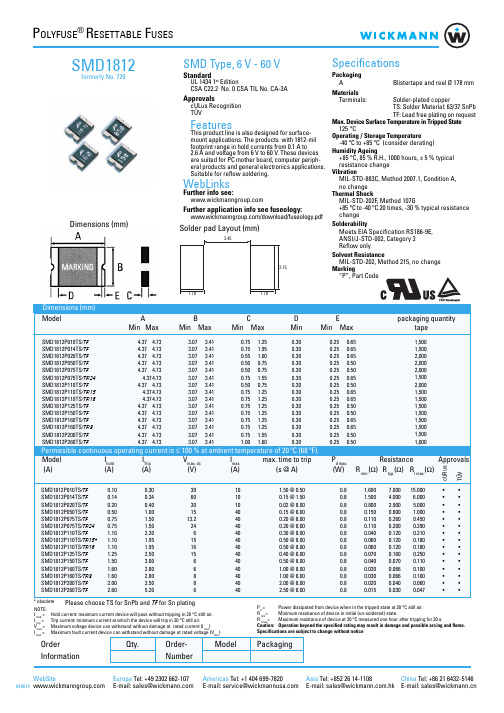
100.000 10.000 1.000
BC A
DEF
SMD1812
A:SMD1812P010TS/TF B:SMD1812P014TS/TF C:SMD1812P020TS/TF D:SMD1812P050TS/TF E:SMD1812P075TS/TF F:SMD1812P075TS/TF/24
0.75 1.25
0.30
0.75 1.95
0.30
0.55 1.00
0.30
0.50 0.75
0.30
0.50 0.75
0.30
0.75 1.55
0.30
0.50 0.75
0.30
0.75 1.25
0.30
0.75 1.25
0.30
SMD1812P125TS/TF
4.37 4.73
3.07 3.41
3.45
3.15
Specifications
Packaging A
Blistertape and reel Ø 178 mm
Materials
Terminals:
Solder-plated copper
TS: Solder Material: 63/37 SnPb
TF: Lead free plating on request
resistance change
Vibration
MIL-STD-883C, Method 2007.1, Condition A,
no change
Thermal Shock
MIL-STD-202F, Method 107G
+85 °C to -40 °C 20 times, -30 % typical resistance
TI型号大全35-迈锐国际
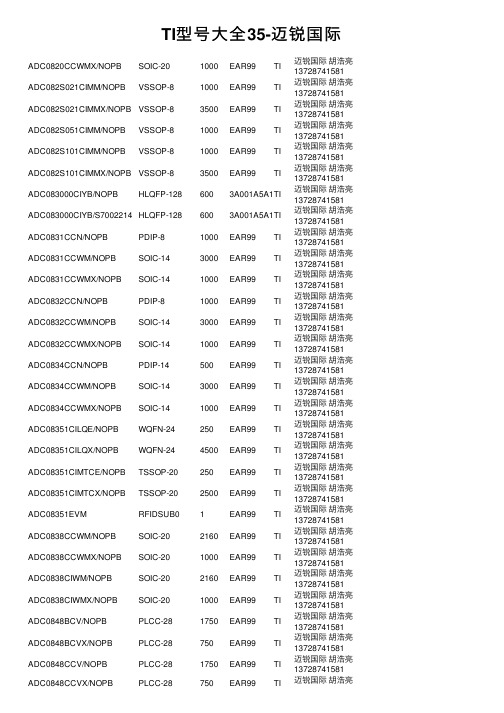
TI型号⼤全35-迈锐国际ADC0820CCWMX/NOPB SOIC-201000EAR99TI迈锐国际胡浩亮137********ADC082S021CIMM/NOPB VSSOP-81000EAR99TI迈锐国际胡浩亮137********ADC082S021CIMMX/NOPB VSSOP-83500EAR99TI迈锐国际胡浩亮137********ADC082S051CIMM/NOPB VSSOP-81000EAR99TI迈锐国际胡浩亮137********ADC082S101CIMM/NOPB VSSOP-81000EAR99TI迈锐国际胡浩亮137********ADC082S101CIMMX/NOPB VSSOP-83500EAR99TI迈锐国际胡浩亮137********ADC083000CIYB/NOPB HLQFP-1286003A001A5A1TI迈锐国际胡浩亮137********ADC083000CIYB/S7002214HLQFP-1286003A001A5A1TI迈锐国际胡浩亮137********ADC0831CCN/NOPB PDIP-81000EAR99TI迈锐国际胡浩亮137********ADC0831CCWM/NOPB SOIC-143000EAR99TI迈锐国际胡浩亮137********ADC0831CCWMX/NOPB SOIC-141000EAR99TI迈锐国际胡浩亮137********ADC0832CCN/NOPB PDIP-81000EAR99TI迈锐国际胡浩亮137********ADC0832CCWM/NOPB SOIC-143000EAR99TI迈锐国际胡浩亮137********ADC0832CCWMX/NOPB SOIC-141000EAR99TI迈锐国际胡浩亮137********ADC0834CCN/NOPB PDIP-14500EAR99TI迈锐国际胡浩亮137********ADC0834CCWM/NOPB SOIC-143000EAR99TI迈锐国际胡浩亮137********ADC0834CCWMX/NOPB SOIC-141000EAR99TI迈锐国际胡浩亮137********ADC08351CILQE/NOPB WQFN-24250EAR99TI迈锐国际胡浩亮137********ADC08351CILQX/NOPB WQFN-244500EAR99TI迈锐国际胡浩亮137********ADC08351CIMTCE/NOPB TSSOP-20250EAR99TI迈锐国际胡浩亮137********ADC08351CIMTCX/NOPB TSSOP-202500EAR99TI迈锐国际胡浩亮137********ADC08351EVM RFIDSUB01EAR99TI迈锐国际胡浩亮137********ADC0838CCWM/NOPB SOIC-202160EAR99TI迈锐国际胡浩亮137********ADC0838CCWMX/NOPB SOIC-201000EAR99TI迈锐国际胡浩亮137********ADC0838CIWM/NOPB SOIC-202160EAR99TI迈锐国际胡浩亮137********ADC0838CIWMX/NOPB SOIC-201000EAR99TI迈锐国际胡浩亮137********ADC0848BCV/NOPB PLCC-281750EAR99TI迈锐国际胡浩亮137********ADC0848BCVX/NOPB PLCC-28750EAR99TI迈锐国际胡浩亮137********ADC0848CCV/NOPB PLCC-281750EAR99TI迈锐国际胡浩亮137******** ADC0848CCVX/NOPB PLCC-28750EAR99TI迈锐国际胡浩亮137********ADC084S021CIMM/J7001218VSSOP-101000EAR99TI迈锐国际胡浩亮137********ADC084S021CIMM/NOPB VSSOP-101000EAR99TI迈锐国际胡浩亮137********ADC084S021CIMMX/NOPB VSSOP-103500EAR99TI迈锐国际胡浩亮137********ADC084S051CIMM/NOPB VSSOP-101000EAR99TI迈锐国际胡浩亮137********ADC084S101CIMM/NOPB VSSOP-101000EAR99TI迈锐国际胡浩亮137********ADC08500CIYB/NOPB HLQFP-1286003A991C1TI迈锐国际胡浩亮137********ADC08831IM SOIC-89500EAR99TI迈锐国际胡浩亮137********ADC08831IM/NOPB SOIC-89500EAR99TI迈锐国际胡浩亮137********ADC08831IMX/NOPB SOIC-82500EAR99TI迈锐国际胡浩亮137********ADC08832IMM/NOPB VSSOP-81000EAR99TI迈锐国际胡浩亮137********ADC08832IM/NOPB SOIC-89500EAR99TI迈锐国际胡浩亮137********ADC08832IMX/NOPB SOIC-82500EAR99TI迈锐国际胡浩亮137********ADC088S022CIMT TSSOP-169200EAR99TI迈锐国际胡浩亮137********ADC088S022CIMT/NOPB TSSOP-169200EAR99TI迈锐国际胡浩亮137********ADC088S022CIMTX/NOPB TSSOP-162500EAR99TI迈锐国际胡浩亮137********ADC088S052CIMT/NOPB TSSOP-169200EAR99TI迈锐国际胡浩亮137********ADC088S052CIMTX/NOPB TSSOP-162500EAR99TI迈锐国际胡浩亮137********ADC088S102CIMT/NOPB TSSOP-169200EAR99TI迈锐国际胡浩亮137********ADC088S102CIMTX/NOPB TSSOP-162500EAR99TI迈锐国际胡浩亮137********ADC08B200CIVS/NOPB TQFP-482500EAR99TI迈锐国际胡浩亮137********ADC08B200QCIVS/NOPB TQFP-482500EAR99TI迈锐国际胡浩亮137********ADC08B3000CIYB/NOPB HLQFP-1286003A991C1TI迈锐国际胡浩亮137********ADC08B3000RB/NOPB RFIDSUB01EAR99TI迈锐国际胡浩亮137********ADC08D1000CIYB/NOPB HLQFP-1286003A001A5A1TI迈锐国际胡浩亮137********ADC08D1010DIYB/NOPB HLQFP-1286003A001A5A1TI迈锐国际胡浩亮137********ADC08D1020CIYB/NOPB HLQFP-1286003A001A5A1TI迈锐国际胡浩亮137********ADC08D1500CIYB/NOPB HLQFP-1286003A001A5A1TI迈锐国际胡浩亮137********ADC08D1520CIYB/NOPB HLQFP-1286003A001A5A1TI迈锐国际胡浩亮137********ADC08D1520CIYB/S7002396HLQFP-1286003A001A5A1TI迈锐国际胡浩亮137********ADC08D1520CVAL RFIDSUB013A002H1A TI迈锐国际胡浩亮137********迈锐国际胡浩亮ADC08D1520RB/NOPB RFIDSUB013A002H1A TI137******** ADC08D1520WGFQV CQFP-128243A001A2C TI迈锐国际胡浩亮137********ADC08D1520WGMPR CQFP-128243A001A5A1TI迈锐国际胡浩亮137********ADC08D500CIYB/NOPB HLQFP-1286003A991C1TI迈锐国际胡浩亮137********ADC08D500CIYB/S7002554HLQFP-1286003A991C1TI迈锐国际胡浩亮137********ADC08D500CIYB/S7002952HLQFP-1286003A991C1TI迈锐国际胡浩亮137********ADC08D502CIYB/NOPB HLQFP-1286003A991C1TI迈锐国际胡浩亮137********ADC08DJ3200AAV FCBGA-1448403A001A5A1TI迈锐国际胡浩亮137********ADC08DJ3200AAVT FCBGA-1442503A001A5A1TI迈锐国际胡浩亮137********ADC08DJ3200EVM UNKNOWN-14413A002H1A TI迈锐国际胡浩亮137********ADC08DL500CIVV/NOPB LQFP-1446003A991C1TI迈锐国际胡浩亮137********ADC08DL502CIVV/NOPB LQFP-1446003A991C1TI迈锐国际胡浩亮137********ADC08L060CIMT/NOPB TSSOP-246100EAR99TI迈锐国际胡浩亮137********ADC08L060CIMTX/NOPB TSSOP-242500EAR99TI迈锐国际胡浩亮137********ADC08L060EVM RFIDSUB01EAR99TI迈锐国际胡浩亮137********ADC09QJ1300EVM RFIDSUB01EAR99TI迈锐国际胡浩亮137********ADC10040CIMT/NOPB TSSOP-284800EAR99TI迈锐国际胡浩亮137********ADC10040CIMTX/NOPB TSSOP-282500EAR99TI迈锐国际胡浩亮137********ADC10040QCIMT/NOPB TSSOP-284800EAR99TI迈锐国际胡浩亮137********ADC10040QCIMTX/NOPB TSSOP-282500EAR99TI迈锐国际胡浩亮137********ADC10065CIMT/NOPB TSSOP-284800EAR99TI迈锐国际胡浩亮137********ADC10065CIMTX/NOPB TSSOP-282500EAR99TI迈锐国际胡浩亮137********ADC10080CIMT/NOPB TSSOP-284800EAR99TI迈锐国际胡浩亮137********ADC10080CIMTX/NOPB TSSOP-282500EAR99TI迈锐国际胡浩亮137********ADC101C021CIMK/NOPB SOT-23-THN-61000EAR99TI迈锐国际胡浩亮137********ADC101C021CIMKX/NOPB SOT-23-THN-63000EAR99TI迈锐国际胡浩亮137********ADC101C021CIMM/NOPB VSSOP-81000EAR99TI迈锐国际胡浩亮137********ADC101C027CIMK/NOPB SOT-23-THN-61000EAR99TI迈锐国际胡浩亮137********ADC101C027CIMKX/NOPB SOT-23-THN-63000EAR99TI迈锐国际胡浩亮137********ADC101S021CIMF/NOPB SOT-23-61000EAR99TI迈锐国际胡浩亮137********ADC101S021CIMFX/NOPB SOT-23-63000EAR99TI迈锐国际胡浩亮137********迈锐国际胡浩亮ADC101S021CISD/NOPB WSON-61000EAR99TI137********ADC101S021CISDX/NOPB WSON-64500EAR99TI迈锐国际胡浩亮137********ADC101S051CIMF/NOPB SOT-23-61000EAR99TI迈锐国际胡浩亮137********ADC101S051CIMFX/NOPB SOT-23-63000EAR99TI迈锐国际胡浩亮137********ADC101S051QIMF/NOPB SOT-23-61000EAR99TI迈锐国际胡浩亮137********ADC101S051QIMFX/NOPB SOT-23-63000EAR99TI迈锐国际胡浩亮137********ADC101S101CIMF/NOPB SOT-23-61000EAR99TI迈锐国际胡浩亮137********ADC101S101CIMFX/NOPB SOT-23-63000EAR99TI迈锐国际胡浩亮137********ADC101S101CISD/NOPB WSON-61000EAR99TI迈锐国际胡浩亮137********。
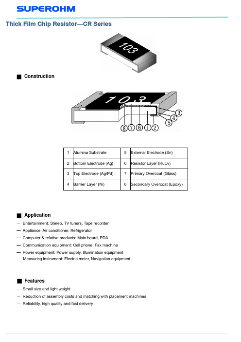
1812电阻规格书
Sony SS-00254
±5:±(1.0%+0.05Ω)
Leaching Soldering Heat Temperature Cycling
Sony SS-00254-9 260±5℃ for 30 seconds. JIS C 5201-1 clause 4.18 JIS C 5201-1 clause 4.19
E
Package E:Embossed Taping
05
Quantity 04:4000PCS 05:5000PCS
■ Test Procedures and Requirements
Test Item Temperature Coefficient of Resistance (T.C.R) Short Time Overload Test Method JIS C 5201-1 clause 4.8 Procedure Requirements
■ Application
— Entertainment: Stereo, TV tuners, Tape recorder ─ Appliance: Air conditioner, Refrigerator ─ Computer & relative products: Main board, PDA ─ Communication equipment: Cell phone, Fax machine ─ Power equipment: Power supply, Illumination equipment ─ Measuring instrument: Electric meter, Navigation equipment
( For Reflow Soldering )
SMD1812自恢复保险丝
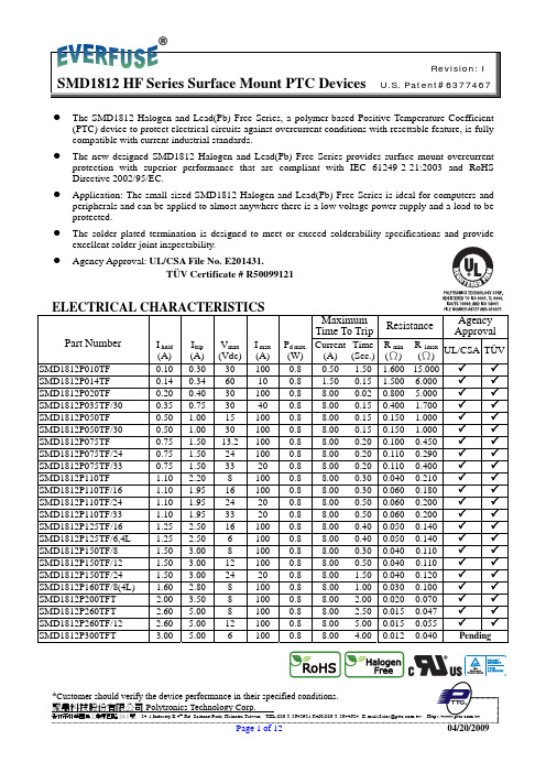
Revision: I
SMD1812 HF Series Surface Mount PTC Devices U.S. Patent#6377467
z The SMD1812 Halogen and Lead(Pb) Free Series, a polymer-based Positive Temperature Coefficient (PTC) device to protect electrical circuits against overcurrent conditions with resettable feature, is fully compatible with current industrial standards.
1.50 3.00 24 20
1.60 2.80 8 100
2.00 3.50 8 100
2.60 5.00 8 100
2.60 5.00 12 100
3.00 5.00 6 100
Maximum Time To Trip
Resistance
Agency Approval
Pd max. Current Time R min (W) (A) (Sec.) (Ω)
0.75 1.50 24 100
0.75 1.50 33 20
1.10 2.20 8 100
1.10 1.95 16 100
1.10 1.95 24 20
1.10 1.95 33 20
1.25 2.50 16 100
1.25 2.50 6 100
1.50 3.00 8 100
1.50 3.00 12 100
爱ixon 187806 爱ixon Moeller系列 xEffect - FRCmM-125型号

Eaton 187806Eaton Moeller series xEffect - FRCmM-125 Type B, Bfq and B+ RCCB. Residual current circuit-breaker, all-current sensitive, 80 A, 4p, 30 mA, type BGeneral specificationsEaton Moeller series xEffect - FRCmM-125 Type B, Bfq and B+ RCCB187806401508185490590 mm 80 mm 75 mm 0.48 kg RoHS conformIEC/EN 62423 IEC/EN 61008FRCMM-80/4/003-BProduct NameCatalog Number EANProduct Length/Depth Product Height Product Width Product Weight Compliances Certifications Model CodeFour-poleShort time-delayed80 A10 kA with back-up fuse 30 mAAll current sensitive3 kA (8/20 μs) surge-proof 240 V AC / 415 V AC240 V440 V4 kV0.03 A0.03 A50 Hz100 A (max. admissible back-up fuse) B800 A80 A gG/gL10 kA3 kA184 V AC - 440 V AC24000 operationsApplicationNumber of polesTripping timeAmperage RatingRated short-circuit strength Fault current rating Sensitivity typeImpulse withstand current Type Voltage rating (IEC/EN 60947-2)Rated operational voltage (Ue) - maxRated insulation voltage (Ui)Rated impulse withstand voltage (Uimp) Rated fault current - minRated fault current - maxFrequency ratingShort-circuit ratingLeakage current typeRated residual making and breaking capacity Admissible back-up fuse overload - max Rated short-time withstand current (Icw) Surge current capacityTest circuit rangePollution degreeLifespan, electricalSwitchgear for industrial and advanced commercial applicationsxEffect - Switchgear for industrial and advanced commercial applicationsFRCmMResidual current circuit breakersType B45 mm470 mm (4 SU)77.5 mmQuick attachment for top-hat rail IEC/EN 60715 DIN railAs requiredIP20, IP40 with suitable enclosureIP20Toggle-center postitionTwin-purpose terminals1.5 mm² - 16 mm² (2x)1.5 mm² - 50 mm²1.5 mm²50 mm²1.5 mm² - 16 mm² (2x)1.5 mm² - 5 mm²1.5 mm²16 mm²Finger and hand touch safe, DGUV VS3, EN 50274Red / green 80 A0 W22.5 W0 W0 W-25 °C75 °CMeets the product standard's requirements.Meets the product standard's requirements.Meets the product standard's requirements.Meets the product standard's requirements.Meets the product standard's requirements.Does not apply, since the entire switchgear needs to be evaluated.Does not apply, since the entire switchgear needs to be evaluated.Meets the product standard's requirements.Does not apply, since the entire switchgear needs to beFrameWidth in number of modular spacingsBuilt-in width (number of units)Built-in depthMounting MethodMounting positionDegree of protectionStatus indicationTerminals (top and bottom)Terminal capacity (solid wire)Connectable conductor cross section (solid-core) - min Connectable conductor cross section (solid-core) - max Terminal capacity (stranded cable)Connectable conductor cross section (multi-wired) - min Connectable conductor cross section (multi-wired) - max Terminal protectionContact position indicator color Rated operational current for specified heat dissipation (In) Heat dissipation per pole, current-dependentEquipment heat dissipation, current-dependentStatic heat dissipation, non-current-dependentHeat dissipation capacityAmbient operating temperature - minAmbient operating temperature - max10.2.2 Corrosion resistance10.2.3.1 Verification of thermal stability of enclosures10.2.3.2 Verification of resistance of insulating materials to normal heat10.2.3.3 Resist. of insul. mat. to abnormal heat/fire by internal elect. effects10.2.4 Resistance to ultra-violet (UV) radiation10.2.5 Lifting10.2.6 Mechanical impact10.2.7 Inscriptions10.3 Degree of protection of assemblies0.8 mm - 2 mm 20000 operations 25-55 °C / 90-95% relative humidity according to IEC 60068-2evaluated.Meets the product standard's requirements.Does not apply, since the entire switchgear needs to be evaluated.Does not apply, since the entire switchgear needs to be evaluated.Is the panel builder's responsibility.Is the panel builder's responsibility.Is the panel builder's responsibility.Is the panel builder's responsibility.Is the panel builder's responsibility.The panel builder is responsible for the temperature rise calculation. Eaton will provide heat dissipation data for the devices.Is the panel builder's responsibility. The specifications for the switchgear must be observed.Is the panel builder's responsibility. The specifications for the switchgear must be observed.The device meets the requirements, provided the information in the instruction leaflet (IL) is observed.Additional equipment possible Residual current circuit breaker eaton-rcd-application-guide-br019003en-en-us.pdf eaton-xeffect-frcmm40-80-type-b-rccb-catalog-ca003021en-en-us.pdfBusbar material thickness Lifespan, mechanical Climatic proofing10.4 Clearances and creepage distances 10.5 Protection against electric shock10.6 Incorporation of switching devices and components 10.7 Internal electrical circuits and connections 10.8 Connections for external conductors 10.9.2 Power-frequency electric strength 10.9.3 Impulse withstand voltage 10.9.4 Testing of enclosures made of insulating material 10.10 Temperature rise10.11 Short-circuit rating10.12 Electromagnetic compatibility10.13 Mechanical functionFeaturesFitted with:Application notesCataloguesEaton Corporation plc Eaton House30 Pembroke Road Dublin 4, Ireland © 2023 Eaton. All rights reserved. Eaton is a registered trademark.All other trademarks areproperty of their respectiveowners./socialmediaInterlocking deviceFRCmMType BResidual current circuit breakers eaton-xeffect-frcmm-125-rccb-catalog-ca003020en-en-us.pdfDA-DC-03_FRCmeaton-circuit-breaker-xeffect-frcmm-125-rccb-dimensions.jpg eaton-frcm-dimensions.jpgdfs_4.dwgdfs_4.stpeaton-xeffect-frcmm-125-rccb-wiring-diagram-003.jpgeaton-xeffect-frcmm-125-rccb-wiring-diagram.jpgSpecial features Used with Certification reports DrawingsmCAD model Wiring diagramsCurrent test marks as per inscriptionMaximum operating temperature is 75 °C: Starting at 40 °C, the max. permissible continuous current decreases by 1.2% for every 1 °C。
bladeRF 2.0 USB 3.0软定态电台说明 说明书

The bladeRF is an off-the-shelf USB 3.0 Software Defined Radio (SDR) that is easy and affordable for students and RF enthusiasts to explore wireless communications, yet provides a powerful waveform development platform expected by industry professionals.Support is available for Linux, macOS, and Windows. The bladeRF libraries, utilities, firmware, and platform HDL are released under open source licenses, and schematics are available online. The FPGA and USB 3.0 peripheral controller are programmable using vendor-supplied tools and SDKs that are available online, free of charge.Analog Devices RF Transceiver- 47 MHz to 6 GHz frequency range - 2x2 MIMO, 61.44 MHz sampling rate - 56 MHz filtered bandwidth (IBW) - Automatic gain control (AGC)- Real-time custom gain control tables controlledvia SPI and discrete external input pins - Automatic IQ and DC offset correction - 128-tap digital FIR filteringAltera Cyclone V FPGA- 49 kLE and 301 kLE variants available for customsignal processing and hardware acceleratorsFactory-calibrated SiTime MEMS VCTCXO- Calibrated within 1 Hz of 38.4 MHz- Taming supported via 12-bit DAC or ADF4002 PLL - MEMS oscillators provide superior reliability, aging,power supply noise rejection, and vibe/shock performance compared to quartz oscillatorsUSB 3.0 SuperSpeed Support- Cypress FX3 peripheral controller with integrated200 MHz ARM926EJ-S processor - Fully bus-powered over USB 3.0- External power option via 5 V DC barrel jack withautomatic switchoverFully Customizable- Expansion port with 32 I/O pins (LVDS available) - JTAG connectors- Triggered multi-device sampling synchronization - Onboard bias tee optionally provides 5 V to activeantennas and accessoriesSupported by popular third-party software 1- GNU Radio via gr-osmosdr - Pothos via SoapySDR - SDRangel - SDR Console- SDR# via sdrsharp-bladeRF - YateBTS- OpenAirInterface - srsUE & srsLTE- MathWorks MATLAB ® & Simulink ® support - Python bindingsApplications- Custom modem and waveform development - Wireless video (e.g., ATSC, DVB-T, DVB-S) - GPS reception and simulation - Whitespace exploration - GSM and LTE- ADS-B reception and simulation Operating Systems- Linux - Windows - macOS1 Third-party software is copyrighted by the respective owners and/or contributors.FEATURESSOFTWARE SUPPORT & APPLICATIONSMin Typ Max Unit RF SpecificationsADC/DAC Sample Rate 0.521261.44 MSPS ADC/DAC Resolution 12 bits VCTCXO Calibrated Accuracy326 ppb RF Tuning Range (RX) 70 6000 MHz RF Tuning Range (TX) 47 6000 MHz RF Bandwidth Filter <0.2 56 MHz CW Output Power +8 dBm FPGA SpecificationsLogic Elements 49 301 kLE Memory 3,383 13,917 kbits Variable-precision DSP Blocks 66 342Embedded 18x18 Multipliers 132 684Physical Specifications Dimensions 6.3 x 11.7 x 1.82.5 x 4.6 x 0.70cminchWeight 56 (0.12) g (lb.) Operating Temperature (A4/A9) 0 70 °C Operating Temperature (A9 Thermal) -40 85 °C Case Clear polycarbonate caseBT-100 BT-200 Wideband bias-tee powered Power Amplifier Wideband bias-tee powered Low Noise AmplifierSPECIFICATIONS2 The minimum ADC sampling rate is 25 MSPS. 521 KSPS is achieved using the maximum decimation of 12 and an additional FIR decimation of 4.3 VCTCXO is factory-calibrated to 1 Hz at 38.4 MHz. Temperature stability, aging, and other factors will affect accuracy after leaving the factory. All specifications are subject to change without notice.ACCESSORIES。
贴片压敏电阻TG1812系列型号参数规格书
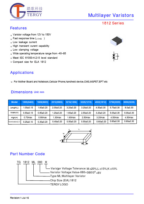
FeaturesApplicationsRevision:18-Jul-161812 SeriesVaristor voltage from 12V to 150V Fast response time ( )Low leakage current High transient curent capability Low clamping voltageWide operating temperature range from -40~85Meet IEC 61000-4-2/-5 level standarduuu uu u u uFor Mother Board and Notebook,Cellular Phone,handheld device,CMO S ,MO S FET,EFT etcDimensionsUnit: mm<1nS℃Compact size for ELA 1812uPart Number CodeTG 1812TERGY LOGO___________ML 080MChip Size (EIA):1812Type ML:Multilayer VaristorVaristor Voltage:Value-080=08X100=8V Varistor Voltage Tolerance:M:±20%;L:±15%;K:±10%Electriacl CharacteristicsRevision:18-Jul-16Surge Current Standard Waveform 1812 SeriesIEC61000-4-5 StandardsT1T2SEVERITY LEVELT1 T2 1 8 uS 20 uS 210 uS1000 uS8/20µs waveform currentOperating Temperature -40 ~ +85ºC Storage Temperature -40 ~ +125ºC Response Time <1 nsSolderability245±5ºC, 3±1sec Solder leach resistance 260±5ºC, 10±1sec Storage Temperature 5 ~ 40ºC Relative Humidity To 65% Taping Package Storage ConditionStorage Time12 Months maxGeneral Technical Data1812 SeriesRevision:18-Jul-16Environmental Reliability TestingCharacteristicTest method and descriptionHigh Temperature Storage The specimen shall be subjected to 125℃ for 1000 hours in a thermostatic bath withoutload and then stored at room temperature and humidity for 1 to 2 hours. The change ofvaristor voltage shall be within 10%.Step Temperature Period 1 -40±3℃30min ±3 2 Room Temperature 1~2hours3 125±2℃30min ±3Temperature CycleThe temperature cycle of specified temperature shall be repeated five times and then stored atroom temperature and humidity for one two hours. The change of varistor voltage shall be within 10%and mechanical damage shall be examined.4Room Temperature 1~2hoursHigh Temperature LoadAfter being continuously applied the maximum allowable voltage at 85℃ for 1000hours, the specimen shall be stored at room temperature and humidity for one or hours, the change of varistor voltage shall be within 10%.Damp Heat Load/Humidity LoadThe specimen should be subjected to 40℃,90 to 95%RH environment, and the maximum allowable voltage applied for 1000 hours, then stored at room temperature and humidity for one or two hours. The change of varistor voltage shall be within 10%.Low Temperature Storage The specimen should be subjected to -40℃, without load for 1000 hours and thenstored at room temperature for one two hours. The change of varistor voltage shall bewithin 10%.Recommended Soldering ConditionsNote that this product will be easily damaged by rapid heating, rapid cooling or local heating.Do not give heat shock over 100°C in the process of soldering. We recommend to take preheating and gradual coolingSoldering gun procedureNote the follows, in case of using solder gun for replacement. 1) The tip temperature must be less than 280 for the period within 3 seconds by using soldering gun under 30W2) The soldering gun tip shall not touch this product directly.Soldering volumeNote that excess of soldering volume will easily get crack the body of this product.Revision:18-Jul-161812 Series◆Carrier tape transparent cover tape should be heat-sealed to carry the products,and the reel should be used to reel the carrier tape.◆The adhesion of the heat-sealed cover tape shall be 40﹢20/﹣15grams.◆Both the head and the end portion of taping shall be empty for reel package and SMT auto-pickup machine.And a normal paper tape shall be connected in the head of taping for the operator handle.type A 0±0.10B 0±0.10K 0±0.10T ±0.05T 2±0.05D 0+0.10D 1±0.05P 1±0.10P 2±0.05P 0±0.05W ±0.20 E ±0.10 F ±0.050402 1.08 1.88 1.04 0.22 0.87 1.50 1.00 4.00 2.00 4.00 8.00 1.75 3.50 0603 1.08 1.88 1.04 0.22 1.17 1.50 1.00 4.00 2.00 4.00 8.00 1.75 3.50 0805 1.42 2.30 1.04 0.22 1.26 1.50 1.00 4.00 2.00 4.00 8.00 1.75 3.50 1206 1.88 3.50 1.27 0.20 1.49 1.50 1.00 4.00 2.00 4.00 8.00 1.75 3.50 1210 2.18 3.46 1.45 0.22 1.77 1.50 1.00 4.00 2.00 4.00 8.00 1.75 3.50 1812 3.66 4.95 1.74 0.25 1.99 1.50 1.50 8.00 2.00 4.00 12.00 1.75 5.50 2220 5.10 5.97 2.80 0.25 3.05 1.50 1.50 8.00 2.00 4.00 12.00 1.75 5.50 32205.50 8.50 2.80 0.30 3.50 1.50 1.50 8.00 2.00 4.00 16.00 1.757.50Packaging Dementions Unit:MillimetersReel DimensionsUnit:MillimetersType A B C D E W W 10402~1210178±160±0.513±0.221±0.22±0.59±0.5 1.5±0.151812~3220178±160±0.513.5±0.221±0.22±0.513.6±0.51.5±0.15Type 04020603080512061210181222203220Quantity100004000400030003000100010001000Packing Quantity。
1812封装系列贴片保险丝

Performance SpecificationModel MarkingMaximumResistance V max I max I hold I trip P d Time To Trip@25°C@25°C Typ.CurrentTimeR iminR1max(V dc)(A)(A)(A)(W)(A)(Sec)(Ω)(Ω)JSMD1812-010JS/01030.01000.100.300.80.5 1.500.75015.000 JSMD1812-010/60JS/01060.01000.100.300.80.5 1.500.75015.000 JSMD1812-014JS/01460.01000.140.340.8 1.50.150.650 6.000 JSMD1812-020JS/02030.01000.200.400.88.00.020.350 5.000 JSMD1812-020/60JS/0260.01000.200.400.88.00.020.350 5.000 JSMD1812-030JS/03030.01000.300.600.88.00.100.250 3.000 JSMD1812-035JS/03530.01000.300.600.88.00.100.250 3.000 JSMD1812-035/60JS/0360.01000.300.600.88.00.100.250 3.000 JSMD1812-050JS/05016.01000.50 1.000.88.00.150.150 1.000 JSMD1812-050/30JS/05030.01000.50 1.000.88.00.150.150 1.000 JSMD1812-050/60JS/0560.01000.50 1.000.88.00.150.150 1.000 JSMD1812-075JS/07516.01000.75 1.500.88.00.200.0900.450 JSMD1812-075/24JS/07524.01000.75 1.500.88.00.200.0900.450 JSMD1812-075/33JS/0733.01000.75 1.500.88.00.200.0900.450 JSMD1812-110JS/1108.0100 1.10 2.200.88.00.300.0500.250 JSMD1812-110/12JS/11012.0100 1.10 2.200.88.00.300.0500.250 JSMD1812-110/16JS/11016.0100 1.10 2.200.88.00.300.0500.250 JSMD1812-110/24JS/1124.0100 1.10 2.200.88.00.300.0500.250JSMD1812-110/33JS11/3333.0100 1.10 2.200.88.00.300.0500.250JSMD1812-125JS/1258.0100 1.25 2.500.88.00.400.0500.140 JSMD1812-125/12JS/12512.0100 1.25 2.500.88.00.400.0500.140 JSMD1812-125/16JS/1216.0100 1.25 2.500.88.00.400.0500.140 JSMD1812-150JS/1508.0100 1.50 3.000.88.00.500.0400.160 JSMD1812-150/12JS/15012.0100 1.50 3.000.88.00.500.0400.160 JSMD1812-150/16JS/1516.0100 1.50 3.000.88.00.500.0400.160 JSMD1812-150/24JS/15024.0100 1.50 3.000.88.00.500.0400.160 JSMD1812-160JS/1608.0100 1.60 2.800.88.0 1.000.0300.130 JSMD1812-160/12JS/16012.0100 1.60 2.800.88.0 1.000.0300.130 JSMD1812-160/16JS/1616.0100 1.60 2.800.88.0 1.000.0300.130 JSMD1812-200JS/2008.0100 2.00 4.000.88.0 2.000.0200.100 JSMD1812-200/12JS/2012.0100 2.00 4.000.88.0 2.000.0200.100 JSMD1812-200/16JS/2016.0100 2.00 4.000.88.0 2.000.0200.100JSMD1812-250JS/2508.0100 2.50 5.000.88.0 5.000.0150.075 JSMD1812-250/12JS/2512.0100 2.50 5.000.88.0 5.000.0150.075JSMD1812-250/16JS25/1616.0100 2.50 5.000.88.0 5.000.0150.075JSMD1812-260JS/2608.0100 2.60 5.000.88.0 2.500.0150.050 JSMD1812-260/12JS/26012.0100 2.60 5.000.88.0 2.500.0150.050JSMD1812-260/16JS26/1616.0100 2.60 5.000.88.0 2.500.0150.050JSMD1812-300JS/30012.0100 3.00 5.000.88.0 4.000.0120.040 JSMD1812-300/8JS/30012.0100 3.00 5.000.88.0 4.000.0120.040V max=Maximum operating voltage device can withstand without damage at rated current(Imax).I max=Maximum fault current device can withstand without damage at rated voltage(Vmax).I hold=Hold Current.Maximum current device will not trip in25°C still air.I trip=Trip Current.Minimum current at which the device will always trip in25°C still air.Pd=Power dissipation when device is in the tripped state in25°C still air environment at rated voltage.Ri min/max=Minimum/Maximum device resistance prior to tripping at25°C.R1max=Maximum device resistance is measured one hour post reflow.CAUTION:Operation beyond the specified ratings may result in damage and possible arcing and flame. Environmental SpecificationsTest Conditions Resistance change Passive aging+85°C,1000hrs.±5%typicalHumidity aging+85°C,85%R.H.,168hours±5%typicalThermal shock+85°C to-40°C,20times±33%typical Resistance to solvent MIL-STD-202,Method215No changeVibration MIL-STD-202,Method201No changeAmbient operating conditions:-40°C to+85°CMaximum surface temperature of the device in the tripped state is125°CAgency Approval and Environmental CompliancAgency File Number Regulation StandardUL EN2174532002/95/ECTUV pending EN14582Thermal Derating CurveThermal Derading ChartRecommended Hold Current(A)at Ambient Temperature(°C)ModelAmbient Operation Temperature -40°C-20°C 0°C 25°C 40°C 50°C 60°C 70°C 85°C JSMD1812-0100.160.140.120.100.080.070.060.050.03JSMD1812-0140.230.190.170.140.120.100.090.080.06JSMD1812-0200.290.260.230.200.170.150.140.120.10JSMD1812-0300.440.390.350.300.260.230.210.180.15JSMD1812-0350.500.450.400.350.300.260.240.200.16JSMD1812-0500.590.570.550.500.450.430.350.300.23JSMD1812-0751.100.990.870.750.630.570.490.450.35JSMD1812-110 1.60 1.45 1.28 1.100.920.830.710.660.52JSMD1812-1252.00 1.75 1.52 1.25 1.000.950.900.750.53JSMD1812-150 2.30 2.05 1.77 1.50 1.23 1.090.950.820.61JSMD1812-160 2.10 1.96 1.88 1.60 1.26 1.120.980.840.63JSMD1812-200 2.88 2.61 2.25 2.00 1.80 1.66 1.45 1.090.80JSMD1812-2503.27 3.04 2.88 2.50 2.21 2.07 1.92 1.78 1.57JSMD1812-260 3.90 3.42 2.96 2.60 2.33 2.07 1.94 1.35 1.00JSMD1812-3004.153.763.463.002.552.282.011.611.33Average Time-Current CurveTemperature (°C)80604020-20-40160140120100806040200Derating Curves for JSMD1812SeriesTP20~40S TP260TL217Tsmaxt L60~150s200150tsPreheat60~180s25t25°C to peak TimeRamp-down TsminCritical ZoneTL to TPRamp-upASoldering ParametersProfile Feature Pb-Free AssemblyAverage Ramp-Up Rate(Ts max to T p)3℃/second mac.Preheat-Temperature Min(Ts min)-Temperature Max(Ts max)-Time(Ts min to Ts max)150℃200℃60~180secondsTime maintained above:-Temperature(TL)-Time(tL)217℃60~150secondsPeak Temperature(Tp)260℃Ramp-Down Rate6℃/second max.Time25℃to Peak Temperature8minutes maxStorage Condition0℃~35℃,≤70%RHRecommended reflow methods:IR,vapor phase oven,hot air oven,N2environment for lead-freeRecommended maximum paste thickness is0.25mmDevices can be cleaned using standard industry methods and solvents.Note1:All temperature refer to topside of the package,measured on the package body surface.Note2:If reflow temperatures exceed the recommended profile,devices may not meet the performance requirements. Physical Dimensions(mm.)ModelA B C D E Min.Max.Min.Max.Min.Max.Min.Min.JSMD1812-010 4.37 4.73 3.07 3.410.50 1.000.300.25 JSMD1812-010/60 4.37 4.73 3.07 3.410.50 1.000.300.25 JSMD1812-014 4.37 4.73 3.07 3.410.50 1.300.300.25 JSMD1812-020 4.37 4.73 3.07 3.410.50 1.300.300.25 JSMD1812-020/60 4.37 4.73 3.07 3.410.50 1.000.300.25 JSMD1812-030 4.37 4.73 3.07 3.410.50 1.300.300.25 JSMD1812-035 4.37 4.73 3.07 3.410.65 1.150.300.25 JSMD1812-035/60 4.37 4.73 3.07 3.41 1.00 1.500.300.25 JSMD1812-050 4.37 4.73 3.07 3.410.400.900.300.25 JSMD1812-050/30 4.37 4.73 3.07 3.410.400.900.300.25 JSMD1812-050/60 4.37 4.73 3.07 3.41 1.10 1.800.300.25 JSMD1812-075 4.37 4.73 3.07 3.410.400.900.300.25 JSMD1812-075/24 4.37 4.73 3.07 3.410.60 1.300.300.25 JSMD1812-075/33 4.37 4.73 3.07 3.410.60 1.300.300.25 JSMD1812-110 4.37 4.73 3.07 3.410.400.900.300.25 JSMD1812-110/12 4.37 4.73 3.07 3.410.400.900.300.25 JSMD1812-110/16 4.37 4.73 3.07 3.410.60 1.300.300.25 JSMD1812-110/24 4.37 4.73 3.07 3.410.60 1.300.300.25 JSMD1812-110/33 4.37 4.73 3.07 3.41 1.10 1.800.300.25 JSMD1812-125 4.37 4.73 3.07 3.410.60 1.300.300.25 JSMD1812-125/12 4.37 4.73 3.07 3.410.60 1.300.300.25 JSMD1812-125/16 4.37 4.73 3.07 3.410.65 1.150.300.25 JSMD1812-150 4.37 4.73 3.07 3.410.400.900.300.25 JSMD1812-150/12 4.37 4.73 3.07 3.410.350.850.300.25 JSMD1812-150/16 4.37 4.73 3.07 3.410.60 1.300.300.25 JSMD1812-150/24 4.37 4.73 3.07 3.410.40 1.200.300.25 JSMD1812-160 4.37 4.73 3.07 3.410.400.900.300.25 JSMD1812-160/12 4.37 4.73 3.07 3.410.350.850.300.25 JSMD1812-160/16 4.37 4.73 3.07 3.41 1.10 1.800.300.25 JSMD1812-200 4.37 4.73 3.07 3.410.60 1.300.300.25 JSMD1812-200/12 4.37 4.73 3.07 3.410.65 1.150.300.25 JSMD1812-200/16 4.37 4.73 3.07 3.41 1.10 1.800.300.25 JSMD1812-250 4.37 4.73 3.07 3.410.350.850.300.25 JSMD1812-250/12 4.37 4.73 3.07 3.410.65 1.150.300.25 JSMD1812-250/16 4.37 4.73 3.07 3.41 1.00 1.500.300.25 JSMD1812-260 4.37 4.73 3.07 3.410.50 1.300.300.25 JSMD1812-260/12 4.37 4.73 3.07 3.410.65 1.150.300.25 JSMD1812-260/16 4.37 4.73 3.07 3.41 1.00 1.500.300.25 JSMD1812-300 4.37 4.73 3.07 3.410.50 1.300.300.25 JSMD1812-300/8 4.37 4.73 3.07 3.41 1.00 1.500.300.25Termination Pad CharacteristicsTerminal pad materials:Tin-plated Nickel-CopperTerminal pad solder ability:Meets EIA specification RS186-9E and ANSI/J-STD-002Category3.Recommended Pad Layout(mm.)1.78士0.13.2士0.1Packaging QuantityPart Number QuantityJSMD035/60.050/60.110/33.150/24.250/16.260/16.300.300/81,000pcs/reelJSMD010.010/60.014.020.020/60.030.035.075/33.110/24.125.16.150.16.160/16.200/12.200/16.250/12.260/121,500pcs/reelThe others2,000pcs/reel Tape&reel packaging per EIA481-1Tape And Reel Specifications(mm)EIA Tape Component DimensionsEIA Reel DimensionsACover tapeCarrier tapeEmbossed cavityStorage And Handling‧Storage conditions:35°C max,70%R.H.‧Devices may not meet specified performanceif storage conditions are exceeded.P0W2(measured at hub)N(hub dia.)W1(measured at hub)1.78士0.13..2士.1EmbossmentTD P2Cover E1F WB B0K0E2T P1GoverningSpecifications EIA481-1W12±0.3P0 4.0±0.10P18.0±0.10P2 2.0±0.05A0 3.5±0.10B0 5.1±0.10B1max. 5.9D0 1.50+0.1,-0F 5.5±0.05E1 1.75±0.10E2min.10.25T0.6T1max.0.1K00.9±0.1Leader min.390Trailer min.160Reel DimensionsA max.178N min.60W112.4±0.5W218.4Part Number SystemJ SMD1812-口口口/口口Special voltage Rating(Optional)Holding Current RatingDevice Dimensions:Length/width(Unit:1/100inch)Size4532mm/1812inchJKSEMICross ReferenceJKSEMICrossReferenceTYCO/Raychem LittelfuseBourns/Multifuse®Polytronics/EVERFUSE®SEA-LANDJSMD1812-010miniSMDC010F1812L010MF-MSMF010SMD1812P010TF mSMD010 JSMD1812-010/60-1812L010/60-SMD1812P010TF/60mSMD010-60V JSMD1812-014miniSMDC014F1812L014MF-MSMF014SMD1812P014TF mSMD014 JSMD1812-020miniSMDC020F1812L020MF-MSMF020SMD1812P020TF mSMD020 JSMD1812-020/60-1812L020/60MF-MSMF020/60-mSMD020-60V JSMD1812-030miniSMDC030F-MF-MSMF030-mSMD030 JSMD1812-035-----JSMD1812-035/60---SMD1812P035TF/60-JSMD1812-050miniSMDC050F1812L050MF-MSMF050SMD1812P050TF mSMD050 JSMD1812-050/30-1812L050/30MF-MSMF050/30X SMD1812P050TF/30-JSMD1812-050/60-1812L050/60-SMD1812P050TF/60mSMD050-60V JSMD1812-075miniSMDC075F1812L075MF-MSMF075SMD1812P075TF mSMD075 JSMD1812-075/24miniSMDC075F/241812L075/24MF-MSMF075/24SMD1812P075TF/24mSMD075-24V JSMD1812-075/33miniSMDC075F/331812L075/33MF-MSMF075/33X SMD1812P075TF/33mSMD075-33V JSMD1812-110-1812L110MF-MSMF110SMD1812P110TF mSMD110 JSMD1812-110/12-1812L110---JSMD1812-110/16miniSMDC110F/161812L110/16MF-MSMF110/16SMD1812P110TF/16mSMD110-16V JSMD1812-110/24miniSMDC110F/241812L110/24MF-MSMF110/24X SMD1812P110TF/24mSMD110-24V JSMD1812-110/33-1812L110/33-SMD1812P110TF/33mSMD110-33V JSMD1812-125miniSMDC125F-MF-MSMF125-mSMD125 JSMD1812-125/12-----JSMD1812-125/16miniSMDC125F/161812L125/16-SMD1812P125TF/16-JSMD1812-260miniSMDC260F1812L260--mSMD260 JSMD1812-260/12miniSMDC260F/121812L260/12---JSMD1812-260/16miniSMDC260F/161812L260/16MF-MSMF260SMD1812P260TFT-JSMD1812-300miniSMDC300F1812L300-SMD1812P300TFT mSMD300 JSMD1812-300/8-----“Raychem”is a registered trademark of Tyco Electronics.“Littelfuse”is a registered trademark of Littelfuse“Multifuse”is a registered trademark of bourns,Inc.“EVERFUSE”is a registered trademark of Polytronics Technology Corp.“SEA-LAND”is a registered trademark of Sea-Land electronic corp.Website:For additional information,please contact your local SalesRepresentative.©Copyright2016,jksemiis a registered trademark of jksemi All rights arereserved。
信昌贴片电容的型号1201812物料描述及信昌电容规格

信昌贴片电容的型号1206 1812物料描述及信昌电容规格随着经济的发展人们的收入水平逐渐提高,各种各样的家用电器进入了人们的生活,为了提高这些家用电器的品质,延长使用寿命,信昌贴片电容起到了不可替代的作用。
那么信昌贴片电容的型号1206 1812物料描述及信昌电容规格是怎样的呢,下面深圳市兴鸿宇科技有限公司为大家介绍信昌贴片电容的型号1206 1812物料描述及信昌电容规格信昌PDC我司现有电容规格:信昌PDC 是专业高压贴片电容产销公司,拥有完高压贴片电容主要用于电源滤波,电源降压,倍压,吸收浪涌保护IC, 基本工作原理就是充电放电,当然还有整流、振荡以及其它的作用等作用。
应用于电源电路,实现旁路、去藕、滤波和储能,常用于模块电源、液晶显示器inverter高压板,LED阻容降压电源,(INVERTER)逆变器、汽车氙气灯(HID电子安定器)、ASDL语音分离器、RJ45以太网接口、数码相机的闪光灯、LED圣誕灯灯串.节能灯和高频无极灯,电子镇流器等产品中;贴片压敏电阻MLCV产品在移动电话、PDA、MP3、MP4和电脑主板等领域有着广阔的应用前景.规格主要有:信昌电容--- FM31X123J501ECG 物料描述:1206 X7R 12NF +-5% 500V信昌电容--- FM31X474K101EEG 物料描述:1206 X7R 470NF +-10% 100V信昌电容--- FM43X224K251EFG(1) 物料描述:1812 X7R 220NF +-10% 250V信昌电容--- FM43X394K251EGG 物料描述:1812 X7R 390NF +-10% 250V (2.5M)信昌电容--- FM43X684K251EGG 物料描述:1812 X7R 680NF +-10% 250V (2.5M)信昌电容--- FN31X394J500EPG 物料描述:1206 X7R 390NF +-5% 50V信昌电容--- FS32X105K101EFG 物料描述:1210 X7R 1UF +-10% 100V信昌电容--- FS43X105K251EGG 物料描述:1812 X7R 1UF +-10% 250V信昌电容--- MA1206CG471J102ER 物料描述:1206 NPO 470PF +-5% 1KV信昌电容--- MA1210XR225K101ER 物料描述:1210 X7R 2.2UF +-10% 100V信昌电容--- MA1210XR471K202ER 物料描述:1210 X7R 470PF +-10%2KV信昌电容--- MA1812XR104K631ER 物料描述:1812 X7R 0.1UF +-10% 630V信昌电容--- MA1812XR224K251ER 物料描述:1812 X7R 0.22UF +-10% 250V信昌电容--- MA1812XR334K251ER 物料描述:1812 X7R 330NF +-10% 250V信昌电容--- MA1812XR474K251ER 物料描述:1812 X7R 0.47UF +-10% 250V信昌电容--- MA1812XR474K251ER(0.5) 物料描述:1812 X7R 0.47UF +-10% 250V信昌电容--- OP43X334K251EGG 物料描述:1812 X7R 0.33UF +-10% 250V信昌电容--- OP43X474K251EGG 物料描述:1812 X7R 0.47UF +-10% 250V信昌电容--- OP43X684K251EGG 物料描述:1812 X7R 0.68UF +-10% 250V更多库存与规格欢迎查询和索样~陶瓷积层贴片电容优势与特性:1、可以用做出小体积大容量的产品。
多种电源管理芯片代换

1200AP40 1200AP60、1203P60200D6、203D6 DAP8A 可互代203D6/1203P6 DAP8A2S0680 2S08803S0680 3S08805S0765 DP104、DP7048S0765C DP704加24V的稳压二极管ACT4060 ZA3020LV/MP1410/MP9141ACT4065 ZA3020/MP1580ACT4070 ZA3030/MP1583/MP1591MP1593/MP1430 ACT6311 LT1937ACT6906 LTC3406/AT1366/MP2104AMC2576 LM2576AMC2596 LM2596AMC3100 LTC3406/AT1366/MP2104AMC34063A AMC34063AMC7660 AJC1564AP8012 VIPer12AAP8022 VIPer22ADAP02 可用SG5841 /SG6841代换DAP02ALSZ SG6841DAP02ALSZ SG6841DAP7A、DP8A 203D6、1203P6DH321、DL321 Q100、DM0265RDM0465R DM/CM0565RDM0465R/DM0565R 用cm0565r代换(取掉4脚的稳压二极管)DP104 5S0765DP704 5S0765DP706 5S0765DP804 DP904FAN7601 LAF0001LD7552 可用SG6841代(改4脚电阻)LD7575PS 203D6改1脚100K电阻为24KOB2268CP OB2269CPOB2268CP SG6841改4脚100K电阻为20-47KOCP1451 TL1451/BA9741/SP9741/AP200OCP2150 LTC3406/AT1366/MP2104OCP2160 LTC3407OCP2576 LM2576OCP3601 MB3800OCP5001 TL5001OMC2596 LM2596/AP1501PT1301 RJ9266PT4101 AJC1648/MP3202PT4102 LT1937/AJC1896/AP1522/RJ9271/MP1540SG5841SZ SG6841DZ/SG6841DSM9621 RJ9621/AJC1642SP1937 LT1937/AJC1896/AP1522/RJ9271/MP1540STR-G5643D STR-G5653D、STR-G8653DTEA1507 TEA1533TEA1530 TEA1532对应引脚功能接入THX202H TFC719THX203H TFC718STOP246Y TOP247YVA7910 MAX1674/75 L6920 AJC1610VIPer12A VIPer22A[audio01]ICE2A165(1A/650V.31W);ICE2A265(2A/650V.52W);ICE2B0565(0.5A/650V.23W):ICE2B165(1A/650V.31W);ICE2B265(2A/650V.52W);ICE2A180(1A/800V.29W);ICE2A280(2A/800.50W).KA5H0365R, KA5M0365R, KA5L0365R, KA5M0365RN# u) t! u1 W1 B) R, PKA5L0365RN, KA5H0380R, KA5M0380R, KA5L0380R1、KA5Q1265RF/RT(大小两种体积)、KA5Q0765、FSCQ1265RT、KACQ1265RF、FSCQ0765RT、FSCQ1565Q这是一类的,这些型号的引脚功能全都一样,只是输出功率不一样。
维仕达 IMC-1812 表面贴装式铁氧体线圈数据手册说明书
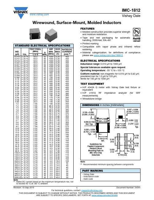
Wirewound, Surface-Mount, Molded InductorsNote(1)Rated DC current based on the maximum temperature rise, notto exceed 40 °C at +85 °C ambient FEATURES•Molded construction provides superior strength and moisture resistance•Tape and reel packaging for automatic handling, 2000/reel, EIA-481•Printed marking•Compatible with vapor phase and infrared reflow soldering•Material categorization: for definitions of compliance please see /doc?99912ELECTRICAL SPECIFICATIONSInductance range: 0.010 μH to 1000 μHSpecial tolerances available upon request Operating temperature: -55 °C to +125 °CCoilform material: non-magnetic for 0.010 μH to 0.82 μH; powdered iron for 1.0 μH to 120 μH; ferrite for 150 μH to 1000 μHTEST EQUIPMENT•H/P 4342A Q meter with Vishay Dale test fixture or equivalent•H/P 4191A RF impedance analyzer (for SRF measurements)•Wheatstone bridgeNote(1)Recommended minimum spacing between componentsSTANDARD ELECTRICAL SPECIFICATIONSIND.(μH)TOL.TEST FREQ.(MHz)QMIN.SRFMIN.(MHz)DCR MAX.(Ω)RATED DCCURRENT (mA) (1)L & Q0.010± 20 %50.05010000.204500.012± 20 %50.05010000.204500.018± 20 %50.05010000.204500.022± 20 %50.05010000.204500.027± 20 %50.05010000.204500.033± 20 %50.05010000.304500.039± 20 %50.05010000.304500.047± 20 %50.05010000.304500.056± 20 %50.0409000.354500.068± 20 %50.0408000.354500.082± 20 %50.0407000.404500.10± 20 %25.2306500.324500.12± 20 %25.2306000.304500.15± 20 %25.2305000.304500.18± 20 %25.2304000.354500.22± 20 %25.2303500.404500.27± 20 %25.2303000.454500.33± 20 %25.2302500.554300.39± 20 %25.2302200.703800.47± 10 %25.2301900.803550.56± 10 %25.230170 1.202850.68± 10 %25.230150 1.402700.82± 10 %25.230140 1.602501.0± 10 %7.96501000.504501.2± 10 %7.965080.00.554301.5± 10 %7.965070.00.604101.8± 10 %7.965060.00.653902.2± 10 %7.965055.00.703802.7± 10 %7.965050.00.753703.3± 10 %7.965045.00.803553.9± 10 %7.965040.00.903304.7± 10 %7.965035.0 1.003155.6± 10 %7.965033.0 1.103006.8± 10 %7.965027.0 1.202858.2± 10 %7.965025.0 1.4027010.0± 10 % 2.525020.0 1.6025012.0± 10 % 2.525018.0 2.0022515.0± 10 % 2.525017.0 2.5020018.0± 10 % 2.525015.0 2.8019022.0± 10 % 2.525013.0 3.2018027.0± 10 % 2.525012.0 3.6017033.0± 10 % 2.525011.0 4.0016039.0± 10 % 2.525011.0 4.5015047.0± 10 % 2.525010.0 5.0014056.0± 10 % 2.52509.0 5.5013568.0± 10 % 2.52509.0 6.0013082.0± 10 % 2.52508.07.00120100.0± 10 %0.79408.08.00110120.0± 10 %0.7940 6.08.00110150.0± 10 %0.7940 5.09.00105180.0± 10 %0.7940 5.09.50102220.0± 10 %0.7940 4.010.0100270.0± 10 %0.7940 4.012.092330.0± 10 %0.7940 3.514.085390.0± 10 %0.7940 3.016.080470.0± 10 %0.7940 3.026.062560.0± 10 %0.7930 3.030.050680.0± 10 %0.7930 3.030.050820.0± 10 %0.7930 2.535.0301000.0± 10 %0.2530 2.540.030PART MARKING- Vishay Dale- Inductance code - Date codeDESCRIPTIONIMC-181210 μH± 10 %ER e3MODEL INDUCTANCE VALUE INDUCTANCE TOLERANCE PACKAGE CODE JEDEC® LEAD (Pb)-FREE STANDARDGLOBAL PART NUMBERI M C1812E R100KPRODUCT FAMILY SIZE PACKAGECODEINDUCTANCEVALUETOL.Legal Disclaimer Notice VishayDisclaimerALL PRODUCT, PRODUCT SPECIFICATIONS AND DATA ARE SUBJECT TO CHANGE WITHOUT NOTICE TO IMPROV E RELIABILITY, FUNCTION OR DESIGN OR OTHERWISE.V ishay Intertechnology, Inc., its affiliates, agents, and employees, and all persons acting on its or their behalf (collectively,“Vishay”), disclaim any and all liability for any errors, inaccuracies or incompleteness contained in any datasheet or in any other disclosure relating to any product.Vishay makes no warranty, representation or guarantee regarding the suitability of the products for any particular purpose or the continuing production of any product. To the maximum extent permitted by applicable law, Vishay disclaims (i) any and all liability arising out of the application or use of any product, (ii) any and all liability, including without limitation special, consequential or incidental damages, and (iii) any and all implied warranties, including warranties of fitness for particular purpose, non-infringement and merchantability.Statements regarding the suitability of products for certain types of applications are based on Vishay's knowledge of typical requirements that are often placed on Vishay products in generic applications. Such statements are not binding statements about the suitability of products for a particular application. It is the customer's responsibility to validate that a particular product with the properties described in the product specification is suitable for use in a particular application. Parameters provided in datasheets and / or specifications may vary in different applications and performance may vary over time. All operating parameters, including typical parameters, must be validated for each customer application by the customer's technical experts. Product specifications do not expand or otherwise modify Vishay's terms and conditions of purchase, including but not limited to the warranty expressed therein.Hyperlinks included in this datasheet may direct users to third-party websites. These links are provided as a convenience and for informational purposes only. Inclusion of these hyperlinks does not constitute an endorsement or an approval by Vishay of any of the products, services or opinions of the corporation, organization or individual associated with the third-party website. Vishay disclaims any and all liability and bears no responsibility for the accuracy, legality or content of the third-party website or for that of subsequent links.Except as expressly indicated in writing, Vishay products are not designed for use in medical, life-saving, or life-sustaining applications or for any other application in which the failure of the Vishay product could result in personal injury or death. Customers using or selling Vishay products not expressly indicated for use in such applications do so at their own risk. Please contact authorized Vishay personnel to obtain written terms and conditions regarding products designed for such applications. No license, express or implied, by estoppel or otherwise, to any intellectual property rights is granted by this document or by any conduct of Vishay. Product names and markings noted herein may be trademarks of their respective owners.© 2022 VISHAY INTERTECHNOLOGY, INC. ALL RIGHTS RESERVED。
电源IC代换
发一些电源IC的代换资料DAP8A\DAP7A\LD7575\203D6\203X6\200D6可以直接代换,203d6是16v工作电压,而7575是30v ,代用要改启动电阻,可以用1200AP40直接代用OB2268,OB2269,DAP02,SG6841,SG5841DAP02\SG5841\2G684 1可以直接代换1200AP40\1200AP60\1203P60\1203AP10可以直接代换DM0465\CM0565\DM0565代换{要改电路}T O P246Y\T O P247Y可以直接代换。
大家来整理一个液晶电源的电源管理芯片集吧格式如下好了液晶品牌与型号电源管理芯片型号与封装可代换型号BENQ 71G+ 1200AP40 直插 1200AP10 1200AP60AOC 712SI EA1532A贴片三星型号忘记 DM0565R优派型号忘记 TOP245YNLG型号忘记 FAN7601飞利浦170s6 dap02alsz 贴片LG型号忘记 FAN7601 可以用LAF0001代飞利浦170s6 dap02alsz=sg6841美格WB9D7575PS清华同方XP911WD7575PS联想LXM -WL19AH LXM-WL19BH D7575PS(早期有的用:NCP1203D6) 联想LXM-17CH:1203D6方正17寸:1203D6与LD7575PS方正19寸:LD7575PSBenQ: FP94VW FP73G FP71G+S FP71G+G FP71GX等都是用:1200AP40 LG 22(南京同创):LAF001与STR W6252 。
LG 19寸:LAF001联想L193(福建-捷联代工):NCP1203D6PHILIPS 170S5FAN7601)PHILIPS 15寸(老产品):(FAN7601)LG型号忘记 FAN7601 可以用LAF0001代其他我知道的常用型号有SG6841DZ 贴片很多机器上用到SG5841SZ 贴片用SG6841DZ可以代用,DAP8A与203D6可代用还有LD7575可用203D6代用,只是1脚的对地电阻不同,LD7575是100K,203D6是24.1K,LP7552可用SG6841代用203D6 NCP1203D60R2 NCP1203D60R2G和DAP8A直接代换DAP02ALSZ与SG6841S可以互换1200AP40和1200AP60直接代换5S0765和DP104、DP704直接代换DP804和DP904直接代换2S0680和2S0880直接代换TEA1507和TEA1533直接代换LD7535兼容SG6848 (6849) / SG5701 / SG5848 /LD7535 (7550) / OB2262 (2263) / OB2278 (2279)RS2051LD7575和NCP1203、NCP1200 OB2268 SG5841 LD7552 OB2269 OB2268 RS2042CR6860兼容ACT30,CR6853兼容OB2263,CR6201兼容THX201,TFC718;CR6202兼容THX202,TFC719;CR6203兼容THX203,TFC718S。
主流COEDC芯片的对照表MS_Competitive_Analysis
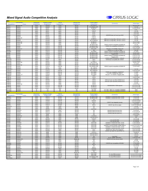
Mixed Signal Audio Competitive AnalysisADCResolution Dynamic Range THD+N Power Supply Competition CirrusComp/CirrusComp/Cirrus Comp/CirrusComp/Cirrus AD1871CS5341/4224/24105/10597/985A,3-5D/3-5*4,5,7,9,17,25AD1871CS535124/24105/10897/985A,3-5D/5A,3-5D*1,5,7,25AD1877CS534016/2492/10190/945A,5D/3-5*1,2,3,5,7,8,9,25AK4704CS534024/2496/10186/945/3-5*5,7,9,AK5353CS534024/2496/10184/943-5/3-5*1,5,7,25AK5354CS534020/2489/10184/943/3-5*1,2,5,7,25AK5355CS534016/2491/10185/943/3-5*1,2,5,7,25AK5356CS534520/2489/10584/953/3-5*AKM5356 does not have input MUX1,2,5,7,19,25AK5357CS534024/24102/10188/943-5/3-5*5,7,25AK5357CS5341/4224/24102/10588/983-5/3-5*1,5,7,25AK5365CS534524/24103/10594/955A,3D/3-5*AKM has 5 st Input Mux, CS has 6, no ALC 1,5,7,25AK5366CS534524/24103/10594/955A, 3.3-5D/3-5*AKM has 5 st Input Mux, CS has 6, no ALC1,5,7,25AK5380CS5341/4224/24105/10594/985A,3D/3-5* 3,5,7,17,9,25AK5381CS5341/4224/24106/10596/985A,3D/3-5*4,5,7,9,17,25AK5381CS535124/24106/10896/985A,3D/5A,3-5D*CS5351 footprint compatible w/CS5361/811,5,7,25AK5382CS536124/24113/114100/1055A,3D/5A,3-5D*CS5361 pin-compatible w/CS5351/811,7,8,10,25AK5383CS536124/24110/114103/1055A,3-5D/5A,3-5D*1,3,5,7,8,10,25AK5384CS5361x 224/24107/114100/1055/5A,3-5D*Chip-set = 2 X CS5361, lower cost 1,4,5,7,10,25AK5384CS536424/24107/114100/1055/5CS5364 is 4 ch ADC w/ TDM1,5,7,25AK5385A CS536124/24114/114103/1055A,3-5D/5*CS5351 footprint compatible w/CS5361/814,7,10,25AK5392CS536124/24116/114105/1055A,3D/5A,3-5D*CS5351 footprint compatible w/CS5361/813,4,5,8,10,25AK5392CS538124/24116/120105/1105A,3D/5A,3-5D*Flagship ADC3,4,5,8,10,25AK5393CS536124/24117/114105/1055A,3D/5A,3-5D*CS5351 footprint compatible w/CS5361/811,5,8,10,11,25AK5393CS538124/24117/120105/1105A,3D/5A,3-5D*Flagship ADC1,5,8,10,11,25AK5394A CS538124/24123/120110/1105A,3D/5A,3-5D*CS5381 power consumption <325mW 4,8,10,11,25PCM1800CS534020/2495/10188/945/3-5CS5340 pin-compatible with CS53411,2,3,5,7,8,9,25PCM1801CS534016/2493/10188/945/3-51,2,3,5,7,8,9,25PCM1802CS5341/4224/24105/10596/985A,3.3D/3-5*3,5,8,9,17,25PCM1802CS535124/24105/10896/985A,3.3D/5A,3-5D*1,5,7,8,25PCM1803CS5341/4224/24103/10595/985A,3.3D/5A,3-5D*1,3,5,7,8,9,10,25PCM1804CS536124/24112/114102/1055A,3.3D/5A,3-5D*CS5351 footprint compatible w/CS5361/811,3,7,8,10,25PCM1807CS534024/2499/10193/945A, 3.3D/3-5PCM1850/1CS534524/24101/10593/955A,3.3D/3-5*1,5,7,25PCM4201CS536124/24112/114105/1055A,1.8-5D/3-5*1,4,5,10,17,25PCM4202CS538124/24118/120102/1105A,3.3D/5*CS4381 pin-compatible w/CS5351/611,7,10,25PCM4204CS536424/24118/114102/1055A,3.3D/5* 4 ch ADC, CS4364 has TDM I/F 4,7,25PCM4204CS5381 x 224/24118/120102/1105A,3.3D/5*Chip-set = 2 X CS5381, Flagship ADC1,7,10,25WM8737CS534024/2495/10190/943/3-51,5,7,25WM8738CS534024/2490/10187/943-5/3-51,3,4,5,7,9,25WM8739CS534024/2490/10184/943/3-51,5,7,25WM8773CS534524/24102/10589/953-5/3-5WM has 8 pair input Mux,CS5345 has 61,3,5,7,25WM8775 CS534524/24102/10590/953-5/3-5WM has 4 pair Input Mux,CS5345 has 61,3,5,7,25WM8782CS534024/24102/10190/943-5/3-53,7,9,25WM8782CS5341/4224/24102/10590/983-5/3-51,3,7,9,17,25WM8785CS536124/24111/114102/1055A,3D/3-5*CS5364/66/68 if TDM required1,5,7,9,10,17,25WM8786CS536124/24111/114102/1055A,3D/3-5*1,5,7,9,10,17,25UDA1360CS534020/2497/10185/94 2.4-3.6/3-51,2,4,5,6, 7,8,9,25No Comp.CS5366241141055A,3-5D* 6 ch ADC, TDM, pin compatible CS5368/6410,25No Comp.CS5368241141055A,3-5D*8 ch ADC, TDM, pin compatible CS5366/6410,25DACResolution Dynamic Range THD+N Power Supply Competition CirrusComp/CirrusComp/Cirrus Comp/CirrusComp/Cirrus AD1833CS4362A 24/24108/11495/1005A,3D/5A,2.5D*CS4362A is multi-bit 6ch DAC, 2.5VD 1,7,8,12,16AD1833A CS4362A 24/24110/11495/1005A,3D/5A,2.5D*CS4362A is multi-bit 6ch DAC, 2.5VD1,7,8,12,16AD1852CS439224/24114/114102/1005/53,4,12,16,25AD1853CS439824/24116/120104/1075/5A,3D*1,3,7,10,13,14,25AD1854CS435124/24112/112101/1005/9-12CS4351 has integrated op-amp 5,17,18,25,26AD1854CS439224/24112/114101/1005/51,3.4,7,25AD1855CS435124/24110/11297/1005/9-12CS4351 has 2Vrms output1,3,5,7,17,18,25,26AD1857/8CS433420/2494/9690/885/51,2,3,26AD1859CS433418/2494/9688/885/51,2,3,7,26AD1955CS439824/24120/120110/1075/5A,3-5D*4,10,12,13,14,16,17,25AD1958CS4391A 24/24109/10896/945/5CS4391A Does Not Have PLL 4,10,12,25AD1958CS439224/24109/11496/1005/5CS4391A Does Not Have PLL 1,7,10,12,16,25AD1959CS4391A 24/24108/10894/945/5CS4392 Does Not Have PLL4,10,12,25AK4351CS433418/2496/9688/885/52,3,6,7,25,26AK4352CS4341CZ 18/2496/10189/89 1.8-3.6/3-51,6,26AK4352CS43L4318/2496/9689/85 1.8-3.6/1.8-3.32,6AK4353CS434424/24102/10590/953-5.5/3-51,3,7,17,26AK4355CS436024/24106/10290/915/3-5Low cost 6ch DAC 4,7,8,25,26AK4355CS436124/24106/10590/955/3-5Low cost 6ch DAC4,7,8,25,26AK4356CS4362A 24/24112/11494/1005/5A,2.5D*CS4362A is multi-bit 6ch DAC, 2.5VD 1,7,8,12,16,25AK4357CS4362A 24/24106/11490/1005/5A,2.5D*CS4362A is multi-bit 6ch DAC, 2.5VD 1,7,8,12,16,25AK4358CS438524/24112/11494/1005/5A,2.5D*CS4385 is multi-bit 8chDAC w/DSD,TDM I/F 1,7,8,12,13,14,16,17,25AK4358CS4382A 24/24112/11494/1005/5A,2.5D*CS4382A is multi-bit 8ch DAC, 2.5VD 1,7,8,12,16,25AK4359CS4382A 24/24106/11494/1005/5A,2.5D*CS4382A is multi-bit 8ch DAC, 2.5VD 1,5,7,8,12,16,25AK4363CS434424/24102/10590/955/3-5AK4363 has video clock locked PLL 1,3,5,7,9,17,26AK4364CS434424/24102/10590/955/3-5AK4364 has video PLL and S/PDIF tcx1,3,5,7,9,17,26AK4365CS43L4320/2488/9684/853/1.8-3.31,2,3,6,7,8AK4366CS43L4324/2492/9658/85 2.2-3.3/1.8-3.31,6,7,8AK4367CS43L4324/2492/9658/85 2.2-3.6/1.8-3.31,3,6,7,8AK4380CS433424/24100/9688/885/58-pin DAC3,4,26AK4380CS434424/24100/10588/955/3-5No 3V 100dB+ AKM DACs 1,3,5,7,9,17,26AK4380CS4341/41A 24/24100/10188/915/3-5CS4341/41A has volume control1,7,9AK4381CS4391A 24/24108/10894/945/54,12,25AK4381CS434424/24108/10594/955/3-53,4,7,17,26AK4382A CS439224/24112/11494/1005/5CS4391A pin-compatible w/CS43921,7,12,16,25AK4382A CS435124/24112/11294/1005/9-127,17,18,25AK4383CS439224/24112/11494/1005/51,3,7,12,16AK4383CS435124/24112/11294/1005/9-127,17,18AK4384CS4391A 24/24106/10894/943-5.5/3-51,12,25AK4384CS434424/24106/10594/953-5.5/3-53,7,17,26AK4385CS4391A 24/24108/10894/945/510,12,25AK4386CS4341/41A 24/24100/10186/89 2.2-3.6/3-51,7,26AK4393CS439824/24120/120100/1075/5A,3-5D*On-chip DSD processor 5,10,12,13,14,15,16,25AK4394/95CS439824/24120/120100/1075/5A,3-5D*On-chip DSD processor 10,12,13,14,15,16,25AK4396CS439824/24120/120100/1075A,3-5D/5A,3-5D*On-chip DSD processor10,12,13,14,15,16,25DAC 3555ACS434132/24103/10280/913.3/3-5Page 1 of 5CommentsPart NumberSample Rate Comp/CirrusAdvantages Advantages Part NumberComments96/19296/19296/19296/19296/19248/19296/19296/19296/19296/19296/19248/19296/19296/19296/192192/19296/19296/19296/192192/19248/19248/19296/19296/192192/19248/19248/19296/19296/19296/192192/19296/19296/192192/192192/192192/19296/19296/19296/19296/19296/192192/192192/192192/192192/19248/192192192Sample Rate Comp/Cirrus 192/192192/192192/192192/19296/19296/19296/19296/9696/96192/192192/192192/192192/19248/9648/9648/9696/192192/192192/192192/192192/192192/192192/192192/10096/19296/19248/9648/9648/9696/9696/19296/96,192192/192192/192192/192192/192192/192192/192192/192192/192192/19296/96,19296/192192/192192/19296/9696/192DAC ContinuedResolution Dynamic Range THD+N Power Supply Competition CirrusComp/CirrusComp/Cirrus Comp/CirrusComp/Cirrus DSD1608CS4382A 24/24105/11494/1005A,3.3D/5A,2.5D*CS4382A is multi-bit 8ch DAC, 2.5VD1,7,8,12,16,25DSD1700CS4398NA/24110/120100/1075/5A,3-5D*On-chip DSD processor1,4,5,7,10,13,14,16,25DSD1702CS4391A/9224/24106/108,11496/94,1005A,3D/51,7,10,12,16,26DSD1791CS439224/24113/114100/1005A,3.3D/51,3,12,25DSD1792/92A CS439824/24127/120106/1075A,3.3D/5A,3D*Reference 1/2004 sales bit on extranet 3,7,12,13,14,25DSD1793CS439224/24113/114100/1005A3.3D/5A,3D*1,3,12,25DSD1794/94A CS439824/24127/120106/1075A,3.3D/5A,3D*Reference 1/2004 sales bit on extranet3,7,12,13,14,25DSD1796CS439824/24127/120106/1075A,3.3D/5A,3D*3,7,12,13,14,25HT82V738CS433424/2494/9688/883-5/53, 6PCM1600CS4362A 24/24105/11495/1005A,3.3D/2.5D,5A*CS4362A is multi-bit 6ch DAC, 2.5VD 1,5,7,8,12,16,25PCM1601CS4362A 24/24105/11495/1005A,3.3D/2.5D,5A*CS4362A is multi-bit 6ch DAC, 2.5VD 1,5,7,8,12,16,25PCM1601CS436024/24105/10295/915A,3.3D/3-5*4,5,25,26PCM1602CS4362A 24/24105/11495/1005A,3.3D/2.5D,5A*CS4362A is multi-bit 6ch DAC, 2.5VD 1,7,8,12,16,25PCM1602CS436124/24105/10595/955A,3.3D/3-5*3,4,7,9,10,17,25,26PCM1604/5CS4362A 24/24105/11495/1005A,3.3D/2.5D,5A*CS4362A is multi-bit 6ch DAC, 2.5VD1,7,8,12,16,25PCM1604/5CS436024/24105/10295/915A,3.3D/3-5*4,25,26PCM1606CS436124/24103/10590/955/3-51,3,4,7,9,10,17,25,26PCM1608CS4382A 24/24105/11490/1005A,3.3D/2.5D,5A*CS4382A is multi-bit 8ch DAC, 2.5VD 1,7,8,12,16,25PCM1608Chip-set 24/24105/102,10590/91,955A,3.3D/3-5* 6 ch DAC, CS4360 + CS4344 = Chip-set 1,7,17,25,26PCM1608Chip-set 24/24105/105,10590/95,955A,3.3D/3-5*6 ch DAC, CS4361 + CS4344 = Chip-set1,3,4,7,10,17,25,26PCM1680Chip-set 24/24105/105,10594/95,955/3-5*CS4361 + CS4344 = Chip-set PCM1710CS435120/24110/11292/1005/9-12CS4351 has integrated op-amp1,2,3,5,7,17,18,25,26PCM1716CS434424/24106/10596/955/3-53,4,5,17,26PCM1716CS435124/24106/11296/1005/9-121,5,7,17,18,25,26PCM1717CS433418/2496/9690/883-5/5,2,3,4,6,26PCM1718CS433418/2496/9690/883-5/52,3,4,6,26PCM1719CS433418/2496/9688/885/52,3,4,6,26PCM1720CS433424/2496/9688/885/53,4,6,26PCM1723CS433424/2494/9689/885/51,3,4,6,26PCM1725CS433416/2495/9683/885/51,2,3,26PCM1727CS433424/2492/9689/885/5CS4344 Does Not Have PLL1,3,26PCM1728CS434424/24106/10596/955/3-53,5,8,17,26PCM1730CS439824/24117/120108/1075A,3.3D/5A,3D*1,11,13,14,25PCM1733CS433418/2496/9683/885/51,2,3,4,7,26PCM1737CS4391A 24/24106/10894/945A,3.3D/5*1,3,12,25,26PCM1737CS434424/24106/10594/955A,3.3D/3-5*7,12,13,17,14,26PCM1738CS439224/24117/114107/1005/53,4,12,16,25PCM1738CS439824/24117/120107/1075/5A,3D*1,3,12,13,14,25PCM1739CS435124/24106/11296/1005A,3.3D/9-12*CS4351 has integrated op-amp 1,3,7,17,18,25,26PCM1739CS434424/24108/10596/955A,3.3D/3-5*3,4,17,26PCM1740CS434424/2494/10589/95 5/3-5CS4344 Does Not Have PLL 1,3,7,8,17,26PCM1741CS434124/2498/10286/91 3.3/3-51,7,8PCM1742 CS434424/24100/10590/955A,3.3D/3-5*CS4341A if volume control required 1,7,9,17PCM1744CS433424/2495/9683/885/5Footprint compatible w/CS4340/11,3,7,26PCM1748CS434424/24100/10590/955A,3D/3-5*CS4341/41A if volume control required 1,5,7,9,17PCM1753/4/5CS4391A 24/24106/10894/945/5CS4391A pin-compatible w/CS43921,12,25PCM1753/4/5CS434424/24106/10594/955/3-5CS4341/41A if volume control required4,8,9,17PCM1770/1CS43L4324/2498/9660/85 1.8-3.3/1.8-3.36,7PCM1772/3CS43L4324/2498/9660/85 1.8-3.3/1.8-3.36,7PCM1774/5CS43L4324/2498/9660/85 1.8-3.3/1.8-3.36,7PCM1780/81/82CS434424/24106/10594/955/3-5PCM1780/81/82CS4391A 24/24106/10894/945/5If control port features are requiredPCM1791A CS439224/24113/114100/1005/51,12,16,25PCM1791A CS435124/24113/112100/1005/517,18,25,26PCM1792/92A CS439824/24127/120108/1075A,3.3D/5A,3D*Reference 1/2004 sales bit on extranet3,12,13,14,25PCM1793CS439224/24113/114100/1005A,3.3D/5*1,3,12,25PCM1793CS435124/24113/112100/1005A,3.3D/9-12*17,18,25,26PCM1794/94A CS439824/24127/120108/1075A,3.3D/5*Reference 1/2004 sales bit on extranet3,12,13,14,25PCM1796CS439824/24123/120106/1075A,3.3D/5*3,12,13,14,25PCM1798CS439824/24123/120106/1075A,3.3D/5*3,12,13,14,25PCM2704Chip-set 16/2496/10584/953-5/3-5CS4344+CS8406, TI has USB and H/P out PCM2705Chip-set 16/2496/10584/953-5/3-5CS4344+CS8406, TI has USB and H/P out PCM2706Chip-set 16/2496/10584/953-5/3-5CS4344+CS8406, TI has USB and H/P out PCM2707Chip-set 16/2496/10584/953-5/3-5CS4344+CS8406, TI has USB and H/P out PCM4104CS436524/24118/114100/1005A,3.3D/5A,2.5D*CS4365 is multi-bit 6chDAC w/DSD,TDM I/F 3,8,12,16,17,13,14,25PCM4104CS4362A 24/24118/114100/1005A,3.3D/5A,2.5D*CS4362A is multi-bit 6ch DAC, 2.5VD 3,8,12,16,25TLV320DAC23CS4341CZ 24/24100/10188/893-5/3-51,7,26WM8521CS434424/2498/10581/959-12A,3D/3-5CS4351 if integrated op-amp is required1,3,4,7,9,10,17,25,26WM8706CS434424/24105/10597/953-5.5/3-54,17WM8711CS4341CZ 24/24100/10190/89 1.4-3.6/3-51,26WM8714CS433424/2495/9690/885/51,3,26WM8716CS439224/24110/11492/1003-5/51,3,7,12,16,25WM8716CS435124/24110/11292/1003-5/9-121,7,17,18,25,26WM8718CS439224/24111/114100/1003-5.5/5WM8718 has 20dB THD+N slide typ to max 1,3,12,16,25WM8718CS435124/24111/112100/1003-5/9-12WM8718 has 20dB THD+N slide typ to max 1,17,18,25,26WM8720CS434424/24102/10590/953-5/3-5CS4341/41A if volume control required 1,3,5,7,17WM8721CS4341CZ 24/24100/10190/89 1.42.-3.6/3-51,26WM8722CS434424/24102/10595/953-5/3-5CS4341/41A if volume control required 1,3,5,17WM8725CS433424/2492/9680/883-5/51,3,7,26WM8726CS434424/24100/10588/953-5/3-5CS4341/41A if volume control required 1,17,26WM8727CS433424/2498/9684/883-5.5/5CS4341/41A if volume control required 4,7,26WM8727CS434424/2498/10584/953-5.5/3-5CS4341/41A if volume control required1,5,7,26WM8728CS4391A 24/24106/10896/943-5/51,8,12,17,25WM8728CS434424/24106/10596/953-5/3-54,17,26WM8729CS434424/24106/10597/953-5/3-54,17,26WM8733CS4341CZ 24/24102/10190/893-5/3-54,26WM8736CS436024/24102/10295/913-5/3-56ch DAC 4,5,25,26WM8736CS436124/24102/10595/953-5/3-56ch DAC1,3,4,5,10,17,25,26WM8740CS439824/24117/120104/1075/5A,3-5D*1,7,12,13,14,25WM8746CS436124/24106/10596/953-5/3-56ch DAC3,4,10,25,26WM8746CS4362A 24/24106/11496/1003-5A,3-5D/5A,2.5D*CS4362A is multi-bit 6ch DAC, 2.5VD1,7,8,12,16,25WM8751CS43L4324/2498/9686/85 1.8-3.6/1.8-3.34WM8759CS4341CZ 24/24100/10188/89 2.7-5.5/3-51,7,26WM8761CS434424/24100/10590/953-5/3-51,3,7,17,26WM8762CS434424/2498/10584/953-5/3-51,3,7,17,26WM8763/4/5CS436024/24103/10290/913-5A,3.3D/3-5*6ch DAC3,4,7,12,16,25,26WM8760CS4382A 24/24103/11490/1003-5A,3.3D/5A,2.5D*CS4382A is multi-bit 8ch DAC, 2.5VD1,7,8,12,16,25WM8766CS436124/24103/10590/953-5A,3.3D/3-5*1,3,4,7,9,10,17,25,26WM8768Chip-set 24/24103/105,10590/95,953-5A,3.3D/3-5*CS4361 + CS4344 = Chip-set1,4,7,9,10,17,25,26WM8955CS43L4324/2498/9686/85 1.8-3.6/1.8-3.33,4UDA1334CS4341CZ24/24100/10190/891.8-3.6/3-51,4,26Page 2 of 5Part NumberCommentsAdvantages Sample Rate Comp/Cirrus 192/192NA/192192/192192/192192/192192/192192/192192/19296/19296/19296/19296/96192/192192/192192/192192/192192/192192/192192/192192/19248/19296/19296/19248/9648/9648/9696/9696/9696/9696/9696/192192/192192/192192/192192/19296/96192/192192/192192/192192/192192/192192/192192/192192/19248/9648/96192/192192/192192/192192/192192/19248/19248/19248/19248/192192/192192/19296/96192/192192/19296/9696/96192/192192/192192/192192/19296/19296/9696/19296/96192/19296/9696/192192/192192/192192/19296/9696/19296/192192/192192/192192/19296/96192/96192/192192/192192/192192/192192/192192/19296/9696/96192/192192/192192/19248/9696/96192/19296/9696/192192/192Stereo CodecResolution Dynamic Range THD+N Power Supply Competition Cirrus Comp/CirrusComp/Cirrus Comp/Cirrus Comp/CirrusADAV801/80324102ADC,100DAC 85DADC,96DAC 3.3CS8416 + CS4245 = Chip-set Chip-set24105ADC,105DAC 95ADC,95DAC 3-5CS8421 if SRC requiredADAV802/80424102ADC,103DAC 85DAC,96ADC 3.3ADAV802 has sample rate converter,CS426524105ADC,105DAC 95ADC,95DAC 3-5differential DAC outputs ADAV83224102ADC,103DAC 85DAC,96ADC 3.3ADAV832 has SPI interface CS424524105ADC,105DAC 95ADC,95DAC 3-5CS4245 has 6 ch input MUXAK4522/23/2520100ADC,100DAC 92ADC,90DAC 5A,3D*CS427024101ADC,105DAC 94ADC,95DAC 3-5AK452424100ADC,110DAC 90ADC, 94DAC 5CS427124108ADC,114DAC 98ADC,100DAC 5A,3-5D*AK452824108ADC,110DAC 94ADC, 94DAC 5A,3D*CS427224114ADC,114DAC 100ADC,100DAC 5A,3-5D*CS4272 has on chip oscillator AK452824108ADC,110DAC 94ADC,94DAC 5A,3D*CS427124108ADC,114DAC 98ADC,100DAC 5A,3-5D*AK452824108ADC,110DAC 94ADC, 94DAC 5A,3D*AK4528 has analog volume control,mixer,CS427224114ADC,114DAC 100ADC,100DAC 5A,3-5D*CS4272 has on chip oscillator AK458424100ADC,104DAC 90ADC, 94DAC 5S/E or Diff I/O with a Rx and Tx.CS4272 Chipset24114ADC,114DAC 100ADC,100DAC5A,3-5D*If need Rx Cs8416 IfTx CS84061AK462024113ADC,115DAC --5A,3D*CS427224114ADC,114DAC 100ADC,100DAC 5A,3-5D*CS4272 has on chip oscillator1PCM301024102ADC,104DAC 95ADC,96DAC 5A,3D*CS427024105ADC,105DAC 96ADC,95DAC3-5PCM305224101ADC,101DAC TBD5CS426524105ADC,105DAC 95ADC,95DAC 3-5WM8590/124102ADC,110DAC 90ADC/97DAC 2.7-5CS424524105ADC,105DAC 95ADC,95DAC 5A,3-5D*1,2,5,7WM859024102ADC,110DAC 90ADC/97DAC 2.7-5CS427224114ADC,114DAC 100ADC,100DAC 5A,3-5D*Use if synchronous application1,2,5,7WM87342490ADC,100DAC 84ADC, 88ADC 2.7-3.6CS426524105ADC,105DAC 95ADC,95DAC 3-51,6,7WM877424101ADC,106DAC 90ADC,97DAC 3-5A, 3D*WM8774 has 8 ch MUX CS424524105ADC,105DAC 95ADC,95DAC 3-5CS4245 has 6 ch input MUX WM877624102ADC,108DAC 92ADC,97DAC 3-5A, 3D*CS424524105ADC,105DAC 95ADC,95DAC 3-5WM877824102ADC,108DAC 92ADC,97DAC 3-5A, 3D*CS426524105ADC,105DAC 95ADC,95DAC 3-5Surround CodecResolution Dynamic Range THD+N Power Supply Competition CirrusComp/CirrusComp/Cirrus Comp/Cirrus Comp/Cirrus AD1835A24105ADC, 108DAC 95ADC, 95DAC 5A, 3.3D*CS42516/2624114ADC, 114/110DAC 100ADC, 100DAC 5A,3-5D*AD1836A24105ADC, 108DAC 92ADC, 95DAC 5A,3.3D*AD1836A ADC 4ch, DAC 6chCS42436/38/4824105ADC,108DAC 98ADC,98DAC 5A,3-5D*CS42436/38/38 ADC 6ch, DAC 6ch/8ch AD1837A24105ADC, 108DAC 95ADC, 92DAC 5A, 3.3D*CS42518/2824114ADC, 110DAC 100ADC, 100DAC 5A,3-5D*AD1837A has no S/PDIF receiver AD1838A24105ADC, 108DAC 95ADC, 95DAC 5A, 3.3D*CS42516/2624114ADC, 110/114DAC 100ADC, 100DAC 5A,3-5D*AD1839A24105ADC, 108DAC 95ADC, 92DAC 5A, 3.3D*CS42516/2624114ADC, 110/114DAC 100ADC, 100DAC 5A,3-5D*AK4527B24102ADC, 106DAC 92ADC, 90DAC 5A, 5D*CS4241624 114ADC, 110DAC 100ADC, 100DAC 5A,3-5D*AK452924102ADC, 106DAC 92ADC, 90DAC 5A,5D*CS42418/2824 114ADC,110DAC 100ADC, 100DAC 5A,3-5D*CS42418 on chip PLL but no digital reciever AK45631687ADC,91DAC 83ADC,86DAC 2.5A,2.5D*Chip-set24101ADC,105DAC 94ADC,95DAC 3-5A,3-5D*2xCS5340+CS4344AK458624100ADC, 106DAC 90ADC, 90DAC 5A,5D*AK4586 S/PDIF only 96kHz CS42516/2624114ADC, 110/114DAC 100ADC, 100DAC 5A,3-5D*CS42516/26 S/PDIF 192kHzAK458824102ADC, 106DAC 92ADC, 90DAC 5A,5D*2ch / 8ch + Rx + TxCS42518/28 + CS840624114ADC,110DAC 100ADC, 100DAC 5A,3-5D*CS425xx pin compatible w/CS425xx partsAK458924102ADC,114DAC 92ADC,94DAC 5A,5D*Add CS8406 if DIT is required.CS4252824114ADC,114DAC 100ADC , 100DAC 5A,3-5D*AK45912497ADC/107DAC 92ADC,90DAC 3.3A, 3.3D*CS42436/38/4824105ADC,108DAC 98ADC,98DAC 3/5A,3/5D*CS424** has a TDM 1,3,5AK462624102ADC, 106DAC 92ADC, 90DAC 5A,5D*CS42416/2624 114ADC, 110/114DAC 100ADC, 100DAC 5A,3-5D*AK462824102ADC, 106DAC 92ADC, 90DAC 5A,5D*CS42418/2824 114ADC, 114/110DAC 100ADC, 100DAC 5A,3-5D*WM8770/7124102ADC, 106DAC 94ADC, 94DAC 5.5A,3.6D *WM8770/71 has no S/PDIF;CS42448 has CS4244824105ADC, 108DAC 98ADC, 98DAC 3.3A, 3.3D* 6ch ADC, WM8770/21 only input MUX WM877232100ADC,103DAC 82ADC, 90DAC 5.5A,3.6D*WM8772 has no S/PDIF;CS42448 has CS4244824105ADC, 108DAC 98ADC, 98DAC 3.3A, 3.3D* 6ch ADC, WM8772 only input MUX WM877724102ADC,108DAC 94ADC,96DAC 5.5A,3.6D*On-chip vol control and clock gen.1,5,7CS42518/2824114ADC, 114/110DAC100ADC, 100DAC 5A,3-5D*InterfaceResolution Channels Sample Rate Receiver Competition CirrusComp/Cirrus Comp/CirrusComp/Cirrus Comp/Cirrus AD1892CS8420 (CS8421+CS8416)20/24/322/248/96/192NO YES YES/YES 2 chip solution is cheaperAD1893CS842016/242/244/96YES/YES 1,4,6,31AD1895CS8420 (CS8421)24/24/322/2192/96/192NO/YES CS8420 has integrated Rx and Tx potential CS8421candidate)1,4,5, 31AD1896CS8420 (CS8421)24/24/322/2192/96/192NO/YES CS8420 has integrated Rx and Tx 4, 31AK4101A CS840624/248/2192/192NO/NO AK101A is 8ch MUX s/pdif trans4AK4103A CS840616/242/2192/192NO/NO 4AK4112B CS841624/242/896/192YES/YES CS8416 has 8:2 MUX but no PLL.4,5AK4113CS841624/246/8192/192YES/YES CS8416 has 8:2 MUX but no PLL.AK4114 (TRANC)Chip-set or (CS8420)24/248/8192/192/96YES/YES CS8406+CS8416=TRANSCEIVER 4AK4116 (REC)CS841624/242/848/192YES/YES CS8416 has 8:2 MUX but no PLL.4,5AK4117 (REC)CS841624/242/8192/192YES/YES CS8416 has 8:2 MUX but no PLL.4AK4120 (SRC)CS842020/242/248/96NO/YES CS8420 has integrated Rx and Tx 4,6,31AK4121 (SRC)CS842024/242/296/96NO/YES CS8420 has integrated Rx and Tx but no PLL ?4,31AK4122 (SRC)CS842024/242/296/96YES/YES AK4122 has 4:1 MUX4,31AK4124 (SRC)CS8420 (CS8421)24/24/322/2192/96/192NO/YES CS8420 has integrated Rx and Tx 4,31Chip Set (TRANC)CS842724/242/296/96YES/YES AK4103+AK4112B=TRANSCEIVER4DIT4096 (TRAN)CS840624/242/296/192NO/NO 4,5DIT4192 (TRAN)CS840624/242/2192/192NO/NO 4DIR1701/1703 (REC)CS841624/242/296/192YES/YES CS8416 has 8:2 MUX5LC89055W CS841624/242/2192/192YES/YES CS8416 has 8:2 MUX3,4SRC4190CS8420 (CS8421)24/24/322/2192/96/192NO/YES CS8420 has integrated Rx and Tx 4, 31SRC4192CS8420 (CS8421)24/24/322/2192/96/192NO/YES CS8420 has integrated Rx and Tx 4, 31SRC4193CS8420 (CS8421)24/24/322/2192/96/192NO/YESCS8420 has integrated Rx and Tx4, 31Page 3 of 54,7,8,13,20,251,4,5,17,25,261,5,7,8,20,254,5,7,8,10,254,8,21,25WM8776 has 5 ch MUX1,5,7,8,251,5,7,8,251,5,7,8,251,5,7,8,251,5,7,19,251,5,7,20,251,3,5,7,21,251,4,17,25,26CS4271 has on chip oscillator CS4271 has on chip oscillator 4819296192961921,5,7CS42416 on chip PLL - Helps with Low Jitter.961929619296ADC,192DAC192CS42418 on chip PLLCS42416 on chip PLL1,3,5,7, 8, 251,3,5,71,5,71,5,71,5,7, 311,5,7AD1835A has no S/PDIF receiver AD1838A has no S/PDIF receiverCS42516/26 has S/PDIF receiver TDM I/F1,5,71,5,7,8Part NumberAdvantagesAdvantages 1,5,71,5,71,3,5,7Advantages4,5,71,3,5,7Part NumberCommentsPart NumberCommentsCommentsSample Rate Comp/Cirrus 96ADC,192DAC19296ADC,192DAC19296ADC,192DAC19219219296ADC,192DAC192961921921921921929619296ADC,192DAC19296ADC,192DAC19296ADC,192DAC192Sample Rate Comp/Cirrus 96 (192 on 1 DAC)192961929619296192961929619296192481929619296ADC,192DAC19296ADC,192DAC1929619296ADC,192DAC19296ADC,192DAC19296ADC,192DAC19296ADC,192DAC192192192Transmitter Comp/Cirrus YES/YES NO/YES NO/YES YES/YES YES/YES NO/NO NO/NO YES/YES NO/NO NO/NO NO/NO NO/YES NO/YES NO/YES NO/YES NO/NO NO/YES NO/YES NO/YESYES/YES YES/YES YES/YESPowerHeadphone Power Competition CirrusConsumption (mW)@16 Ohm in mW AK4534/51675ADC,85DAC 71ADC,79DAC 2.4-3.651/42 @ 3V 4.8 @ 2.8V Mono Input/Line Out, Requires Caps CS42L512498ADC,98DAC 88ADC,88DAC 1.8-2.540 @ 2.8V 88 @ 2.5V Higher Power Headphone Output 2,3,7,8,31,32,33,36,37AK45361677ADC,85DAC 70ADC,75DAC 2.4-3.630 @ 3V None Mono, No Headphone Amp CS42L512498ADC,98DAC 88ADC,88DAC 1.8-2.540 @ 2.8V 46 @ 1.8 V Integrated Beep Generater2,3,7,8,31,32,33,36,37AK45371683ADC,85DAC 79ADC,78DAC 2.4-3.660 @ 3V 4.8 @ 2.7 V Larger Size (1.25x), Less Resolution CS42L512498ADC,98DAC 88ADC,88DAC 1.8-2.540 @ 2.8V 88 @ 2.5 V Higher Power Headphone Output 2,3,7,8,31,32,36,37AK45381683ADC,92DAC 79ADC,88DAC 2.4-3.654 @ 3V 4.8 @ 2.7 V About 1.25x Size of CS42L51CS42L512498ADC,98DAC 88ADC,88DAC 1.8-2.540 @ 2.8V 88 @ 2.5 VRuns on lower voltages, uses less power2,3,7,8,31,32,36,37AK4560A1686ADC,88DAC 80ADC,82DAC 2.5-5108 @ 2.5 V ?Higher Power Consumption CS42L512498ADC,98DAC 88ADC,88DAC 1.8-2.540 @ 2.8 V 46 @ 1.8 VHas Digital Volume Control 2,3,8,31,32,36,37AK45611686ADC,88DAC 78ADC,76DAC 2.6-585 @ 2.6 V ?CS42L512498ADC,98DAC 88ADC,88DAC 1.8-2.540 @ 2.8 V 46 @ 1.8 V Requires Fewer External Parts (Capless)2,3,8,31,32,36,37AK4563A1687ADC,91DAC 83ADC,86DAC 2.3-345 @ 2.5 V None No Mic PreampCS42L512498ADC,98DAC 88ADC,88DAC 1.8-2.540 @ 2.8 V 46 @ 1.8 V Has Volume Control on Output 2,3,7,8,31,32,36,37AK45641690ADC,88DAC 88ADC,82DAC 2.6-3.636 @ 2.8 V 5.3 @ 2.8 V Very Low Output Headphone (5.3mW)CS42L512498ADC,98DAC 88ADC,88DAC 1.8-2.540 @ 2.8 V 88 @ 2.5 V Almost 1/2 Size of AK45642,3,7,8,31,32,36,37AK45652087ADC,91DAC 83ADC,86DAC 2.3-3.631 @ 2.5 V None No Headphone, No Volume Control CS42L512498ADC,98DAC 88ADC,88DAC 1.8-2.540 @ 2.8 V46 @ 1.8 V 2,3,7,8,31,32,36,37AK45662088ADC,88DAC 82ADC,80DAC 2.5-3.645 @ 2.8 V 17.4 @ 2.8 V Only Mono Analog Volume Control No LimiterCS42L512498ADC,98DAC 88ADC,88DAC 1.8-2.540 @ 2.8 V 88 @ 2.5 V 2,3,7,8,31,32,36,37AK46421695ADC,92DAC 88ADC,88DAC 2.6-3.645 @ 3V 15 @ 3.3V CS42L512498ADC,98DAC 88ADC,88DAC 1.8-2.540 @ 2.8V88 @ 2.5V 2,8,36,37AT73C21320None,93DAC None, 92DAC 2.4-3.3N/A 40 @ 2.5V No ADCCS42L512498ADC,98DAC 88ADC,88DAC 1.8-2.540 @ 2.8 V88 @ 2.5 V 2,32,31,36,37DAC3560CN/A None,98DAC None, 82DAC 2.2-3.4A, 2.2-5.5DN/A 24 @2.5 V CS42L512498ADC,98DAC 88ADC,88DAC 1.8-2.540 @ 2.8 V88 @ 2.5 V 7,31,32,33,36,37TLV320AIC23B16/20/24/3290ADC,90DAC 80ADC,88DAC 1.5-3.6Playback: 23 @ 3.3 V15 @ 3.3 V No Digital Volume Control, EQ, LimiterCS42L512498ADC,98DAC 88ADC,88DAC 1.8-2.5Playback: 11 @ 1.8 V 88 @ 2.5 V 3,7,8,31,32,36,37WM8731L16/20/24/3290ADC,95DAC 84ADC,88DAC 1.8-3.618.36 @ 1.8 V 50 @ 3.3 V No EQ, limiterCS42L512498ADC,98DAC 88ADC,88DAC 1.8-2.520 @ 1.8 V 88 @ 2.5 V 3,7,8,31,32,36,37WM8750L2495ADC,98DAC 82ADC,84DAC 1.8-3.614 @ 1.8 V 40 @ 3.3 V CS42L512498ADC,98DAC 88ADC,88DAC 1.8-2.520 @ 1.8 V 88 @ 2.5 V Integrated Beep Generater 3,8,31,32,36,37WM89712495ADC,98DAC 82ADC,84DAC 1.8-3.614 @ 1.8 V 40 @3.3 V CS42L512498ADC,98DAC 88ADC,88DAC 1.8-2.520 @ 1.8 V 88 @ 2.5 V Integrated Beep Generater 3,8,31,32,36,37WM89732495ADC,98DAC 82ADC,84DAC 1.8-3.614 @ 1.8 V 40 @ 3.3 V CS42L512498ADC,98DAC 88ADC,88DAC 1.8-2.520 @ 1.8 V 88 @ 2.5 V Integrated Beep Generater3,8,31,32,36,37WM89782490ADC,98DAC 80ADC,84DAC 2.5-3.630 @ 2.5 V 40 @ 3.3 V CS42L512498ADC,98DAC88ADC,88DAC1.8-2.540 @ 2.888 @ 2.5 V3,8,31,32,36,37Digital Amplifiers Class-D ControllerChannels Dynamic Range THD+N (1W)Sample Rate Package Power Supply Advantages Competition CirrusComp/CirrusComp/Cirrus Comp/CirrusComp/Cirrus Competition CompetitionDDX8000CS448008/8100/100^68/74^192/19264-pin TQFP Apogee BOM is higher 4,7,27,28,29,30DDX8001CS448008/8100/100^69/74^192/19264-pin TQFP Apogee BOM is higher 4,7,27,28,29,30DDX8228CS446004/6100/100^68/74^192/19264-pin TQFP Apogee BOM is higher 4,7,27,28,29,30DDX8229CS446004/6100/100^69/74^192/19264-pin TQFPApogee BOM is higher 4,7,27,28,29,30PS9702B CS446006/6100/100^69/74^192/192QFP Pulsus BOM is higher 4,7,27,28,29,30PS9818CS448008/8100/100^68/74^192/192100-pin QFP Pulsus BOM is higher4,7,27,28,29,30PS9829CS448008/8102/100^N/A / 74^96/192100-pin QFP 192kHz sample rate only for 2-channel 5,7,8,28,29,30,35,36STA308A CS448008/8100/100^N/A / 74^192/19264-pin TQFP ST needs 3.3V, only 0.5dB steps2,7,28,29,30TA0105A CS446002/6<100#/100^64^/74^analog/19238-pin module Tripath Module is modulator and gate driver2,3,4,5,7,27,29,35TA3020CS446002/6102#/100^74/74^analog/19248-pin DIP Modulator plus gate driver IC3,4,5,6,27,28,29,35TAS5001CS446002/693^/100^62^/74^96/19248-pin TQFP TAS: digital input downmix to stereo out5,7,17,27,28,29,31,32TAS5026A CS446006/696/100^60/74^192/19264-pin TQFP TI BOM is higher 1,4,7,27,28,29,30TAS5028CS448008/8102/100^65/74^192/19264-pin TQFP TI BOM is higher 4,7,27,28,29,30TAS5036B CS446006/6100/100^65/74^192/19280-pin TQFP TI BOM is higher 4,7,27,28,29,30,35TAS5066CS446006/697/100^65/74^192/19264-pin TQFP TI BOM is higher 1,4,7,27,28,29,30TAS5076CS446006/6100/100^65/74^192/19280-pin TQFP TI BOM is higher4,7,27,28,29,30TAS5508CS448008/8102/100^60^/74^192/19264-pin TQFP PSVC is NOT PSR rejection, needs 3.3V4,7,27,28,29TC2001CS446002/6104#/100^60^/74^analog/19228-pin SOIC 5V device, THD+N at 100W2,3,4,5,6,7,27,29,32,35TC6000CS446006/6100/100^70/74^192/19280-pin module needs 3.3V and 5V, only vol pop reduction3,4,7,26,27,28,29,35WM8608CS448008/8100/100^60/74^192/19248-pin TQFP Wolfson BOM is higher 4,7,27,28,29,30ZXCW6100CS446002/6101/100^66/74^192/19228-pin SSOP 3.3V, THD+N only at 1W 7,26,27,28ZXCW8100CS448002/8101/100^66/74^192/19228-pin SSOP3.3V, THD+N only at 1W7,26,27,28Class-D Power StagesChannels Max Power (10% THD, 8O)THD+N (Power)Min. Current Package Power Supply Competition CirrusComp/CirrusComp/CirrusComp/Cirrus Comp/Cirrus Competition Comp/Cirrus DDX-2060CS441504/455/86<1% (50W) 3.5/3.636HSOP 9-30V/8-36V Only 88% efficiency1, 7, 26DDX-2050CS441304/446/42<1% (36W) 3.0/3.636HSOP 8-25V 1, 7, 26DDX-2100CS441504/465/86<1% (50W) 3.5/3.636HSOP 9-36V/8-36V 0.13% THD only with DDX-8001/8229 1, 7, 26DDX-2240CS441504/4100/86<0.2% (70W)6/3.636HSOP 9-40V/8-36V System Dynamic Range <100dB,observe power-up sequence 1, 7, 26MP8040CS441501/470/8610%(70W) 4.25/3.68-eSOIC 7.5-26V/8-36V needs bootstrap capacitor, mono 1, 7, 26MP8041CS441501/470/8610%(70W) 4.25/3.68-eSOIC 7.5-30V/8-36V needs bootstrap capacitor, mono1, 7, 26ST505CS441504/450/8610% (50W) 3.5/3.636-PowerSO 35V/8-36V undisclosed THD+N 1, 7, 26, 35ST508CS441504/480/8610% (80W) 4.5/3.636-PowerSO 35V/8-36V undisclosed THD+N1, 7, 26, 35STA515CS441504/480/8610% (80W)3/3.636-PSSO 10-36V/8-36V Poor THD+N1, 7, 26TAS5110A CS441302/437/420.1% (37W)N/A 32-TSSOP 16-27V/8-25V needs bootstrap capacitor, <100dB 1, 7, 26TAS5111CS441502/440/860.2% (40W)8*/4.532-TSSOP 16-30.5V/8-36V needs bootstrap capacitor, <100dB 1, 7, 26TAS5112A CS441502/450/860.2% (40W) 6.7*/4.556-TSSOP 16-30.5V/8-36V needs bootstrap capacitor, <100dB 1, 7, 26TAS5122CS441304/429/4210% (30W)5*/4.556-TSSOP 28V/8-25V NEEDS EXTERNAL Schottky diodes1, 7, 26TAS5142CS441504/465/8610% (65W)7.9*/4.536-PowerSO 44-HTSSOP 34V/8-36V * current limit minimum 1, 7, 26, 35 (PowerSO)TAS5152CS441504/476/860.3% (57W)8.5*/4.536-PSOP337V/8-36V * current limit minimum 1, 7, 26, 35TDA8939CS441502/4250/860.1% (150W)7.5/3.624-pin HSOP 20-60V/8-36V used in Cirrus Reference Design1, 7, 26, 35TPS4100ACS441508/480/861% (65W) 5.5*/4.532-SSIP 10-26V/8-36V targeted at automotive applications1, 7, 26, 35Class-D Headphone AmplifiersDynamic RangeTHD+N Sample RateSupply Current Supply Range Package Competition Cirrus-100dB -60dB 96kHz 9mA/1.8V1.8V-2.4V 16-pin TSSOP AK4352CS44L119689483 1.8-3.616-pin TSSOP 18 Bit resolution 1,2,4,6,32,33AK4365CS44L1188844811.5 3.028-pin QFN 20 Bit resolution1,2,4,5,6,8,32,33AK4366CS44L11925848 2.6 2.2-3.616-pin TSSOP supply current with output off 1,4,6,7,32AK4367CS44L11925848 2.8 2.2-3.620-pin QFN supply current with output off 1,4,6,7,32,33AK4569CS44L1190N/A 4815 2.5-3.628-pin QFN only bass boost, no tone control1,6,7,8,32MAS9560CS44L118665485.52.7-5.540-pin QFN Dyn. Range w/ dig. in, diffent supply range1,3,6,7,32,33NJU8721CS44L119060969 2.4-5.2520-pin SSOP 28-pin QFN NJU8725CS44L1190609613 2.4-5.2524-pin SSOP 28-pin QFN PCM1770/1CS44L11986048 2.7 1.6-3.616-TSSOP 20-pin QFN Analog headphone output 1,4,6,32,33PCM1772/3CS44L11986048 2.5 1.6-3.616-TSSOP 20-pin QFN 1772 is hardware-, '73 software control 1,4,6,32,33WM8751CS44L119886967.2 1.8-3.632-pin QFN limiter function only with bass boost 1,4WM8955CS44L119886967.81.8-3.632-pin QFNlimiter function only with bass boost1,4Page 4 of 5ResolutionDynamic Range THD+N Advantages Part NumberCommentsPower SupplyAdvantages Part NumberCommentsAdvantages Comments Part NumberPart NumberComments。
艾茨顿199021 Catalog Number:199021 艾茨·莫勒尔系列快速链接-速度调节器
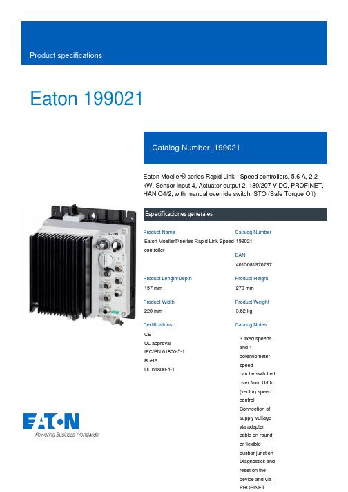
Eaton 199021Eaton Moeller® series Rapid Link - Speed controllers, 5.6 A, 2.2 kW, Sensor input 4, Actuator output 2, 180/207 V DC, PROFINET, HAN Q4/2, with manual override switch, STO (Safe Torque Off)Especificaciones generalesEaton Moeller® series Rapid Link Speed controller1990214015081970797157 mm 270 mm 220 mm 3.62 kg CE UL approval IEC/EN 61800-5-1 RoHS UL 61800-5-1Product NameCatalog NumberEANProduct Length/Depth Product Height Product Width Product Weight Certifications Catalog Notes 3 fixed speeds and 1 potentiometer speedcan be switched over from U/f to (vector) speed control Connection of supply voltage via adapter cable on round or flexible busbar junction Diagnostics and reset on the device and via PROFINET480 VIs the panel builder's responsibility. The specifications for the switchgear must be observed.480 V AC, 3-phase400 V AC, 3-phaseMeets the product standard's requirements.2.2 kW500 VMeets the product standard's requirements.-40 °C380 VPC connectionKey switch position AUTOPTC thermistor monitoringControl unitKey switch position OFF/RESETManual override switchTwo sensor inputs through M12 sockets (max. 150 mA) for quick stop and interlocked manual operationInternal DC linkThermo-click with safe isolationIGBT inverterKey switch position HANDSelector switch (Positions: REV - OFF - FWD)2 Actuator outputs0 Hz200 %, IH, max. starting current (High Overload), For 2 seconds eaton-bus-adapter-rapidlink-speed-controller-dimensions-002.eps eaton-bus-adapter-rapidlink-speed-controller-dimensions-003.eps eaton-bus-adapter-rapidlink-speed-controller-dimensions-005.eps eaton-bus-adapter-rapidlink-speed-controller-dimensions-004.epsETN.RASP5-5421PNT-412R010S1.edzRapid Link 5 - brochureDA-SW-drivesConnectDA-SW-USB Driver DX-COM-STICK3-KITDA-SW-Driver DX-CBL-PC-3M0DA-SW-drivesConnect - installation helpDA-SW-USB Driver PC Cable DX-CBL-PC-1M5DA-SW-drivesConnect - InstallationshilfeMaterial handling applications - airports, warehouses and intra-logisticsDA-DC-00004184.pdfDA-DC-00004612.pdfDA-DC-00003964.pdfDA-DC-00004613.pdfIL034093ZUrasp5_v33.stpramo5_v33.dwgConfiguration to Rockwell PLC for Rapid LinkGeneration Change RA-SP to RASP5Generation change from RA-MO to RAMO 4.0Generation Change RASP4 to RASP5Generation change RAMO4 to RAMO5Generation change from RA-SP to RASP 4.0Mains voltage - max10.11 Short-circuit ratingRated operational voltage10.4 Clearances and creepage distancesOutput at quadratic load at rated output voltage - max Output voltage - max10.2.3.1 Verification of thermal stability of enclosures Ambient storage temperature - minMains voltage - minFitted with:Output frequency - minStarting current - max DibujoseCAD modelFolletosInformes de certificaciónInstrucciones de montaje mCAD modelNotas de aplicaciónevery 20 seconds, Power sectionRated conditional short-circuit current (Iq)10 kAAmbient operating temperature - max40 °CCommunication interfacePROFINET, optionalAssigned motor power at 115/120 V, 60 Hz, 1-phase3 HPOutput frequency - max500 HzSwitching frequency8 kHz, 4 - 32 kHz adjustable, fPWM, Power section, Main circuitFeaturesParameterization: KeypadParameterization: drivesConnect mobile (App) Parameterization: drivesConnectParameterization: FieldbusAmbient operating temperature - min-10 °CBraking current≤ 0.6 A (max. 6 A for 120 ms), Actuator for external motor brakeNumber of HW-interfaces (serial TTY)10.6 Incorporation of switching devices and componentsDoes not apply, since the entire switchgear needs to be evaluated.Nominal output current I2N5.6 A10.2.6 Mechanical impactDoes not apply, since the entire switchgear needs to be evaluated.10.3 Degree of protection of assembliesDoes not apply, since the entire switchgear needs to be evaluated.Product categorySpeed controllerRadio interference classC1: for conducted emissions onlyC2, C3: depending on the motor cable length, the connected load, and ambient conditions. External radio interference suppression filters (optional) may be necessary.Heat dissipation capacity Pdiss0 WRated control voltage (Uc)180/207 V DC (external brake 50/60 Hz)24 V DC (-15 %/+20 %, external via AS-Interface® plug)Assigned motor power at 460/480 V, 60 Hz, 3-phase3 HPNumber of HW-interfaces (RS-422)Mains current distortion120 %ProtocolPROFINET IO10.9.2 Power-frequency electric strengthIs the panel builder's responsibility.Overvoltage categoryIIIDegree of protectionIP65NEMA 12Ambient storage temperature - max70 °CRated impulse withstand voltage (Uimp)2000 VConnectionPlug type: HAN Q4/2Overload currentAt 40 °CFor 60 s every 600 sFunctions3 fixed speeds1 potentiometer speedSTO (Safe Torque Off)For actuation of motors with mechanical brakeOutput at linear load at rated output voltage - max2.2 kWMains voltage tolerance380 - 480 V (-10 %/+10 %, at 50/60 Hz)Leakage current at ground IPE - max3.5 mAConverter typeU converter10.2.2 Corrosion resistanceMeets the product standard's requirements.Supply frequency50/60 Hz10.2.4 Resistance to ultra-violet (UV) radiationMeets the product standard's requirements.10.2.7 InscriptionsMeets the product standard's requirements.Shock resistance15 g, Mechanical, According to IEC/EN 60068-2-27, 11 ms, Half-sinusoidal shock 11 ms, 1000 shocks per shaftApplication in domestic and commercial area permittedYesNumber of inputs (analog)Number of phases (output)310.12 Electromagnetic compatibilityIs the panel builder's responsibility. The specifications for the switchgear must be observed.10.2.5 LiftingDoes not apply, since the entire switchgear needs to be evaluated.Number of HW-interfaces (RS-485)1Number of HW-interfaces (industrial ethernet)Efficiency98 % (η)System configuration typePhase-earthed AC supply systems are not permitted.AC voltageCenter-point earthed star network (TN-S network)10.8 Connections for external conductorsIs the panel builder's responsibility.ProtectionFinger and back-of-hand proof, Protection against direct contact (BGV A3, VBG4)Braking voltage280/207 V DC -15 % / +10 %, Actuator for external motor brakeApplication in industrial area permittedYesClimatic proofing< 95 %, no condensationIn accordance with IEC/EN 5017810.9.3 Impulse withstand voltageIs the panel builder's responsibility.Overload current IL at 150% overload8.4 AInput current ILN at 150% overload5.3 ANumber of HW-interfaces (RS-232)Number of inputs (digital)4Current limitationAdjustable, motor, main circuit0.5 - 5.6 A, motor, main circuitCable lengthC3 ≤ 25 m, maximum motor cable lengthC1 ≤ 1 m, maximum motor cable lengthC2 ≤ 5 m, maximum motor cable length10.5 Protection against electric shockDoes not apply, since the entire switchgear needs to be evaluated.Mounting positionVerticalMains switch-on frequencyMaximum of one time every 60 seconds10.13 Mechanical functionThe device meets the requirements, provided the information in the instruction leaflet (IL) is observed.10.9.4 Testing of enclosures made of insulating materialIs the panel builder's responsibility.Heat dissipation per pole, current-dependent Pvid0 WElectromagnetic compatibility1st and 2nd environments (according to EN 61800-3)Resolution0.1 Hz (Frequency resolution, setpoint value)Assigned motor power at 460/480 V, 60 Hz3 HPRelative symmetric net voltage tolerance10 %Rated operational current (Ie)5.6 A at 150% overload (at an operating frequency of 8 kHz and an ambient air temperature of +40 °C)Number of outputs (analog)Rated operational power at 380/400 V, 50 Hz, 3-phase2.2 kWNumber of HW-interfaces (USB)Operating modePM and LSPM motorsSynchronous reluctance motorsBLDC motorsSensorless vector control (SLV)U/f controlRated frequency - min45 HzDelay time< 10 ms, Off-delay< 10 ms, On-delayNumber of outputs (digital)2Power consumption58 W10.2.3.2 Verification of resistance of insulating materials to normal heatMeets the product standard's requirements.10.2.3.3 Resist. of insul. mat. to abnormal heat/fire by internal elect. effectsMeets the product standard's requirements.Number of HW-interfaces (other)Rated frequency - max66 HzVibrationResistance: 10 - 150 Hz, Oscillation frequencyResistance: 57 Hz, Amplitude transition frequency on accelerationResistance: 6 Hz, Amplitude 0.15 mmResistance: According to IEC/EN 60068-2-6Short-circuit protection (external output circuits)Type 1 coordination via the power bus' feeder unit, Main circuit10.7 Internal electrical circuits and connectionsIs the panel builder's responsibility.Braking torque≤ 30 % (I/Ie)Adjustable to 100 % (I/Ie), DC - Main circuitRelative symmetric net frequency tolerance10 %10.10 Temperature riseThe panel builder is responsible for the temperature rise calculation. Eaton will provide heat dissipation data for the devices.Number of HW-interfaces (parallel)Assigned motor power at 230/240 V, 60 Hz, 1-phase3 HPInterfacesMax. total power consumption from AS-Interface® power supply unit (30 V): 250 mANumber of slave addresses: 31 (AS-Interface®) Specification: S-7.4 (AS-Interface®)Eaton Corporation plc Eaton House30 Pembroke Road Dublin 4, Ireland © 2023 Eaton. All Rights Reserved. Eaton is a registered trademark.All other trademarks areproperty of their respectiveowners./socialmedia336.6 W at 25% current and 0% speed 38.1 W at 25% current and 50% speed 42 W at 50% current and 0% speed 42.5 W at 50% current and 90% speed 44.2 W at 50% current and 50% speed 55.9 W at 100% current and 0% speed 58.3 W at 100% current and 90% speed 60.4 W at 100% current and 50% speed 2Above 1000 m with 1 % performance reduction per 100 m Max. 2000 mNumber of phases (input)Heat dissipation at current/speed Number of interfaces (PROFINET)Altitude。
(整理)SMD1812系列保险丝.

SMD1812系列保险丝一,陆海简介;台湾陆海电子股份有限公司原为陆海股份有限公司之电子事业,1997年创立于美国加州Fr e mo n t,自创立以来一直专注于过电流保护组件之开发是一家集研发,生产与销售为一体的专业PPTC多次性保险丝制造厂商,基于提供高质量、稳定安全的过电流保护产品的坚持,以及符合世界先进大厂严格的品管要求,多年来陆海除了持续投入巨额研发预算,邀集多位海内外优秀人才主持研发部门,并且不遗余力的投入品管人员教育训练,建立严谨的品管流程,致力于推出更安全、更符合市场需求的过电流保护产品。
台湾陆海电子股份有限公司二,产品分类;贴片型(SMD)SMD0603、SMD0805、nSMD、SMD1210、mSMD、SMD2018、SMD2920系列插脚型(RLD/R-Type)R16(16v)、R30(30v)、R60(60v)、R72(72v)、C250 (250v)、C600(600v)系列电池保护片(ALD/S-Type)VLD、MHD、HPD系列三,工作原理;自恢复保险丝的动作原理是一种能量的动态平衡,流过自恢复保险丝系列元件的电流由于自恢复保险丝系列的关系产生热量,产生的热全部或部分散发到环境中,而没有散发出去的热便会提高自恢复保险丝系列元件的温度。
正常工作时的温度较低,产生的热和散发的热达到平衡。
自恢复保险丝系列元件处于低阻状态,自恢复保险丝系列不动作,当流过自恢复保险丝系列元件的电流增加或环境温度升高,但如果达到产生的热和散发的热的平衡时,自恢复保险丝系列仍不动作。
当电流或环境温度再提高时,自恢复保险丝系列会达到较高的温度。
若此时电流或环境温度继续再增加,产生的热量会大于散发出去的热量,使得自恢复保险丝系列元件温度骤增,在此阶段,很小的温度变化会造成阻值的大幅提高,这时自恢复保险丝系列元件处于高阻保护状态,阻抗的增加限制了电流,电流在很短时间内急剧下降,从而保护电路设备免受损坏,只要施加的电压所产生的热量足够自恢复保险丝系列元件散发出的热量,处于变化状态下的自恢复保险丝系列元件便可以一直处于动作状态(高阻)。
tm1812

一、 概述TM1812是12通道LED(发光二极管显示器)驱动控制专用电路,内部集成有MCU 数字接口、数据锁存器、LED 高压驱动等电路。
通过外围 MCU控制实现该芯片的单独辉度、级联控制实现户外大屏、护栏管、幻彩灯条的彩色点阵发光控制。
本产品性能优良,质量可靠。
采用SOP16的封装形式。
二、 特性说明z采用高压功率CMOS工艺z输出端口耐压24Vz芯片工作电压支持5V~24Vz内置稳压电路z辉度调节电路(256级辉度可调)z单线串行级联接口,通过一根信号线完成数据的接收与解码z振荡方式:内置双RC 振荡并根据数据线上信号进行时钟同步z内置上电复位电路z PWM控制端能够实现256级调节,扫描频率不低于400hz/sz当刷新速率为30帧/s时,级联灯个数不小于1080点z数据发送速度800Kbpsz封装形式:SOP16三、管脚定义:VDD DOUT 4OUTR 4OUTG 4OUTB 3OUTR 3OUTG 3OUTBDIN1OUTR 1OUTG 1OUTB 2OUTR 2OUTG 2OUTB GND四、管脚功能定义:管脚号 符号 管脚名称 说明16 DIN 数据输入 显示数据输入2 DOUT 数据输出 显示数据级联输出15 1OUTR LED驱动输出 第1路 Red PWM控制输出14 1OUTG LED驱动输出 第1路 Green PWM控制输出13 1OUTB LED驱动输出 第1路 Blue PWM控制输出12 2OUTR LED驱动输出 第2路 Red PWM控制输出11 2OUTG LED驱动输出 第2路 Green PWM控制输出10 2OUTB LED驱动输出 第2路 Blue PWM控制输出6 3OUTR LED驱动输出 第3路 Red PWM控制输出7 3OUTG LED驱动输出 第3路 Green PWM控制输出8 3OUTB LED驱动输出 第3路 Blue PWM控制输出3 4OUTR LED驱动输出 第4路 Red PWM控制输出4 4OUTG LED驱动输出 第4路 Green PWM控制输出5 4OUTB LED驱动输出 第4路 Blue PWM控制输出1 VDD 逻辑电源 6V±10%9 GND 逻辑地 接系统地五、 电气参数:极限参数(Ta = 25℃, Vss = 0 V)参数 符号 范围 单位 逻辑电源电压 VDD +6.0 ~+7.0 V输出端口耐压 VOUTx 24 V逻辑输入电压 VI1 -0.5 ~ VDD + 0.5 VLED驱动输出电流 IO1 80 mA 功率损耗 PD 400 mW工作温度 Topt -40 ~ +80 ℃储存温度 Tstg -65 ~+150 ℃正常工作范围(Ta = -20 ~ +70℃,Vss = 0 V)参数 符号 最小 典型 最大 单位 测试条件逻辑电源电压 VDD 6 V - 高电平输入电压 VIH 0.7 VDD - VDD V - 低电平输入电压 VIL 0 - 0.3 VDD V -电气特性(Ta=-20~+70℃,VDD=4.5~5.5V,Vss=0V)参数 符号 最小 典型最大 单位 测试条件低电平输出电流 IOL1 80 140 - mA OUTR/OUTG/OUTB Vo=0.3V低电平输出电流 Idout 10 - - mA VO = 0.4V,DOUT 输入电流 II - - ±1 μA VI = VDD / VSS 高电平输入电压 VIH 0.7 VDD- V DIN低电平输入电压 VIL - - 0.3 VDD V DIN 滞后电压 VH - 0.35- V DIN 动态电流损耗 IDDdyn - - 1 mA 无负载,显示关 消耗功率 PD 250 mW (Ta=25°C) 热阻值Rth(j-a) 79.2 190 °C/W开关特性(Ta = -20 ~ +70℃,VDD = 4.5 ~ 5.5 V)参数 符号 最小典型最大单位测试条件Fosc1 - 400 - KHz / 振荡频率Fosc2 - 800 - KHz /tPLZ - - 300 ns DIN → DOUT传输延迟时间tPZL - - 100 ns CL = 15pF, RL = 10K Ω 下降时间 TTHZ - - 120 μs CL = 300pF, OUTR/OUTG/OUTB 数据传输率 Fmax 400 - - Kbps占空比50%输入电容 CI - - 15 pF -六、功能描叙:芯片采用单线通讯方式,采用归零码的方式发送信号。
飞思卡尔扩展适合消费电子和工业应用的智能触摸传感选件
飞思卡尔扩展适合消费电子和工业应用的智能触摸传感选件
佚名
【期刊名称】《电子技术应用》
【年(卷),期】2009(035)011
【摘要】2009年10月12日,德州奥斯汀——飞思卡尔半导体不断扩展其广泛
的触摸传感解决方案系列,新增了MPR121超低功率电容传感器和触摸传感软件(TSS)套件,能够兼容飞思卡尔300多种8位微控制器(MCU)。
使用这种新
型产品,飞思卡尔能够让客户为他们广泛的消费电子和工业应用界面设计选择最适当的产品。
【总页数】1页(P17)
【正文语种】中文
【相关文献】
1.飞思卡尔扩展MEMS1-2-3轴传感器满足消费电子市场 [J], 彭湃
2.飞思卡尔90nm ColdFire+混合信号微控制器解决方案加快设计创新下一代ColdFire MCU提供针对消费电子和工业应用的FlexMemory和超低功耗特性 [J],
3.飞思卡尔针对工业和汽车设计扩展连接、“智能触摸”和安全选件 [J],
4.飞思卡尔针对工业和汽车设计扩展连接、“智能触摸”和安全选件 [J],
5.宏基新款DisplayPlus显示器选配飞思卡尔IC飞思卡尔将在国际消费电子展(CES)上演示宏基智能显示器 [J],
因版权原因,仅展示原文概要,查看原文内容请购买。
- 1、下载文档前请自行甄别文档内容的完整性,平台不提供额外的编辑、内容补充、找答案等附加服务。
- 2、"仅部分预览"的文档,不可在线预览部分如存在完整性等问题,可反馈申请退款(可完整预览的文档不适用该条件!)。
- 3、如文档侵犯您的权益,请联系客服反馈,我们会尽快为您处理(人工客服工作时间:9:00-18:30)。
Document Number: 34044For technical questions, contact: magnetics@Revision: 23-Feb-111Wirewound, Surface Mount, Molded InductorsIMC-1812Vishay DaleNote(1)Rated DC current based on the maximum temperature rise, not to exceed 40 °C at + 85 °C ambient FEATURES•Molded construction provides superior strength and moisture resistance•Tape and reel packaging for automatic handling, 2000/reel, EIA-481•Printed marking•Compatible with vapor phase and infrared reflow soldering•Compliant to RoHS Directive 2002/95/ECELECTRICAL SPECIFICATIONSInductance Range: 0.010 μH to 1000 μHInductance Tolerance: ± 20 % for 0.010 μH to 0.39 μH ± 10 % for 0.47 μH to 1000 μH standard ± 10 %, ± 5 %, ± 3 % availableOperating Temperature: - 55 °C to + 125 °CCoilform Material: Non-magnetic for 0.010 μH to 0.82 μH Powdered iron for 1.0 μH to 120 μH Ferrite for 150 μH to 1000 μHTEST EQUIPMENT•H/P 4342A Q meter with Vishay Dale test fixture or equivalent•H/P 4191A RF impedance analyzer (for SRF measurements)•Wheatstone bridgeNote(2)Recommended minimum spacing between componentsSTANDARD ELECTRICAL SPECIFICATIONSIND.(μH)TOL.TEST FREQ.(MHz)QMIN.SRFMIN.(MHz)DCR MAX.( )RATED DC CURRENT (mA) (1)L & Q0.010± 20 %50.05010000.204500.012± 20 %50.05010000.204500.018± 20 %50.05010000.204500.022± 20 %50.05010000.204500.027± 20 %50.05010000.204500.033± 20 %50.05010000.304500.039± 20 %50.05010000.304500.047± 20 %50.05010000.304500.056± 20 %50.0409000.354500.068± 20 %50.0408000.354500.082± 20 %50.0407000.404500.10± 20 %25.2306500.324500.12± 20 %25.2306000.304500.15± 20 %25.2305000.304500.18± 20 %25.2304000.354500.22± 20 %25.2303500.404500.27± 20 %25.2303000.454500.33± 20 %25.2302500.554300.39± 20 %25.2302200.703800.47± 10 %25.2301900.803550.56± 10 %25.230170 1.202850.68± 10 %25.230150 1.402700.82± 10 %25.230140 1.602501.0± 10 %7.96501000.504501.2± 10 %7.965080.00.554301.5± 10 %7.965070.00.604101.8± 10 %7.965060.00.653902.2± 10 %7.965055.00.703802.7± 10 %7.965050.00.753703.3± 10 %7.965045.00.803553.9± 10 %7.965040.00.903304.7± 10 %7.965035.0 1.003155.6± 10 %7.965033.0 1.103006.8± 10 %7.965027.0 1.202858.2± 10 %7.965025.0 1.4027010.0± 10 % 2.525020.0 1.6025012.0± 10 % 2.525018.0 2.0022515.0± 10 % 2.525017.0 2.5020018.0± 10 % 2.525015.0 2.8019022.0± 10 % 2.525013.0 3.2018027.0± 10 % 2.525012.0 3.6017033.0± 10 % 2.525011.0 4.0016039.0± 10 % 2.525011.0 4.5015047.0± 10 % 2.525010.0 5.0014056.0± 10 % 2.52509.0 5.5013568.0± 10 % 2.52509.0 6.0013082.0± 10 % 2.52508.07.00120100.0± 10 %0.79408.08.00110120.0± 10 %0.7940 6.08.00110150.0± 10 %0.7940 5.09.00105180.0± 10 %0.7940 5.09.50102220.0± 10 %0.7940 4.010.0100270.0± 10 %0.7940 4.012.092330.0± 10 %0.7940 3.514.085390.0± 10 %0.7940 3.016.080470.0± 10 %0.7940 3.026.062560.0± 10 %0.7930 3.030.050680.0± 10 %0.7930 3.030.050820.0± 10 %0.7930 2.535.0301000.0± 10 %0.2530 2.540.030PART MARKING- Vishay Dale- Inductance value - Date code For technical questions, contact: magnetics@Document Number: 340442Revision: 23-Feb-11IMC-1812Vishay DaleWirewound, Surface Mount, Molded InductorsDESCRIPTIONIMC-181210 μH± 10 %ERe3MODELINDUCTANCE VALUEINDUCTANCE TOLERANCEPACKAGE CODEJEDEC LEAD (Pb)-FREE STANDARDGLOBAL PART NUMBERIM C1812ER100K PRODUCT FAMILYSIZEPACKAGE CODEINDUCTANCEVALUETOL.Legal Disclaimer Notice VishayDisclaimerALL PRODU CT, PRODU CT SPECIFICATIONS AND DATA ARE SU BJECT TO CHANGE WITHOU T NOTICE TO IMPROVE RELIABILITY, FUNCTION OR DESIGN OR OTHERWISE.Vishay Intertechnology, Inc., its affiliates, agents, and employees, and all persons acting on its or their behalf (collectively,“Vishay”), disclaim any and all liability for any errors, inaccuracies or incompleteness contained in any datasheet or in any other disclosure relating to any product.Vishay makes no warranty, representation or guarantee regarding the suitability of the products for any particular purpose or the continuing production of any product. To the maximum extent permitted by applicable law, Vishay disclaims (i) any and all liability arising out of the application or use of any product, (ii) any and all liability, including without limitation special, consequential or incidental damages, and (iii) any and all implied warranties, including warranties of fitness for particular purpose, non-infringement and merchantability.Statements regarding the suitability of products for certain types of applications are based on Vishay’s knowledge of typical requirements that are often placed on Vishay products in generic applications. Such statements are not binding statements about the suitability of products for a particular application. It is the customer’s responsibility to validate that a particular product with the properties described in the product specification is suitable for use in a particular application. Parameters provided in datasheets and/or specifications may vary in different applications and performance may vary over time. All operating parameters, including typical parameters, must be validated for each customer application by the customer’s technical experts. Product specifications do not expand or otherwise modify Vishay’s terms and conditions of purchase, including but not limited to the warranty expressed therein.Except as expressly indicated in writing, Vishay products are not designed for use in medical, life-saving, or life-sustaining applications or for any other application in which the failure of the Vishay product could result in personal injury or death. Customers using or selling Vishay products not expressly indicated for use in such applications do so at their own risk and agree to fully indemnify and hold Vishay and its distributors harmless from and against any and all claims, liabilities, expenses and damages arising or resulting in connection with such use or sale, including attorneys fees, even if such claim alleges that Vishay or its distributor was negligent regarding the design or manufacture of the part. Please contact authorized Vishay personnel to obtain written terms and conditions regarding products designed for such applications.No license, express or implied, by estoppel or otherwise, to any intellectual property rights is granted by this document or by any conduct of Vishay. Product names and markings noted herein may be trademarks of their respective owners.Material Category PolicyVishay Intertechnology, Inc. hereb y certifies that all its products that are identified as RoHS-Compliant fulfill the definitions and restrictions defined under Directive 2011/65/EU of The European Parliament and of the Council of June 8, 2011 on the restriction of the use of certain hazardous substances in electrical and electronic equipment (EEE) - recast, unless otherwise specified as non-compliant.Please note that some Vishay documentation may still make reference to RoHS Directive 2002/95/EC. We confirm that all the products identified as being compliant to Directive 2002/95/EC conform to Directive 2011/65/EU.Revision: 12-Mar-121Document Number: 91000分销商库存信息:VISHAYIMC1812ESR47K IMC1812ESR56K IMC1812ESR68K IMC1812ESR82K IMC1812EUR82K IMC1812RQR47K IMC1812RQR56K IMC1812RQR68K IMC1812RQR82K IMC1812RWR82K IMC1812ES12NM IMC1812ES18NM IMC1812ES22NM IMC1812ES27NM IMC1812ES33NM IMC1812ES39NM IMC1812ES47NM IMC1812ES56NM IMC1812ES68NM IMC1812ES82NM IMC1812ESR10M IMC1812ESR15M IMC1812ESR18M IMC1812ESR22M IMC1812ESR27M IMC1812ESR33M IMC1812ESR39M IMC1812RQ12NM IMC1812RQ18NM IMC1812RQ22NM IMC1812RQ27NM IMC1812RQ33NM IMC1812RQ39NM IMC1812RQ47NM IMC1812RQ56NM IMC1812RQ68NM IMC1812RQ82NM IMC1812RQR10M IMC1812RQR15M IMC1812RQR18M IMC1812RQR22M IMC1812RQR27M IMC1812RQR33M IMC1812RQR39M IMC1812ES68NK IMC1812ES82NK IMC1812ESR10K IMC1812ESR12K IMC1812ESR15K IMC1812ESR18K IMC1812ESR22K IMC1812ESR27K IMC1812ESR33K IMC1812ESR39K IMC1812RQ68NK IMC1812RQ82NK IMC1812RQR10K IMC1812RQR12K IMC1812RQR15K IMC1812RQR18K IMC1812RQR22K IMC1812RQR27K IMC1812RQR33K IMC1812RQR39K IMC1812ESR22J IMC1812ESR33J IMC1812ESR39J IMC1812ESR47J IMC1812ESR56J IMC1812ESR68J IMC1812ESR82J IMC1812RQR22J IMC1812RQR33J IMC1812RQR39J IMC1812RQR47J IMC1812RQR56J IMC1812RQR68J IMC1812RQR82J IMC1812ES100K IMC1812ES1R0K IMC1812ES1R2K IMC1812ES1R5K IMC1812ES1R8K IMC1812ES2R2K IMC1812ES2R7K IMC1812ES3R3K IMC1812ES3R9K IMC1812ES4R7K IMC1812ES5R6K IMC1812ES6R8K IMC1812ES8R2K IMC1812EU100K IMC1812EU8R2K IMC1812RL100K IMC1812RQ100K IMC1812RQ1R0K IMC1812RQ1R2K IMC1812RQ1R5K IMC1812RQ1R8K IMC1812RQ2R2K IMC1812RQ2R7K IMC1812RQ3R3K IMC1812RQ3R9K IMC1812RQ4R7K IMC1812RQ5R6K IMC1812RQ6R8K IMC1812RQ8R2K IMC1812RW100K IMC1812RW8R2K IMC1812ES120K IMC1812ES150K IMC1812ES180K IMC1812ES220K IMC1812ES270K IMC1812ES330K IMC1812ES390K IMC1812ES470K IMC1812RQ120K IMC1812RQ150K IMC1812RQ180K IMC1812RQ220K IMC1812RQ270K IMC1812RQ330K。
