ERX700-ERX1400软件升级学习笔记
inhand_device_networks_suitemicrologix_1400

帐号: chentao@ 密码:chentao123罗克韦尔MicroLogix 1400 PLC和3G路由器双工通信连接方式在实现PLC与3G路由器连接之前,首先测试PLC与PC机直连的连接方式。
1本地监控连接方式Rockwell PLC调试计算机PC1.1 PC端配置a> 安装软件针对罗克韦尔MicroLogix 1400 PLC。
罗克韦尔对其有特定的编程软件RSLogix 500 。
实现PC端对PLC的编程调试工作只需要安装“必选步骤”即可。
图1-1依次安装“必选步骤”下的所有项目安装,如图1-2图1-2注意:安装完毕后请退出,并重新启动计算机,使相应的服务全部生效。
b> 添加硬件在添加硬件之前,需要首先确定被控PLC的IP地址,如果客户没有要求,可以随意设置,若客户对PLC IP地址有要求,那么设定成客户所需要的IP。
本手册将PLC IP地址设置如下:IP地址:192.168.255.100;子网掩码为:255.255.255.0;默认网关为:192.168.255.1在进行编程调试之前,首先需要配置连接通道:单机“开始菜单”选择目录下的连接公工具如下图图1-3在这里我们使用“RSLinkx Classic”连接工具。
双击打开,获得如图1-4界面:点击通讯—配置驱动程序,弹出如图1-5所示对话框图1-4在“可用的驱动程序类型”中选择Ethernet devices然后单机“新增”弹出如图1-6所示对话框图1-5输入新驱动名称,单击确定之后在弹出的对话框中输入目标PLC的IP地址,如图1-7图1-6图1-7点击确定,到此完成了新硬件设备的添加。
依次关闭对话框。
退回到如图1-4所示界面。
点击如图1-8所示RSWho按钮,在PLC基本配置完成后,之前建立的硬件就会显示在资源管理器页面中。
图1-81.2 PLC端配置在PLC面板中。
初始画面为各个输入输出节点的状态,点击”ESC”按钮---按向下按钮,选择”Advanced Set”选项,点击“OK”---选择”ENET Cfg”选项,选择”IP Address”输入密码(初始密码为空)点击”OK”,选择”Stati”模式,点击”OK”即可对PLC进行本地IP设置。
Erx配置方法文档

Erx配置方法下面以用ERX700/1400,配合SIEMENS XPRESSLINK 组网时较为常用的B-RAS(Broadband-Remote Acess Server) 功能为例,简单介绍一下ERX端的配置方法,其中有许多命令是配置ERX路由器通用的。
详细的ERX CLI命令使用方法及命令全集可参看相关ERX手册:ERX Configuration Guide Vol. 1ERX Configuration Guide Vol. 2ERX Command Reference GuideERX-0-2-D0>进入Privileged Exec 模式ERX-0-2-D0>enableERX-0-2-D0#进入Global configuration 模式ERX-0-2-D0#configure terminalEnter configuration commands, one per line. End with CNTL/Z.ERX-0-2-D0(config)#给SRP所在10/100BASE-T接口配置IP地址ERX-0-2-D0(config)#interface FastEthernet slotnumber / 0ERX-0-2-D0(config-if)#ip address 172.17.1.1 255.255.255.0ERX-0-2-D0(config-if)#exitERX-0-2-D0#激活telnet访问功能(telnet server),并设置密码ERX-0-2-D0(config)#line vty 0 4ERX-0-2-D0(config-line)# loginERX-0-2-D0(config-line)# passwd telnetpasswordERX-0-2-D0(config-line)#exitERX-0-2-D0(config)#设置enable密码ERX-0-2-D0(config)#enable password enablepassword给ERX改一个有标志意义的名字ERX-0-2-D0(config)#hostname shangsha1400Shangsha1400(config)#配置B-RAS的licenseshangsha1400(config)#license b-ras DeMoNOTICE: The Subscriber Management Feature Pack software installed on thissystem is licensed to support a specific number of simultaneous xDSL users. Configuration or operational support for more concurrent users than what has been purchased is in direct violation of the product license agreement.Proceed with 'license b-ras' command? [confirm] press <enter> license for 100 subscribers configured.配置”loopback 0”接口的ip地址ERX-0-2-D0(config)#interface loopback 0ERX-0-2-D0(config-if)#ip address 192.168.1.1 255.255.255.0ERX-0-2-D0(config-if)#exitERX-0-2-D0#配置接口的profilechangsha1400(config)#profile xldchangsha1400(config-profile)#ip access-routeschangsha1400(config-profile)#exitchangsha1400(config)#在ERX fast ethernet 接口上配置pppoe/vlan3-0-0版之前:changsha1400(config)#int f9/1changsha1400(config-if)#enc vlanchangsha1400(config-if)#int f9/1.1changsha1400(config-if)#vlan id yourvlanidchangsha1400(config-if)#enc pppoechangsha1400(config-if)#int f9/1.1.1changsha1400(config-if)#enc pppchangsha1400(config-if)#ppp auth chapchangsha1400(config-if)#profile x ld3-0-0版之后:changsha1400(config)#int f9/1changsha1400(config-if)#enc vlanchangsha1400(config-if)#int f9/1.1changsha1400(config-if)#vlan id yourvlanidchangsha1400(config-if)#pppoechangsha1400(config-if)#exitchangsha1400(config)#pppoe subinterface f9/1.1.1changsha1400(config-if)#enc pppchangsha1400(config-if)#ppp auth chapchangsha1400(config-if)#profile x ld在ERX fast ethernet 接口上配置pppoe(无VLAN)3-0-0版之前:changsha1400(config)#int f9/1changsha1400(config-if)int f9/1.1changsha1400(config-if)#ip addr x.x.x.x m.m.m.m changsha1400(config-if)#int f9/1.2changsha1400(config-if)#enc pppoechangsha1400(config-if)#int f9/1.1.1changsha1400(config-if)#enc pppchangsha1400(config-if)#ppp auth chapchangsha1400(config-if)#profile x ld3-0-0版之后:changsha1400(config)#int f9/1changsha1400(config-if)#ip addr x.x.x.x m.m.m.m changsha1400(config-if)#pppoechangsha1400(config-if)#exitchangsha1400(config)#pppoe subinterface f9/1.1 changsha1400(config-if)#enc pppchangsha1400(config-if)#ppp auth chapchangsha1400(config-if)#profile x ld在ERX ATM接口上配置pppoechangsha1400(config)#int a1/0changsha1400(config-if)#int a1/0.1changsha1400(config-if)#atm pvc 100 10 100 aal5snap changsha1400(config-if)#enc pppoechangsha1400(config-if)#int atm 1/0.1.1changsha1400(config-if)#enc pppchangsha1400(config-if)#ppp auth chapchangsha1400(config-if)#profile x ldchangsha1400(config-if)#exit在ERX ATM接口上配置pppoachangsha1400(config)#int a1/0changsha1400(config-if)#int a1/0.2changsha1400(config-if)#atm pvc 101 10 101 aal5snap changsha1400(config-if)#enc pppchangsha1400(config-if)#ppp auth chapchangsha1400(config-if)#profile x ldchangsha1400(config-if)#exitchangsha1400(config)#配置ip pool,用来给ppp播号用户动态分配ip地址changsha1400(config)#ip local pool erxpool 202.102.1.1 202.102.1.254为拨号用户配置DNS地址changsha1400(config)#aaa dns primary primary-dns-ip-addresschangsha1400(config)#aaa dns secondary secondary-dns-ip-address配置一条静态路由changsha1400(config)#ip route 0.0.0.0 0.0.0.0 202.102.2.1若不需要做domain map(域名匹配)changsha1400(config)#aaa domain-map none default loop 0若需要做domain map(域名匹配)changsha1400(config)#aaa domain-map default default loop 0——设置名为default的域名为缺省。
erx1440维护手册

ERX1400维护手册目录1口令配置 (3)2宽带接入配置 (5)2.1关键性基本配置 (6)2.1.1配置一个LOOPBACK端口作为拨号端口的参考端口 (6)2.1.2配置拨号用户地址池 (6)2.1.3配置用户地址分配为本地分配 (6)2.1.4配置RADIUS Server的相关参数 (6)2.1.5PROFILE配置 (7)2.1.6Domain map配置 (8)2.2上连GE口配置与局域网PPP O E接入配置 (8)2.3华为IP上行DSLAM用户数据配置 (9)2.3.1基本业务用户数据配置 (9)2.3.2专线用户数据配置 (10)2.4ADSL拨号用户配置 (10)2.5ADSL专线用户的配置 (11)3系统管理 (12)3.1ERX的配置备份 (12)3.2ERX重起选项 (13)3.2.1关电重启或者关机 (13)3.2.2立即启动 (13)3.2.3定时重起 (13)3.2.4在一定时间后重起 (14)3.2.5重新启动特定的模块 (14)3.3ERX系统升级 (14)3.4如何从系统文件破坏的FLASH恢复启动文件 (15)3.5SRP RESET 按钮的功能 (16)3.6特权模式密码恢复 (16)3.7CONSOLE口密码的恢复 (16)4常用的PPPOE的排错命令 (17)4.1.1系统的常用命令 (18)5常见故障分析 (19)5.1安装时出现的问题 (19)5.1.1上连时与城域网交换机不通 (20)5.1.2下联与ATM交换机的配合 (20)5.1.3硬件告警 (20)5.2联调及维护时出现的问题——用户不能上网 (21)5.2.1找不到BRAS (21)5.2.2能找到BRAS,不能通过验证 (21)5.2.3能找到BRAS,能通过验证,不能拿到地址 (22)5.2.4能找到BRAS,能通过验证,能拿到地址,但是不能ping通任何地方 (22)第 1 页Unisphere Networks5.2.5能找到BRAS,能通过验证,能拿到地址,能ping通任何地方,但是不能下载大文件,也不能打开网页 (22)6其他 (22)第 2 页Unisphere Networks1口令配置在这一节将讲述如何在全局配置模式下配置PASSWORD和SECRET,用来阻止非法用户进入特权模式。
ERX 700 1400用户手册

BISC/国际交换ERX简明用户手册Version 1-0-7北京国际交换系统有限公司服务部2013-09-09ERX简明用户手册北京国际交换系统有限公司(此页空白)北京国际交换系统有限公司ERX简明用户手册目录概述 (1)第一章硬件介绍 (2)1.ERX各模块介绍 (2)1.1 交换路由处理模块(SRP Module) (3)1.2 交换路由处理接口模块(SRP I/O Module) (4)1.3 线路模块(Line Module) (5)1.4 线路接口模块(Line I/O Module) (6)2.故障处理 (7)2.1 模块上指示灯的含义 (7)2.2 常见告警处理 (8)3.ERX的启动过程 (9)第二章B-RAS配置介绍 (10)1.共有设置 (10)1.1 认证(RASIUS)属性 (10)1.2 RADIUS Server的设置 (10)1.3 配置IP Pool (11)1.4 为PPP用户配置DNS (11)1.5 配置loopback接口 (11)2.ATM Routed 1483 接口设置 (12)2.1 为每一用户划分独立的子网 (12)2.2 全部用户为一个子网(使用ip unnumbered接口) (12)3.ATM Bridge 1483 接口设置 (13)3.1 为每一用户划分独立的子网 (13)3.2 全部用户为一个子网(使用ip unnumbered接口) (13)4.ATM PPPOA 接口设置 (14)5.ATM PPPOE 接口设置 (14)6.未划分VLAN的Ethernet PPPOE接口设置 (15)ERX简明用户手册北京国际交换系统有限公司7.划分VLAN的Ethernet PPPOE接口设置 (15)8.Ethernet上的静态IP地址用户接口设置 (15)8.1为每一用户划分独立的子网 (16)8.2 全部用户为一个子网(使用ip unnumbered接口) (16)9.Profile与动态接口设置 (16)9.1 设置PPP用户域名匹配 (17)9.2 动态IP接口的实现 (17)9.3 动态PPPOA与PPPOE接口的实现 (18)第三章设备维护 (20)1. 常用维护命令 (20)1.1 检查系统状态 (20)1.2 检查端口流量 (21)1.3 密码设置 (22)1.4 保存与恢复系统配置 (23)2. 安装系统软件 (23)3. ERX log功能的使用 (24)DHCP Configure (27)第四章技术支持 (278)北京国际交换系统有限公司ERX简明用户手册概述本文档是对JuniperNetworks ERX700/1400路由器/宽带接入服务器配置维护的简要说明。
ERX700ERX1400配置及故障诊断2
ERX700/ERX1400配置及故障诊断(2)2 配置部分2.1 拨号配置(出现NO SERVICE时的处理)atm 拨号端口典型配置:interface atm 12/0atm clock internal chassisatm vc-per-vp 4096atm oam flush!interface atm 12/0.332 point-to-pointatm pvc 332 3 32 aal5snap 0 0 0encapsulation pppoepppoe acName wenzhou!interface atm 12/0.332.1encapsulation pppppp authentication papprofile any pppoe以太口拨号端口典型配置:interface gigabitEthernet 8/0.4vlan id 4pppoe!pppoe subinterface gigabitEthernet 8/0.4.1encapsulation pppppp authentication papprofile any pppoe以下命令可以观察拨号端口是否工作正常:show pppoe interface atm 5/1----列出所有atm5/1上的pppoe interface,正常情况下,只要该端口的物理链路和pvc状态是up的,那么所有pppoe interface 的operational status 应当是up的。
SZ_ERX1400_LQF#show pppoe interface atm 3/1PPPoE interface atm 3/1.21101 is operStatusUpPPPoE interface atm 3/1.21102 is operStatusUpPPPoE interface atm 3/1.21103 is operStatusUpshow ppp interface gi3/1――――列出所有gi3/1上的ppp interface ,正常情况下,如果该端口有拨号用户在线则状态应为up,如果没有拨号用户在线状态为lowerdown。
ERX700ERX1400配置及故障诊断3

ERX700/ERX1400配置及故障诊断(3)2.3 MACRO的使用ERX提供该命令可以使得用户的拨号端口的创建可以批量自动完成。
在使用之前首先需要创建扩展名为.mac的script 文件。
以下是在以太端口(fa4/0和fa4/1)上配置拨号数据的script 文本:<# fa4 #>―――――――――――子程序名字<# vlanid:=962 #><# while vlanid<=964 #>――――第一组循环interface fa4/0.vlanidvlan id vlanidencap pppoeinterface fa4/0.vlanid.1encapsulation pppppp authentication papprofile any pppoe<# vlanid:=vlanid+1 #><# vlanid:=962 #><# while vlanid<=964 #>――――第二组循环interface fa4/1.vlanidvlan id vlanidencap pppoeinterface fa4/1.vlanid.1encapsulation pppppp authentication papprofile any pppoe<# vlanid:=vlanid+1 #><# endwhile #>每个.mac文件由一个或多个子程序组成,每个子程序可以由多个循环组成但是不能嵌套。
将该mac例如:fast.mac上传到erx,通过以下命令运行该script:macro test fast.mac fa4 ----------macro每次只能运行一个子程序test是一个关键字用于测试该script是否有语法错,如果没有macro会将执行结果输出到telnet窗口上。
JUNIPER (ERX)宽带接入服务器日常维护
JUNIPER (ERX)宽带接入服务器日常维护1.概述本文档主要介绍JUNIPER BRAS服务器ERX1400硬件/软件方面的日常维护,描述了BRAS在日常运行中可能出现的故障及解决方法。
本文档适合用JUNIPER产品-BAS的网络管理员,网络日常维护人员。
2.硬件介绍ERX1440配置的ERX1440机框具有14个槽位,系统路由及交换模块占用中间两个槽位,其余12个槽位可以配置不同类型的接口模块。
每一组接口模块有两部分组成:前卡为LINEMODULE线路模块,后卡为I/OMODULE I。
前卡负责数据包的查找及转发,后卡负责各种类型的物理端口连接。
ERX-1400的系统路由及交换模块 (SRP) 的交换能力为10Gbps全双工。
ERX-1400的路由及交换模块 (SRP) 在一台ERX上有两个,它们共享一块SRP的接口板 (SRP后板)。
SRP模块主要完成系统的路由学习/系统的数据线速交换/设备状态管理及完成系统软件配置。
SRP后板主要由CONSOLE端口及带外网管以太口和系统外部时钟接口等组成。
SRP同时会将一份系统软件及路由表下载到线路模块上。
ERX1400的SRP以热备份方式工作即一块SRP工作在PRIMARY状态下,另一块SRP工作在SLAVE状态下,当主用SRP出现故障时,备用SRP自动取得所有的系统控制。
ERX-1400的电源采用直流供电,一共有两路-48V输入,每一路要求30A,两路电源按负载均担方式工作。
ERX-1400的风扇系统在整个机框的顶部。
接口模块的工作状态: 每一组接口模块的前卡有三个指示灯---POWER/LINK/FAIL。
正常情况下只有POWER及LINK灯长亮 (绿色)。
如果FAIL灯长亮 (红色) ,表明该接口模块的前卡没有正常工作,需要进一步诊断。
3.常见故障及排除方法·Line card 工作异常现象:FAIL 灯长亮,ONLINE灯不亮解决措施:如果用命令SHOW HARDWARE 确认该模块一直处于“booting”状态,可以用RELOAD SLOT X 将该模块重启。
2012暑促培训Erazer X700有限揭秘版

德国第一PC品牌
1st place PC Advisor Awards 2010 in front of Acer, Dell and HP
终极装备 杀敌于无形
3档模式开关
5个可编程按键
4 种用户自定DPI 指示灯
15 个用户自定义功能
精准模式
手掌拖可前后调节
30g 可移动砝码
宇宙最强利器 来自联想中国
பைடு நூலகம்
霸气外观 领袖气质
80L超大外形 PC中的巨无霸 博派领袖变身设计 炫酷灯效 神秘冷光
超级装备 超强扩展
支持双显卡交火 最高可扩展至14T硬盘 最大支持32G内存
源自德国 品质缔造
2011年6月1日:联想集团今日宣布收购德国Medion Medion是德国知名品牌,在个人电脑、多媒体产品及消费电子等多领域具有领先地位 Erazer是德国Medion旗下高端游戏PC品牌 欧洲最具创新力品牌——IT产品&游戏产品领域
外星人入侵!
谁,能够守护我们的地球? 2012-07 Lenovo Erazer 降临!
联想 性能旗舰Erazer X700隆重登场
为地球而战
联想电脑性能旗舰
源自德国 血统高贵
德国设计 原装引进 欧洲第一战队专用装备 历史悠久 屡获大奖
骨灰硬件 极致性能
酷睿至尊 6核12线程 SSD Raid 0磁盘阵列 水冷设备 自由超频
热容量大,温度均衡
高效散热,极致静音
Erazer X700性能旗舰
前置3.5寸SATA热插拔硬盘扩展仓
ERX路由器功能说明

提 供 QoS/CoS
支 持
运营商级交换路由器必须能够集成并融合公共网 络入口的数以百计的用户并为他们提供必要的 QoS 支 持
用户设备
ERX 1400/700
边缘 核心
对每个数据包进行分 类并对其执行相关的 QoS 策 略
根据用户的业务规划将核 心带宽分配给每个用户
标记每个数据包使交 换机可以正确地对其 进行处理
ERX1400 ERX700
Any IP Path
网元
实际应用举例
•使用 使用ERX虚拟路由器简化网络结构 使用 虚拟路由器简化网络结构 •xDSL接入 接入---B-RAS 接入
现在ISP的网络结构 的网络结构 现在
EDGE LAN
IP PPP E1/E3
EDGE WAN
CORE
EDGE WAN
Redistribution
物 理 接 口 协 议 支 持
支持以下端口
• SONET
– IP/ATM/SONET 和 IP/PPP/SONET – Bellcore GR-253-CORE – SONET 或 SDH
•
帧中继
– DTE/DCE – LMI
• ATM
– – – – – LLC and VC mux AAL5 ILMI UBR 和 nrt-VBR OAM F5
现在xDSL的实施方案 的实施方案 现在
Consumer & Business Users (xDSL)
ERX focus
IP/PPP/ATM
ATM/FR Switch
Network Appliance
IP Router
Internet
IP/PPP/FR
EasyBuilder Pro软件版本更新说明说明书
软件版本:EasyBuilder Pro V6.07.01.496功能支持说明符合下列条件机器,需搭配使用此软件版本或更新的版本方可支持MPI功能。
机型序号开头(大于或等于)MT8051iE 2210xxxxxxMT8051iP2211xxxxxxMT8121iE2MT8150iE2 2301xxxxxxcMT-SVR-100 2212xxxxxx功能修正修正下述问题:1.刻度元件在特定情况时,绘制不完整。
2.元件不正确显示向量图的内部设置的颜色。
3.XY曲线图元件的参考线绘制不正确。
4.历史数据显示元件的文字预览颜色不正确。
通讯/驱动程序相关1.[BACnet/IP]MultiStateValue、BinaryValue支持RelinquishDefault地址。
2.[Mitsubishi FX5U]修正数据读取的问题。
3.[Siemens S7-1200/S7-1500 (Absolute Addressing) Ethernet]]修正于特定情况下字符串读取不完整的问题。
4.[Fuji SPH2000/3000 IEC Mode (Ethernet)][Fuji SPH2000/3000 Standard Mode (Ethernet)]支持使用通讯模块的通讯。
功能修正1.优化事件记录同步MS SQL的动作。
2.修正升级软件版本后发生的问题:部分设置错误、不显示、或档案无法开启或反编译等问题。
功能支持1.cMT3169X支持使用CAN Bus相关驱动程序(有硬件版本限制)。
功能修正1.修正下载工程档案时出现不正确的错误讯息的问题。
通讯/驱动程序相关1.[Mitsubishi FX3U/FX3G/FX3GA]修正cMT X系列机种偶有无法建立通讯的问题。
2.[Barcode Scanner CDC/POS Mode (USB)]新增驱动程序(部分机种适用并需搭配新版本OS)。
机型支援cMT-SVRX-920/922功能修正修正/处理下述问题2.字型Batang不能正常使用。
宽带接入服务器BAS及各厂家相关设备介绍-20020412-A

宽带接入服务器(BAS)及各厂家相应设备介绍拟制:丁健,尹启龙日期:审核:日期:审核:日期:批准:日期:修订记录深圳市华为技术有限公司目录第一章宽带接入服务器 BAS 总体介绍 51.1 宽带接入服务器的网络定位 51.2 宽带接入服务器的系统要求 51.2.1 硬件设计结构 51.2.2 接口类型和接入方式 61.2.3 接入数量 6 第二章各主要厂家 BAS 设备介绍71.1 Unisphere公司71.2 Nortel公司81.3 Redback公司101.4 华为公司121.4.1 产品定位121.4.2 产品主要功能和特点121.4.3 组网模型131.4.4 产品竞争能力分析151.5 各BAS设备的特性指标151.5.1 ERX700:151.5.2 Shasta5000:161.5.3 SMS10000:171.5.4 ISN8850:181.6 电总BAS设备的测试结果20宽带接入服务器(BAS)及各厂家相应设备介绍摘要:关键词:BASBAS:Broadband Acess Server——宽带接入服务器。
12第一章宽带接入服务器 BAS 总体介绍随着数据网络宽带化进程的加剧,以xDSL、HFC甚至光纤局域网为代表的广域网宽带接入技术迅猛发展,并已开始大规模地投入商用。
对于日益庞大,数目众多的宽带接入网络架构,如何更加有效、更加方便地实现网络统一管理,提供灵活多样的网络应用服务是摆在网络运营商面前很现实的问题。
1.1 宽带接入服务器的网络定位应该说,宽带接入服务器的推出在很大程度上是由于ADSL的大面积推广应用。
我们知道,以前ADSL要实现宽带接入网络业务通常是通过为每一用户的某一业务创建一条相应PVC连接,然后将这些数目众多的PVC直接终结在路由器上。
可以想象,这所带来的问题将是网络结构庞大,用户连接复杂,实际维护困难。
而且,这种接入网络结构主要以静态IP接入方式为主,会造成网络IP地址的利用率低下且管理困难,根本无法做到有效地用户集中授权认证和相应的计费管理。
相机固件升级参考手册 说明书-ZWO-camera-firmware-upgrade-manual
ZWO相机固件升级参考手册ZWO Camera Firmware Upgrade reference manual文档编号:ZW1802240ACSCZWO Co., Ltd.Phone:+86 512 65923102版权所有○c苏州市振旺光电有限公司2015-2035。
保留一切权利。
非经本公司许可,任何组织和个人不得擅自摘抄、复制本文档内容的部分或者全部,并不得以任何形式传播。
注意由于产品版本升级或其他原因,本文档内容会不定期进行更新。
除非另有约定,本文档仅作为使用指导,本文档中的所有陈述、信息和建议不构成任何明示或暗示的担保。
Copyright ○c ZWO Co., Ltd. 2015-2025. All rights reserved.No part of this document may be reproduced or transmitted in any form or by any means without prior written consent of ZWO Co., LtdNoteDue to product version upgrades or other reasons, the contents of this document are not regularly updated. Unless otherwise agreed, this document is intended as a guide only and all statements, information and recommendations in this document do not constitute any guarantee, expressed or implied.Chapter 1: FirmwareintroductionFirmware:It is a read-only program stored inside the camera.It is an important part of the camera, taking on the most basic work. It should work well before the driver works.Our firmware has2 parts. one part is responsible for the communication ofthe camera. another part is responsible for the data collection and sending of instructions and some simple processing.These two parts can be upgraded independently.Chapter 2: How to upgrade it2.1 Run the FWUpdate tool.The FWUpdate tool is a small application that doesn't need to be installed.Just double-click to run.If it can not run, and prompts:The application has failed to start because its side-by-side configuration is incorrect. Please see the application event log or usethe command-line sxstrace.exe tool for more detail.Please install this software first:/en-us/download/details.aspx?id=55822.2 Get the current camera firmware version.2.2.1 Connect your camera to the PC. Usually it appears in the drop boxautomatically. If not, click the rescan button.If you connect multiple ZWO devices, please select the one you need to upgrade.For example:The above picture shows an ASI1600MM Cool Camera is connected via USB2.0, and its firmware contains two parts. Part 1: FW Version (V3.0). Part2: FGPA FW Version (230V2.1.0.0).2.2.2 If your camera is connected, the bootloader appears. Like this:Do not worry, it means that there is no FW is on your motherboard. So just move on to the next step.2.3 How to update the Firmware for Part 12.3.1 Click the Firmware Update button and select the correct file, then it will automatically start updating. The firmware file is the one that has an “img” suffix.At the beginning of the download, the current process is displayed at the bottom of the window.2.3.2 Download status and description.This part of firmware will be downloaded to RAM first and then it will saved in Flash.Correct Status A:"DownLoading to RAM"and"Write RAM success"These two tips can be ignored.Error Status B: "Write RAM error"If the file is not found, select the correct file and try it again. If the errorcode shows up, please email us.Correct Status C:"DownLoading firmware to SPI flash"and" Firmware update success,please reconnect your camera "These two tips can be ignored ,it can reconnect itself.Error Status D: " Firmware update error"Please email us.Notice:Sometimes the state stays in "WriteRAM Success," and does not continue updating. Please email us at this time.The upgrade process usually takes three to five seconds.2.4 How to update the FPGA Firmware for Part 22.4.1Click the FPGA Update button and select the correct file, then it willautomatically start updating. The firmware file should be a file with a “vme”or “bit” suffix.Like the upgrade Part1 of the FW, the progress status will be also shown below. And it needs to erase enough space in Flash before writing.Correct Status A:" erasing..."," downloading..."and " success"These3 tips can be ignored.Error Status B: "…failed…"If you have failed information, please email us the information.NoticeThis part of upgrade process takes about 30-35 seconds.If each step indicates success, it means the upgrade is done. And the pleasere-connect your camera and then check the version again. They should be different from the previous version.Please send email to ****************** for more information.。
JuniperERX1400宽带接入服务器软硬件配置

ERX1400/700 安装,配置说明说明:本文档仅供工程人员作为信息参考参考,若有与实际情况不相符合之处,应参考UNISPHERENETWORKS所发布的正式 release文档,并据实际网络环境及实际情况安装配置。
所需工具及外部条件:6平方3芯电源线:2根5号铜鼻: 12个标准数据机柜,-48VDC电源螺丝刀光功率计,网络电缆测试仪(可选)人员具备知识:LAN,WAN基本概念: PPP ,Frame Relay ,ATMTCP/IP基本概念,与"IP地址"相关的基本知识(四类地址,网络部分,主机部分,子网,子网掩码,网关, ..)UNISPHERE ERX文档:ERX Installation & User Guide 为ERX基本安装加电及简单配置说明ERX Configuration Guide Vol. 1 为ERX配置方法,两卷ERX Configuration Guide Vol. 2ERX Command Reference Guide为ERX命令全集及说明ERX Quick Start Guide 为ERX“快速入门”ERX Release Notes 为ERX版本释放说明一安装固定需要准备:螺丝刀,固定螺丝将ERX安装于十九英寸(48.28cm)宽标准数据机柜,以随机器所带的螺钉固定好。
二设备加电需要准备:6平方3芯电源线:2根5号铜鼻: 12个螺丝刀ERX采用双备份电源,需两组电源线,每组3根:-48vDC, 工作地RTN,保护地将卡住塑料外壳的螺丝拧松,取下塑料盒,将两套电源线如图接好,拧紧螺母。
并用绝缘胶带将每根电源线缠好,以防短路注:实际设备可能与下图稍有不同,应据实际情况而定加电后,若此时已用串口线接上PC机(通常为COM1),则可以看到ERX执行加电自测(POST:Power On Self Test)过程,有一些相关信息输出。
此过程结束后,会出现命令行提示符: RX-10-09-e5>在此处输入命令 三 线缆连接 ERX有许多线缆接口,常用的有: LINE&I/O MODULE PORT INTERFACE CE1&CE1 I/O 20 RJ48c E3A-3&E3 I/O 3 BNC 10/100FE-2&I/O 2 RJ45 [C]OC3A&OC3-4M I/O, 4 SMF,MMF OC12A OC12P&OC12 I/O, 1 SMF,MMF GE/FE-8&GE/FE-8 I/O 1,2 SMF,MMF …… 注:实际线路板卡和接口板卡的型号和特性可能不在上面列出的种类之中,外形也与上图不一致,应据实际情况而定 根据网络设计,或实际情况,选择与其他设备的连接方式,因可能性较多,不再一一列举,以SIEMENS XPRESSLINK为例,一般用ATM OC3/STM-1 155M SMF 光接口与之连接。
罗克威尔 PanelView 1400e CRT 维护指南说明书

Release Note PanelView 1400e CRT MaintenanceMaximizing the life of your PanelView 1400e, CRT Terminals To maximize the life of a CRT, the following is strongly recommended:•Adjust the external brightness and contrast potentiometers to the minimum acceptable levels.•Only increase those adjustments over time to compensate for the natural aging process.•Turn the power to the PanelView off whenever it is not in use.•Use the screen saver feature set to activate in as short a time as as your application will allow.•Select the darker colors when designing the screens.•Install the PanelView terminal in a sealed enclosure to protectsensitive electronic components from contaminants.•Keep the temperature inside the enclosure as much below the50°C (122°F) maximum as possible.•Make sure that the entire installation is well grounded•Keep the PanelView 1400e terminal away from strong magnetic fields.The screen saver is set at the factory to activate after30 minutes of terminal inactivity. See configurationscreen to modify this setting.Publication 2711e-RN002B-EN-P2 PanelView 1400e CRT MaintenanceFactors Affecting the Life ofCRT Tube DegradationYour CRT Based ProductA CRT gradually reduces in light output over time. 15,000 hours(between 1 ½ and 2 years continuous operation) is considered thestandard “half life” (half brightness) of a CRT within the industry.There are two major components within the CRT that age and causethis reduction, the electron guns and the phosphor face of the tube.The electron guns (red, green and blue) almost literally have a finitenumber of photons that they can deliver over the life of the CRT. Thisdegradation is directly related to the number of hours that the screenhas a picture on it, and the brightness of that picture. The degradationis uniform across the entire screen, and thus is a gradual decrease intotal brightness.Phosphor degradation however, is on a pixel by pixel basis. Unlike atelevision, where the image is dynamic and constantly changing, or acomputer, where the image changes and a screen saver is usuallyused, PanelView terminals can have the same image, pixel for pixelfor the entire 24 hour day, 7 days a week. This will selectively age orburn the phosphor on a CRT over time. For example, if that imagehad a white box in the middle of the screen, those pixels wouldreduce their response to the electron beam hitting them, while thepixels right next to the box, could be “just like new” as they havevirtually never been turned on. This is called a “burned image” aseven a 20% reduction in relative brightness is very visible to the nakedeye when the different brightness levels are adjacent to each other.Electron beam bombardment of the face of the CRT also discolors theglass over time, contributing to the dimming appearance of the image.The larger the CRT, the higher the amount of power and energy usedto display the larger brighter, high-resolution image. Currents arehigher in large (14” and above CRTs) and the bell voltage can be ashigh as 35K volts. Smaller monitors and those that are monochromeuse much less energy to display an image and will typically have alonger life than larger color CRTs.User Selected Brightness and ContrastSet the external brightness and contrast controls to the minimumacceptable levels at all times. Adjusting for a higher brightness thanneeded will result in a shortened CRT life. The higher these controlsare set, the faster the CRT aging rate. These controls are intended tocompensate for the natural aging process over time. Only increasethese settings in the future to bring the screen brightness back up tominimum levels again.Publication 2711e-RN002B-EN-PPanelView 1400e CRT Maintenance 3 Internal factory settings now allow for higherexternal adjustment brightness and contrast. If theuser adjusts these for maximum before this isnecessary, the life of the CRT could be significantlyreduced.PanelView PowerIf the PanelView is not being used during all shifts or on weekends, removing power to the unit will extend the life of the CRT. Screen SaverWhen activated, the Screen Saver will turn the electron beam off for the majority of the screen and a blue A-B octagon moves around the screen so the operator will be assured that the PanelView terminal is still operating properly. This reduces the aging process for both the electron guns and the phosphor screen.The screen saver is deactivated whenever there is operator input, an alarm is triggered, a screen is selected by the PLC, or a fault is detected. See the Operator Terminal Manual for details (OpTerm.PDF on 2711E-ND1 CD).The screen saver “Timeout” is set for 30 minutes at the factory. This means that it will activate after 30 minutes without any input. The “Timeout” can be changed from the configuration screen (under terminal response) for up to 60 minutes of inactivity, or totally turned off (by entering 0 for the Screen Saver Time-out). It is recommended that the screen saver be used and set for the minimum acceptable time to minimize the CRT aging process.Color SelectionsBright colors, along with white, turn on the various color pixels with a high intensity. Bright colors on a screen for a long period of time will burn an image and permanently damage the pixels in a CRT.Use Black and Blue as much as possible for background and fill colors. Basic (non-bright) colors should be used next, with bright colors reserved for foreground text and graphics that will not be on a screen for long periods of time.Publication 2711e-RN002B-EN-P4 PanelView 1400e CRT MaintenanceA screen saver is even more important when brightcolors are used.Industrial ContaminantsModern electronic circuitry packs a lot of functionality in a smallercircuit board space with fewer components. Traces and componentsare smaller and more tightly packed. Conductive dust contaminationsettling on the circuit boards, can allow currents to flow betweenadjacent circuit board traces and components, causing malfunction,including a poor image. Insulating dust or contamination can insulatecomponents and prevent adequate heat dissipation. Somecontaminants can eat away silver conductors. In a contaminate filledenvironment, the control cabinet should be sealed and/or positive airpressure applied in the cabinet.Operating TemperatureThe PanelView 1400”e” is tested and qualified to operate at 50° C(122°F). However, as is true for all electronic devices, a loweroperating temperature will result in a longer product life.If cooling is an option for the control cabinet, this will extend the lifeof the PanelView product, and the life of other electronic componentsas well. However, cooling will not significantly improve the life of theCRT tube itself.Magnetic InfluencesMagnetism and the presence of magnetic fields can cause the imageon a CRT to become distorted or incorrect colors to be displayed. (i.e.reds appear as greens). Depending on the strength of the magneticfield, the distortion effects will be noticed slowly over time (over timethe earth’s magnetic field will affect a CRT image) or immediately for astrong magnetic field.Publication 2711e-RN002B-EN-PPanelView 1400e CRT Maintenance 5External magnetic sources include:•High current cables next to or around the CRT (welding current supply cables)•Transformers•Isolation transformers•Power conditioners where the transformer or enclosure is near the PanelView CRT.Caution should be exercised when installing CRT based product near these devices.Fortunately, almost all CRT products, including the PanelView CRT based products have “degaussing coils”. These coils are designed to erase the built up magnetic fields immediately in and around the CRT structure. When the coils activate depends on the model of PanelView.For PanelView 1400”e” the degaussing coil activates on power up. The activation is based on thermistor action. If multiple degauss cycles are desired, the PanelView 1400”e” must be powered up, powered down for 10 minutes and then powered up again for two degauss cycles. Multiple degauss cycles may be needed if the unit has not been powered down periodically and shows extreme color distortion which may be due to external magnetic influences.Effective GroundingEnough cannot be said about effective system grounding for maximum product life and trouble free operation. Most noise and surge suppression circuitry operates by shorting noise and surge energy to ground. If a ground is absent or insufficient, noise and surge energy will be dissipated into other components, causing damage or malfunction. Ground loops can cause unwanted currents to flow in communications cables and enclosures leading to dangerous and erratic operation.Review publication 1770-4.1, Industrial Automation Wiring and Grounding Guidelines, available at The Automation Bookstore, /.Publication 2711e-RN002B-EN-P6 PanelView 1400e CRT Maintenance Notes:Publication 2711e-RN002B-EN-PPanelView 1400e CRT Maintenance 7 Notes:Publication 2711e-RN002B-EN-PPublication 2711e-RN002B-EN-P - September 2002 PN 41061-270-01(2)Copyright © 2002 Rockwell Automation. All rights reserved. Printed in the U.S.A.。
罗克韦尔1400PLC使用全套
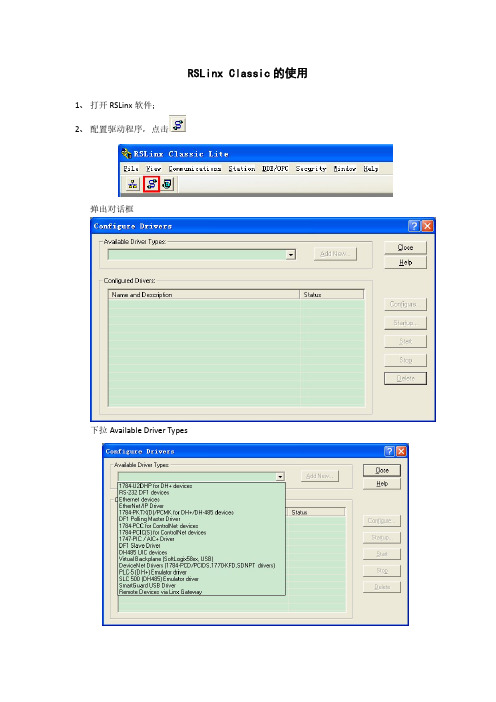
RSLinx Classic的使用1、打开RSLinx软件;2、配置驱动程序,点击弹出对话框下拉Available Driver Types2.1 其中RS-232 DF1 devices为232串口驱动,选择然后点击Add New..然后选择OK,在这里选择COM口和Device,如图选择,然后点击Auto Configruration按钮,可以看到会自动匹配串口参数。
出现AUTO CONFIGURATION SUCCESSFULL!以后表示串口通讯成功。
出现红色矩形框驱动,点击Clese然后点击,然后出现PLC就表示串口通讯成功!2.2 其中Ethernet devices为以太网驱动,选择然后点击Add New..点击OK输入IP地址,点击确定出现红色矩形框驱动,点击Clese然后点击,然后出现PLC就表示串口通讯成功!当使用直连和交叉网线时:•MicroLogix 1400以太网端口到10/100Base-T以太网交换机电缆使用直连插线引脚(1-1,2-2,3-3,6-6)。
•直接点对点10/100 Base-T电缆将MicroLogix 1400以太网端口直接连接到另一个以太网端口(或计算机的10/100Base-T端口)需要一个交叉插线引脚(1-3, 2-6, 3-1, 6-2)。
PLC液晶显示定义当输入和输出接通时,就显示为实心的矩形。
当输入和输出未接通,就显示为空心的矩形。
1400PLC组态IP地址1、在主菜单画面中LCD的使用键盘上的Up(向上)和Down(向下)键选择Advanced Set(高级设置),如下图所示。
(如果想要退出网络组态菜单,随时都可以按LCD键盘上的ESC键退出菜单。
)如果在主菜单画面中没有显示如下所示的菜单选项,按Down(向下)键,向下滚动。
2、按LCD键盘上的OK键。
显示高级设置菜单画面,如下图所示。
如果已经选择了ENET Cfg 选项,按OK键。
否则使用Up(向上)和Down(向下)键选择ENET Cfg,然后再按OK键。
MicroLogix1400以太网驱动设备产品规格使用说明
MicroLogix1400以太⽹驱动设备产品规格使⽤说明MicroLogix1400以太⽹驱动产品规格说明书[修订记录][项⽬经理填写]⼀、产品功能简介a)⽀持协议说明AB ⾃⼰的CIP扩展协议(⾮标准),协议中封装PCCC指令集。
b)⽀持的硬件型号说明:AB MicroLogix1400PLC。
c) ⽀持的连接说明及发送⽅式⽀持TCP连接,⽀持以socket发送。
⼆、驱动接⼝:3.0开发包三、设备添加⽅式a)在组态王中定义设备时请选择:PLC \ RockWell \MicroLogixEthernet \ TCPb)设备向导页选项的特殊说明:⽹络设备需要选择串⼝的原因是:⼀个设备接⼝(如Com1、⽹卡)开启⼀个线程。
c)对于串⼝设备通讯参数的推荐设置如下⽆,视具体设备⽽定四、本设备的地址格式及地址范围设备地址: IP地址:端⼝号例如:172.16.7.95:44818说明:端⼝号为可选项,如果不指定,默认为44818。
五、寄存器列说明说明:1)对于只写寄存器,请将采集频率设置为0。
2)对于A寄存器,选择字节类型时,⾼低字节的对应关系如下所⽰:RSLogix500中A9:0 = ab,那么组态王定义中的A9:0-0 = a,A9:0-1 = b。
3)T寄存器4)C寄存器5)R寄存器六、打包规格描述:1)相同⽂件号,数据长度不超过最⼤打包长度时,可以打⼀个包。
2)ST寄存器不打包。
3)打包长度最⼤240字节。
七、接收缓冲区的⼤⼩:(程序员需要提供此参数,此说明只⽤于测试⼯程师测试,⽤户⽂档中不列此项。
)1024个字节⼋、配置⽂件格式以及打包规则说明九、重点测试部分说明(需要测试⼯程师重点测试部分的说明)⼗、程序员测试特殊说明(程序员在调试程序中发现的⼀些特殊需要说明的问题,例如某个寄存器写范围超过多⼤的数据就有问题了)⼗⼀、是否需要双机热备测试?⼗⼆、驱动运⾏需要涉及的其他软件的⽀持(备注:驱动运⾏需要安装的软件或需要调⽤的库⽂件或数据库⽂件的说明)⼗三、其他软硬件环境⽀持的简要操作说明和注意事项(备注:1,和通讯相关的硬件参数的设置,例如仪表需要设备某个参数才能和组态王通讯2,设备软件上影响通讯的参数的设置⽅法,例如对于plc设备,需要⽤软件对设备进⾏特殊的参数设置后,设备才能和组态王通讯,结合图⽚说明)⼗四、具体接线图的说明(有特殊连线要求的填写)⼗五、对于性能事项的特别说明⼗六、参考资料的说明附录:3.0接⼝程序编程规范关于程序的规范,会影响到测试环节的部分a)寄存器和通道号之间的0不做限制,0通道的0可输⼊可不输⼊。
ONE学习笔记(2)

ONE学习笔记(2)昨天的图里有ONE的调试流程,依次是:1.安装软件最主要的是两个:TIA博途和Create MyVirtual Machine。
CMVM是强烈建议安装的,如果你还吃不准它能否像西门子人介绍的那么有用,你可以申请试用版本,可以试用三个月。
我过两天也准备申请个试用的,不然没软件学不下去啊。
当然还有Toolbox,AMM,等一些工具,前面的小文介绍过。
在这一步,还有非常关键的一点:设置网络,让博途能访问到CMVM。
2.调试PLC主要是做硬件配置。
当然,也可以将TST(TIA Slection Tool)选型的文件导入博途,这样可以简化硬件组态。
PLC程序可以从840Dsl上移植过来(如果同机型用过840Dsl的话),也可以重新编写,但如果有足够的调试时间,我建议重新编写,去熟悉下博途的编程。
3.将PLC项目下载到CMVM到这里,估计还有人不清楚啥叫CMVM,CMVM是个计算机软件,运行起来后,就相当于在计算机环境下的SINUMERIK ONE,它的人机界面和插补算法等等和真实的SINUMERIK ONE系统完全一致。
我们把它叫做SINUMERIK ONE的数字孪生。
借助这个数字孪生,我们就可以在计算机上做很多事情,自我学习或者做初步的虚拟调试,当然如果把CMVM和强大的MCD、NX软件结合起来,能做更多的事情。
目的就一个,在虚拟环境下,去尝试原来只有真实机床装配起来后才能做的事情,从而降低样机的风险,缩短研发时间,节省费用。
4.NC参数设置5.PLC安全集成的设置和编写安全程序(如果用到安全集成功能的话)6.NC安全集成的设置(如果用到安全集成功能的话)7.虚拟机床搭建和调试好后,待真实机床装配完成,将在CMVM 上调试好的NC数据、PLC程序、安全集成功能和用户定义画面等数据回装到真实的SINUMERIK ONE系统中。
8.调试驱动9.其它机床相关设定、补偿、测试安装软件是个费神的过程,软件有两种安装方式:方式1:将博途和CMVM安装在一台电脑上(推荐)(按步骤1-4顺序安装)方式2:使用两台电脑,分别安装博途和CMVM,即一台电脑安装博途(按步骤1-2顺序安装),另一台电脑安装CMVM(按步骤3和4顺序安装)步骤PLC项目工程软件(博途)SINUMERIK项目工程软件(CMVM)1 SIMATIC STEP7 Professional V17(TIA博途)包括SIMATIC 安全(授权)2 硬件配置和PLC编程需要的选装包SINUMERIK STEP 7 Toolbox V17,包括:· SINUMERIK 840D sl STEP 7Toolbox V17· SINUMERIK ONE STEP 7 ToolboxV173 Create MyVirtual MachineV1.2或更高版本4 SINUMERIK Virtual CNC SWV6.15或更高版本安装步骤1和步骤2,相信调试过840Dsl的工程师都熟悉(安装过无数遍)安装步骤3和步骤4,有相应的参考手册步骤3的参考手册是:SINUMERIK Create MyVirtual Machine installation instructions步骤4的参考手册是:SINUMERIK Virtual CNC SW installation instructions上述手册,到这面网页去找:/CNC4YOU/Home/Article/2776等找到软件后,再详细描述安装过程。
西门子RUGGEDCOM RX1400多协议智能节点说明书

Multiprotocol intelligent nodeRUGGEDCOM RX1400BrochureEdition01/2015Siemens RUGGEDCOM RX1400 is a multiprotocol intelligent node which combines Ethernet switching, routing, and firewall functionality with various wide area connectivity options. The device has IP40 degree of protection, does not use internal fans for cooling and supports -40° C to +85° C extended temperature range.The RUGGEDCOM RX1400 provides a high level of immunity to electromagnetic interference, heavy electrical surges, extreme temperature and humidity for reliable operation in mission critical applications. It can be found in electric utility substations, traffic control cabinets, railways, oil and gas and other harsh environments.BenefitsCost effective solution for large scale deploymentsThe RUGGEDCOM RX1400 is a compact Layer 3 integrated switch and router – ideal for large scale, hierarchical networks, capable of transporting data from both modern Ethernet-based IEDs and from legacy or low cost serial IEDs. High availabilityThe RUGGEDCOM RX1400 uses fiber and cellular connections simultaneously. The dual SIM card slots enable cellular provider redundancy, allowing selection of the best performing network.Space saving installationThe RUGGEDCOM RX1400‘s small form factor allows it tofit into existing enclosures used in substation automation, distribution automation, roadside and oil & gas applications. Reduced maintenance costsThe RUGGEDCOM RX1400‘s rugged design will deliver the same high field demonstrated MTBFs as the rest of the RUGGEDCOM product portfolio, reducing truck rolls and maintenance costs.OverviewWireless2 x RS232 / 422 / 485Failsafe relay form Cm mLTE / HSPA / GPRSSerial 2 x RS 232/ 422/ 485Ethernet4 x 10/100 TXPluggable optics2 x SFP ports GigabitMemoryMicro SD slot for application data storageManagementLocal serial consoleCarrierDual SIM supportRelayFailsafe rel ay for m C Power supply 12 or 24 VDCGPSGPS input for location data88 mm150SoftwareThe RUGGEDCOM RX1400 runs the ROX II operating system and delivers carrier grade routing and switching performance to the network edge and beyond!The ROX firmware supports the most used network technologies, such as different routing protocols, multiple network fault recovery solutions, including Siemens eRSTP (enhanced Rapid Spanning Tree Protocol), and others. Software features◾Enhanced security / reliability through data and control path separation◾Single file configuration automation ensures easy installation and configuration control◾Automatic rollback in the event of configuration errors ◾NETCONF configuration interface supports powerful remote configuration and status features◾Port rate and Broadcast Storm Limiting◾Port configuration, status, statistics, mirroring◾Routing Protocols OSPF, BGP, RIPv1 and v2◾Virtual Router Redundancy Protocol (VRRP)◾NTP time synchronization (client and server)◾Redundancy protocols MSTP 802.1Q-2005, RSTP (802.1w) and Enhanced Rapid Spanning Tree (eRSTP) for network fault recovery◾Quality of service (802.1p) for real-time traffic Cyber securityCyber security is an important issue in many industries where advanced automation and communications networks play a crucial role in mission critical applications and where high reliability is of paramount importance. Key RUGGEDCOM RX1400 features that address security issues at the local area network level include:◾IPSEC – The integrated hardware encryption engine delivers high performance IPSEC traffic without using the main processor◾Passwords – compliant with NERC guidelines including provision for RADIUS based authentication◾SSH / SSL – extends capability of password protection to add encryption of passwords and data as they cross the network◾Enable / disable ports – capability to disable ports so unauthorized devices can’t connect to unused ports◾802.1Q VLAN – provides the ability to logically segregate traffic between predefined ports on switches◾SNMPv3 – encrypted authentication and access security ◾HTTPS – for secure access to the web interface◾802.1x – to ensure only permitted devices can connect to the device◾MAC access list – control access to devices that do not support RADIUSFeaturesRugged RatedThe RUGGEDCOM RX1400 is a Rugged Rated product, which means that it has been specifically designedand tested to withstand the demands of harsh environments. As with all Rugged Rated products, Highly Accelerated Life Testing (HALT) has been used in the early stages of product development – to detect any design and performance issues.Reliable operation in harsh electrical environments◾IEC 61850-3 and IEEE 1613 (electric power substations)◾IEC 61000-6-2 and IEC 61800-3 (industrialenvironments)◾NEMA TS-2 (traffic control equipment)◾EN 50121-4 (railway applications)Error-free operation in high EMI environments◾Z ero-Packet-Loss technology for fiber-based networking devices◾IEEE 1613 class 2 error-free performance under EMI stress ◾Fiber optic ports supporting both short and long haul fiber Operation over a wide temperature range ◾-40° C to +85° C◾Passive cooling – no fans◾CSA/UL 60950 safety approved to +85° C High availability◾Integrated power supply◾L ow voltage DC: 24 VDC (10-36 VDC) Industrial installations◾Full metal enclosure◾Heavy duty mounting◾I ndustrial terminal blocks for powerand I/O connectionsThe RUGGEDCOM RX1400 provides redundant connection of end devices by fiber optic and / or cellular networks for more reliability in case of network failure.Wayside infrastructureUse casesThe RUGGEDCOM RX1400 can be used to connect low voltage substations and distributed generation plants reliably via public celullar networks.Distribution generationOil and gasThe RUGGEDCOM RX1400 makes it possible to remotely monitor field data using multiple kinds of communications through cellular networks, or fiber optics, or both in a redundant way.Order optionsSiemens AGProcess Industries and Drives Process Automation Postfach 48 4890026 NÜRNBERG GERMANYSiemens Canada Limited 300 Applewood Crescent Concord, Ontario, L4K 5C7 CANADA Subject to change without prior notice Article No. 6ZB5531-0AL02-0BA0 DR.PN.RG.15.XXBR.95.26 / Dispo 26000 BR 0115 2. WÜ 8 EnPrinted in Germany© Siemens AG 2015The information provided in this brochure contains descriptions or characteristics of performance which in case of actual use do not always apply as described or which may change as a result of further development of the products. An obligation to provide the respective characteristics shall only exist if expressly agreed in the terms of contract. Availability and technical specifications are subject to change without notice.All product designations may be trademarks or product namesof Siemens AG or supplier companies whose use by third parties for their own purposes could violate the rights of the owners.。
克罗韦尔 PowerMonitor 1000 单元产品目录号升级 说明书
安装指南PowerMonitor 1000 单元产品目录号升级产品目录号 1408-UPT1-E3、1408-UPT2-E3、1408-UPE1-E3、1408-UPE2-E3、1408-UP485-ENT、1408-UPT3-E3主题页码重要用户须知2使用 ControlFLASH 软件工具升级设备产品目录号3其它资源9本手册提供了 PowerMonitor™ 1000 单元产品目录号的升级说明。
重要事项在开始进行操作之前,请先确认已进行了正确的网络连接,并确认已在 RSLinx® Classic 软件中组态了网络驱动程序。
2罗克韦尔自动化出版物 1408-IN002B-ZH-P - 2015 年 7 月PowerMonitor 1000 单元产品目录号升级重要用户须知在安装、配置、操作或维护设备之前,请仔细阅读本文档及“其它资源”部分列出的文档,了解设备的安装、配置和操作信息。
用户需要了解安装和接线指南以及所有适用规范、法律和标准的相关要求。
安装、调节、投入使用、操作、装配、拆卸和维护等活动均要求由经过适当培训的人员遵照适用法规执行。
如未按照制造商指定的方法使用设备,则设备提供的保护功能可能会受到影响。
对于由于使用或应用此设备而导致的任何间接损害或由此引起的损害,罗克韦尔自动化公司在任何情况下均不承担任何责任。
本手册中的实例和图表仅供说明之用。
由于具体安装情况存在许多可变因素及要求,因此罗克韦尔自动化公司概不承担根据实例及示意图进行实际使用而产生的任何责任或义务。
对于因使用本手册中所述信息、电路、设备或软件而引起的专利问题,罗克韦尔自动化公司不承担任何责任。
未经罗克韦尔自动化公司书面许可,任何单位或个人不得复制本手册之全部或部分内容。
在整本手册中,我们在必要的地方使用了以下注释,来提醒您注意相关的安全事宜。
标签也可贴放在设备表面或内部,用于提供特定警示。
警告:标识在危险环境下可能导致爆炸进而造成人员伤亡、财产损坏或经济损失的做法或情况的信息。
- 1、下载文档前请自行甄别文档内容的完整性,平台不提供额外的编辑、内容补充、找答案等附加服务。
- 2、"仅部分预览"的文档,不可在线预览部分如存在完整性等问题,可反馈申请退款(可完整预览的文档不适用该条件!)。
- 3、如文档侵犯您的权益,请联系客服反馈,我们会尽快为您处理(人工客服工作时间:9:00-18:30)。
ERX700/ERX1400软件升级学习笔记1.ERX模块工作状态描述ERX的模块主要有SRP和line module及i/o module组成,工作状态描述的是SRP和line module的运行情况。
正常情况下除了备用的SRP状态是standby 以外,所有模块的工作状态应为online。
通过show version可以得到各个模块的工作状态:ERX-1400-CN#show versionJuniper Edge Routing Switch ERX-1400Copyright (c) 1999-2003 Juniper Networks, Inc. All rights reserved.System Release: erx_5-0-3.relVersion: 5.0.3 release-0.0 [BuildId 1625] (December 30, 2003 17:41) System running for: 6 days, 16 hours, 16 minutes, 18 seconds(since WED JUL 07 2004 18:40:26 UTC)runningslot state type admin spare release slot uptime---- -------------- ---------------- ------- ----- ------------- -------------0 --- --- --- --- --- ---1 inactive GE enabled --- erx_5-0-3.rel 6d16h:11m:16s2 --- --- --- --- --- ---3 online FE-8 enabled --- erx_5-0-3.rel 6d16h:11m:17s4 hardware error OC3/OC12/DS3-ATM enabled --- erx_5-0-3.rel ---5 --- --- --- --- --- ---6 online SRP-10Ge enabled --- erx_5-0-3.rel 6d16h:14m:48s7 standby SRP-10Ge enabled --- erx_5-0-3.rel ---8 not present OC3-4A enabled --- erx_5-0-3.rel ---9 --- --- --- --- --- ---10 --- --- --- --- --- ---11 not responding OC3/OC12/DS3-ATM enabled --- erx_5-0-3.rel ---12 --- --- --- --- --- ---13 online GE enabled --- erx_5-0-3.rel 6d16h:11m:17s以下是对各个工作状态的描述:Ø Inactive,通常是由于该槽位的i/o module 未连接引起的。
Ø Hardware error ,这表明该line module 没有通过上电自检,一般是该模块有硬件问题,通过硬件诊断可以得到log申请case(步骤见下节)。
Ø Not present ,如果原先正常工作的line module 被拔离该槽位会出现该状态。
通过配置模式下的slot erase x可以将该信息清除。
(操作前需确认板卡是否在槽位上)Ø Not responding,通常是SRP无法与该line card 建立控制连接通道,可能是line card 有故障,可以通过操作模式下的reload slot x对该模块重启,如果故障依旧,需要通过硬件诊断确认。
需要注意的是slot erase x 会同时清空相关槽位的所有配置,应用之前需要确认。
而reload slot x 只是将某个line card 进行重启操作,不会影响配置文件。
2.如何对LINE MODULE 实施硬件诊断板卡在工作时出现异常,如果无法通过重启/更换槽位等方法恢复工作时,只有通过更换新的模块。
通过硬件诊断可以得到模块的故障信息。
在所有line card和SRP上都有一个RJ45的接口,诊断时需要将console线连接到该接口上。
ERX 的console线由一根直通网线以及两个DB-9 到RJ45的转换接头(cross over和strait through 各一个)组成。
进行硬件诊断用的console 线需要一根直通网线及一个crossover 的DB-9 到RJ45的转换接头。
首先将terminal调整到19.2kbps,打开termial的日志功能,将需要诊断的模块重机框中拔出,连接console线后将模块插回机框。
此时该linecard 进行上电自检,当出现倒计数时键入空格键,terminal会提示:2/1/0? 选择0,该line card 将刷新板卡上的flash(内含系统软件)。
正常情况下,linecard 会启动到boot##提示,同时linecard上的online等点亮,表明该linecard通过诊断已经恢复工作。
该过程需要耗时3分钟左右。
如果linecard通过上述诊断最终出现fail灯常亮,表明该模块有硬件故障,取得日志文件后申请返修。
除了对板卡进行硬件诊断外,我们还可以通过show reboot-history可以迅速了解模块故障或重启的原因:ERX-1400-CN#sh reboot*** Entry 1 ***time of reset: THU JUL 08 2004 16:47:18 UTCrun state: unknownimage type: bootlocation: slot (4)build date: 0x3ff1aed1 TUE DEC 30 2003 16:58:57 UTCreset type: user reboot, task "scheduler", reason "not specified"*** Entry 2 ***time of reset: THU JUL 08 2004 16:45:36 UTCrun state: unknownimage type: bootlocation: slot (4)build date: 0x3ff1aed1 TUE DEC 30 2003 16:58:57 UTCreset type: power cycle观察某个linemodule 的reset type,如果出现反复重启并且是“power cyclye” 那么可能是该linecard 与机框接触不良,或者是由于该linecard上的DC-DC模块出现故障。
前者可以通过更换槽位,如果更换之后同样出现类似的log表明该模块的电源模块有问题,直接提起返修即可。
3.软件升级问题及系统配置的恢复ERX的系统软件是存放在内部flash上的一个单一的.rel文件。
该文件通过ftp 方式从ftp server上拷贝后生成。
在ftp server上的升级文件由一个xxx.rel文件(例如erx-5-0-3.rel)和多个.exe文件组成,该.rel文件是一个索引文件,内部描述了所有模块软件(subsystem)的名称和大小,通常情况下我们不能对该文件修改。
默认情况下我们得到的升级文件包含支持各个类型linecard的模块文件,同时在ftp 拷贝生成ERX flash上的.rel系统软件也包含了所有subsystem,该.rel就是一个full 版本的系统软件。
通常在进行ftp拷贝时会得到如下提示:“copy source not valid”,一种可能是由于ftp server 的帐号设置和erx上的host 配置不匹配引起的,另外如果需要拷贝的subsystem文件在ftp server上不存在也可能引起该现象。
如果ERX上有两个SRP,在reload 之前必须进行同步操作:ERX-1400-CN#synchronizePlease wait…………………….ERX-1400-CN#虽然此时ERX提示同步完成,我们必须通过show utilization进行确认。
当standby的SRP的利用率为0%时才表明同步操作真正完成,可以进行重启了为了确保新软件的正常运行,一般建议通过reload slot x 将standby的SRP先进行重启(不影响业务,耗时3分钟左右),此后如果show version 显示新的软件已经被备用SRP运行,说明软机没有问题,此时可以重启主用的SRP。
升级失败的对策:主要现象是SRP一直在启动状态,且业务中断。
如果有两块SRP可以尝试将有问题的SRP拔出机框,即强行切换到备用SRP的方式进行恢复。
如果只有一块SRP那么只能通过如下方式和顺序进行恢复:Ø 重启SRP(关电/插拔均可)Ø console出现倒计数时键入mb,强行进入boot 模式Ø 用出厂配置尝试重启:boot##boot configure factory-defaults然后boot##reload。
Ø 如果系统启动成功并且是新的软件版本说明配置文件有问题,此时可以通过配置恢复方式(见以下相关配置)进行配置恢复。
Ø 如果出厂配置时系统仍启动失败表明新的系统软件有问题或者flash有故障。
Ø 尝试恢复到以前的软件版本:boot## boot system old.rel然后重启。
Ø 如果启动失败则我们不得不需要对flash进行初始化操作:boot##flash-disk initilize格式化flashboot##ip address x.x.x.x x.x.x.x配置以太口(SRP I/O 上)ipboot##host test x.x.x.x ftp配置host需要重启设备boot##copy test:/erx-x.rel erx-x.rel重传系统软件Ø 然后重启后恢复配置。
系统配置的恢复:方法一、将f拷贝到flash上,在配置模式下boot configure f once然后重启。
方法二、将backup.scr拷贝到flash上,在操作模式下,通过configure file backup.scr恢复系统配置。
方法一速度较快但需要重启系统,方法二不需重启系统但是需要确保所有模块已经处于online状态才可以进行恢复。
软件升级的步骤:Ø 备份配置:host ftpserver x.x.x.x ftp xxx xxx 配置hostcopy running-configure fshow config >backup.scrcopy f ftpserver:/fcopy backup.scr ftpserver:/backup.scrØ 从ftp server拷贝系统软件到erx的flash上copy ftpserver:/erx-5-0-3.rel erx-5-0-3.relØ 在配置模式下指定新软件boot system erx-5-0-3.relØ 在操作模式下进行配置同步synchronizeØ 重启备用SRPreload slot x x 是备用SRP的所在的槽位Ø 重启主用SRP(此时业务中断,时间在5~15分钟)reload slot x x是主用SRP的所在的槽位设备升级正常但是拨号业务无法恢复:现象是大部分拨号用户无法进行拨号连接(提示用户名口令错),这可能是由于在重启erx时大量的拨号用户在线但是erx没有及时发出拆线记录(例如突然断电重启erx),这样在radius上这些用户都还处于连接状态,同时radius对用户帐号进行了限制,同一帐号只允许一个session。
