EC3C-T-20-30.000M-I2中文资料
NEC Tokin Product Guide
10K 1K 100 10
Impedance (⏲)
02-200
10K 1K 100 10
02-100
02-300
02-500
02-101
3 6 1 3 6 1 3 6 1 3 6 1 3
1 1K
10K
100K
1M
10M
30M
1 1K
3
6
1
3
6
1
3
6
1
3
6
1
3
10K
100K
1M
10M
30M
Frequency (Hz)
●本PDF商品目录的内容发生变更或停止生产時,恕不另行通知,请在订购时确认最新信息。 ●在订购本PDF商品目录中的产品时,请申请交货规格书,以便进一步确认更详细的规格参数。 ●在使用本PDF商品目录中的产品时,请确认印刷版商品目录中的“安全相关注意事项”的内容以及其他与安全有关的注意事项。
0001EMCVOL01C1503E1
0001EMCVOL01C1503E1
公模
SC Coils 标准型
[RoHS [RoHS 对应品 对应品] ]
型号
最大定额电流 (A)
SC-02-101 SC-02-100 SC-02-200 SC-02-300 SC-02-500 SC-02-800 SC-05-100 SC-05-200 SC-05-500 SC-05-800 SC-10-100 SC-10-200 SC-15-100 SC-15-200 SC-20-100 SC-30-100
2 2 2 2 5 5 5 4 4 10 10 10 12 15 15 18
电感值 (mH) 最小 1 2 3 5 1 2 3 5 8 1 2 3 1.5 0.5 1 0.5
MAX213CAI-T中文资料

General DescriptionThe MAX200–MAX211/MAX213 transceivers are designed for RS-232 and V.28 communication inter-faces where ±12V supplies are not available. On-board charge pumps convert the +5V input to the ±10V need-ed for RS-232 output levels. The MAX201 and MAX209operate from +5V and +12V, and contain a +12V to -12V charge-pump voltage converter.The MAX200–MAX211/MAX213 drivers and receivers meet all EIA/TIA-232E and CCITT V.28 specifications at a data rate of 20kbps. The drivers maintain the ±5V EIA/TIA-232E output signal levels at data rates in excess of 120kbps when loaded in accordance with the EIA/TIA-232E specification.The 5µW shutdown mode of the MAX200, MAX205,MAX206, and MAX211 conserves energy in battery-powered systems. The MAX213 has an active-low shut-down and an active-high receiver enable control. Two receivers of the MAX213 are active, allowing ring indica-tor (RI) to be monitored easily using only 75µW power.The MAX211 and MAX213 are available in a 28-pin wide small-outline (SO) package and a 28-pin shrink small-outline (SSOP) package, which occupies only 40% of the area of the SO. The MAX207 is now avail-able in a 24-pin SO package and a 24-pin SSOP. The MAX203 and MAX205 use no external components,and are recommended for applications with limited circuit board space.ApplicationsComputersLaptops, Palmtops, Notebooks Battery-Powered Equipment Hand-Held Equipment Next-Generation Device Features ♦For Low-Cost Applications:MAX221E: ±15kV ESD-Protected, +5V, 1µA, Single RS-232 Transceiver with AutoShutdown™♦For Low-Voltage and Space-Constrained Applications:MAX3222E/MAX3232E/MAX3237E/MAX3241E/MAX3246E: ±15kV ESD-Protected, Down to 10nA,+3.0V to +5.5V, Up to 1Mbps, True RS-232Transceivers (MAX3246E Available in UCSP™Package)♦For Space-Constrained Applications:MAX3228E/MAX3229E: ±15kV ESD-Protected,+2.5V to +5.5V, RS-232 Transceivers in UCSP ♦For Low-Voltage or Data Cable Applications:MAX3380E/MAX3381E: +2.35V TO +5.5V, 1µA,2Tx/2Rx RS-232 Transceivers with ±15kV ESD-Protected I/O and Logic Pins ♦For Low-Power Applications:MAX3224E–MAX3227E/MAX3244E/MAX3245E:±15kV ESD-Protected, 1µA, 1Mbps, +3.0V to+5.5V, RS-232 Transceivers with AutoShutdown Plus™MAX200–MAX211/MAX213+5V , RS-232 Transceivers with 0.1µF External Capacitors ________________________________________________________________Maxim Integrated Products 119-0065; Rev 6; 10/03For pricing, delivery, and ordering information,please contact Maxim/Dallas Direct!at 1-888-629-4642, or visit Maxim’s website at .Ordering Information appears at end of data sheetAutoShutdown, AutoShutdown Plus, and UCSP are trademarks of Maxim Integrated Products, Inc.MAX200–MAX211/MAX213+5V , RS-232 Transceiverswith 0.1µF External Capacitors______________________________________________________________________________________19Ordering Information*Contact factory for dice specifications.M A X 200–M A X 211/M A X 213+5V , RS-232 Transceiverswith 0.1µF External Capacitors Maxim cannot assume responsibility for use of any circuitry other than circuitry entirely embodied in a Maxim product. No circuit patent licenses are implied. Maxim reserves the right to change the circuitry and specifications without notice at any time.20____________________Maxim Integrated Products, 120 San Gabriel Drive, Sunnyvale, CA 94086 408-737-7600©2003 Maxim Integrated ProductsPrinted USAis a registered trademark of Maxim Integrated Products.Package Information(The package drawing(s) in this data sheet may not reflect the most current specifications. For the latest package outline information,go to /packages .)。
产品推介ppt_产品推介

产品推介ppt_产品推介源科全球首款单芯片SATA DOM固态硬盘小源面市国内固态存储领域的领导者源科公司宣布推出全球首款单芯片SATA DOM固态硬盘“小源”,它是rSSD系列新增的一员“小”将。
小源SATA DOM固态硬盘是基于源科自主研发的芯片级rSSD,该产品采用了SATA II接口,相比曾经市场主流的IDE/ ATA DOM盘,其性能和可靠性更加稳定。
采用rSSD作为存储介质的“小源”同样具有小尺寸、高性能的优点,同时,该产品具备的写保护功能使其可靠性更强。
值得一提的是,源科小源SATA DOM 硬盘标准版配备5V外接电源,也可为进一步节省空间选配7引脚VCC电源。
风河推出Android车载信息娱乐系统快速开发软件工具风河公司近日推出汽车市场专用软件,进一步扩大其Android产品组合,Wind River Solution Accelerator for Android - Automotive主要功能包括:连接iPod/iPhone/iPad以提供丰富的多媒体功能、消费者可修改的定制用户接口以及FM收音机功能,此外,风河还提供软件和系统集成方面的专业服务,为不同的客户项目提供支持。
此开发工具能够帮助车载信息娱乐设备制造商缩短基于Android平台系统的开发时间。
华北工控“CedarTrail”智能应用平台满足不同需求自英特尔新一代凌动“CedarTrail”平台上市后,华北工控就发布了2款Mini ITX主板,公司根据市场反馈又研发了多款针对不同应用领域的新的“CedarTrail”智能应用平台,包括满足安防数字视频监控、SOHO型的存储服务以及工业现场自动化控制需求的BPC-7932、应用于数字标牌、汽车车载娱乐、多媒体设备、零售等智能终端的BIS-6555和适合轨道交通、智能医疗设备以工业自动化领域应用的EMB-3930等。
ST量产STM32 F0入门级MCU意法半导体(ST)开始量产STM32 F0系列32位微控制器。
MEC-4032-中英文说明书-C04-2413-025631

特种计算机Industrial Computer产品说明书User ManualMEC-4032微型低功耗无风扇嵌入式整机Low Power Fanless Micro Embedded PCVersion: C04法律资讯警告提示为了您的人身安全以及避免财产损失,必须注意本手册中的提示。
人身安全的提示用一个警告三角表示,仅与财产损失有关的提示不带警告三角。
警告提示根据危险等级由高到低如下表示。
危险表示如果不采取相应的小心措施,将会导致死亡或者严重的人身伤害。
警告表示如果不采取相应的小心措施,可能导致死亡或者严重的人身伤害。
小心带有警告三角,表示如果不采取相应的小心措施,可能导致轻微的人身伤害。
注意表示如果不注意相应的提示,可能会出现不希望的结果或状态。
合格的专业人员本文件所属的产品/系统只允许由符合各项工作要求的合格人员进行操作。
其操作必须遵照各自附带的文件说明,特别是其中的安全及警告提示。
由于具备相关培训及经验,合格人员可以察觉本产品/系统的风险,并避免可能的危险。
EVOC产品请注意下列说明:警告EVOC产品只允许用于目录和相关技术文件中规定的使用情况。
如果要使用其他公司的产品和组件,必须得到EVOC推荐和允许。
正确的运输、储存、组装、装配、安装、调试、操作和维护是产品安全、正常运行的前提。
必须保证允许的环境条件。
必须注意相关文件中的提示。
免责声明本公司保留对此手册更改的权利,产品后续相关变更时,恕不另行通知。
对于任何因安装、使用不当而导致的直接、间接、有意或无意的损坏及隐患概不负责。
订购产品前,请向经销商详细了解产品性能是否符合您的需求。
EVOC是研祥智能科技股份有限公司的注册商标。
本手册所涉及到的其他商标,其所有权为相应的产品厂家所拥有。
研祥智能科技股份有限公司©2012,版权所有,违者必究。
未经许可,不得以机械、电子或其它任何方式进行复制。
保修条款:产品保修期一年。
用户如另有要求,以双方签署的合同为准。
X20(c)PS3300供电模块说明书
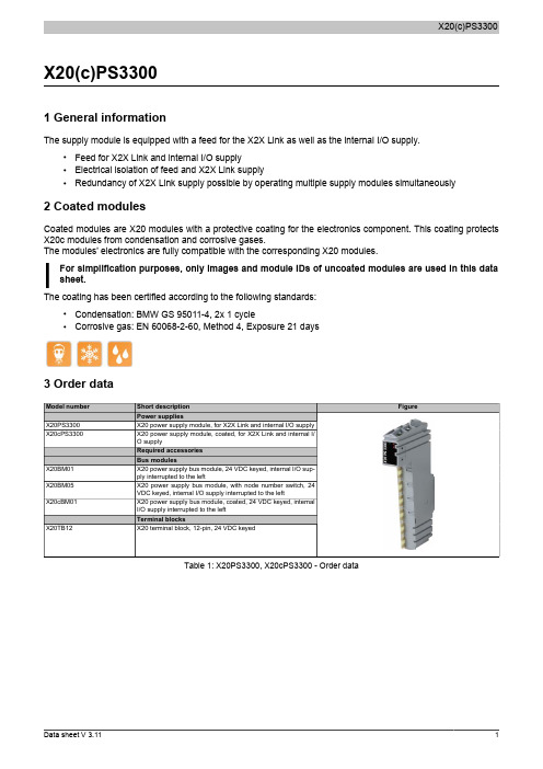
X20(c)PS33001 General informationThe supply module is equipped with a feed for the X2X Link as well as the internal I/O supply.•Feed for X2X Link and internal I/O supply•Electrical isolation of feed and X2X Link supply•Redundancy of X2X Link supply possible by operating multiple supply modules simultaneously2 Coated modulesCoated modules are X20 modules with a protective coating for the electronics component. This coating protects X20c modules from condensation and corrosive gases.The modules' electronics are fully compatible with the corresponding X20 modules.For simplification purposes, only images and module IDs of uncoated modules are used in this data sheet.The coating has been certified according to the following standards:•Condensation: BMW GS 95011-4, 2x 1 cycle•Corrosive gas: EN 60068-2-60, Method 4, Exposure 21 days3 Order dataTable 1: X20PS3300, X20cPS3300 - Order data4 Technical dataTable 2: X20PS3300, X20cPS3300 - Technical dataTable 2: X20PS3300, X20cPS3300 - Technical data1)The values specified here are maximum values. The exact calculation is also available for download as a data sheet with the other module documentation on the B&R website.2)Ta min.: 0°CTa max.: See environmental conditions3)In parallel operation, only 75% of the rated power can be assumed. It is important to make sure that all power supplies operating in parallel are switched on and off at the same time.5 LED status indicatorsFor a description of the various operating modes, see the section "re LEDs" in chapter 2 "System characteristics"of the X20 system user's manual.6 PinoutX 20 P S 3300Ir e7 Connection examplesWith 2 separate suppliesWith a supply and jumper8 DeratingThe rated output current for the supply is 7 W. Derating must be taken into consideration based on mounting orientation.Ambient temperature [°C]-2505740455055Installation position Horizontal VerticalN o m i n a l o u t p u t p o w e r [W ]4609 Register description9.1 General data pointsIn addition to the registers listed in the register description, the module also has other more general data points. These registers are not specific to the module but contain general information such as serial number and hardware version.These general data points are listed in the "General data points" section of chapter 4 "X20 system modules" in the X20 system user's manual.9.2 Function model 0 - Standard9.3 Function model 254 - Bus controllerThe module occupies 1 logical analog slot on CAN I/O.1)The offset specifies the position of the register within the CAN object.9.4 Module statusName:Module statusThe following voltage and current states of the module are monitored in this register:Bus supply current: A bus supply current of >2.3A is displayed as a warning.Bus supply voltage: A bus supply voltage of <4.7V is displayed as a warning.24 VDC I/O supply voltage:An I/O supply voltage of <20.4 V is displayed as a warning.Bit structure:9.5 Bus supply currentName:SupplyCurrentThis register displays the bus supply current measured at a resolution of 0.1 A.9.6 Bus supply voltageName:SupplyVoltageThis register displays the bus supply voltage measured at a resolution of 0.1 V.9.7 Minimum cycle timeThe minimum cycle time defines how far the bus cycle can be reduced without communication errors occurring. It should be noted that very fast cycles decrease the idle time available for handling monitoring, diagnostics and acyclic commands.9.8 Minimum I/O update timeThe minimum I/O update time defines how far the bus cycle can be reduced while still allowing an I/O update to take place in each cycle.。
FLAC3D资料
第四章FLAC3D数值模拟4.1 FLAC3D数值分析软件介绍4.2 模型建立与运行4.2.1 建立模型4.2.2 各工况的数值模拟(1)(2)(3)4.3 水平荷载下刚性单桩工作性状分析4.4 水平荷载下带帽刚性桩工作性状分析4.5 水平荷载下带帽刚性桩复合地基工作性状分析4.5.1 桩长、桩径及长径比、桩帽大小、褥垫层厚度带帽刚性桩复合地基应力场和位移场的影响4.5.2 各计算参数的敏感性分析注:本章与第三章要相对应,分三类(刚性单桩、带帽刚性桩、带帽刚性桩复合地基),每一类又有多少工况,依据是什么?第四章FLAC3D数值模拟4.1 FLAC3D数值分析软件介绍自R.W.Clough 1965年首次将有限元引入土石坝的稳定性分析以来,数值模拟技术在岩土工程领域获得了巨大的进步,并且成功的解决列入许多重大的工程问题。
近代个人电脑的出现以及其计算能力的飞速发展,使得分析人员在室内进行岩土工程数值模拟成为可能,也使得数值模拟技术逐渐成为岩土工程研究和设计的必不可少的方法之一。
数值模拟的优势在于有效的延伸和扩展了分析人员的认知范围,为分析人员洞悉岩土体内部的破坏机理提供了强有力的可视化工具。
因此,岩土工程数值模拟软件必须做到专业性、可视化和完善的信息输出能力,才能更方便的帮助分析人员研究问题。
FLAC3D等软件的出现是数值模拟工程发展的一个里程碑。
FLAC3D软件是由Itasca公司研发推出的一款数值分析软件,其界面简单明了,特点鲜明,使用特征和计算特征别具一格,因此在岩土工程中应用广泛,并享有盛誉。
FLAC3D是一个三维有限差分程序,它是二维有限差分程序FLAC2D的扩展,能够进行土质、岩石及其他材料的三维结构受力特性模拟和塑性流动分析。
FLAC3D可对分析的单元进行线性或非线性本构模型的定义,当材料发生屈服流动后,网格能够相应的发生变形和移动(大变形模式)。
其采用了显示拉格朗日算法和混合-离散分区技术,能够非常准确的模拟材料的塑性破坏和流动。
般特 ECscan20 30 40 笔式电导率仪 使用说明书
ECscan20/30/40笔式电导率仪使用说明上海般特仪器有限公司1 I综述感谢您选择般特仪器的ECscan 系列笔式电导率仪。
这本用户手册循序渐进地描述了测量仪的各项功能与特征。
使用前,请仔细阅读。
型号 测量参数 ECscan20 电导率 ECscan30 电导率, TDS ECscan40 电导率, TDS, 盐度 安装电池 1. 拧下测量仪前端的电极固定圈,取下电极。
2. 将2节AAA 电池插入电池仓,注意极性。
3. 对准插槽,将电极缓慢推入主机,顺时针拧入电极固定圈 直至锁紧。
按键 按键 功能 • 开关测量仪 • 锁定或解锁测量 • 退出校准、设置并且返回测量 • 开始校准 • 按住键进入设置菜单• 选择一个选项 • 确认校准、设置或显示的选项• 切换测量模式显示屏图标描述表示正在测量 CAL 表示正在校准SETUP 表示正在设置选项或数值 ATC 表示自动温度补偿已启用使用前取下电极保护帽,如果传感器已干燥,将电极浸入自来水约10分钟。
开关测量仪• 按住Meas 键约5秒开机。
• 按住Meas 键关机。
如果8分钟内无按键操作,测量仪将自动关机以节省电能。
传感器I 2设置菜单ECscan 系列笔式电导率仪内含一个简洁的设置菜单用于自定义功能选项以满足使用偏好,下表描述了各菜单项的功能。
菜单项 选项与描述 校准点 设置校准点的数量。
1点(默认) 2点 3点 TDS 系数 设置默认的电导率 − TDS 转换系数。
测量单位 设置默认的温度单位。
摄氏度(默认) 华氏度 温度校准 参考第3页。
测量值±10°C 测量值±10°F 自动锁定 设置是否自动判别并锁定测量终点。
启用禁用(默认) 自动关机设置8分钟内无按键操作是否自动关机。
启用(默认)禁用 重置测量仪 设置是否删除校准数据并且恢复测量仪至工厂默认设置。
注意,一旦启用,测量仪必须重新校准。
Ice-O-Matic CD40030和CD40022酒店冰箱服务部件手册说明书

MODEL CD40030 and CD40022
Includes 50Hz.and 3 phase Units
14-1014 Date 9/08/16
11100 E. 45th Avenue • Denver , CO 80239 •
CD40022 and CD40030 Service Parts
CD40030 & CD40022 Front Panel
1
2
3 11
4
7
8
10
9
Item Number
1 2
3 4
5
Part
Number
Description
1011351-44 Screw
1011351-106 CD40030 stiffener
16 14
15
12
1011351-20 Right side flange for coin
mech model
13
1011351-01 Door shim
14
1011351-60 Door and lock
14a 1011351-64 Lock and key
14b 1011351-65 Key
15
8
9031046-27 Screw
9
1011351-82 Foam gasket, 6” per side
10
1011351-16 Grill
11a 1011351-14 CD40022, CD40030, CD40230 dispense housing
11b 1011351-15 CD40130 dispense housing
Page 3
MEMORY存储芯片MAX202ECPE中文规格书
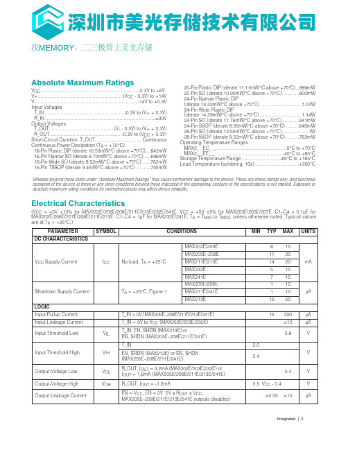
Integrated | 2Absolute Maximum RatingsV CC ..........................................................................-0.3V to +6VV+................................................................(V CC - 0.3V) to +14VV-............................................................................-14V to +0.3VInput VoltagesT_IN............................................................-0.3V to (V+ + 0.3V)R_IN...................................................................................±30VOutput VoltagesT_OUT.................................................(V- - 0.3V) to (V+ + 0.3V)R_OUT......................................................-0.3V to (V CC + 0.3V)Short-Circuit Duration, T_OUT....................................ContinuousContinuous Power Dissipation (T A = +70°C)16-Pin Plastic DIP (derate 10.53mW/°C above +70°C)....842mW16-Pin Narrow SO (derate 8.70mW/°C above +70°C).....696mW16-Pin Wide SO (derate 9.52mW/°C above +70°C)......762mW16-Pin TSSOP (derate 9.4mW/°C above +70°C)...........755mW 20-Pin Plastic DIP (derate 11.11mW/°C above +70°C)...889mW 20-Pin SO (derate 10.00mW/°C above +70°C).............800mW 24-Pin Narrow Plastic DIP (derate 13.33mW/°C above +70°C) ...............................1.07W 24-Pin Wide Plastic DIP (derate 14.29mW/°C above +70°C)................................1.14W 24-Pin SO (derate 11.76mW/°C above +70°C).............941mW 24-Pin SSOP (derate 8.00mW/°C above +70°C)..........640mW 28-Pin SO (derate 12.50mW/°C above +70°C)....................1W 28-Pin SSOP (derate 9.52mW/°C above +70°C)..........762mW Operating Temperature Ranges MAX2_ _EC_ _.....................................................0°C to +70°C MAX2_ _EE_ _...................................................-40°C to +85°C Storage Temperature Range.............................-65°C to +165°C Lead Temperature (soldering, 10s).................................+300°C Electrical Characteristics(V CC = +5V ±10% for MAX202E/206E/208E/211E/213E/232E/241E; V CC = +5V ±5% for MAX203E/205E/207E; C1–C4 = 0.1µF for MAX202E/206E/207E/208E/211E/213E; C1–C4 = 1µF for MAX232E/241E; T A = T MIN to T MAX ; unless otherwise noted. Typical values are at T A = +25°C.)Stresses beyond those listed under “Absolute Maximum Ratings” may cause permanent damage to the device. These are stress ratings only, and functional operation of the device at these or any other conditions beyond those indicated in the operational sections of the specifications is not implied. Exposure to absolute maximum rating conditions for extended periods may affect device reliability.找MEMORY 、二三极管上美光存储Integrated | 12MAX202E–MAX213E,MAX232E/MAX241E±15kV ESD-Protected, 5V RS-232 Transceivers Model. F igure 7b shows the current waveform for the 8kV IEC1000-4-2 level-four ESD contact-discharge test.The air-gap test involves approaching the device with a charged probe. The contact-discharge method con-nects the probe to the device before the probe is ener-gized.Machine Model The Machine Model for ESD tests all pins using a 200pF storage capacitor and zero discharge resis-tance. Its objective is to emulate the stress caused by contact that occurs with handling and assembly during manufacturing. Of course, all pins require this protec-tion during manufacturing, not just RS-232 inputs andFigure 7a. IEC1000-4-2 ESD Test Modelest, which is then discharged into the test device through a 1.5k Ω resistor.IEC1000-4-2The IEC1000-4-2 standard covers ESD testing and per-formance of finished equipment; it does not specifically refer to integrated circuits. The MAX202E/MAX203E–MAX213E, MAX232E/MAX241E help you design equipment that meets level 4 (the high-est level) of IEC1000-4-2, without the need for addition-al ESD-protection components.The major difference between tests done using the Human Body Model and IEC1000-4-2 is higher peak current in IEC1000-4-2, because series resistance is lower in the IEC1000-4-2 model. Hence, the ESD with-stand voltage measured to IEC1000-4-2 is generallylower than that measured using the Human BodyFigure 7b. IEC1000-4-2 ESD Generator Current Waveform Figure 6a. Human Body ESD Test ModelFigure 6b. Human Body Model Current Waveform。
PULCOM-V2说明书(中文)

[零位调整、倍率校正] ① 原始参数/零后按键、测头移动要求改为原始数据(无补正)。(按键显示变 更为“原始数据”。) ② 设定测头的基准标准件(零位规)。 ③ 调整各测头的测子位置、(请依据测头专用的使用说明书)在零点附近设定。
设定画面图标。设定画面、进行各种情报的设定、显示。
时钟画面图标。时钟時計画面、进行现在时间的设定和显示。
USB画面图标。USB画面、进行测量条件的保存/读取。
操作菜单画面图标。显示操作菜单画面。
情报画面图标。情报画面图标、显示本仪器的版本情报、序列 号情报。
◆测量开始的流程图
测量准备开始
外径/内径的设定
不敞亮合计显示。
加工对象径减小。
加工对象径增大。
○信号点设定
信号点设定画面、设置各等的信号点输出点。 点击各信号点、进入信号点输入界面、输入需设定的值。请注意,各信号点大小 关系不正确的时候、不能进入AUTO模式。
S-CUT 点 SZ3 点
SZ1 点
历史、最大有200分。
历史种类以下一样。 SIG:信号点 ZERO:ZERO 调整 OFS:OFFSET
0.063~1.000 0.500~1.992 1.000~3.984 2.000~7.969 4.000~15.938 8.000~31.875
○OFFSET设定
OFFSET是标准加工误差或公称尺寸的差的补偿、它是用来作为一个通用的校正, 设定值单纯的加算测定值。
在加工状况显示界面点击“+SHIFT”/”-SHIFT”图标 对于零位调整的定寸尺寸、补偿值加算。外径/内径“+SHIFT”对加工对象径 大的方向、”-SHIFT”对加工对象径小的方向补偿。
LTC202中文资料

LTC201A/LTC202/LTC203LTC201AM/LTC202M/LTC201AC/LTC202C/LTC203M LTC203C PARAMETER CONDITIONSMIN TYP MAXMIN TYP MAXUNITSt ON V S = 2V, R L = 1k Ω, C L = 35pF450600450600ns t OFF 190300190300ns t OPEN 100250100250ns Off Isolation V S = 2V P-P , R L = 1k Ω, f = 100Hz 7575dB Crosstalk9090dB Charge Injection O INJR S = 0Ω, C L = 1000pF, V S = 2.5V 22pC Total Harmonic Distortion THDV S = 2V P-P , R L = 10k Ω0.010.01%The ● denotes the specifications whichapply over full operating temperature range, otherwise specifications are at T A = 25°C. V += 5V, V – = GND = 0V unless otherwise noted.AC ELECTRICAL CHARACTERISTICSDIGITAL A D DC ELECTRICAL CHARACTERISTICS ULTC201AM/LTC202M/ LTC201AC/LTC202C/LTC203M LTC203C PARAMETER CONDITIONSMIN TYP MAX MIN TYP MAX UNITSAnalog Signal Range ●505V R ONV S = ±1.5V, +3V T MIN 450520ΩI D = 0.25mA25°C 280450280525ΩT MAX650650Ω∆R ON vs V S2020%∆R ON vs Temperature 0.50.5%/°C ∆R ON MatchV S = 2.5V, I DS = 0.25mA 55%Off Input Leakage I S (OFF)V D = 4V, 1V; V S = 1V, 4V (Note 4)0.01±10.01±5nA Switch Off●±100±100nA Off Output Leakage I D (0FF)V D = 4V, 1V; V S = 1V, 4V (Note 4)0.01±10.01+5nA Switch Off●±100±100nA On Channel Leakage l D (ON)V D = V S = 1V, 4V (Note 4)0.01±10.01±5nA Switch On● ±200±200nA Input High Voltage V INH ● 2.42.4V Input Low Voltage V INL ●0.80.8V Input High or Low Current V IN = 5V, 0V●±1±1µA I INH and I INL C S (OFF)55pF C D (OFF)1212pF C D , C S (ON)3030pFI +All Logic Inputs Tied Together 820820µA V IN = 0V OR 4.0V●3030µAV + = 5V, V – = GND = 0V unless otherwise noted.Note 1: Absolute Maximum Ratings are those values beyond which the lifeof a device may be impaired.Note 2: Signals on S, D, or IN exceeding V + or V – will be clamped by internal diodes. Limit forward diode current to maximum current rating.Note 3: In-circuit ESD on the switch pins (S or D) exceeds 4kV (see test circuit).Note 4: Leakage current with a single 5V supply is guaranteed by correlation with the ±15V leakage current.Noise in a 0.1 to 10Hz Bandwidth 50nV10 sec1112131415Information furnished by Linear Technology Corporation is believed to be accurate and reliable.However, no responsibility is assumed for its use. Linear Technology Corporation makes no represen-tation that the interconnection of its circuits as described herein will not infringe on existing patent rights.LTC201A/LTC202/LTC20316201a23fbLinear Technology Corporation1630 McCarthy Blvd., Milpitas, CA 95035-7417(408) 432-1900 ● FAX: (408) 434-0507 ● LW/TP 1102 1K REV B • PRINTED IN USALINEAR TECHNOLOGY CORPORA TION 1991PART NUMBER DESCRIPTIONCOMMENTSLTC221/LTC222Micropower, Low Charge Injection, Quad CMOS Analog Switches Parallel Controlled with Data LatchesLTC1380/LTC13938-Channel/4-Channel Differential Analog Multiplexer with SMBus Interface 3V to ±15V, R ON = 35Ω Single-Ended/70Ω Differential LTC1390/LTC13918-Channel, Analog Multiplexer with Serial Interface 3V to ±15V, R ON = 45Ω, Low Charge Injection LT1675/LT1675-1250MHz, Triple and Single RGB Multiplexer100MHz Pixel Switching, 1100V/µs Slew RateRELATED PARTS。
微特迈WTM-I2主板

在市面上我们我们经常会看到很多多功能主板,像技嘉,华硕,华擎这些知名品牌的一线主板厂家都是专业做电脑主板的,在实现多功能多行业化应用上还是存在一定的差距。
当然能做到单一行列的领头羊也是不错的。
那么有没有实现多功能多行业为一体的主板呢?今天就专门为大家介绍一下WTM-I2,WTM-I2是微特迈简称(WTM)微了应征市面上实现多行业多功能主板缺陷而研发出的一种新型的微型主板,可以方便运用到各个行业很领域。
下面来看看具体的介绍!主要运用领域:电脑领域:现在很多人不仅仅追求的是大型的高性能主板,而是追求更加迷你系列主板,当然性能方面的要求也不会降低,WTM-I2实现了超级迷你微型主板的特征,它的体积只占市面上的主板三分之一,非常的迷你。
可以自由拓展配置工业工控领域:工业主板一般来说对功耗消耗非常的看重,而且对性能也非常的苛刻,WTM-I2实现了嵌入式多功能拓展特性,采用的是超级防水电容,超低功耗耗材,它的耗电量经过市场监测,仅仅是我们市场同领域主板的46%,要是按照工业用电的平均标准1.5元计算,一个企业拥有100台WTM-I2微型主板,一天按照10个小时工作耗电来计算,一台WTM-I2微型主板节约的成本大概为5.6毛左右,100台解决成本为560元,一年按照300的工作运行计算,可以为企业节约成本在168000元,这个足以支付80名普通员工一个月的开支,想想也比较乐观的。
游戏娱乐领域:游戏娱乐领域的主板主要是针对主板的拓展性能比较高,一般他们对显示画面效果和传输速率的要求比高,多款好的显卡,要想和一块好的主板完全搭配好必须要足够好的拓展性能,WTM-I2,不仅仅内部自带集成显卡,还能拓展外部显卡,采用双向双输入输入拓展,让游戏输出达到了一个巅峰。
商业领域:当然商业领域多主板的性能要求是最高的,必须保证主板能够高强度的工作,而且不出任何故障。
还需要求嵌入银行的各种系统。
但是微特卖WTM-i2却能很好的吻合,不管从拓展性,耗电量,程序嵌入式,等方面有很大的优势,关键在于它还有一个很重要的特征,那就是遇到故障的时候,会自动保存电脑数据,以免造成数据丢失,还保证来电自动开机,不误工作时间。
iCE3300原子吸收光谱仪技术

目录一、iCE3300原子吸收光谱仪仪器性能二、iCE 3300原子吸收光谱仪仪器配置三、iCE 3300原子吸收光谱仪验收指标四、iCE 3300原子吸收光谱仪售后服务承诺书三、iCE3300原子吸收光谱仪验收指标1.波长范围:180-900nm说明:点亮Mg灯, Ca灯,Cu灯待稳定后, 在0.2nm带宽下, 测量Cu324.8nm,Mg285.2, Ca422.7, Cs854.2nm, 以给出的最大能量的波长示值为测量值, 与标称值误差≤±0.2nm,根据用户有灯情况选择测试。
说明:点亮锰灯, 待其稳定后, 光谱带宽0.2nm,扫描锰双线, 此时应明显分辨出279.5和279.8nm, 且两线间峰谷能量应不超过279.5nm处能量的30%,灯由用户提供。
说明:1.静态基线稳定性: 开机预热30分钟,狭缝0.2nm, 点亮铜灯, 测量324.7nm谱线稳定性, 最大零漂量不大于0.004A。
2.动态基线稳定性: 按Cu的最佳条件, 点燃乙炔/空气火焰, 吸喷去离子水, 10分钟后进行测量, 30分钟内最大零漂不大于0.005A。
点亮铜灯, 待其稳定后, 光谱带宽0.5nm, 选取铜的最佳火焰分析参数, 吸喷1ppm的铜标准溶液, 用50mm燃烧头其吸光度值读数>0.110A, 用100mm燃烧头其吸光度值读数>0.200A。
说明:将仪器各参数调至最佳工作状态,用空白溶液调零,分别对三种铜标准溶液进行三次重复测量,取三次测定的平均值,按线性回归法求出工作曲线斜率,即为仪器铜的灵敏度(S) S=d A/ d C [A/(μg.ml-1)]再将空白溶液进行11次吸光度测量,并求出其标准偏差(s A),按下式计算仪器铜的检出限: C=3 s A /S (μg.ml-1)L(K=3)说明:在仪器最佳工作状态下,选择系列标准溶液中的某一溶液,使吸光度为0.1-0.3A 范围,进行七次重复测定,10秒时间积分,求出其相对标准偏差(RSD),即为仪器铜的精密度.说明:在仪器最佳工作状态下,在10 ml量筒内注入去离子水至最上段刻线处,将毛细管插入量筒底部,同时启动秒表,测量1 min时间内量筒中水所减少的体积,即为提升量.铜网为公司自备,对火焰不作要求,分别测出无扣背景时吸光值A1和有扣背景时的吸光值A2,对石墨炉要试验扣背景能力。
CA-IS3020, CA-IS3021 I2C 隔离器 数据手册说明书

CA-IS3020, CA-IS3021上海川土微电子有限公司ObjectiveCopyright © 2020, Chipanalog Incorporated上海川土微电子有限公司CA-IS302x 低功耗双向通讯I 2C 总线隔离器1. 产品特性• 隔离双向通讯,兼容I 2C 总线通讯协议 • 信号传输速率:DC to 1MHz • 宽电源电压范围:3V to 5.5V • 宽温度范围: -55°C to 125°C •开漏输出• A 侧具有3.5mA 电流下拉能力 • B 侧具有35mA 电流下拉能力 • 优异的电磁抗扰度 • CMTI::±150kV/µS • 浪涌:10kV • ESD :8kV• 高达5kV RMS 的隔离电压 • 隔离栅寿命: >40年• 封装:SOIC8、宽体SOIC8 •符合RoHS 标准2. 应用• 隔离I 2C 总线• SMBus 和 PMBus 接口 • 电机驱动系统 •I 2C 电平转换3. 概述CA-IS3020和CA-IS3021芯片为兼容I 2C 接口的双向通讯低功耗隔离器,隔离器的输入侧与输出侧具备电气隔离特性,该电气隔离屏障由二氧化硅构成的高压隔离电容构成。
CA-IS302x 系列隔离器具有高达5kVrms 的超高绝缘能力,可以防止数据总线或其他电路上的噪声和浪涌进入本地接地端而干扰或损坏敏感电路。
高达150kV/µS 的CMTI 抗干扰的能力可以保证信号在恶劣噪声环境下的正确传输。
CA-IS3020芯片的数据传输通道(SDA )和时钟传输通道(SCK )均具有双向传输功能;CA-IS3021芯片的数据传输通道支持双向通信而时钟通道为单向通道。
CA-IS3020芯片适用于多主机(Master )应用而CA-IS3021芯片适用于单主机应用。
如果在实际应用场景中,存在从机(Slave )下拉时钟线的可能性,则需要使用CA-IS3020芯片。
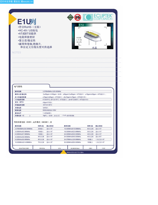
E1UAA20-16.257M中文资料(ECLIPTEK)中文数据手册「EasyDatasheet - 矽搜」
E1U列•符合RoHS(无铅)•HC-49 / US短包•AT或BT切提供•电阻焊接密封•紧公差/稳定性•磁带和卷轴,绝缘片,和自定义引线长度可供选择NOTES H 2.50L 11.18W 4.70水晶_____________________________________________________________________________________________________________________________________________________________________________________________ _____________________________________________________________________________________________________________________________________________________________________________________________ _____________________________________________________________________________________________________________________________________________________________________________________________ _____________________________________________________________________________________________________________________________________________________________________________________________ _____________________________________________________________________________________________________________________________________________________________________________________________ _____________________________________________________________________________________________________________________________________________________________________________________________ _____________________________________________________________________________________________________________________________________________________________________________________________ _____________________________________________________________________________________________________________________________________________________________________________________________ _____________________________________________________________________________________________________________________________________________________________________________________________ _____________________________________________________________________________________________________________________________________________________________________________________________ _____________________________________________________________________________________________________________________________________________________________________________________________ _____________________________________________________________________________________________________________________________________________________________________________________________电气特性频率范围频率公差/稳定性在工作温度范围温度范围工作温度范围老化(25°C)存储温度范围并联电容绝缘电阻驱动电平负载电容(C)3.579545MHz为50.000MHz为±50ppm /±100ppm(标准),±30ppm/为±50ppm(AT切割只),±15ppm/±30ppm(AT切割只),±15ppm/±20ppm(AT切割只),或±10ppm/±15ppm(AT切割专用)0°C到70°C,-20°C至70°C(AT切割只),或-40°C至85°C(AT切割专用)±5ppm/年最大-40°C至125°C7pF最大500兆欧最低在100V1 mWatt最大18pF之(标准),自定义C 10pF,或串联谐振等效串联电阻(ESR),运作模式(MODE),切频率范围3.579545MHz到4.999MHz5.000MHz到5.999MHz6.000MHz到7.999MHz8.000MHz到8.999MHz9.000MHz到9.999MHz10.000MHz到14.999MHz ESR (Ω)200最大150最大120最大90马克斯80马克斯70马克斯模式/剪切基本/ AT基本/ AT基本/ AT基本/ AT基本/ AT基本/ AT频率范围15.000MHz到15.999MHz16.000MHz到23.999MHz24.000MHz到30.000MHz24.000MHz到40.000MHz24.576MHz为29.999MHz30.000MHz到50.000MHzESR (Ω)60马克斯50马克斯40马克斯40马克斯150最大100最大模式/剪切基本/ AT基本/ AT基本/ AT基本/ BT三次泛音/ AT三次泛音/ AT.ECLIPTEK CORP.CRYSTAL E1U HC-49/US Short CR4111/07零件编码指南E1U A A 18 - 20.000M - I2 TR频率公差/稳定性A =±50PPM 25°C时,±0℃至100ppm70℃B =±50PPM,在25°C,±100ppm-20℃至70℃C =±50PPM,在25°C,±100ppm温度范围为-40°C至85°CD =±30ppm25°C时,±0℃50PPM至70℃E =±30ppm25°C时,为±50ppm -20℃至70℃F =±30ppm25°C时,为±50ppm -40°C至85°CG =±15ppm25°C时,±0℃为30ppm至70℃H =±15ppm25°C时,±30ppm-20℃至70℃J =±15ppm25°C时,±30ppm温度范围为-40°C至85°C K =±15ppm25°C时,±0℃为20ppm至70℃L =±15ppm25°C时,±20ppm-20℃至70℃M =±15ppm25°C时,±20ppm温度范围为-40°C至85°C N =±10ppm25°C时,±0℃为15ppm至70℃P =±10ppm25°C时,±15ppm-20℃至70℃包装选择空白=散装,A =盘,TR =卷带式可选项空白=无(标准)CX =自定义引线长度I2 =绝缘子标签频率负载电容S =系列X X = X X pF(自定义)动作模式/水晶切割A =基本/ A TB =三次泛音/ A TD =基本/ BT外形尺寸ALL DIM ENSIONS IN M ILLIM ET ERS 卷带尺寸ALL DIM ENSIONS IN M ILLIM ET ERS环境/机械特性PARAMET ER SPECIFICAT ION 标记规格1000 Pieces per ReelCompliant to EIA-468B精细泄漏测试总泄漏测试铅完整铅端接机械冲击耐焊接热抗溶剂可焊性温度循环振荡M IL-STD-883,方法1014,条件AM IL-STD-883,方法1014,条件CM IL-STD-883 2004方法锡2微米 - 6微米M IL-STD-202,方法213,条件CM IL-STD-202,方法210M IL-STD-202,方法215M IL-STD-883,2002年法M IL-STD-883,法1010M IL-STD-883,方法2007,条件A1号线:电子X X.X X X中号Frequency in MHz(5 Digits Maximum + Decimal).ECLIPTEK CORP.CRYSTAL E1U HC-49/US Short CR4111/07。
唯特利管道Vic-Strainer过滤器安装手册说明书

2. 转动过滤器滤篮: 必要时,转动过滤器滤篮,使伸出过滤器器体的 长度最短。
3. 遵照“接头安装”一节的程序进行连接。
2. 安装检修盖、密封垫圈和接头:将检修盖和密封垫圈安裝到 Vic-Strainer器体上。确保密封垫圈Vic-Strainer器体上的沟 槽与检修盖之间对中就位。
2a. 利用“剪合”作用,将本体包裹密封垫圈安装。确保本体键咬合到 Vic-Strainer过滤器本体上的沟槽和检修盖的外表面上。
1. 检查密封垫圈并对其进行润滑: 检查密封垫圈是否损坏或磨损。 如果密封圈已损坏或磨损,请用一个唯特利提供的相同等级的新密 封圈更换。在密封垫圈密封唇缘及其外表面涂敷一薄层唯特利润滑 剂或硅树脂润滑剂。切勿在E级密封垫圈上使用石油基润滑剂。
1. 定位放置过滤器滤篮: 让过滤器滤篮切有斜角的一端对好方向, 以便正确地插入器体中,如上图所示。
C修订版
I-730/732/AGS-CHI_1
安装与维修方法说明
Vic-Strainer®
730与
W730系列T型VIC-STRAINER过滤器
732与
W732系列Y型VIC-STRAINER过滤器
安装
说明
• 以下步骤的数步中采用了732系列Y型Vic-Strainer过滤器照片。 然而,同样的步骤一样适用于W732系列AGS Y型Vic-Strainer 过滤器、730系列T型Vic-Strainer过滤器和W730系列AGS T型 Vic-Strainer过滤器,另有说明者除外。
12.750 323.9
14.000 355.6
16.000 406.4
18.000 457.0
20.000 508.0 24.000 610.0
螺纹加工简介-THREADING

ECO_Gewindebohrer_deECO_Gewindebohrer_deTapping technologyDry tappingCoatings for DRY/ML-TAPPINGDry tapping(ML-quantity for tapping: 20...50 ml/h)Coatings for DRY/ML-TAPPINGTHL TINTIN, new tap TIN, wornout tap THL, new tap THL, wornout tapTIN THL ECO_Gewindebohrer_deTap design for internal ML-supplyLaser-welded pinDesigned foroptimised ML-flowECO_Gewindebohrer_de11HSC -tappingHSC -threadingthread M8C45, blind hole, 2 x D n = 1.671 Rpm pitch = 1,250timeCollet holder (no floating)MD (Nm)circa 10 N70-100 Ntorque, axial forceAxial-force (N)SYNCHROFLEX? ECO_Gewindebohrer_deHSC -Synchronised tapping testSolid carbide threading toolsMachining exampleSolid carbide threading toolsECO_Gewindebohrer_deThread formingI. Thread FormationAxial flowTangentialRadial flow flowECO_Gewindebohrer_de23GewindeformenECO_Gewindebohrer_de25Formed threadsXC18XC18Bronze Bronze XC42XC42Brass Brass XC70XC70AlSi13AlSi13RostfreiRostfrei AlCu4MgAlCu4MgECO_Gewindebohrer_de26Tensile strength of formed threads5010015020025030035001002003004005006007008009001000Distance from the root (m)M i c r o H a r d n e s s H VXC18XC42XC70Stainless Steel Bronze BrassAlSi13AlCu4MgH(m)HV 0,1for non-ferrous materialsECO_Gewindebohrer_de27050010001500200025003000350040005101520253035404550Number of lobe having workedM z T o r q u e (N .c m )Tap entranceEmulsionOilLast lobe in the tap enteringMaterial : XC70Tool : Protodyn S M12*1,5 11,32 mm V = 14 m/min Oil TFE Valona MS 70095% water based emulsion MobilCut 151F o r m a t i o n t o r q u e+ 55%+ 34%Friction torqueInfluence of coolantThread forming with ML(ML-quantity for forming: 20...50 ml/h)ECO_Gewindebohrer_deGeometry descriptionThread milling cutterchamfer cutting partBore for central internal cooling60ˆdriving flatd1 l2 l1shankd2d1 = diameter of thread d2 = diameter of shankl1 = total length l2 = length of cutting edgesECO_Gewindebohrer_de31Function of thread milling 1 (90ˆ driven in)1/4P 1P 1/4PMove above the core- holeMove into the Radial Thread milling centre of the adjustment 360ˆ- helix hole to depth of cut with synchron in a tangential axial feed curve (90ˆ) (pitch)ECO_Gewindebohrer_deMove clear of the contour in radial direction (90ˆ)Move out of the thread hole32Thread milling in two stepsWith a two and three times cut subdivision the lateral adjustment is calculated at the material removal. With two cuts, it is in each case 1/2 of the material removal. With three cuts, it is in each case 1/3 of the material removal.1st cut3/4 of profile2nd cut1/4 of profileECO_Gewindebohrer_de3433Advantages of thread millingPossible to reduce the variety of toolsvarying sized threads with same pitch Possible to make blind holes and through holes with the same tool Possible to make left-hand and right-hand threads with the same toolCan process high-tensile or difficult-to-machine materials using a standard tool dry machining (absolutely dry or ML) is no problem in all materials, but sometimes it can make sense to use just air or ML for chip evacuationECO_Gewindebohrer_de 34Left-hand / right-hand threadsd an -h ht ig ad R re thFrom top to bottom in downcutFrom top to bottom in upcutd an -h ht ig ad R re thFrom bottom to top in upcutFrom bottom to top in downcutECO_Gewindebohrer_de 35Advantages of thread millingTechnically-related advantages by means of: thread production without leadThread tappingDepth of hole Depth of hole Depth of thread Lead ~3 threads Safety ~2 threadsThread millingDepth of threadExactly defined depth of thread Greater process security due to short chip formation Threads with pitched run-ins / run-outs possible Tool breakage doesnˆt immediately lead to rework of the component or scrapECO_Gewindebohrer_de36Combination Drilling + thread milling1 20.5 x p p3Create core hole, only axial movementRetract by around 2* pitch and then tangential run-in in an arcThread milling 360ˆ helix with synchronous axial feed in pitchStart455 2 3 14Radial run-in to thread centre tangentially out of the contour Axial run-out from the threadECO_Gewindebohrer_de 37Thread milling in a helix1 2 3pStarting position centrally over the threadRadial feed to required radiusIn one screw line thread milling with simultaneous drilling4515 2Linear into the thread centreAxial run-out out of the threadECO_Gewindebohrer_de4338Where are we with Rprog - 6H?Flank diameter - maximum size on component 11,216 11,206 11,196 11,186 11,176 11,166 11,156 11,146 total 11,136 R¡äp og - 0 04 r . tolerance 11,126 11,116 11,106 11,096 11,086 11,076 11,066 R¡äp og ze oli n r r 11,056 11,046 11,036 11,026 Flank diameter - smallest size on componentnominal diameterlength of threadpitchradius of cutting edges (tool correction value)ECO_Gewindebohrer_de39Costs comparisonSteel 42CrMo4, 800 N/mm2 internal , thread, blind hole, 2xD deepMachine: BAZ, IK existent, Synchronous thread cutting up to max. 2.500 rev/min Emulsion 10%, Hourly rate - 100 EuroM8, blind hole, 42CrMo4, 800 N/mm290M4, blind hole, 42CrMo4, 800N/mm2Costs per thread (Cent) . 100 80 60 40 20 0 PARADUR ECO HT Cutting PROTODYN ECO Contouring GFR H50 51108 MillingM12, blind hole, 42CrMo4, 800 N/mm2Costs per thread (Cent).80 70 60 50 40 30 20 10 0 PARADUR ECO HT i.K. Cutting PROTODYN ECO i.K. Contouring GFR H50 41118 i.K. MillingCosts per thread (Cent).90 80 70 60 50 40 30 20 10 0 PARADUR ECO HT i.K. Cutting PROTODYN ECO i.K. Contouring GFR H50 41118 i.K. MillingECO_Gewindebohrer_de40SummaryThis document was created with Win2PDF available at . The unregistered version of Win2PDF is for evaluation or non-commercial use only.。
- 1、下载文档前请自行甄别文档内容的完整性,平台不提供额外的编辑、内容补充、找答案等附加服务。
- 2、"仅部分预览"的文档,不可在线预览部分如存在完整性等问题,可反馈申请退款(可完整预览的文档不适用该条件!)。
- 3、如文档侵犯您的权益,请联系客服反馈,我们会尽快为您处理(人工客服工作时间:9:00-18:30)。
In compliance with our End of Life (EOL) policy, this will serve as advanced notice of product termination. New orders will not be accepted after July 28th, 2008, with delivery to conclude by October 28th, 2008. If there are any questions pertaining to this bulletin, please feel free to contact me. Thank you again for your cooperation.
Best Regards,
Isaac Gonzalez Configuration Manager Ecliptek Corporation
3545 CADILLAC AVENUE • COSTA MESA, CA 92626-1401 • (714) 433-1200 • Fax (714) 433-1234
_____________________________________________________________________________________________________________________________________________________________________________________________ _____________________________________________________________________________________________________________________________________________________________________________________________
OBSOLETE
_____________________________________________________________________________________________________________________________________________________________________________________________ _____________________________________________________________________________________________________________________________________________________________________________________________
_____________________________________________________________________________________________________________________________________________________________________________________________ _____________________________________________________________________________________________________________________________________________________________________________________________
元器件交易网
Marketing Bulletin
DATE: TO: FROM: RE: January 28th, 2008 All Sales Personnel Isaac Gonzalez Product Termination
To all concerned parties, This bulletin is to notify all customers of the discontinuation of the following Ecliptek series effective January 28th, 2008: Series EC3 Description Resistance Welded HC-49/UST Crystal Recommended Replacement E2S
EQUIVALENT SERIES RESISTANCE (ESR), MODE OF OPERATION (MODE), AND CUT
Frequency Range 3.579545MHz to 4.999MHz 5.000MHz to 5.999MHz 6.000MHz to 7.999MHz 8.000MHz to 8.999MHz 9.000MHz to 9.999MHz 10.000MHz to 14.999MHz ESR (Ω) 200 Max 150 Max 120 Max 90 Max 80 Max 70 Max Mode / Cut Fundamental / AT Fundamental / AT Fundamental / AT Fundamental / AT Fundamental / AT Fundamental / AT Frequency Range 15.000MHz to 15.999MHz 16.000MHz to 23.999MHz 24.000MHz to 29.4912MHz 24.000MHz to 40.000MHz 28.6363MHz to 29.999MHz 30.000MHz to 50.000MHz ESR (Ω) 60 Max 50 Max 40 Max 40 Max 150 Max 100 Max Mode / Cut Fundamental / AT Fundamental / AT Fundamental / AT Fundamental / BT Third Overtone / AT Third Overtone / AT
_____________________________________________________________________________________________________________________________________________________________________________________________ _____________________________________________________________________________________________________________________________________________________________________________________________
元器件交易网
EC3 Series
• HC-49/UST package • AT or BT cut available • Resistance weld seal • Tight tolerance/stability • Insulator tab, and custom lead length options available
元器件交易网
PART NUMBERING GUIDE EC3 A - T - 20 - 30.000M - I2
FREQUENCY TOLERANCE / STABILITY Blank=±50ppm at 25°C, ±100ppm from 0°C to 70°C A=±50ppm at 25°C, ±100ppm from -20°C to 70°C B=±50ppm at 25°C, ±100ppm from -40°C to 85°C C=±30ppm at 25°C, ±50ppm from 0°C to 70°C D=±30ppm at 25°C, ±50ppm from -20°C to 70°C E=±30ppm at 25°C, ±50ppm from -40°C to 85°C F=±15ppm at 25°C, ±30ppm from 0°C to 70°C G=±15ppm at 25°C, ±30ppm from -20°C to 70°C H=±15ppm at 25°C, ±30ppm from -40°C to 85°C J=±15ppm at 25°C, ±20ppm from 0°C to 70°C K=±15ppm at 25°C, ±20ppm from -20°C to 70°C L=±15ppm at 25°C, ±20ppm from -40°C to 85°C M=±10ppm at 25°C, ±15ppm from 0°C to 70°C N=±10ppm at 25°C, ±15ppm from -20°C to 70°C AVAILABLE OPTIONS Blank=None (Std) CL150=Custom Lead Length (See Page 42) CL175=Custom Lead Length (See Page 42) I2=Insulator Tab (See Page 42) FREQUENCY LOAD CAPACITANCE Blank=18pF (Standard), S=Series XX=XXpF (Custom) MODE OF OPERATION / CRYSTAL CUT Blank=Fundamental / AT, B=Fundamental / BT T=Third Overtone / AT
_____________________________________________________________________________________________________________________________________________________________________________________________ _____________________________________________________________________________________________________________________________________________________________________________________________
