A novel control strategy for a variable speed wind turbine with a permanent magnet synchronous
单相光伏并网逆变器控制技术

图 4 中 ,G1 (s) = Kp +
Ki s
,G2 (s) = Kpwm,G3 (s) =
1 L1s+r1
,G4(s)=
1 Cs
,G5(s)=
1 L2s+r2
。
则其传递函数为:
H(s)= ig(s) = Δi(s)
G1(s)G2(s)G3(s)G4(s)G5(s)
(8)
1+ G2(s)G3(s)+G3(s)G4(s)+G4(s)G5(s)
些,这样不仅容易调试,而且有利于减小系统的跟踪 误差,如图 3 所示。 图中,ΔUg 为电网扰动信号,Gg(s) 为扰动补偿器,GDSP、Ginv(s)、GLCL(s)分别为 DSP、逆变 器和滤波器的增益函数。
iref + -
GDSP + -
Gg(s) Ginv(s)
+
ΔUg - Δig(s) GLCL(s) ig
图 1 中,主电路包括光伏阵列 PV、DC / DC 变换器、 DC / AC 逆变器、LCL 滤波器及相应的控制单元[8-9]。 本文的控制思想是 在 Boost DC / DC 电 路 中 通 过 最 大功率点跟踪控制方法控制开关管的占空比,从而 跟踪光伏电池输出最大功率时的电池端电压 uc, 并 在 DC / AC 并网逆变控制中,以 i*pv 为逆变器控制的瞬 时参考电流,i*pv 是以光伏电 池 最 大 功 率 跟 踪 输 出 的 直流电流 Imax 作为其峰值,以电网电压的相位和频率 作为其相位和频率。 因此,该控制方法既能使并网 逆变器跟踪电网的频率与相位,又能向电网实时输 送最大功率,实现最大功率点跟踪;另外,为了确保 控制系统的稳定,还引入了电网电压前馈控制和滤 波电容电流内环控制的思想。 传统的逆变器是通过 LC 滤波器来衰减逆变器输出电流中存在的谐波分量,
毕业设计风力发电外文文献
Abstract--The purpose of this paper is to find an innovative, high efficiency, practical and low cost control system structure with an optimized control strategy for small-scale grid-connected wind turbine with direct-driven permanent magnet synchronous generator (PMSG). This research adopts the sensorless vector control strategy based on phase-locked loop (PLL) for PMSG control, and the grid-side inverter control strategy is based on the single-phase PLL. The simulation demonstrates that the sensorless control strategy and single-phase grid-side inverter control strategy are practical solutions for grid-connected PMSG wind turbines, and they can provide both generator speed control for optimized wind power tracking and good power quality control for electricity delivered to the grid. The designed system offers many unique advantages, including simple topology, optimized control strategy, cost-effective and fast respond to grid failures.Index Terms--Maximum power point tracking (MPPT), PMSG, pulse-width modulation (PWM) converter, speed control, variable-speed wind turbine.I. I NTRODUCTIONn recent years, great attention has been paid on renewable energy sources, such as wind and solar energy. Wind energy is the most popular renewable energy source due to its relatively low cost. The overall system cost can be further reduced by optimal control of high efficiency power electronic converters to extract maximum power in accordance with atmospheric conditions [11].The wind energy conversion system based on permanent magnet synchronous generator (PMSG) is one of the most favorable and reliable methods of power generation. Reliability of variable-speed direct-driven PMSG wind turbines can be improved significantly comparing to doubly-fed induction generator (DFIG) wind turbines with gearboxes. Noise, power loss, additional cost, and potential mechanical failure are typical problems for a DFIG wind turbine because of the existence of a gearbox. The use of direct-driven PMSG could solve these problems. Moreover, low voltage ride through (LVRT) is also a big issue for DFIG because the This work was supported in part by the special funds from Beijing Municipal Education Commission.Chunxue Wen, Guojie Lu, Peng Wang and Zhengxi Li are with the Power Electronics and Motor Drivers Engineering Research Centre, North China University of Technology,Beijing,China(e-mail: wenchx1980@, lugod307@, catdapeng2008@, lzx@).Xiongwei Liu and Zaiming Fan are with the School of Computing, Engineering and Physical Sciences, University of Central Lancashire, Preston, PR1 2HE, UK (e-mail: xliu9@, zmfan@) electromagnetic relationship between the stator and the rotor is more complex than PMSG. Therefore, it’s more difficult for DFIG to solve LVRT problem safely and reliably.In a variable-speed PMSG system, vector control approach is often used to achieve nearly decoupled active and reactive power control on the grid-side inverter which is a current regulated voltage source inverter. In this way, the power converter maintains the DC-link voltage and improves the power factor of the system [1], [7], [10]. Different control methods for maximum power point tracking (MPPT) in variable-speed wind turbine generators have been discussed in [2], [4], [7].This research adopts the sensorless vector control strategy based on phase-locked loop (PLL) for PMSG control [2]. The method requires only one active switching device, i.e. insulated-gate bipolar transistor (IGBT), which is used to control the generator torque and speed so as to extract maximum wind power. It is a simple topology and low cost solution for a small-scale wind turbine because of the sensorless vector control strategy. The grid-side inverter control strategy is based on the single-phase PLL, which applies a control method in Direct-Quadrature (DQ) rotating frame to single-phase inverter and achieves superior steady state and dynamic performance [6].For small-scale wind turbine, single-phase power supply to consumers is popular. There are many control methods for single-phase inverter, such as PI controller, quasi-PR controller, etc. [5]. However, these methods can’t decouple the active power and reactive power so as to have good power control performance. Single-phase PLL method based on DQ rotating frame can well solve this problem. On the other hand, encoders are vulnerable components for wind turbines, particularly for small wind turbines, because small wind turbines experience severer vibrations than their large counterparts. The sensorless vector control opts out the encoders, and therefore the reliability of wind turbines is much improved. For these reasons, the sensorless vector control and single-phase PLL method have their unique advantages for small-scale wind turbines.This paper is structured further in following three sections. In section II, the principle of the full power back-to-back PWM converter is introduced. Then the vector control of small-scale grid-connected wind power system including sensorless control, vector control of PMSG, single-phase PLL, vector control of grid-side inverter are described in section III. Finally, in section IV, the simulation results and conclusion are given.Vector control strategy for small-scale grid-connected PMSG wind turbine converter Chunxue Wen, Guojie Lu, Peng Wang, Zhengxi Li Member IEEE, Xiongwei Liu Member IEEE,Zaiming Fan Student Member IEEEIII. T HE PRINCIPLE OF FULL POWER BACK-TO-BACK PWMCONVERTERTypical topology model of direct-driven PMSG wind turbine is shown in Fig. 1. Converters of the system adopt back-to-back pairs of pulse-width modulation (PWM) architecture. The generator-side converter controls the generator speed in order to achieve maximum capture of wind power, and the grid-side inverter controls the stability of DC-bus voltage and the power factor of the system. This topology can be a good way to improve performance, and the control method is flexible. Converters have four-quadrant operation function, which can fulfill the generator speed control anddeliver the fine quality of electricity to the grid [7], [8].Fig. 1. Topology of permanent magnet direct-driven wind power systemIII. T HE VECTOR CONTROL OF SMALL-SCALE GRID-CONNECTEDDIRECT-DRIVEN WIND POWER SYSTEM CONVERTERFig. 2 shows the back-to-back PWM voltage convertervector control block diagram. The machine-side PWMconverter controls the electromagnetic torque and statorreactive power (reactive power is often be set to 0) byadjusting the current of the d-axis and q-axis of the machine-side converter. This control mechanism helps the PMSG tooperate in variable speed, so that the wind turbine can workwith maximum power point tracking (MPPT) under the ratedwind speed. The grid-side PWM inverter stabilizes the DC-busvoltage and accomplishes active and reactive decouplingcontrol by adjusting the current of the d-axis and q-axis of thegrid-side. The grid-side PWM inverter also controls thereactive power flow to the grid, usually at unity power factorcondition.A. Sensorless control based on PLLThe speed and position control is achieved throughsensorless vector control of the machine-side converter basedon all-digital phase-locked loop. The phase-locked loop isdesigned to control the frequency of the D-Q axis voltagethrough minimizing the difference of the output voltage phaseangle and the given voltage phase angle, until the outputvoltage phase angle tracks the given voltage phase angle. Asthe phase-locked loop has frequency closed-loop trackingmechanism, the generator voltage frequency and the anglebetween d-axis voltage and rotor flux can be measured withthis characteristic, then the generator speed and rotor positionangle can be derived [2]. The control accuracy is generallygood using this method, however some problems may occurwhen the generator operates at very low speed. The windpower system often works above the cut-in wind speed, so thismethod can be applied to wind power generation system.Fig. 2.The back-to-back PWM voltage converter vector control block diagramThe actual rotor position of PMSG is indicated in the D-Q coordinate system. The estimated location for ∧θ is the d q ∧∧− coordinate system, αβ is the stationary coordinate system, as shown in Fig. 3. As the rotor position of PMSG is estimated rather than measured in the sensorless vector control system, there exists an error θΔ between the actual rotor position θ and the estimated location ∧θ. At the same time, the back-EMF (electromotive force) generated by the rotor permanent magnets generates two d-axis and q-axis components in the estimated rotor position orientation coordinates, which are expressed as sd e ∧and sq e ∧respectively. Conventional PI controller can achieve zero error control, i.e. sd e ∧or θΔ can be adjusted to zero value. The PLL sensorless vector control schematic diagram is shown in Fig. 4, and the value of sd e ∧and sq e ∧can be obtained from (1).sd sd s sd dq sq sd sq sq s sq q d sd sq di u R i L L i e dt di u R i L L i e dt ωω∧∧∧∧∧∧⎧=+−−⎪⎪⎨⎪=+++⎪⎩(1)Fig. 3. Presumed rotating coordinate systemFig. 4. Principle of PLL based sensorless vector controlIf we ignore the current differential items in (1), then wehavesd s sd q sq sd sq sq s sq d sd ˆˆˆˆˆarctan(arctan(ˆˆˆˆˆu R i L i ee uR i L i ωθω−+Δ=−=−−− (2)where sd u , sq u , sd i and sq i are the d, q-axis components of the output voltage and current of the generator stator; d L q L and s R are the inductance and resistance of the stator; ω is thegenerator electrical angular velocity of the generator; "∧" indicates estimated value.Block diagram of sensorless vector control based on digital PLL is shown in Fig. 5. The back-EMF (electromotive force) value of the estimated rotating coordinates can be obtained by calculating the three-phase voltages and currents of the PMSGstator. The calculated angle difference θΔcan be used to estimate the angular velocity through the PI controller. Then the value of the estimated angle can be obtained by integral element. Generally, the speed has considerable fluctuations using this method. Therefore it will achieve a better estimation by adding a low-pass filter (LPF), as shown in Fig. 5.∧Fig. 5. Block diagram of sensorless vector control based on digital PLLB. Vector control of PMSGIn order to study the torque control of PMSG, it is necessary to establish a mathematical model. Because q-axis leads d-axis 90° in the D-Q coordinate system, the generator voltage equation can be expressed as [8]: sd sd s sd d sq sq sq sq sq q d sd di u R i L L i dt di u Ri L L i dt ωωωψ⎧=+−⎪⎪⎨⎪=+++⎪⎩(3) The significance of various physical quantities in (3) is the same as in (1).The generator electromagnetic torque equation can be expressed as:33()22e sq d q sd sq T p i p L L i i ψ=+− (4) where p is the number of generator pole pairs, and ψ is the magnetic flux.Based on the above mathematical model, the sensorless vector control program of PMSG is established, and its controlblock diagram is shown in Fig. 6.sa i sbi Fig. 6. Sensorless vector control block diagram of PMSGGenerator rotor position and speed which are estimated by sensorless algorithm can be used in vector control. Thereference value of motor torque can be obtained by the speedcontroller. The voltage reference of generator can also be gotby current controller, and then the control signals of rectifier switching device can be obtained by a set of PWM modulation algorithms. The position and speed of generator rotor which is necessary to vector control is obtained by sensorless algorithm.C. Single-phase grid-connected PLLFig. 7 shows the block diagram of the single-phase gird-connected PLL. In order to ensure that the converter outputvoltage is in the same phase with the output current, the PLLis used to achieve unity power factor control. At the sametime, the converter also provides the angle of the referencecurrent transformation [5].Fig. 7. The block diagram of the single-phase PLLThe transformation between orthogonal a-b and D-Q reference frames can be described by trigonometric relations, which are given in (5) and (6), and the rotating reference frame is shown in Fig. 8.Fig. 8. Definition of rotating reference frame⎥⎦⎤⎢⎣⎡⎥⎦⎤⎢⎣⎡−=⎥⎦⎤⎢⎣⎡b a q d f f f f θθθθcos sin sin cos (5) ⎥⎦⎤⎢⎣⎡⎥⎦⎤⎢⎣⎡−=⎥⎦⎤⎢⎣⎡q d b a f f f f θθθθcos sin sin cos (6)Active power and reactive power equations can beexpressed as:⎩⎨⎧−=+=d q q d qq d d i v i v Q i v i v P (7) If the phase voltage and q-axis coincide, then 0=d v andv v q =, active power and reactive power equations can besimplified as:||||q dP v i Q v i =⎧⎪⎨=−⎪⎩ (8) D. The vector control strategy of the grid-side inverterFor a three phase converter, simple PI compensators designed in a D-Q synchronous frame can achieve zero steady state error at the fundamental frequency, but this method is not applicable to single-phase power converter because there is only one phase variable available in a single-phase power converter, while the D-Q transformation needs at least two orthogonal variables.In order to construct the additional orthogonal phaseinformation from the original single-phase power converter,the imaginary orthogonal circuit is developed, as shown inFig. 9. The imaginary orthogonal circuit has exactly the samecircuit components and parameters, but the current b i and the voltage b e , maintain 90D phase shift with respect to their counterparts in the real circuit- a i and a e [6].Fig. 9. Real circuit and its imaginary orthogonal circuitFrom Fig. 9, the voltage equation can be expressed as:⎥⎦⎤⎢⎣⎡−−+⎥⎦⎤⎢⎣⎡⎥⎦⎤⎢⎣⎡−=⎥⎦⎤⎢⎣⎡b b a a b a b a v e v e L i i L R i i p 11001 (9) Transforming the voltage equations into the synchronousreference frame using (5) and (6), and considering 0=d v and v v q =, we have: ⎥⎦⎤⎢⎣⎡−+⎥⎦⎤⎢⎣⎡⎥⎦⎤⎢⎣⎡−−−=⎥⎦⎤⎢⎣⎡||1//v e e L i i L R L R i i p qd q d q d ωω (10) To achieve decoupled control of active power and reactive power, the output voltage of the inverter in the synchronousreference frame can be expressed as:||)(1v i x L e d q +−=ω (11))(2q d i x L e ω+= (12)Substituting (11) and (12) into (10), system equations canbe rewritten as follows:⎥⎦⎤⎢⎣⎡+⎥⎦⎤⎢⎣⎡⎥⎦⎤⎢⎣⎡−=⎥⎦⎤⎢⎣⎡211001x x i i L R i i p q d q d (13) The active power and reactive power could be controlled by d i and q i respectively. Therefore, system control can be completed by current feedback loops as follows:))((211q q i i s k k x −+=∗(14)))((212d d i i sk k x −+=∗(15) Fig. 10 shows the control block diagram of the grid-sideinverter. It should be noted that the given active and reactive power should be set at two times of the desired values, because the imaginary circuit will not deliver any active andreactive power to the grid.θωFig. 10. The vector control block diagram of the grid-side inverterIV. S IMULATION RESULTSA simulation model in Matlab/Simulink is developed based on above theoretical analysis, and the system simulation block diagram is shown in Fig. 11.Fig. 11. The system simulation block diagramA. The simulation results of the machine-side converterIn the simulation model, the Reference speed represents the wind speed. At the beginning of the simulation (i.e. 0s), the generator speed is 4rpm and its input torque is -50Nm. At the time of 0.5s, the generator speed is 17 rpm and the input torque maintains at the value of -50Nm. At 1s, the generator speed maintains at 17 rpm and the input torque is -80Nm. The simulated waveforms are shown in Fig. 12, Fig. 13, Fig. 14, Fig. 15, respectively.It can be seen from Fig. 12 and Fig. 13, the error between the estimated rotor position angle and the actual measurement of the rotor position angle is very small in the steady state, there are some fluctuations in the dynamic response, but the rotor position angle is stabilized quickly.It can be seen from Fig. 14 and Fig. 15, there is a small error between the estimated and measured generator rotor speed at low speed. At high speed, however, the error is very small and can be ignored, and the transient response is very short. At the time 1s, the input torque increase affects thegenerator rotor speed slightly, and soon the transientdisappears.ˆ,(d e g )θθ()t sFig. 12. The estimated and measured rotor position angle(rad/s)θθ∧−(s)tFig. 13. The error of estimated and measured rotor position anglet(s)()nrpmFig. 14. The measured generator rotor speedt(s)t()esirpmnFig. 15. The estimated generator rotor speedThe simulation waveforms of the machine-side converterdemonstrate that the sensorless vector control algorithm canestimate the rotor angular position accurately, and the vectorcontrol strategy of the machine-side converter can realizegenerator speed control for the wind turbine to follow theoptimized power curve, i.e. MPPT when the wind speed isbelow rated wind speed.B. The simulation results of the grid-side inverterThe simulation results of the grid-side inverter is shown inFig. 16, Fig. 17 and Fig. 18 respectively.It can be seen from Fig. 16, when the generator outputtorque increases, the DC bus voltage is maintained constant.Fig. 17 shows that θu followsavvery well, and Fig. 18shows thatai followsavvery well.Fig. 16. The simulated DC voltageavuθuθFig. 17. The generator output A phase voltage and the grid voltage vectorangleFig. 18. The output voltage and current of the grid-side inverterFrom the simulation results of the grid-side inverter, it canbe seen that the single-phase PLL algorithm can accuratelytrack the grid-side voltage, and the vector control strategy ofthe grid-side inverter can stabilize the DC bus voltage, andcontrol the grid power factor.V. C ONCLUSIONThis research developed a power electronic converter for asmall direct-driven PMSG wind turbine using the back-to-back pulse-width modulation (PWM) topology. Thesimulation results demonstrate that1) The machine-side converter can control the generatorspeed and torque for the wind turbine to follow the optimizedpower curve, i.e. maximum power point tracking (MPPT)when the wind speed is below rated wind speed.2) The sensorless phase-locked loop (PLL) controlalgorithm can realize the vector control of the generator.3) The grid-side inverter control algorithm based on single-phase PLL can stabilize the DC bus voltage of the converter and control the grid power factor.VI. R EFERENCESPeriodicals:[1]De Tian, “The wind power technology status and development trend inthe world,” New Energy Industry, in press.[2]Ruzhen Dou, Lingyun Gu, Baotao Ning, “Sensorless control of thePMSM based on the PLL,” Electric Machines & Control Application, vol. 32, pp. 53-57, 2005.Books:[3]Qingding Guo, Yibiao Sun, Limei Wang, Modern permanent magnet ACservo motor system. China Electric Power Press, Beijing. In press.Papers from Conference Proceedings (Published):[4]S. Song, S. Kang, and N. Hahm, “Implementation and control of gridconnected AC-DC-AC power converter for variable speed wind energy conversion system,” in Proc. 2003 IEEE Applied Power Electronics Conference and Exposition, vol.1, pp.154 – 158.[5]M. Ciobotaru, R. Teodorescu and F. Blaabjerg, “A new single-phasePLL structure based on second order generalized integrator,” Record of IEEE PESC 2006, Korea, pp.1511-1516.[6]R. Zhang, M. Cardinal, P. Szczesny, M. Dame, “A grid simulator withcontrol of single-phase power converters in D-Q rotating frame,” Power Electronics Specialists Conference, vol.3, pp.1431 – 1436, 23-27 June 2002.[7]R. Esmail, L. Xu, D.K. Nichols, “A new control method of permanentmagnet generator for maximum power tracking in wind turbine application,” IEEE Power Engineering Society Meeting, vol.3, pp. 2090-2095, August 2005.[8]Yang Zhenkun, Liang Hui, “A DSP control system for the gridconnected inverter in wind energy conversion system,” IEEE ICEMS 2005 Electrical Machines and Systems, vol. 2, 2005, pp. 1050-1053, June 2005.[9]N V Suresh Kumar Srighakollapu, Partha Sarathi Sensarma, “Sensorlessmaximum power point tracking control in wind energy generation using permanent magnet synchronous generator,” Industrial Electronics 2008, 34th Annual Conference Of IEEE, Iecon , pp.2225-2230.Dissertations:[10]Cheng Lu, “The coordination control of dual PWM converter for VSCFwind power generation system,” MSc thesis, Graduate School of Chinese Academy of Sciences, Beijing, 2004.[11]Shenbing Wu, “Research on CSC-based small-scale grid-connectedwind power generation system”, MSc thesis, Hefei University of Technology, Hefei, 2009.VII. B IOGRAPHIESChunxue Wen received his BSc degree from Inner Mongolia University of Technology in 2001, MSc degree from Wuhan University in 2006, and PhD degree from the Institute of Electrical Engineering, Chinese Academy of Sciences in 2009. In 2010 he joined the Wind Energy Engineering Research Group at the University of Central Lancashire as a visiting researcher. He is currently working as a Lecturer at the Power Electronics and Motor Drivers Engineering Research Center, North China University of Technology, Beijing, China. His research interests include power electronics, wind turbine control system, converters for wind turbines.Guojie Lu received his BSc degree from North China Electric Power University in 2006. He worked in Beijing Xinhuadu Special Transformer Company from 2007 to 2009, and was responsible for the technical service transformer. At present, he is registered as a postgraduate research student at the Power Electronics and Motor Drivers Engineering Research Center, North China University of Technology, Beijing, China. His research area is wind turbine control system.The project aims to develop maximum power point tracking control algorithm for grid-connected small wind turbines.Peng Wang received his BSc degree from Taiyuan University of Technology in 2003, MSc degree from North China University of Technology in 2011. Since 2008, he has been working as a research assistant in Electrical Engineering at the Power Electronics and Motor Drivers Engineering Research Center, North China University of Technology, Beijing, China. In 2010 he joined the Wind Energy Engineering Research Group at the University of Central Lancashire as a visiting student. His research areas are permanent-magnet synchronous generator control and wind energy engineering.Zhengxi Li received his PhD degree from the University of Science and Technology, Beijing. He is the Chair Professor in Power Electronics and Motor Drivers and Head of the Power Electronics and Motor Drivers Engineering Research Center, North China University of Technology, Beijing, China. He is also Vice President of North China University of Technology. His research interests include power electronics, high voltage power transmission and distribution, intelligent transportation and renewable energy. Xiongwei Liu was born in Xiangtan, China, in 1965. He received his BEng (Hons) degree from National University of Defense Technology, Changsha, in 1985, and his MSc (Distinction) and PhD degrees from Harbin Institute of Technology in 1988 and 1991 respectively.His employment experience included Northwestern Polytechnical University, Huaqiao University, Leeds Met University, University of Hertforshire and University of Central Lancashire. His research interests include wind energy engineering, renewable energy technologies, smart grid and microgrid, and intelligent energy management system.He received a research fellowship from Alexander-von-Humboldt Foundation of Germany, which allowed him to visit Ruhr University Bochum, as a research fellow for 18 months from 1993. In 1999 he was awarded a Bronze Medal by Huo Yingdong Education Funding Council and a Model Worker Medal by the Mayor of Quanzhou, China, due to his excellent contributions in higher education when he served as a professor at Huaqiao University. He received a research fellowship from Chinese Scholarship Council, which allowed him to visit Technical University Berlin as a senior research fellow for 6 months in 2000.Xiongwei Liu is currently working as Chair Professor of Energy and Power Management and Head of Wind Energy Engineering Research Group at the University of Central Lancashire.。
不平衡电网电压下VSG平衡电流控制策略

第55卷第4期2021年4月电力电子技术Power ElectronicsVol.55, No.4April 2021不平衡电网电压下VSG平衡电流控制策略史丽萍,李俊杰,祁晓雨,杨镇泽(中国矿业大学,电气与动力工程学院,江苏徐州221116)摘要:在不平衡电网电压条件下,虚拟同步发电机(VSG)控制面临并网电流不平衡和过流等问题,为此提出一种基于负序电压补偿和峰值电流抑制的VSG平衡电流控制策略。
以负序电流为控制变量,通过准比例谐振(Q PR)控制器产生负序电压,抑制不平衡电流中的负序分量,达到平衡电流的控制目标。
针对电网电压跌落瞬间峰值电流过流问题,通过计算并网电流值与设定值的偏差,并经进一步运算得到动态电压给定,以抑制过大的峰值电流,保证最大峰值电流不超过安全阈值。
实验结果验证了所提控制策略的正确性和有效性。
关键词:虚拟同步发电机;平衡电流控制;准比例谐振控制器中图分类号:TM31 文献标识码:A 文章编号:1000-100X(2021)04-0103-04VSG Balance Current Control Strategy Under Unbalanced Grid VoltageS H I L i-p i n g,L I J u n-j i e,Q I X i a o-yu,YANG Z h e n-z e(China University of Mining and Technology, Xuzhou221116, China)Abstract : In order to solve the problems of grid-connected current unbalance and overcurrent faced by virtual synchronous generator(VSG) control under unbalanced grid voltage conditions,a novel VSG balance current control strategy based on negative sequence voltage compensation and peak current suppression is proposed.To achieve the control goal of balancing current, the negative sequence current is selected as the control variable, the negative sequence voltage which is generated by the quasi proportional - resonant (QPR) controller can suppress the negative sequence in the unbalanced current.For the problem of peak current overcurrent at the moment of grid voltage drop,the deviation of the grid-connected current value and the set value are calculated to generate the dynamic voltage reference which can be used to suppress the excessive peak current and ensure that the maximum peak current does not exceed the safety threshold.The experimental results verified the correctness and effectiveness of the proposed control strategy. Keywords: virtual synchronous generator; balance current control ;quasi proportional-resonant controllerFoundation Project : Supported by National Natural Science Foundation of China (No. 61703404)l引言传统并网逆变器属于静止设备,不能为电网 提供惯性和阻尼支撑,也难以满足对电力系统调 压调频特性的需求。
2021年12月大学英语CET四级预测押题卷一和答案解析

2021年12月四级考试预测押题卷(一)Part I Writing(30minutes)Directions:For this part,you are allowed30minutes to write a letter to offer your suggestions to your cousin who sought your advice on how to make his resume distinctive.You should write at least120words but no more than 180words.Part II Listening Comprehension(25minutes)Section ADirections:In this section,you will hear three news reports.At the end of each conversation,you will hear four questions.Both the news report and the questions will be spoken only once.After you hear a question,you must choose the best answer from the four choices marked A),B),C)and D).Then mark the corresponding letter on Answer Sheet1with a single line through the centre.Questions1and2are based on the news report you have just heard.1.A)Two.B)Three.C)Four.D)Five.2.A)He called the police after the accident.B)He broke his arm in the accident.C)He was caught taking drugs.D)He was arrested by the police.Questions3and4are based on the news report you have just heard.3.A)A cure to brain cancer.B)A new surgical instrument.C)A pen that can identify cancerous tissue.D)A new drug that can eliminate cancerous tissue.4.A)Finding the border between the cancerous and normal tissue.B)Identifying the accuracy rate of the new device.C)Improving their speed of removing a tumour.D)Using the new device in brain surgery.Questions5to7are based on the news report you have just heard.5.A)To collect scientific data on it.C)To take photos of the storm on it.B)To monitor the storm on it.D)To investigate its environment.6.A)It has lasted for nearly350years.B)It has lasted for more that350months.C)It seems to be getting smaller.D)It seems to be getting larger.7.A)What initially caused the storm.C)What is the impact of the storm.B)What is underneath the storm.D)What makes the storm last for so long.Section BDirections:In this section,you will hear two long conversations.At the end of each conversation,you will hear four questions.Both the conversation and the questions will be spoken only once.After you hear a question,you must choose the best answer from the four choices marked A),B),C),and D).Then mark the corresponding letter on Answer Sheet1with a single line through the centre.Questions8to11are based on the conversation you have just heard.8.A)It’s for disabled adults.B)It’s in a sports centre.C)It’s rewarding and challenging.D)It’s compulsive in her community.9.A)The skills they need.B)The products they have.C)The market they target.D)The language they require.10.A)Diversify markets and sales strategies.B)Reduce costs and jobs.C)Learn from other companies.D)Listen to the opinions of experts.11.A)The salary and the workload.B)The office hour and the penalty system.C)The welfare and the holiday system.D)The ethical policy and the carbon footprint.Questions12to15are based on the conversation you have just heard.12.A)Double-decker buses.B)The traffic in London.C)Bus routes.D)Travels in Britain.13.A)It has no windows.B)People get onto it at the front.C)It has two carriages.D)It is open at the back.14.A)Uncomfortable.B)Noisy.C)Dangerous.D)Shabby.15.A)Bendy buses can help reduce the traffic jam.B)Bendy buses are more environmentally friendly.C)Bendy buses are convenient for people in wheelchairs.D)Bendy buses are more popular among tourists.Section CDirections:In this section,you will hear three passages.At the end of each passage,you will hear some questions. Both the passage and the questions will be spoken only once.After you hear a question,you must choose the best answer from the four choices marked A),B),C)and D).Then mark the corresponding letter on Answer Sheet1 with a single line through the centre.Questions16to18are based on the passage you have just heard.16.A)They had four toes.B)They were not as big as dogs.C)They lived in South America.D)They lived in thick forests.17.A)They had long legs and a long tail.B)They were smaller and had front eyes.C)They began to eat grass as well as fruit.D)They were bigger and had long legs.18.A)They evolved into donkeys in Asia and Africa.B)They used their long legs to run south to South Africa.C)They began to eat apples on the North American plains.D)They preferred grass to fruit and vegetables.Questions19to21are based on the passage you have just heard.19.A)Being rejected by friends and teachers.B)Staying away from his native land.C)Adapting to new study expectations.D)Keeping a balance between study and job.20.A)Talking with older brothers or sisters.C)Starting a conversation with close friends.B)Having a casual talk with a college student.D)Playing with friends on the same sports team.21.A)Follow traditions of with a college student.C)Respect the customs of different colleges.B)Take part in as many activities as possible.D)Take others’advice as reference only.Questions22to25are based on the passage you have just heard.22.A)They tend to harm wildlife.C)They are thrown away everywhere.B)They are hardly recyclable.D)They are made from useless materials.23.A)It is fatal.B)It is weird.C)It is very serious.D)It is complicated.24.A)The sea creatures that have taken in then are consumed by humans.B)The ocean’s ecology has been polluted and affected humans.C)Humans eat the seabirds that have swallowed plastic particles.D)Humans consume the fish that have eaten sea creatures with them.25.A)Its use has been drastically reduced.C)Most products use natural materials.B)It is still an indispensable material.D)The use of plastic items will be charged.PartⅢReading Comprehension(40minutes)Section ADirections:In this section,there is a passage with ten blanks.You are required to select one word for each blank from a list of choices given in a word bank following the passage.Read the passage through carefully before making your choices.Each choice in the bank is identified by a letter.Please mark the corresponding letter for each item on Answer Sheet2with a single line through the centre.You may not use any of the words in the bank more than once.Questions26to35are based on the following passage.A third of the planet’s land is severely degraded and fertile soil is being lost at the rate of24bn tonnes a year, according to a new United Nations-backed study that calls for a shift away from destructively intensive agriculture, The alarming____26____,which is forecast to continue as demand for food and productive land increases,will ass to the risks of conflicts unless____27____actions are implemented,warns the institution behind the report.“As the ready supply of healthy and productive land dries up and the population grows,competition is ___28___for land within countries and globally,”said executive secretary of the UN Convention to Combat Desertification(UNCCD)at the launch of the Global Land Outlook.“To___29____the losses,the outlook suggests it is in all our interests to step back and rethink how we are managing the pressures and the competition.”The Global Land Outlook is____30____as the most comprehensive study of its type,mapping the interlinked impacts of urbanization,climate change,erosion and forest loss.But the biggest factor is the___31___of industrial farming.Heavy tilling,multiple harvests ans___32____use of agrochemicals have increased yields at the____33____of long-term sustainability.If the past20years,agricultural production has increased threefold and the amount of irrigated land has doubled,notes a paper in the outlook by the Joint Research Centre(JRC)of the European commission.Over time,however,this___34___fertility and can lead to abandonment of land and ___35___desertification.A)absorb I)limitedB)abundant J)minimizeC)billed K)occasionallyD)decline L)optimizesE)diminishes M)rateF)expansion N)remedialG)expense O)ultimatelyH)intensifyingSection BDirections:In this section,you are going to read a passage with ten statements attached to it.Each statement contains information given in one of the paragraphs.Identify the paragraph from which the information is derived. You may choose a paragraph more than once.Each paragraph is marked with a letter.Answer the questions by marking the corresponding letter on Answer Sheet2.Take Naps at Work.Apologize to No One[A]In the past two weeks I’ve taken three naps at work,a total of an hour or so of shut-eye while on the clock.And I have no shame or uncertainty about doing it.I couldn’t feel better about it,and my productivity reflects it,too.[B]Sleeping on the job is one of those workplace taboos-like leaving your desk for lunch or taking an afternoon walk-that we’re taught to look down on.If someone naps at2p.m.while the rest of us furiously write memos and respond to emails,surely it must mean they’re slacking off(偷懒).Or so the assumption goes.[C]Restfulness and recharging can take a back seat to the perception and appearance of productivity.It’s easier to stay on a virtual hamster(仓鼠)wheel of activity by immediately responding to every email than it is to measure aggregate productivity over a greater period of time.But a growing field of occupational and psychological research is building the case for restfulness in pursuit of greater productivity.[D]Companies are suffering from tremendous productivity problems because people are stressed out and not recovering from the workday,said Josh Bersin,Principal and Founder of Bersin by Deloitte.“They’re beginning to realize that this is their problem,and they can’t just say to people,‘Here’s a work-life balance course,go teach yourself how to manage your inbox,’”Mr.Bersin said.“It’s way more complicated than that.”[E]To be sure,the ability to nap at work is far from widespread,experts said.Few among us have the luxury of being able to step away for a half-hour snoozefest.But lunch hours and coffee breaks can be great times to duck out,and your increased productivity and alertness will be all the evidence you need to make your case to inquiring bosses.[F]In an ideal world,we’d all solve this problem by unplugging early and getting a good night’s sleep. Here’s our guide on how to do just that.But the next best thing is stealing away for a quick power nap when you’re dragging after lunch.[G]In a study published in Nature Neuroscience,researchers tested subjects on their perceptual performance four times throughout the day.Performance deteriorated with each test,but subjects who took a30-minute nap between tests stopped the deterioration in performance,and those who took a60-minute nap even reversed it.[H]“Naps had the same magnitude of benefits as full nights of sleep if they had a quality of nap.”said Sara Mednick,a co-author of the study and associate professor of psychology at the University of California,Riverside.[I]Dr.Mednick,a sleep researcher and the author of Take a Nap!Change Your Life,said daytime napping can have many of the benefits of overnight sleep,and different types of naps offer specific benefits.[J]For example,Dr.Mednick said a20-to60-minute nap might help with memorization and learning specific bits of information.It’s just long enough to enter stage-two sleep,or non-rapid eye movement(R.E.M.)sleep.[K]After60minutes,you start getting into R.E.M.sleep,most often associated with that deep,dreaming state we all enjoy at night R.E.M.sleep can improve creativity,perceptual processing and highly associativethinking,which allows you to make connections between disparate ideas,Dr.Mednick said.Beyond that,your best bet is a90-minute nap,which will give you a full sleep cycle.[L]Any nap,however,can help with alertness and perception and cut through the general fog that creeps in during the day,experts said.[M]So how did we even arrive at this point where aptitude is inextricably tied(紧密相连)to working long, concentrated hours?Blame technology,but think broader than smartphones and laptops;the real issue is that tech has enabled us to be available at all times.[N]“We went through a period where people were in denial and business leaders were ignoring it,”Mr. Bersin said.“They were assuming that if we give people more tools,more emails,more Slack,more chatter,and we’ll just assume they can figure out how to deal with it all.And I think they’ve woken up to the fact that this is a big problem,and it is affecting productivity,engagement,health,safety,wellness and all sorts of things.”[O]It isn’t just office workers who can benefit from an afternoon siesta(午睡).A2015study published in Current Biology looked at the at the sleeping habits of three hunter-gatherer preindustrial societies in Tanzania, Namibia and Bolivia.[P]“They’re active in the morning,then they get in the shade under the trees and have a sort of quiet time, but they’re not generally napping,”said Jerome Siegel,professor of psychiatry and biobehavioral sciences,and director of the U.C.L.A.Center for Sleep Research,a co-author of the study.“Then they do some work and go to sleep,and they sleep through the night.”[Q]Still,Mr.Siegel said,“the only genuine way to solve daytime sleepiness and fatigue starts the night before with a solid night’s sleep.”The real Holy Grail of restfulness is a regular sleep schedule with ideally seven or eight hours of sleep each night,which experts say is optimal.[R]“Daytime napping certainly does increase alertness,”Mr.Siegel said.“But it’s not as simple as going to the gas station and filling the tank.”[S]He also advises avoiding caffeine late in the day and waking around the same time every morning,even if you can’t get to sleep at the same time every night,This helps acclimate(使适应)your body to your regular wake-up time,regardless of how much sleep you got the night before.[T]So if you’ve made it this far and you’re interested in giving workday naps a try(or just starting to nod off),here’s a quick guide to the perfect nap;Find a quiet,unoccupied space where you won’t be disturbed.Try to make your area as dim as possible(or invest in a sleep mask you can keep in the office).Earplugs might help.too.Aim for around20minutes.Any longer than that and you’re likely to wake up with sleep inertia(睡眠惰性),which will leave you even groggier(头脑昏沉的)than before.36.Participants’perceptual performance became better after sleeping one hour between tests in an article inNature Neuroscience.37.Jerome Siegel found that only by sleeping soundly through the previous night could people tackle theirweariness during the day.38.Our talent is closely bound to working with concentration for long periods of time because technologymakes us accessible24/7.39.Taking a nap at work is normally regarded as laziness that should be held in contempt and avoided inworkplace.40.Between20to60minutes,people can get into non-REM sleep which may improve memory and learningability according to Dr.Mednick.41.People can doze off at lunch and coffee breaks and defended themselves by saying their improvedproductivity and alertness when bosses investigated their whereabouts.42.The author’s tips on taking a perfect nap involve sleeping place,environment and duration.43.The author believes business leaders are aware that availability at any time due to technology has negativeeffects on every aspect of people’s life.44.The optimal length of a nap was an hour and a half so that people could go through a complete sleep cycle.45.Josh Bersin mentioned the cause of companies’big productivity problems and the solution which needsmore that just employees’efforts.Section CDirections:There are2passages in this section.Each passage is followed by some questions or unfinished statements.For each of them there are four choices marked A),B),C)and D).You should decide on the best choice and mark the corresponding letter on Answer Sheet2with a single line through the centre.Passage OneQuestions46to50are based on the following passage.Every office worker hates meetings.But it’s a strange sort of hate,similar to the hatred of Londoners for the Northern Line,or New Yorkers for tourists who walk too slowly:the dislike is real,yet if the despised thing were to vanish,it’d be like surrendering a piece of your soul.When researchers probed into why people put up with the strain that meetings place on their time and sanity, they found something-those who resent and dread meetings the moat also defend them as a“necessary evil”, sometimes with great passion.True,research suggests that meetings take up vastly more of the average manager’s time than they used to.True,done badly,they’re associated with lower levels of innovation and employee wellbeing(幸福).But that’s just office life,right?It’s not supposed to be fun.That’s why they call it work.Underlying(引起)this attitude is an assumption that’s drummed into us not just as workers but as children, parents and romantic partners;that more communication is always a good thing.So suggestions abound for(大量存在)communicating better in meetings-for example,hold them standing up,so speakers will come to the point more quickly.But even when some companies consider abolishing meetings entirely,the principle that more communication is better isn’t questioned.If anything,it’s reinforced when such firms introduce“flat”management structures,with bosses always available to everyone,plus plenty of electronic distraction.In fact,constant connectivity is disastrous for both job satisfaction and the bottom line.And anyway,once you give it three seconds’thought,isn’t it cleat that more communication frequently isn’t a good thing?Often,the difference between a successful marriage and a second-rate one consists of leaving about three or four things a day unsaid.At work,it’s surely many more than four,though for a different reason;office communication comes at the cost of precisely the kind of focus that’s essential to good work.Yet we’re so accustomed to seeing talking as a source of solutions-for resolving conflicts or finding new ideas-that it’s hard to see when it is the problem.46.What does the author say about meetings?A)Londoners hate them as well as the Northern Line.B)They can help to keep workers’physical and spiritual health.C)Workers might be reluctant to give up them completely.D)New Yorkers dislike meetings more than Londoners.47.What did researchers find about people’s attitude towards meeting?A.Their attitude and behavior are paradoxical.B)People who hate meetings the most are senior insane.C)Those who like meetings might be considered insane.D)More meetings are regarded as a sign of less innovation.48.Why do people think that more communication is always a good thing?A)Because the concept is firmly believed by workers.B)Because everyone loves to communicate with others.C)Because the idea has been instilled into people’s mind.D)Because communication is vital for building relationships.49.What does the author think of the“flat”management structure?A)It forces bosses to frequently contact their employees.B)It helps to soften employees’bottom line of work.C)It is definitely a disaster to employees’job satisfaction.D)It strengthens people’s deeply-rooted notion of communication.50.What is the author’s argument about office communication?A)It is an effective way to solve office conflicts.B)It affects work efficiency in a negative way.C)It should come to a halt at intervals.D)It is useful for workers to find new ideas.Passage TwoQuestions51to55are based on the following passage.The Internet has enabled the spread of information at lightning speed.This information revolution has created tremendous business opportunities for online publishers,but not all of them maintain proper quality-control mechanisms to ensure that only good information is being shared.Instead,many publishers aim simply to make money by whatever means possible,with no regard for the implications for society at large.When selfish publishers set up shops online,the primary goal is to publish as much as possible,often at the cost of quality.In this respect,many publishers start numerous online journals focused on overlapping(重叠的)disciplines—to increase their total number of published papers—and hire young business managers who do not have any experience in either science or publishing.In some cases,online publishers even give up peer review, while still presenting themselves as scientific journals—deception designed to take advantage of scientists who simply want to share their research.If publishers structure their business to make more revenue,it often does harm to their products.When publishers start journals with overlapping domains,in combination with the pressure to publish more studies,this could promote the publication of marginal or even questionable articles.Moreover,publishers with multiple overlapping journals and journals with very narrow specialties(专业)increase the demands on the time and efforts of willing reviewers.With the fact that reviewers are generally not compensated for their time and effort,journal editors are often unable to find enough reviewers to keep up with the increased publication rate.To improve the situation and increase the trust in scientific community,the pressure to publish must be reduced.Funding and promotion decisions should not be based on the number of publications,but on the quality of those publications and a researcher’s long-term productivity and instructions.And that’s just the start.We need additional mechanisms,such as Beall’s list of predatory(掠夺的)publishers, to alert scientists to fake journals and fake articles.In addition,the price for online publication must be controlled and a mechanism must be put in place to honor and reward hard-working reviewers.51.What does the author think of online publishers?A)A small proportion of them can guarantee their publishing quality.B)They have lots of opportunities to renovate their business models.C)Many of them tend to try every means to make a buck.D)Social impact is their first priority when publishing books.52.It can be inferred from the second paragraph that______.A)peer review generally is a criterion to identify academic journalsB)researchers focus their research on the combination of disciplinesC)scientists care about their publications rather than researchD)young business managers are willing to face new challenges53.Why can’t publishers find enough reviewers to review papers?A)Reviewers are pressed for time when reviewing articles.B)Reviewers’gains can’t make up for what they have done.C)Publishers may compel reviewers to accept marginal articles.D)Publishers urge reviewers to increase publication rate rapidly.54.What is the author’s suggestion for online publication?A)More weight should be put on the quantity of publications.B)It is worthwhile to reward diligent reviewers for their effort.C)Fake journals should be reported to a regulatory organization.D)The price of online publication should be lowered greatly.55.What is the main idea of this passage?A)Online publishers should take measures to fight against fake scientific journals.B)Online publishers are pursuing their work efficiency at the cost of quality.C)Online publishers business models are quite likely to harm their publications.D)Online publishers are sacrificing the quality of research articles to make money.PartⅣTranslation(30minutes)Directions:For this part,you are allowed30minutes to translate a passage from Chinese intoEnglish.You should write your answer on Answer Sheet2.春节是中国的传统节日,相当于美国的圣诞节。
分布式发电系统并网逆变器的无功控制策略
分布式发电系统并网逆变器的无功控制策略李晶【摘要】With the research on reactive power control of grid-connected converter in distributed generation system, a mathematical model of voltage-source line-connected inverter was built. And for active and reactive independent regulation, a strategy with synchronous current PI control based on two phase rotation coordinate was proposed, which consists of double-loop control model, voltage for outer loop and circuit for inner. The main function of outer loop is the voltage inverter control DC side, and the inner loop is to perform current control with the current output of outer loop. Simulation and experimental results showed that the proposed strategy not only realizes independent control of reactive power, but also improve the quality of current.%通过研究分布式发电系统并网逆变器的无功控制策略,建立了三相电压型并网逆变器的数学模型,进而针对有功、无功独立调节的要求,提出了基于两相旋转坐标系下的同步PI电流控制的控制方案,它由两个双环控制模型构成,采用电压外环和电流内环的结构,电压外环的作用主要是控制逆变器直流侧电压,电流内环按电压外环的输出的电流指令进行电流控制.通过仿真和实验分析表明,所提出的结构不仅实现无功独立控制,还能提高并网电流质量.【期刊名称】《电力系统及其自动化学报》【年(卷),期】2011(023)001【总页数】5页(P155-159)【关键词】分布式发电;无功控制;逆变器;同步PI电流控制【作者】李晶【作者单位】沈阳工程学院电气工程系,沈阳,110136【正文语种】中文【中图分类】TM711分布式发电DG(distributed generation)指的是直接接入配电网或用户侧的发电系统,功率等级一般在几十千瓦到几十兆瓦之间。
自适应变步长MPPT算法

自适应变步长MPPT算法黄舒予;牟龙华;石林【摘要】为减小光伏电池因环境变化造成的功率损失,提高系统的光电转换效率及跟踪响应速度,在传统电导增量法的基础上结合自适应变步长最小均方差LMS(least mean squre)算法,提出了一种自适应变步长最大功率跟踪算法,并在Matlab环境下利用SimPowerSystem功能模块建立了光伏电池的数学模型及自适应变步长算法的控制器模型.仿真结果表明,该算法在光照、温度等系统参数扰动的情况下都能快速找到新的工作点,表现出良好的动态及稳态特性,证实了算法的正确性和有效性.%In order to reduce the power loss caused by changeable environment, and to increase the photoelec tric conversion efficiency as well as tracking speed, a novel adaptive MPPT algorithm based on traditional in crement conductance method and adaptive variable step size LMS algorithm was proposed. By SimPowerSys tem block of Matlab. The simulation model of photovoltaic cell and adaptive variable step size MPPT algorithm controller was built in the paper. Even under the perturbations of illumination and temperature, simulation re sults show that the proposed algorithm can quickly find a new operating point and has a good dynamic and steady-state performance, which confirms the validity of the novel algorithm.【期刊名称】《电力系统及其自动化学报》【年(卷),期】2011(023)005【总页数】5页(P26-30)【关键词】光伏发电;最大功率点跟踪;自适应变步长;电导增量法【作者】黄舒予;牟龙华;石林【作者单位】同济大学电子与信息工程学院,上海201804;同济大学电子与信息工程学院,上海201804;同济大学电子与信息工程学院,上海201804【正文语种】中文【中图分类】TM615光伏电池作为一种典型的非线性电源,其输出功率易受环境温度、光照强度、负载的影响。
张小三在食堂的饭桌上写了“咂”吗...

2006_Colgate-The Cobotic Hand Controller Design, Control and
The Cobotic Hand Controller:Design,Control and Performance of a Novel Haptic DisplayEric L.Faulring,J.Edward Colgate,and Michael A.PeshkinAbstract—We examine the design,control and performance of the Cobotic Hand Controller,a novel,six-degree-of-freedom, admittance controlled haptic display.A highly geared admittance architecture is often used to render high impedances with reasonable sized actuators for a haptic display.The Cobotic Hand Controller is an extremely faithful realization of an admittance display,since it is capable of obtaining an infinite gear ratio and can render infinite impedances(up to its own structural stiffness).The incorporation of continuously variable transmissions utilizing hardened steel elements in dry-friction rolling contact provide the Cobotic Hand Controller with high bandwidth,low power requirements,and an extremely wide stable dynamic range.Here we describe an admittance based control algorithm for powered cobots,a novel solution to the actuation redundancy of this device,and a heuristic to avoid slip in the transmissions.We measure the performance of the Cobotic Hand Controller in terms of dynamic range.Index Terms—haptics,admittance display,cobots,continu-ously variable transmission,traction driveI.I NTRODUCTIONA N increasing number of virtual environment and teleoper-ation tasks demand highfidelity haptic interfaces.These include interaction with computer aided design models,flight simulators,telerobotic surgery,micro/nano-manipulation,un-dersea salvage,as well as telerobotic maintenance and de-contamination and decommissioning of chemical and nuclear facilities.The execution of these tasks by a remote operator is affected by his/her level of telepresence and the transparency of the master-slave relationship[1].This illusion of presence is enhanced by audio,visual and haptic cues.While visual cues are certainly mandatory,and audio cues beneficial at times, haptic cues can significantly improve theflow of information from the environment to the operator for many tasks requiring dexterity.Haptic cues are impedances;relationships between motion and force that an operator encounters when interacting with a display.It is desired that the user perceive a high dynamic range including rigid constraints and unimpeded free motion.This paper introduces a novel display that improves transparency and presence by extending the range of cues (dynamic range)that can be rendered.The specific application for the development of the master hand controller introduced here is the teleoperation of the Dual Arm Work Platform(DAWP)at Argonne National Lab-oratory[2],[3].One of the key improvements the Cobotic Manuscript initially submitted March12,2006.Notification of acceptance on August24,2006.Revised and resubmitted on September4,2006.This work was supported by the DOE grant number DE-FG07-01ER63288.Eric L.Faulring is with Chicago PT,LLC(eric.faulring@).J.Ed-ward Colgate and Michael A.Peshkin are with the Department of Mechanical Engineering at Northwestern University(colgate,peshkin@).Hand Controller can provide to DAWP operation is the implementation of virtual surfaces,or virtual constraints on motion,as suggested by[4],[5],[6],[7].Such constraints can vastly simplify execution of a six-degree-of-freedom task in a teleoperation setting.While constraints can be implemented at the slave side in the existing system,an active master allows for the reproduction of these constraints at the master and may reduce operator fatigue while increasing efficiency by eliminating unneeded motions in six-space.Thus,if the operator is using a saw and constrains the motion of the saw to the plane of the blade at the slave,he/she feels these same constraints at the master.Rendering these constraints at the master also avoids time delay issues stemming from communication latencies.Existing haptic displays consist of admittance and impedance devices.Admittance displays are highly geared and therefore non-backdrivable while impedance displays have low inertia and are highly backdrivable.Admittance displays are reviewed in[8],[9],[10].The Haptic Master[11]and Steady Hand Robot[7]are notable implementations of the admittance paradigm.Although well-engineered admittance devices may have a higher dynamic range than impedance displays,they are rare due to cost and complexity.The required multi-degree-of-freedom force sensors,additional gears and bearings,and tight machining tolerances lead to significant cost.Thus the successful commercial haptic displays are often impedance devices.Impedance displays include the Phantom[12],the Whole Arm Manipulator(W AM)[13],and many others[14], [15],[16],[17],[18],[19].While today’s impedance and admittance displays may both be used to simulate a wide range of mechanical behaviors, they excel in different areas due to the nature of their control and mechanical structures.Among commercial and research devices,most serial link haptic displays have a maximum stable stiffness on the order of1-5N/mm(various models of the Phantom range in capability from1to3.5N/mm[20]) and most parallel haptic displays have an upper stable stiffness bound of15-50N/mm[14],[21].A stiffness of1N/mm is generally accepted as the minimum required to convey the presence of a constraint.Greater than24N/mm is required to convey the presence of a“hard”or“rigid”constraint[22]. Impedance displays can have an unmasked inertia as low as 0.05kg,while admittance displays typically have a minimum stable mass of2-5kg.Impedance displays are well-adapted to simulating low inertia,low damping environments,but have difficulty rendering energetically passive stiff constraints[23], [24].On the other hand,admittance displays are well-adapted to displaying rigid constraints but struggle to simulate un-Fig.1.Parallel cobotic transmission architecture.While there are six joint speeds that must be controlled for the Cobotic Hand Controller to render a virtual environment,there are six CVTs and a power cylinder(common element)that must be actuated.It is arbitrary at what speed to have the power cylinder moving since it is related via CVTs to the joints. encumbered motion.Unlike impedance displays,admittance displays must actively mask inertia and damping,which are their inherent physical behaviors due to their non-backdrivable transmissions.A.CobotsThe word cobot is derived from collaborative and robot, meaning shared control between a human operator and a computer[25],[26].Cobotic devices control the relative velocities of their joints by modulating continuously variable transmissions(CVTs)with small steering actuators(Figure1). Cobotic CVTs have been developed to relate two translational velocities,two rotational velocities,or a rotational velocity to a translational velocity,and have been used in many prototype devices[27],[28],[29],[30].The velocity ratios enforced by constraints in the transmissions cause cobots to have only a single mechanical instantaneous motion freedom,regardless of the dimension of their configuration space.The dynamics along this single instantaneous motion freedom defined by the CVTs are controlled via a single power injector in an active cobot such as the Cobotic Hand Controller,or by a human operator in the case of a passive cobot.Rolling constraints in the transmission elements,not electrical power,resist forces orthogonal to the current motion direction.The transmissions draw power from a single common element actuator as needed, potentially reducing the weight and power requirements of the overall ing a continuously variable cobotic transmission can eliminate the need to make compromises on outputflow and effort,which are inherent in choosing a fixed transmission ratio,and also allow the common element actuator to be operated at an efficient speed nearly all of the time.In addition,the cobotic architecture allows for the ability to both lock or decouple joints without any additional actuators beyond the single low-power steering actuator for each CVT.B.Summary of paperIn Section II we provide a detailed description of mechani-cal design of the Cobotic Hand Controller recently introduced by[31],[32].In Section III we review the computation of forward and inverse kinematics for the device.In Section IV we review the workspace,mechanism stiffness,force limits and the backdrivability of the device.In Section V,we summa-rize our virtual environment admittance control algorithm and outline the overall control strategy and low level controllers.A heuristic is developed that limits slip in the CVTs and therefore protects against instability of the display.In Section VI we derive a novel methodology for dealing with the actuation redundancy of the display.In Section VII we analyze the acceleration ability of the display.In Section VIII we analyze the dynamic range of the Cobotic Hand Controller.Finally in Section IX we provide conclusions and suggestions for future investigations.II.D ESIGNA.GeometryThe design of the six-degree-of-freedom Cobotic Hand Controller,shown in Figure2,utilizes the kinematics of a parallel platform introduced by Merlet[33],[34].The parallel platform portion of the geometry(i.e.,everything but the cylinder and wheels)has also been used in an ophthalmic surgery robot developed by[35]and,in a slightly modified form,in an industrial dextrous assembly robot called the Paradex[36].The proximal links are coupled by three-degree-of-freedom universal joints to the distal links,and these in turn are coupled via two-degree-of-freedom universal joints to an end-effector platform.Here a multi-axis force sensor is placed to measure the user’s intent.Our addition to Merlet’s kinematics is to relate the six linear actuators to a central power cylinder through non-holonomic rolling constraints.An alternative CVT design for a six-degree-of-freedom cobot was proposed by[37].Linear actuation of the proximal links is achieved by a rotational-to-linear continuously variable transmission(CVT), namely a steered wheel.The steering angle of each wheel relates the linear velocity,˙l i,of each proximal link to the rotational velocity,ω,of the power cylinder.A linearly moving carriage,shown in Figure3,couples each CVT wheel to each proximal link.When the wheels are steered such that their rolling axis is parallel to the power cylinder’s(φi=0),a ratio˙l i=−Rωtanφi=0is set.If the wheels are steered in either direction fromφi=0,ratios between±infinity can be achieved.In practice,wheel slip limits this range.It is also evident that turning all six wheels toφi=0locks the six actuators,and turning them toφi=π/2completely decouples the actuators from the cylinder’s velocity,although the cylinder would then be unable to turn.The cobot was designed for some degree of kinematicflex-ibility.Thus the offset clamps(Figure2)adjoining proximal and distal links have two attachment points for the distal links and can be rotated about the proximal links.Rotating them inward yields a larger rotational workspace but reduced stiffness.The mounting positions of the distal universal joints to the end-effector plate are adjustable as well.In addition,the length of the distal links is easily changed as they are made of threaded rod that inserts directly into the universal joints. The universal joints themselves are unusual in that they exhibit continuous rotation even when coupling shafts that are almost perpendicular(87.5degrees).This severe operationFig.3.In this figure,the motor driving the cylinder is explicitly shown.Two of the steering wheels are exposed.Carriages relating two other wheels to their proximal links are visible.angle would be detrimental if they needed to transmit power rotationally,but here they need only to transmit power through translation of the universal joint as they maintain a kinematic constraint.They were designed and built specifically for the Cobotic Hand Controller and each contains four preloaded radial bearings.As shown in Figure 4,the two ends of the device are capped by endplates which sit in v-groove rollers.Thus the whole device can be rotated and fixed by a locking pin at increments of 30degrees for maintenance or kinematic purposes.Each of the carriages can be removed independently if the proximal-distal offset clamp is detached.Wire management guides all wiring (not shown)through the rear endplate.The whole cobot can be turned upright and operated with the cylinder orientedFig.5.Top and bottom isometric views of a linear actuation assembly.vertically,although significant power (and a fraction of the preload at the wheel)would be consumed to move the joints against gravity.B.Joint assembliesThe parallel nature of the Merlet-Cobotic mechanism allows for six identical actuator assemblies.As shown in Figure 2,there are six equally spaced proximal links and actuator as-semblies.These assemblies,depicted in Figure 5and detailed in Figures 6-10,are bolted to a central core,detailed in Figure 11.All structural components are machined from aluminum with the exception of the proximal links.These are 15.875mm diameter ceramic tubes chosen for their high strength to weight and stiffness to volume ratios.The ceramic tubes at their current length provide 24cm of workspace along the axis of the cylinder.The upper limit of the workspace is limited by the cylinder’s 25cm length.The moving portion of each joint assembly (depicted in Figure 6)has mass m l =0.9kg.A conductive-plastic linear potentiometer (see Figure 7)was chosen as a continuous linear sensor over numerous digital incremental options due to its lightweight untethered wiper,as well as for the ability to perform analog differentiation of its output in order to obtain a high resolution velocity signal.Fig.7.Shown is one of six identical actuator assemblies.The proximal link is grounded to a carriage on a linear guideway.An Igus T Mflexible wire guide manages wiring for the steering motor and encoder.A ramp allows the carriage to be inserted between the guide-rods and cylinder,with the spacing decreasing gradually as the CVT wheel approaches the cylinder.This allows the application of a preload force by compressing springs within the steering bell(see Figure10).Although the circuitry and code were developed to interpret this analog differentiated signal,the signal-to-noise ratio is such that thefinite-differentiated and digitallyfiltered position signal yields an equally good velocity signal.Figure8details the linear guideway chosen.It was designed to minimize the friction in and construction tolerances required for the linear guideway.In addition,we desired to locate the CVT wheel,which is preloaded against the power cylinder, between the two guide rods in order to avoid requiring the guideway to resist significant moments.The resulting design utilizes two guide rods andfive rollers,four of which are aligned against one guide rod,thefifth against a second guide rod.The sixth point of contact,which constrains the carriage to one or zero degrees of freedom depending on the steering angle,is provided by the cobotic steering wheel.There are several key advantages of this non-of parallel or series,between the yoke of the CVT wheel and its housing.The spring-constant for this set of Bellevilles needs to be such that as the carriage travels from one end of the cylinder to another,minor changes in the length of the spring(±50µm)do not significantly alter the preload,since the preload will affect the dynamics of steering,linear motion control and cylinder control.Also mounted on the carriage is an optical encoder for measuring steering angle,a steering motor coupled via gears(2.33:1)to the steering bell and a wiper for a linear potentiometer(see Figure9).Designing wheels for use in cobots has always been problematic.Conflicting design goals when choosing wheel materials has limited wheel performance.It is desired that the wheels provide a high transverse frictional force with minimal preload,yet it is also desired that the wheels have low steering friction in order to allow for smaller steering actuators and higher bandwidth of control.It is also desired that the wheels have low rolling friction and little dissipation in order to provide for backdrivability and a reduced power requirement for powered cobots.The wheel should not have any compliance transverse to the rolling direction if a rigid transmission is desired.Finally the wheel material should incur minimal wear due to steering or rolling.Previous cobots have typically utilized polyurethaneFig.9.Carriage features.Each carriage relates a CVT wheel to a proximal link.It houses the steering motor which drives the steering bell assembly via a single-stage gear pair.An eccentric bushing allows fine adjustment of the inter-gear spacing.Fig.10.Steering bell features.The yoke supports the CVT wheel axle and is able to slide freely within the bell,guided by the brass bushings normal to the cylinder.If the distance between the linear guideway and cylinder changes over the stroke length,the Belleville springs absorb the change in position of the yoke while maintaining a preload.The wheel axle intersects the bell and causes the wheel to steer as the bell is driven by a gear pressed around it.Rollerblade T M wheels (75mm in diameter)in order to obtain the necessary transverse coefficient of friction.For the Cobotic Hand Controller we chose to move to harder wheel materials to increase the stiffness and bandwidth of the device,and to reduce rolling losses.Also,the linear guideways required the existence of a high preload (unnecessary for the high friction polyurethane wheels).With these two constraints in mind,steel wheels (18mm diameter)were chosen to run against a steel power cylinder even though the coefficient of friction of steel on steel is an order of magnitude less than that of polyurethane on steel.Depending on performance needs (transverse friction or resisting of wrenches on the guideway),more or less preload can be utilized.Currently the preload P is set to around 250N.The CVT wheels start out with a spherical profile and are the centers of plain spherical bearings with a hardness of Rockwell C 58.After a few hours of use,the wheels,originally with a black-oxide coating,have a shiny flat strip 880µm across.Even after 12months of intermittent use in the lab,the stripis no larger than 910µm across,which amounts to a total of 11µm of wear off the radius of the wheel.We find the coefficient of friction,µ,for support of lateral forces between the steel wheels and steel cylinder,to be around 0.12.This is the point at which lateral creep breaks down into gross slip.C.Power cylinderAs shown in Figure 11,the power cylinder is located between two mating blocks.The steel cylinder is 25cm in length,13.64cm in diameter,and has a 6.25mm wall thickness.The cylinder shell has been welded to its end-caps,and these to the shaft (total inertia of 0.0286kgm 2).The cylinder/end-caps/shaft were then hardened to Rockwell C 59.8and cylindrically ground between centers to a 12µinch finish.In 12months of use,the cylinder has not shown evidence of wear.Each of the six linear actuator assemblies bolt to the mating blocks.Also connected to the blocks are the power motor and a high resolution encoder.The motor is connected via a rigid coupling to the cylinder.A flexible coupling was originally present,but later removed to avoid unwanted resonances.A large 1200watt motor was chosen as it was readily avail-able in the lab and had sufficient torque to operate without gearing.The original goal of the large motor was to mitigate backlash,thus allowing smooth operation including reversal of direction,and to allow backdrivability if the system was ever operated passively.Ultimately,control algorithms were never implemented to take advantage of this feature,and preload and speed limitations have only allowed us to draw about 60watts of mechanical power from the cylinder motor,five percent of its capacity.Assuming we had a 70percent efficient gear-train between a much smaller motor and the cylinder,a motor capable of peaking at 86watts would have sufficed to drive the cylinder.D.Electronics and SoftwareTable I summarizes the specifications of the sensors and actuators.All motors are brushless DC operated in torque (current)mode.The linear position and force are recorded viaTABLE IS ENSOR AND ACTUATOR SPECIFICATIONS.Sensor LinearityPower Cyl Enc NA40,960cnts/rev2πLinear Pots1/200016bit ADC(2.5mN)±40N,±2Nm Actuator Cont TorquePower Cyl Motor 3.7Nm260mNm30a This oversized motor was chosen as it was readily available and eliminated the need for gearing and the associated backlash and nonbackdrivability. Ultimately control modes never took advantage of these features,and only 60mechanical Watts have ever been asked of the cylinder motor.16bit ADC boards.All the necessary electronics,including motor amplifiers and power supplies,the control computer,and signal conditioning hardware were placed in a single cabinet measuring41x46x53cm.The control computer is comprised of a1.53GHz standard personal computer running the QNX 6.2real-time operating system.An oscillator and counter, on one of three data acquisition boards,is used to generate hardware interrupts at approximately2000Hz,to which all data acquisition and output is latched electronically.Board IO and algorithms that run at the full2000Hz take about 60µs and220µs respectively.Writing data to disk,network communication and updating the GUI are performed at lower rates,and are lower priority threads.All code was written in C.III.K INEMATICSThe Cobotic Hand Controller has two discrete sets of kinematics,thefirst general to robotic devices and the second specific to cobots.Thefirst set of kinematics transforms between the SE(3)rigid body motion of the end-effector(task space)and the R6straight-line motion of the six proximal links (joint space).The second set of kinematics transforms between joint space and steering space,as a function of cylinder speed.A.Joint-to-task kinematicsLet us define as the joint-to-task forward kinematics of the parallel platform portion of the Cobotic Hand Controller as the functions,ϑ(l),that take us from joint space coordinates, l,to task space coordinates,x=ϑ(l),(1) of the manipulandum(end-effector).The Jacobian,J,relates motion in joint space,˙l,to motion in task space,˙x.˙x=J(l)˙l J(l)=∂ϑ(l)∂xis easily establishedfrom the expressions l i=ϑ−1i(x),and relates velocities˙l and˙x.˙l=J−1(x)˙x J−1ij(x)=∂ϑ−1i(x)∂x j∂x k(4)¨li=6j=1J−1ij(x)¨x j+6j=16k=1H−1i,jk(x)˙x k˙x j2)Forward kinematics:For the general case of a six-degree-of-freedom parallel manipulator,if no pairings(in-tersections of axes of universal joints)exist at the platformor base,a closed form analytical solution is not availablefor the forward kinematics.In fact,twelve solutions arepossible for task space coordinates for a given set of jointcoordinates without using any heuristics about collisions orrange of motion.In practice,a Newton-Raphson iterativescheme can be used to compute the task space coordinates,x,given measured joint coordinates,l,and an initial estimatefor the task space coordinates,x o.However,it will becomeapparent that knowledge of the actual task space coordinates isunnecessary and the Newton-Raphson scheme is not needed.The Cobotic Hand Controller tracks a desired trajectory intask space and we map this desired position,velocity andacceleration to joint space.This is done by utilizing a Jacobianand Hessian computed from the desired task space location.Then our feedback control is implemented in joint space.Thuswe do not need to map the actual joint space location to taskspace via a Newton-Raphson scheme.B.Steering-to-joint kinematicsLet us define as the steering-to-joint forward kinematics ofthe continuously variable transmission portion of the CoboticHand Controller as the functions that take us from steeringangle,φi,and cylinder speed,ω,to joint space velocity,˙l i.1)Forward kinematics:The input and outputflows for eachrotational-to-linear transmission are related via˙liFig.12.Translational workspace without allowing rotation.The workspace is best approximated by an8cm radius hemisphere stacked on top of a 16cm diameter,13cm long cylinder,oriented along the x3direction(see Figure4for the coordinate directions).Thus the workspace has a relatively flat bottom and a domed top.The three-fold symmetry of the proximal-distal link connection points is apparent in the grooves on the bottom,and in the slightly hexagonal shape of the cylinder and dome.2)Inverse kinematics:During operation of the display, we seek to control joint motion,and thus the appropriate steering velocities are computed given the commanded joint accelerations.We differentiate Equation5and obtain˙φi =−¨li+R˙ωtan(φ)τc=−1Fig.14.Forces from cylinder acting on the wheel at the contact patch. and are diagrammed in Figure14.f w,i is the net force applied by the cylinder on the wheel in the joint direction.τc is the cylinder torque acting on the wheel.Here we have neglected the effort losses due to rolling friction in the transmission and the CVT wheel axle bearings which we model in[38]and[39]. The output force of the joint at the wheel,f w=m l¨l+c d,l P sgn(˙l)−f l,(8) is composed of the inertial force of the joint,m l¨l,the joint friction force,c d,l P sgn(˙l),and the net output force of the joint,f l(the operator applied force).c d,l is the linear guideway dynamic coefficient of Coulomb friction.For preload force P set to250N,joint friction c d,l P sgn(˙l)is0.84N.The joint masses m l are0.9kg.Forces in the longitudinal(rolling direction)of the wheel are essentially zero,unless the wheel is accelerating,or experiencing rolling friction.The net lateral force,f w secφ, is of primary concern.Adequate lateral friction force,µP, must be present so thatµP≥f w secφ.(9) When this is satisfied,adequate friction force is available to accelerate the linear carriage,to combat joint friction and to apply the net force,f l,to an operator.With all transmissions steered toφ=0,thus attaining their maximum available lateral friction forcesµP/sec(φ)=30N,the combined six joints of the Cobotic Hand Controller can sustain task space loads of≥50N without the expense of any electrical power.D.BackdrivabilityHere we examinefirst the inertial forces and then the friction forces that a user feels when attempting to backdrivea passively operated Cobotic Hand Controller.1)Apparent inertia:Due to the rolling constraints in the transmissions,the cobot only has a single motion freedom for a given set of steering angles,and the apparent inertia of the cobot along this single motion freedom incorporates the six joint masses as well as the cylinder inertia,in some combination depending on the transmission ratios.The lowest the apparent inertia could be in the translational direction along the cylinder’s axis is6m l=5.4kg,the sum of the six joint masses,plus the steering angle dependent contribution of the cylinder inertia which can be zero forφ=πr sin(φ)for each wheel,where r is the radius of a CVT wheel andτw,fr the rolling friction torque from inelastic losses at the wheel-cylinder interface and the friction in the wheel axle bearings.The joint frame force needed to backdrive the cylinder bearings isτc,fr2 such that the cylinder does not spin,an operator would haveto apply effort5.7N in order to backdrive the six joints.If the wheels were steered atφ=π。
一种新型临界模式控制的变频软开关全桥DC_DC变流器_孟培培
DC1—DC4 和 COSS1—COSS4 分别为其寄生体 Q4 组成, 二极管和寄生结电容;LR 为所添加的原边储能电 感; CB 为原边隔直电容; T 为中心抽头变压器; SR1 和 SR2 为副边整流管,采用同步整流方式
[21]
。
本文提出的变频控制方式的基本逻辑框图如 图 2 所示,其相关信号波形如图 3 所示。软启动模 块可下拉误差放大器(error amplifier,EA)输出,以 实现低占空比启动并减小灌电流压力。稳态工作
器的损耗分析方法和优化设计流程。
1 控制方式与基本工作原理
图 1 为储能电感位于原边的全桥变流器原理 图
[20]
图3
变频控制逻辑的相关信号波形 Relevant waveforms of
Fig. 3
variable frequency control circuit
。原边全桥结构由 4 个功率 MOSFET 管 Q1—
PSFB-PESI 变流器宽范围软开关、 高效率、 高功率密度的优 点 , 还 可 始 终 工 作 于 临 界 导 通 模 式 (critical continuous operation mode,CrCM),从而在宽输入电压范围内均可获 得较高的变换效率。同时给出了针对该 VFFB-PESI 变流器 的损耗分析方法和优化设计流程。 通过制作的 300 W、 200~ 400 V 输入、 12 V 输出样机实验, 验证了理论分析的正确性。 关键词:全桥 DC/DC 变流器;变频 PWM 控制;软开关; 临界导通模式;高效率;优化设计
储能电感位于原边的移向全桥变流器phaseshiftfullbridgeconverterprimarysideenergystorageinductorpsfbpesi在传统的psfb变流器的基础上在原边串联了额外的储能电感并将传统的输出电感滤波改为输出电容滤波1819psfbpesi变流器不仅保留了传统psfb变流器的所有优点还克服了传统psfb变流器的固有缺陷
电网电压不平衡下电压同步信号的检测
电网电压不平衡下电压同步信号的检测陈益广;闫志乾;王颖【摘要】在对传统锁相环进行充分研究的基础上,通过在两相静止坐标系中利用状态空间估计和一系列数学变换,重新建立电网电压的动态模型,以此获得电网三相电压基波成份的估计值,再利用改进的T/4延迟法分离得到基波电压正负序分量.最后,结合传统锁相环技术实现对基波电压相角的准确跟踪检测.仿真分析表明,该方法既能快速准确的分离出电网电压中正、负序基波分量,又能准确跟踪电网电压的相角,同时可得到电网电压的频率和幅值.%Based on the full study on the traditional phase-locked loop,the dynamic model of the grid voltage can be re-established and the estimation of the three-phase voltage fundamental components can be obtained by a series of transformations in two-phase stationary coordinate system.Positive and negative sequence components of the fundamental voltage can be separated by using the improved T/4 delay method.Then it can realize accurate tracking and detection of the voltage phase angle combined with the traditional phase locked loop technique.Simulation results verify that the method not only can quickly and accurately separate out positive and negative sequence of the grid voltage,but also can realize accurate tracking of the phase angle of the voltage and can get the frequency and amplitude of the voltage at the same time.【期刊名称】《电力系统及其自动化学报》【年(卷),期】2013(025)003【总页数】5页(P98-102)【关键词】状态空间估计;锁相环;正负序分量;谐波【作者】陈益广;闫志乾;王颖【作者单位】天津大学智能电网教育部重点实验室,天津300072;天津大学智能电网教育部重点实验室,天津300072;天津经济技术开发区汉沽现代产业区总公司,天津300480【正文语种】中文【中图分类】TM762近年来随着分布式发电尤其是风力发电的快速发展,风力机组对于电力系统的稳定运行产生着越来越重要的影响。
智能控制外文翻译-其他专业

英文文献资料及翻译Intelligent ControlControl technology is 20 years in the last century established a frequency domain method based upon the classical control theory developed, the control technology of industrial production has been widely used. Promote the development of space technology, the 50's emerged to law-based state space control theory now so widely control technology development, resulting in more applications. Since the 60s, with the development of computer technology, many new methods and technology into engineering, product of stage, appears to accelerate the pace of industrial technological upgrading, which control technology presented new challenges, also provide for the development of a conditions for the theory of intelligent control technology application in the form of intelligent control technology.Intelligent control technology is mainly used to resolve those using traditional methods can not solve the control problem of complex systems, such as intelligent robotics systems, computer integrated manufacturing system (CIMS), a complex industrial process control systems, aerospace control systems, socio-economic management systems, transportation systems, communication network systems, environmental protection and energy systems. These complex systems have the following characteristics: 1. Control object of serious uncertainty, the control model or the model structure and unknown parameters of a large range of changes; 2. Control of highly nonlinear characteristics of the object; 3. Control tasks require complex. For example, the intelligent robot systems require a complex task system has its own planning and decision-making capacity, automatic ability to avoid obstacles to reach the destination.Intelligent control technology often play a role through the intelligent control system. In short, intelligent control system is the system with an intelligent behavior, which uses artificial intelligence methods to solve difficult mathematical methods accurately describe the complex, random, flexible control problem, a self-learning, adaptive, self-organizing capabilities. Its main objective is to explore the human brain deal with things closer to the "thinking" mode is to study a kind of mathematical logic, make the machine like human beings, according to a small amount of fuzzy information, some of the reasoning based on the guidelines, "thinking", you can get a very accurate or adequate approximation of the conclusions and control strategies.The intelligent control technology in the engineering machinery products, to solve the traditional control methods can not well adapt to changing challenges of complex objects. Intelligent control technology can change thecontrol strategy to adapt to the object complexity and uncertainty. It is not just rely on mathematical models, and online experience based on knowledge and reasoning to identify and select the best control strategy, the uncertainty for the system to maintain a predetermined quality and expectations.Intelligence and intelligent systems can be characterized in a number of ways and along a number of dimensions. There are certain attributes of intelligent systems, common in many definitions, which are of particular interest to the control community.In the following, several alternative definitions and certain essential characteristics of intelligent systems are first discussed. A brief working definition of intelligent systems that captures their common characteristics is then presented. In more detail, we start with a rather eneral definition of intelligent systems, we discuss levels of intelligence, and we explain the role of control in intelligent systems and outline several alternative definitions. We then discuss adaptation and learning, autonomy and the necessity for efficient computational structures in intelligent systems, to deal with complexity. We conclude with a brief working characterization of intelligent (control) systems.We start with a general characterization of intelligent systems:An intelligent system has the ability to act appropriately in an uncertain environment, where an appropriate action is that which increases the probability of success, and success is the achievement of behavioral subgoals that support the system’s ultimate goal.In order for a man-made intelligent system to act appropriately, it may emulate functions of living creatures and ultimately human mental faculties. An intelligent system can be characterized along a number of dimensions. There are degrees or levels of intelligence that can be measured along the various dimensions of intelligence. At a minimum, intelligence requires the ability to sense the environment, to make decisions and to control action. Higher levels of intelligence may include the ability to recognize objects and events, to represent knowledge in a world model, and to reason about and plan for the future. In advanced forms, intelligence provides the capacity to perceive and understand, to choose wisely, and to act successfully under a large variety of circumstances so as to survive and prosper in a complex and often hostile environment. Intelligence can be observed to grow and evolve, both through growth in computational power and through accumulation of knowledge of how to sense, decide and act in a complex and changing world.The above characterization of an intelligent system is rather general. According to this, a great number of systems can be considered intelligent. In fact, according to this definition, even a thermostat may be considered to be an intelligent system, although of low level of intelligence. It is common, however, to call a system intelligent when in fact it has a rather high level of intelligence.There exist a number of alternative but related definitions of intelligentsystems and in the following we mention several. They provide alternative, but related characterizations of intelligent systems with emphasis on systems with high degrees of intelligence.The following definition emphasizes the fact that the system in question processes information, and it focuses on man-made systems and intelligent machines:A. Machine intelligence is the process of analyzing, organizing and converting data into knowledge; where (machine) knowledge is defined to be the structured information acquired and applied to remove ignorance or uncertainty about a specific task pertaining to the intelligent machine. This definition leads to the principle of increasing precision with decreasing intelligence, which claims that: applying machine intelligence to a database generates a flow of knowledge, lending an analytic form to facilitate modeling of the process.Next, an intelligent system is characterized by its ability to dynamically assign subgoals and control actions in an internal or autonomous fashion:B. Many adaptive or learning control systems can be thought of as designing a control law to meet well-defined control objectives. This activity represents the system’s attempt to organize or order its “knowledge” of its own dynamical behavior, so to meet a control objective. The organization of knowledge can be seen as one important attribute of intelligence. If this organization is done autonomously by the system, then intelligence becomes a property of the system, rather than of the system’s designer. This implies that systems which autonomously (self) -organize controllers with respect to an internally realized organizational principle are intelligent control systems.A procedural characterization of intelligent systems is given next:C. Intelligence is a property of the system that emerges when the procedures of focusing attention, combinatorial search, and generalization are applied to the input information in order to produce the output. One can easily deduce that once a string of the above procedures is defined, the other levels of resolution of the structure of intelligence are growing as a result of the recursion. Having only one level structure leads to a rudimentary intelligence that is implicit in the thermostat, or to a variable-structure sliding mode controller.The concepts of intelligence and control are closely related and the term “Intelligent Control”has a unique and distinguishable meaning. An intelligent system must define and use goals. Control is then required to move the system to these goals and to define such goals. Consequently, any intelligent system will be a control system. Conversely, intelligence is necessary to provide desirable functioning of systems under changing conditions, and it is necessary to achieve a high degree of autonomous behavior in a control system. Since control is an essential part of any intelligent system, the term “Intelligent Control Systems” is sometimes used in engineering literature instead of “Intelligent Systems”or “Intelligent Machines”. The term “Intelligent Control System”simply stresses the control aspect of the intelligent system.Below, one more alternative characterization of intelligent (control) systems is included. According to this view, a control system consists of data structures or objects (the plant models and the control goals) and processing units or methods (the control laws) :D. An intelligent control system is designed so that it can autonomously achieve a high level goal, while its components, control goals, plant models and control laws are not completely defined, either because they were not known at the design time or because they changed unexpectedly.There are several essential properties present in different degrees in intelligent systems. One can perceive them as intelligent system characteristics or dimensions along which different degrees or levels of intelligence can be measured. Below we discuss three such characteristics that appear to be rather fundamental in intelligent control systems.Adaptation and Learning. The ability to adapt to changing conditions is necessary in an intelligent system. Although adaptation does not necessarily require the ability to learn, for systems to be able to adapt to a wide variety of unexpected changes learning is essential. So the ability to learn is an important characteristic of (highly) intelligent systems.Autonomy and Intelligence. Autonomy in setting and achieving goals is an important characteristic of intelligent control systems. When a system has the ability to act appropriately in an uncertain environment for extended periods of time without external intervention, it is considered to be highly autonomous. There are degrees of autonomy; an adaptive control system can be considered as a system of higher autonomy than a control system with fixed controllers, as it can cope with greater uncertainty than a fixed feedback controller. Although for low autonomy no intelligence (or “low”intelligence) is necessary, for high degrees of autonomy, intelligence in the system (or “high” degrees of intelligence) is essential.Structures and Hierarchies. In order to cope with complexity, an intelligent system must have an appropriate functional architecture or structure for efficient analysis and evaluation of control strategies. This structure should be “sparse” and it should provide a mechanism to build levels of abstraction (resolution, granularity) or at least some form of partial ordering so to reduce complexity. [7] An approach to study intelligent machines involving entropy emphasizes such efficient computational structures. Hierarchies (that may be approximate, localized or combined in heterarchies) that are able to adapt, may serve as primary vehicles for such structures to cope with complexity. The term “hierarchies” refers to functional hierarchies, or hierarchies of range and resolution along spatial or temporal dimensions, and it does not necessarily imply hierarchical hardware. Some of these structures may be hardwired in part. To cope with changing circumstances, the ability to learn is essential, so these structures can adapt to significant, unanticipated changes.In view of the above, a working characterization of intelligent systems (orof (highly) intelligent (control) systems or machines) that captures the essential characteristics present in any such system is:An intelligent system must be highly adaptable to significant unanticipated changes, and so learning is essential. It must exhibit high degree of autonomy in dealing with changes. It must be able to deal with significant complexity, and this leads to certain sparse types of functional architectures such as hierarchies.智能控制控制技术是在上世纪20年代建立了以频域法为主的经典控制理论后发展起来的,控制技术首先在工业生产中得到了广泛的应用。
英文摘要
This thesis document proves the MAFR-TM can detect, classify, orient, and locate a target in the sector-scan sonar images.With the purpose of overcoming the problem of low accuracy of PEC(plused eddy current)in the cracks classification, two main characteristic values including the peak value and the peak time and principal component analysis method are proposed to enhance the accuracy in classification of surface, subsurface and corrosion cracks.针对脉冲涡流在裂纹分类中存在识别正确率低的问题,提出了利用峰值及峰值时间两个主要特征值及主成分分析法对表面、亚表面及腐蚀裂纹进行了分类。
【摘要】在复杂的不确定环境里,采用单一传感器对机器人进行定位时精度较低,并且易受干扰,可靠性较差。
针对这一问题,先将激光测距仪和超声波传感器得到的观测信息利用平方根无迹卡尔曼滤波(SR-UKF)进行融合。
根据更新的状态值和误差方差,构造出机器人蒙特—卡洛定位(MCL)的重要性密度函数,充分利用各种传感器采集的冗余信息,综合2种传感器各自的优点。
仿真实验表明:基于多传感器融合的机器人蒙特—卡洛定位决策(SR-UKF-MCL)在定位精度和鲁棒性上都有较大的提高,证明了该种方法的可行性。
【Abstract】In a complex and uncertain environment,the precision and reliability of robot localization using a single sensor is poor and easy to be interfered.Aiming at this problem,the observations information from laser telemeter and ultrasonic wave sensor is fused by usingsquare-root unscented Kalmanfilter(SR-UKF).According to the updated values of the states and error variances,the robots Monte Carlo location(MCL)density function of importance is constructed,and the two sensor respective advantages is combined by making full use of the redundant information collected by various sensors.The simulation experiments show that the robot Monte Carlo Location decisions based on multi-sensor fusion have large improvement in positioning precision and robustness,and the feasibility of the method is proved.【关键词】机器人定位;平方根无迹卡尔曼滤波;多传感器融合;蒙特—卡洛定位;【Key words】robot location;square-root unscented Kalman filter;multi-sensor fusion;Monte-Carlolocation;【摘要】文中简要分析了用555时基电路构成锯齿波发生器的基本原理,指出构成线性度良好的锯齿波发生器所需要满足的关键条件即以一恒定的电流对定时电容进行充电并以极快的速度放电。
机械手_外文文献及翻译
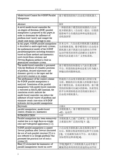
Model-based Control for 6-DOF ParallelManipulator基于模型的控制六自由度并联机器人Abstract 摘要A novel model-based controller forsix-degree-of-freedom (DOF) parallel manipulator is proposed in this paper,in order to abatement the influence of platform load variety and compel the steady state errors converge to zero 一种新的基于模型的控制器的六自由度并联机器人(自由度)提出,以便消除影响平台负载的品种和迫使稳态误差收敛到零In this paper, 6-DOF parallel manipulator is described as multi-rigid-body systems, the mathematical model of the 6-DOF parallelmanipulator including dynamics based on Kane method and kinematics used closed-form solutions andNewton-Raphson method is built in generalized coordinate system. 在本文中,六自由度并联机器人被描述为多刚体系统,数学模型的六自由度并联机器人基于凯恩方法包括动力学和运动学使用封闭形式的解决方案和牛顿迭代法是建立在广义坐标系统。
The model-based controller is presented with the feedback of cylinders positions of platform, desired trajectories and dynamics gravity as the input and the servovalve current as its output. 基于模型的控制器是与气缸位置反馈平台,所需的轨迹和动态重力作为输入和输出的伺服阀电流。
Nonlinear H∞ controller design for a DC-to-DC power converter
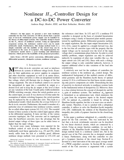
Nonlinearis assumed to haveideal characteristics,that means no losses and zero turn-on andturn-offtimes.with the smooth vectorfieldsin position1to thefixed modulationperiodare continuous[3],[21].Therefore the two systemsof(1)are connected by theconditionsUnder the assumption that the switching frequency is muchhigher than the natural frequencies of the converter system andthe switches are realized with common power semiconductordevices we can derive the so called average model for thePWM controlled converter(1)in theformand the dutyratio(4)andand denotesthe operating point of theˇCuk converter.Then,via a simplechange ofvariablesandand,theˇCuk converter system(3)is linearized and can be written inFig.3.Poles and zeros of the transfer function as a function of the duty ratio. terms of smalldeviationscan be computed asfollows:-plane or in other words the linearized systemshows the typical nonminimum phase behavior of theˇCukconverter.III.P ROBLEM D EFINITION FOR THE C ONTROLLER D ESIGNThe aim of feedback control is to convert the unregulatedinputvoltage into a controlled dc outputvoltage ata desiredlevelto be zero.Furthermore,we also want to have the output voltagetracking any reference trajectory in a prescribed family.It isassumed that the family of reference trajectories is generatedby afinite dimensional autonomous system,the so calledexogenous system.From linear control theory it is a well-known fact thatsimple state-space design will not produce an integral action.Therefore one idea to overcome this restriction is to augmentthe model of the plant with an integrator and design a controllaw for this augmented system.In order to extend this idea tononlinearshows that,if weassume to be bounded,a sufficientlysmallleads to a stationary outputvoltageThe proof of the stability of the closedloop of the augmented system will be given in Section V.Motivated by the fact that for afixed duty ratio an inte-grator with negative gain locally stabilizes theˇCuk converterdescribed by the transfer function(7),the control law is chosenin the followingform:will be designed in such away that the closed-loop systemis(10)where isthe controlinput,are the to-be-controlled outputswithfrom(4)and(5),respectively,weobtainsatisfies theequationsandto the to-be-controlledoutputsifissaid to beinis denoted.Thedenotes the adjoint variable.Following the theory ofdifferential games the Hamiltonian function has in this case a unique global saddle point with thepropertywhereandfromwithsuch that the Hamilton–Jacobiinequalityis a Lyapunov functioncandidate for the closed-loop system [20]andiffrom (11)a positive definite energyfunctioncandidate[12],[8]issatisfies the Hamilton-Jacobiinequalityand by completing the squares weobtainmust hold for theparameterdenotes the maximum allowedoutput voltage.It is apparent that thechoiceisrestricted tosatisfyisalso a Lyapunov function for the closed-loop system(10)withthe control law(16).In order to prove this statement,wecalculateorand this is clearly negative semidefinite,ifanddefined in(22).2)For vanishing exogenous inputs the equilibriumpointwas designed in order to guarantee that the closed-loop systemisand is used to testthe controller performance.The modulation frequency for thePWM actuator is chosen as20kHz and for measurement withthe PC the output low-passfilter cutoff frequency is set at1kHz.The linear control law(24)is realized for an output voltageoperatingpoint(duty ratio of theˇCukconverter),where denotes the unit step.The excellent dis-turbance rejection of the proposed controller is demonstratedin Figs.6and7,respectively.The simulated and measuredtransient responses of the output voltages,when the controlledˇCuk converter is subjected to a loadvariationremains within the possible boundaries.The step responses also show the typical nonminimum phase behavior of theˇCuk converter model.Some additional simulations demonstrate that the proposed controller leads to excellent results even if the dynamic be-havior of theˇCuk converter is changed.For that purpose the capacitorFig.6.Experimental results and simulations in the case of load variations.Fig.7.Experimental results and simulations in the case of input voltage variations.with passive components.Experimental results demonstrate the excellent disturbance rejection and tracking behavior of the proposed controller.One of the key issues for the applicability of nonlinear。
并联整流器环流控制策略研究

并联整流器环流控制策略研究马晨骁;李鸿奎;曾文婷;王启龙【摘要】并联整流器会增加系统的容量以及效率,但是在实际工程中由于电感参数不相等或输出电流不相等都会产生环流,环流会增加输入电流谐波.为了抑制环流,提出一种修正的比例谐振控制器,实现低次零序谐波控制.首先对并联整流器进行详细的建模分析,然后改变零矢量作用时间实现零序环流抑制.此外,为了能够更好地抑制并联整流器的零序环流,在上述基础上,提出一种双采样零序环流抑制方法,以实现整流器并联的最优控制.仿真和试验表明:和现有方法相比,新方法的零序环流抑制能力增强,输出电流波形得到进一步改善.【期刊名称】《电气自动化》【年(卷),期】2018(040)004【总页数】4页(P20-23)【关键词】整流器并联;环流抑制;比例谐振;双采样;零矢量【作者】马晨骁;李鸿奎;曾文婷;王启龙【作者单位】东北电力大学电气工程学院,吉林吉林132012;国网山东省电力公司菏泽供电公司,山东菏泽274000;国网山东省电力公司菏泽供电公司,山东菏泽274000;国网山东省电力公司菏泽供电公司,山东菏泽274000【正文语种】中文【中图分类】TM4640 引言三相PWM变换器广泛应用于低压大电流设备。
随着变换器容量的增加,整流器并联因其具有简单、低成本和高灵活性等优点而得到广泛应用。
然而,当并联整流器的共直流母线和共交流母线时,系统将产生零序环流。
环流会导致输入电流畸变和降低系统的输出性能[1-3]。
因此,零序环流抑制已经成为目前研究的焦点。
文献[4-5]采用隔离变压器的方法实现了并联变换器的零序环流抑制,但是该方法会增加并联系统的体积和成本。
文献[6]提出通过硬件方法实现高频零序环流抑制,但是该方法不能抑制低频零序环流。
为了降低并联系统成本,研究人员提出相关的控制方法,在不增加成本和体积的情况下,实现零序环流的有效抑制。
文献[7]采用SHEPWM调制方法消除三次谐波,实现并联变换器零序环流抑制。
A Unified Control Strategy for Three-Phase Inverter

A Unified Control Strategy for Three-Phase Inverterin Distributed GenerationZeng Liu,Student Member,IEEE,Jinjun Liu,Senior Member,IEEE,and Yalin ZhaoAbstract—This paper presents a unified control strategy that en-ables both islanded and grid-tied operations of three-phase inverter in distributed generation,with no need for switching between two corresponding controllers or critical islanding detection.The pro-posed control strategy composes of an inner inductor current loop, and a novel voltage loop in the synchronous reference frame.The inverter is regulated as a current source just by the inner induc-tor current loop in grid-tied operation,and the voltage controller is automatically activated to regulate the load voltage upon the occurrence of islanding.Furthermore,the waveforms of the grid current in the grid-tied mode and the load voltage in the islanding mode are distorted under nonlinear local load with the conven-tional strategy.And this issue is addressed by proposing a unified load current feedforward in this paper.Additionally,this paper presents the detailed analysis and the parameter design of the control strategy.Finally,the effectiveness of the proposed control strategy is validated by the simulation and experimental results.Index Terms—Distributed generation(DG),islanding,load cur-rent,seamless transfer,three-phase inverter,unified control.I.I NTRODUCTIOND ISTRIBUTED generation(DG)is emerging as a viablealternative when renewable or nonconventional energy resources are available,such as wind turbines,photovoltaic ar-rays,fuel cells,microturbines[1],[3].Most of these resources are connected to the utility through power electronic interfacing converters,i.e.,three-phase inverter.Moreover,DG is a suitable form to offer high reliable electrical power supply,as it is able to operate either in the grid-tied mode or in the islanded mode[2]. In the grid-tied operation,DG deliveries power to the utility and the local critical load.Upon the occurrence of utility outage, the islanding is formed.Under this circumstance,the DG must be tripped and cease to energize the portion of utility as soon as possible according to IEEE Standard929-2000[4].However, in order to improve the power reliability of some local criticalManuscript received December15,2012;revised March4,2013;accepted April21,2013.Date of current version September18,2013.This work was supported in part by the National Basic Research Program(973Program)of China under Project2009CB219705,and by the State Key Laboratory of Elec-trical Insulation and Power Equipment under Project EIPE09109.This paper was presented in part at the26th IEEE Applied Power Electronics Conference and Exposition,Fort Worth,TX,USA,March6–11,2011.Recommended for publication by Associate Editor D.Xu.The authors are with the State Key Lab of Electrical Insulation and Power Equipment,School of Electrical Engineering,Xi’an Jiaotong Univer-sity,Xi’an710049,China(e-mail:zeng.liu@;jjliu@; yobdc54@).Color versions of one or more of thefigures in this paper are available online at .Digital Object Identifier10.1109/TPEL.2013.2262078load,the DG should disconnect to the utility and continue to feed the local critical load[5].The load voltage is key issue of these two operation modes,because it isfixed by the utility in the grid-tied operation,and formed by the DG in the islanded mode,respectively.Therefore,upon the happening of islanding, DG must take over the load voltage as soon as possible,in order to reduce the transient in the load voltage.And this issue brings a challenge for the operation of DG.Droop-based control is used widely for the power sharing of parallel inverters[11],[12],which is called as voltage mode control in this paper,and it can also be applied to DG to real-ize the power sharing between DG and utility in the grid-tied mode[13]–[16],[53].In this situation,the inverter is always regulated as a voltage source by the voltage loop,and the qual-ity of the load voltage can be guaranteed during the transition of operation modes.However,the limitation of this approach is that the dynamic performance is poor,because the bandwidth of the external power loop,realizing droop control,is much lower than the voltage loop.Moreover,the grid current is not controlled directly,and the issue of the inrush grid current dur-ing the transition from the islanded mode to the grid-tied mode always exists,even though phase-locked loop(PLL)and the virtual inductance are adopted[15].The hybrid voltage and current mode control is a popular alternative for DG,in which two distinct sets of controllers are employed[17]–[40].The inverter is controlled as a current source by one sets of a controller in the grid-tied mode,while as a voltage source by the other sets of controller in the islanded mode.As the voltage loop or current loop is just utilized in this approach,a nice dynamic performance can be achieved. Besides,the output current is directly controlled in the grid-tied mode,and the inrush grid current is almost eliminated.In the hybrid voltage and current mode control,there is a need to switch the controller when the operation mode of DG is changed.During the interval from the occurrence of utility outage and switching the controller to voltage mode,the load voltage is neitherfixed by the utility,nor regulated by the DG, and the length of the time interval is determined by the islanding detection process.Therefore,the main issue in this approach is that it makes the quality of the load voltage heavily reliant on the speed and accuracy of the islanding detection method[6]–[10]. Another issue associated with the aforementioned approaches is the waveform quality of the grid current and the load voltage under nonlinear local load.In the grid-tied mode,the output current of DG is generally desired to be pure sinusoidal[18]. When the nonlinear local load is fed,the harmonic component of the load current will fullyflow into the utility.A single-phase DG,which injects harmonic current into the utility for mitigating0885-8993©2013IEEEFig.1.Schematic diagram of the DG based on the proposed control strategy.the harmonic component of the grid current,is presented in[41]. The voltage mode control is enhanced by controlling the DG to emulate a resistance at the harmonic frequency,and then the harmonic currentflowing into utility can be mitigated[42]. In the islanded mode,the nonlinear load may distort the load voltage[43],and many control schemes have been proposed to improve the quality of the load voltage,including a multiloop control method[43]–[46],resonant controllers[48],[49],sliding mode control[47].However,existing control strategies,dealing with the nonlinear local load in DG,mainly focus on either the quality of the grid current in the grid-tied mode or the one of the load voltage in the islanded mode,and improving both of them by a unified control strategy is seldom.This paper proposes a unified control strategy that avoids the aforementioned shortcomings.First,the traditional induc-tor current loop is employed to control the three-phase inverter in DG to act as a current source with a given reference in the synchronous reference frame(SRF).Second,a novel voltage controller is presented to supply reference for the inner induc-tor current loop,where a proportional-plus-integral(PI)com-pensator and a proportional(P)compensator are employed in D-axis and Q-axis,respectively.In the grid-tied operation,the load voltage is dominated by the utility,and the voltage com-pensator in D-axis is saturated,while the output of the voltage compensator in Q-axis is forced to be zero by the PLL.There-fore,the reference of the inner current loop cannot regulated by the voltage loop,and the DG is controlled as a current source just by the inner current loop.Upon the occurrence of the grid outage,the load voltage is no more determined by the utility, and the voltage controller is automatically activated to regulate the load voltage.These happen naturally,and,thus the proposed control strategy does not need a forced switching between two distinct sets of controllers.Further,there is no need to detect the islanding quickly and accurately,and the islanding detec-tion method is no more critical in this approach.Moreover, the proposed control strategy,benefiting from just utilizing the current and voltage feedback control,endows a better dynamic performance,compared to the voltage mode control.Third,the proposed control strategy is enhanced by introduc-ing a unified load current feedforward,in order to deal with the issue caused by the nonlinear local load,and this scheme is implemented by adding the load current into the reference of the inner current loop.In the grid-tied mode,the DG injects harmonic current into the grid for compensating the harmonic component of the grid current,and thus,the harmonic compo-nent of the grid current will be mitigated.Moreover,the benefit of the proposed load current feedforward can be extended into the islanded operation mode,due to the improved quality of the load voltage.The rest of this paper is arranged as follows.Section II de-scribes the proposed unified control strategy for three-phase inverter in DG,including the power stage of DG,the basic idea, and the control diagram.The detailed operation principle of DG with the proposed control strategy is illustrated in Section III. The parameter design and small signal analysis of the proposed control system are given in Section IV.Section V investigates the proposed control strategy by simulation and experimental results.Finally,the concluding remarks are given in Section VI.II.P ROPOSED C ONTROL S TRATEGYA.Power StageThis paper presents a unified control strategy for a three-phase inverter in DG to operate in both islanded and grid-tied modes.The schematic diagram of the DG based on the proposed control strategy is shown by Fig.1.The DG is equipped with a three-phase interface inverter terminated with a LCfilter.The primary energy is converted to the electrical energy,which is then converted to dc by the front-end power converter,and the output dc voltage is regulated by it.Therefore,they can be represented by the dc voltage source V dc in Fig.1.In the ac side of inverter,the local critical load is connected directly.It should be noted that there are two switches,denoted by S u and S i,respectively,in Fig.1,and their functions are different. The inverter transfer switch S i is controlled by the DG,and the utility protection switch S u is governed by the utility.When the utility is normal,both switches S i and S u are ON,and the DG in the grid-tied mode injects power to the utility.When the utility is in fault,the switch S u is tripped by the utility instantly,and then the islanding is formed.After the islanding has been confirmed by the DG with the islanding detection scheme[6]–[10],the switch S i is disconnected,and the DG is transferred from the grid-tied mode to the islanded mode.When the utility is restored, the DG should be resynchronized with the utilityfirst,and then the switch S i is turned ON to connect the DG with the grid.Fig.2.Overall block diagram of the proposed unified control strategy.B.Basic IdeaWith the hybrid voltage and current mode control[17]–[40], the inverter is controlled as a current source to generate the reference power P DG+j Q DG in the grid-tied mode.And its output power P DG+j Q DG should be the sum of the power injected to the grid P g+j Q g and the load demand P load+ j Q load,which can be expressed as follows by assuming that the load is represented as a parallel RLC circuit:P load=32·V2mR(1)Q load=32·V2m·1ωL−ωC.(2)In(1)and(2),V m andωrepresent the amplitude and fre-quency of the load voltage,respectively.When the nonlinear local load is fed,it can still be equivalent to the parallel RLC circuit by just taking account of the fundamental component. During the time interval from the instant of islanding happen-ing to the moment of switching the control system to voltage mode control,the load voltage is neitherfixed by the utility nor regulated by the inverter,so the load voltage may drift from the normal range[6].And this phenomenon can be explained as below by the power relationship.During this time interval, the inverter is still controlled as a current source,and its output power is kept almost unchanged.However,the power injected to utility decreases to zero rapidly,and then the power consumed by the load will be imposed to the output power of DG.If both active power P g and reactive power Q g injected into the grid are positive in the grid-tied mode,then P load and Q load will increase after the islanding happens,and the amplitude and frequency of the load voltage will rise and drop,respectively,according to (1)and(2).With the previous analysis,if the output power of inverter P DG+j Q DG could be regulated to match the load demand by changing the current reference before the islanding is confirmed, the load voltage excursion will be mitigated.And this basic idea is utilized in this paper.In the proposed control strategy,the output power of the inverter is always controlled by regulating the three-phase inductor current i Labc,while the magnitude and frequency of the load voltage v C abc are monitored.When the islanding happens,the magnitude and frequency of the load volt-age may drift from the normal range,and then they are controlled to recover to the normal range automatically by regulating the output power of the inverter.C.Control SchemeFig.2describes the overall block diagram for the proposed unified control strategy,where the inductor current i Labc,the utility voltage v gabc,the load voltage v C abc,and the load current i LLabc are sensed.And the three-phase inverter is controlled in the SRF,in which,three phase variable will be represented by dc quantity.The control diagram is mainly composed by the inductor current loop,the PLL,and the current reference generation module.In the inductor current loop,the PI compensator is employed in both D-and Q-axes,and a decoupling of the cross coupling denoted byω0L f/k PW M is implemented in order to mitigate the couplings due to the inductor.The output of the inner current loop d dq ,together with the decoupling of the capacitor voltage denoted by1/k PW M,sets the reference for the standard space vector modulation that controls the switches of the three-phase inverter.It should be noted that k PW M denotes the voltage gain of the inverter,which equals to half of the dc voltage in this paper.Fig.3.Block diagram of the current reference generation module.The PLL in the proposed control strategy is based on the SRF PLL[50],[51],which is widely used in the three-phase power converter to estimate the utility frequency and phase. Furthermore,a limiter is inserted between the PI compensator G PLL and the integrator,in order to hold the frequency of the load voltage within the normal range in the islanded operation. In Fig.2,it can be found that the inductor current is regulated to follow the current reference i Lref dq,and the phase of the current is synchronized to the grid voltage v gabc.If the current reference is constant,the inverter is just controlled to be a current source,which is the same with the traditional grid-tied inverter. The new part in this paper is the current reference generation module shown in Fig.2,which regulates the current reference to guarantee the power match between the DG and the local load and enables the DG to operate in the islanded mode.Moreover, the unified load current feedforward,to deal with the nonlinear local load,is also implemented in this module.The block diagram of the proposed current reference gen-eration module is shown in Fig.3,which provides the current reference for the inner current loop in both grid-tied and islanded modes.In this module,it can be found that an unsymmetrical structure is used in D-and Q-axes.The PI compensator is adopted in D-axes,while the P compensator is employed in Q-axis.Besides,an extra limiter is added in the D-axis.More-over,the load current feedforward is implemented by adding the load current i LLdq to thefinal inductor current reference i Lref dq. The benefit brought by the unique structure in Fig.3can be rep-resented by two parts:1)seamless transfer capability without critical islanding detection;and2)power quality improvement in both grid-tied and islanded operations.The current referencei Lredq composes of four parts in D-and Q-axes respectively:1)the output of voltage controller i ref dq;2)the grid current reference I gref dq;3)the load current i LLdq;and4)the current flowing through thefilter capacitor C f.In the grid-tied mode,the load voltage v C dq is clamped by the utility.The current reference is irrelevant to the load voltage,due to the saturation of the PI compensator in D-axis,and the output of the P compensator being zero in Q-axis,and thus,the inverter operates as a current source.Upon occurrence of islanding,the voltage controller takes over automatically to control the load voltage by regulating the current reference,and the inverter acts as a voltage source to supply stable voltage to the local load; this relieves the need for switching between different control architectures.Another distinguished function of the current reference gen-eration module is the load current feedforward.The sensed load current is added as a part of the inductor current refer-ence i Lref dq to compensate the harmonic component in the grid current under nonlinear local load.In the islanded mode,the load current feedforward operates still,and the disturbance from the load current,caused by the nonlinear load,can be suppressed by the fast inner inductor current loop,and thus,the quality of the load voltage is improved.The inductor current control in Fig.2was proposed in pre-vious publications for grid-tied operation of DG[18],and the motivation of this paper is to propose a unified control strategy for DG in both grid-tied and islanded modes,which is repre-sented by the current reference generation module in Fig.3. The contribution of this module can be summarized in two as-pects.First,by introducing PI compensator and P compensator in D-axis and Q-axis respectively,the voltage controller is inac-tivated in the grid-tied mode and can be automatically activated upon occurrence of islanding.Therefore,there is no need for switching different controllers or critical islanding detection, and the quality of the load voltage during the transition from the grid-tied mode to the islanded mode can be improved.The second contribution of this module is to present the load current feedforward to deal with the issue caused by the nonlinear local load,with which,not only the waveform of the grid current in grid-tied is improved,but also the quality of the load voltage in the islanded mode is enhanced.Besides,it should be noted that a three-phase unbalanced local load cannot be fed by the DG with the proposed control strategy,because there is noflow path for the zero sequence current of the unbalanced load,and the regulation of the zero sequence current is beyond the scope of the proposed control strategy.III.O PERATION P RINCIPLE OF DGThe operation principle of DG with the proposed unified control strategy will be illustrated in detail in this section,and there are in total four states for the DG,including the grid-tied mode,transition from the grid-tied mode to the islanded mode, the islanded mode,and transition from the islanded mode to the grid-tied mode.A.Grid-Tied ModeWhen the utility is normal,the DG is controlled as a current source to supply given active and reactive power by the inductor current loop,and the active and reactive power can be given by the current reference of D-and Q-axis independently.First, the phase angle of the utility voltage is obtained by the PLL, which consists of a Park transformation expressed by(3),a PIcompensator,a limiter,and an integratorx d x q=23⎛⎜⎜⎜⎝cosθcosθ−23πcosθ+23π−sinθ−sinθ−23π−sinθ+23π⎞⎟⎟⎟⎠×⎛⎝x ax bx c⎞⎠.(3)Second,thefilter inductor current,which has been trans-formed into SRF by the Park transformation,is fed back and compared with the inductor current reference i Lref dq,and the inductor current is regulated to track the reference i Lref dq by the PI compensator G I.The reference of the inductor current loop i Lref dq seems complex and it is explained as below.It is assumed that the utility is stiff,and the three-phase utility voltage can be expressed as⎧⎪⎪⎪⎪⎪⎪⎨⎪⎪⎪⎪⎪⎪⎩v ga=V g cosθ∗v gb=V g cosθ∗−2π3v gc=V g cosθ∗+2π3(4)where V g is the magnitude of the grid voltage,andθ∗is the actual phase angle.By the Park transformation,the utility voltage is transformed into the SRF,which is shown asv gd=V g cos(θ∗−θ)v gq=V g sin(θ∗−θ).(5) v gq is regulated to zero by the PLL,so v gd equals the mag-nitude of the utility voltage V g.As thefilter capacitor voltage equals the utility voltage in the gird-tied mode,v C d equals the magnitude of the utility voltage V g,and v C q equals zero,too. In the D-axis,the inductor current reference i Lref d can be expressed by(6)according to Fig.3i Lref d=I gref d+i LLd−ω0C f·v C q.(6) Thefirst part is the output of the limiter.It is assumed that the given voltage reference V max is larger than the magnitude of the utility voltage v C d in steady state,so the PI compensator, denoted by G V D in the following part,will saturate,and the limiter outputs its upper value I gref d.The second part is the load current of D-axis i LLd,which is determined by the charac-teristic of the local load.The third part is the proportional part −ω0C f·v C q,whereω0is the rated angle frequency,and C f is the capacitance of thefilter capacitor.It isfixed as v C q de-pends on the utility voltage.Consequently,the current reference i Lref d is imposed by the given reference I gref d and the load current i LLd,and is independent of the load voltage.In the Q-axis,the inductor current reference i Lref q consists of four parts asi Lref q=v C q·k Gv q+I gref q+i LLq+ω0C f·v C d(7) where k Gv q is the parameter of the P compensator,denoted by G V Q in the following part.Thefirst part is the output of G V Q,Fig.4.Simplified block diagram of the unified control strategy when DG operates in the grid-tied mode.which is zero as the v C q has been regulated to zero by the PLL.The second part is the given current reference I gref q,and thethird part represents the load current in Q-axis.Thefinal partis the proportional part−ω0C f·v C d,which isfixed since v C d depends on the utility voltage.Therefore,the current referencei Lref q cannot be influenced by the external voltage loop and isdetermined by the given reference I gref q and the load currenti LLq.With the previous analysis,the control diagram of the invertercan be simplified as Fig.4in the grid-tied mode,and the inverteris controlled as a current source by the inductor current loopwith the inductor current reference being determined by thecurrent reference I gref dq and the load current i LLdq.In otherwords,the inductor current tracks the current reference and theload current.If the steady state error is zero,I gref dq representsthe grid current actually,and this will be analyzed in the nextsection.B.Transition From the Grid-Tied Mode to the Islanded Mode When the utility switch S u opens,the islanding happens,and the amplitude and frequency of the load voltage will drift due to the active and reactive power mismatch between the DG and the load demand.The transition,shown in Fig.5,can be divided into two time interval.Thefirst time intervals is from the instant of turning off S u to the instant of turning off S i when islanding is confirmed.The second time interval begins from the instant of turning off inverter switch S i.During thefirst time interval,the utility voltage v gabc is stillthe same with the load voltage v C abc as the switch S i is in ONstate.As the dynamic of the inductor current loop and the voltageloop is much faster than the PLL[52],while the load voltageand current are varying dramatically,the angle frequency of theFig.5.Operation sequence during the transition from the grid-tied mode to the islandedmode.Fig.6.Transient process of the voltage and current when the islanding happens.load voltage can be considered to be not varied.The dynamic process in this time interval can be described by Fig.6,and it is illustrated later.In the grid-tied mode,it is assumed that the DG injects ac-tive and reactive power into the utility,which can be expressed by (8)and (9),and that the local critical load,shown in (10),represented by a series connected RLC circuit with the lagging power factorP g =32·(v C d i gd +v C q i gq )=32v C d i gd (8)Q g =32·(v C q i gd −v C d i gq )=−32v C d i gq(9)Z s load =R s +jωL s +1jωC s=R s +j ωL s −1ωC s=R s +jX s .(10)When islanding happens,i gd will decrease from positive to zero,and i gq will increase from negative to zero.At the same time,the load current will vary in the opposite direction.The load voltage in D -and Q -axes is shown by (11)and (12),and each of them consists of two terms.It can be found that the load voltage in D -axis v C d will increase as both terms increase.However,the trend of the load voltage in Q -axis v C q is uncertain because the first term decreases and the second term increases,and it is not concerned for a whilev C d =i LLd ·R s −i LLq ·X s (11)v C q =i LLq ·R s +i LLd ·X s .(12)With the increase of the load voltage in D -axis v C d ,when it reaches and exceeds V max ,the input of the PI compensator G V D will become negative,so its output will decrease.Then,the output of limiter will not imposed to I gref d any longer,and the current reference i Lref d will drop.With the regulation of the inductor current loop,the load current in D -axis i LLd willdecrease.As a result,the load voltage in D -axis v C d will drop and recover to V max .After i LLd has almost fallen to the normal value,the load voltage in Q -axis v C q will drop according to (12).As v C q is decreased from zero to negative,then the input of the PI compensator G PLL will be negative,and its output will drop.In other words,the angle frequency ωwill be reduced.If it falls to the lower value of the limiter ωmin ,then the angle frequency will be fixed at ωmin .Consequently,at the end of the first time interval,the load voltage in D -axis v C d will be increased to and fixed at V max ,and the angle frequency of the load voltage ωwill drop.If it is higher than the lower value of the limiter ωmin ,the PLL can still operate normally,and the load voltage in Q -axis v C q will be zero.Otherwise,if it is fixed at ωmin ,the load voltage in Q -axis v C q will be negative.As the absolute values of v C d and v C q ,at least the one of v C d ,are raised,the magnitude of the load voltage will increase finally.The variation of the amplitude and frequency in the load volt-age can also be explained by the power relationship mentioned before.When the islanding happens,the local load must ab-sorb the extra power injected to the grid,as the output power of inverter is not changed instantaneously.According to (1),the magnitude of the load voltage V m will rise with the increase of P load .At the same time,the angle frequency ωshould drop,in order to consume more reactive power with (2).Therefore,the result through the power relationship coincides with the previ-ous analysis.The second time interval of the transition begins from the instant when the switch S i is open after the islanding has been confirmed by the islanding detection method.If the switch S i opens,the load voltage v C abc is independent with the grid volt-age v gabc .At the same time,v gabc will reduce to zero theo-retically as the switch S u has opened.Then,the input of the compensator G PLL becomes zero and the angle frequency is invariable and fixed to the value at the end of the first interval.Under this circumstance,v C dq is regulated by the voltage loop,and the inverter is controlled to be a voltage source.With the previous analysis,it can be concluded that the drift of the amplitude and frequency in the load voltage is restricted in the given range when islanding happens.And the inverter is transferred from the current source operation mode to the voltage source operation mode autonomously.In the hybrid voltage and current mode control [17]–[40],the time delay of islanding detection is critical to the drift of the frequency and magnitude in the load voltage,because the drift is worse with the increase of the delay time.However,this phenomenon is avoided in the proposed control strategy.C.Islanded ModeIn the islanded mode,switching S i and S u are both in OFF state.The PLL cannot track the utility voltage normally,and the angle frequency is fixed.In this situation,the DG is controlled as a voltage source,because voltage compensator G V D and G V Q can regulate the load voltage v C dq .The voltage references in D -and Q -axis are V max and zero,respectively.And the magnitude of the load voltage equals to V max approximately,which will。
LLC Series Resonant converters
School of Electrical Engineering and Computer Science Kyungpook National University Taegu, Korea
智能车辆导航控制技术
第34卷 第4期吉林大学学报(工学版) Vol.34 No.4 2004年10月Journal of Jilin University(Engineering and Technology Edition) Oct.2004文章编号:1671-5497(2004)04-0582-05智能车辆导航控制技术马 雷1,王荣本2(1.南京航空航天大学机电学院,江苏南京 210016;2.吉林大学交通学院,吉林长春 130022)摘 要:首先建立了车辆预瞄运动学方程,并通过系统辨识实验得到了转向系统动态方程,然后获得了完整的基于预瞄运动学模型的转向控制模型。
采用滑模变结构控制方法设计了车辆的导航控制器。
针对在设计和实验中遇到的一些问题(前轮转角对控制器输出的影响、实验中系统存在静偏差的原因、预瞄点处的侧向偏差与车辆实际侧向偏差之间的关系等)通过仿真进行了系统的分析,并提出在软件中消除净偏差的解决方法。
最后现场实验验证了导航控制方法满足车辆导航的要求。
关键词:自动控制技术;变结构控制;智能车辆;系统辨识中图分类号:TP242.62 文献标识码:AIntelligent vehicle steering controlMA Lei1,WAN G Rongben2(1.College of Mechanical and Elect rical Engineering,N anjing U niversity of Aeronautics and Ast ronautics,N anjing 210016,China;2.College of T ransportation,Jilin U niversity,Changchun130022,China)Abstract:A preview kinematic equation of vehicle was established at first,and a dynamic equation for vehicle steering system was obtained through system identification experiments.Then,a more integrated steering control model was established based on the preview kinematic equation.A steering controller was designed by means of the sliding variable structure control theory.A simulation was performed to analyze systematically the problems met in the system design and experiments such as the effect of the front2wheel steering angle on the controller output,the static deflection found in experiments,and the relation between the preview lateral deflection and vehicle actual lateral deflection,etc.,and a method to eliminate the deflection in the control software was suggested.The steering control system was verified by field test and its favorable track capability has been demonstrated.K ey w ords:automatic control technology;variable structure control;intelligent vehicle;system identification随着智能交通运输系统(ITS)的迅速发展,智能车辆[1~5]已成为此领域的研究热点。
基于离散状态空间模型的LCL滤波并网变换器控制策略_侯朝勇
律,得到系统在同步旋转坐标系下的向量方程
di1dq (t ) j L1i1dq (t ) ucdq (t ) udq (t ) R1i1dq (t ) L1 dt ducdq (t ) (1) i1dq (t )i2 dq (t ) jC0 ucdq (t )C0 dt u (t ) R i (t ) L di2 dq (t ) j L i (t )e (t ) 2 2 dq 2 2 2 dq dq cdq dt
0 引言
随着风力发电、光伏发电、燃料电池发电等新 能源应用的日益增多,作为电力系统能源的一种补 充,新能源的并网发电将会成为未来的发展趋势。 并网变换器作为并网系统的核心部件之一,一般采 用高频脉宽调制(pulse width modulation,PWM), 但会导致大量的高次谐波电流进入电网。在并网运 行时,注入电网的电流谐波是一项重要的指标, IEEE 1547 标 准 要 求 总 谐 波 失 真 (total harmonic distortion,THD)小于 5%,3、5、7、9 次谐波小于 4%,11、13、15 次谐波小于 2%,17-23 次谐波小 于 1.5%,23-35 次谐波小于 0.6%,35 次以上小于 0.3%[1-2]。针对这些要求,为了获得低 THD 的并网 电流, 采用 LCL 滤波器并网的方式是一种有效降低 并网电流高次谐波含量和总电感值的方法, LCL 滤 波器对高频分量呈高阻抗特性,对高频谐波电流可 以起到很大的衰减作用。 但是, 由于 LCL 滤波器存 在由其物理参数决定的谐振频率,会导致谐振频率 处谐波的幅值增大,从而会增加并网电流中高次谐 波的含量,同时由于谐振还会破坏系统的稳定性, 因此必须采取抑制措施。 为了抑制谐振,在文献 [3-4] 中提出了采用与