AN2867_应用笔记ST微控制器振荡器电路设计指南
集成电路构成的振荡电路
集成电路构成的振荡电路大全集成电路构成的振荡电路大全在电子线路中,脉冲振荡器产生的CP脉冲是作为标准信号和控制信号来使用的,它是一种频率稳定、脉冲宽度和幅度有一定要求的脉冲。
这种振荡器电路不需要外界的触发而能自动产生脉冲波,因此被称为自激振荡器。
一个脉冲波系列是和这个脉冲的基本频率相同的正炫波以及许多和这个脉冲基本频率成整数倍的正炫波谐波合成的,所以脉冲振荡器有时叫做多谐振荡器。
用集成电路构成的振荡器比用分立元件构成的工作要可靠的多,性能稳定。
本电路汇编了用各种集成电路构成的大量振荡器电路。
供读者在使用时参考。
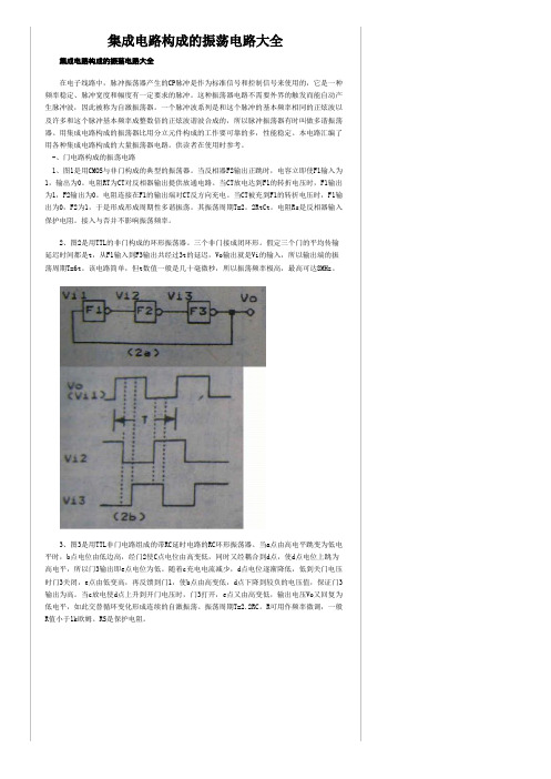
-、门电路构成的振荡电路1、图1是用CMOS与非门构成的典型的振荡器。
当反相器F2输出正跳时,电容立即使F1输入为1,输出为0。
电阻RT为CT对反相器输出提供放通电路。
当CT放电达到F1的转折电压时,F1输出为1,F2输出为0。
电阻连接在F1的输出端对CT反方向充电。
当CT被充到F1的转折电压时,F1输出为0,F2为1,于是形成形成周期性多谐振荡。
其振荡周期T=2。
2RtCt。
电阻Rs是反相器输入保护电阻。
接入与否并不影响振荡频率。
2、图2是用TTL的非门构成的环形振荡器。
三个非门接成闭环形。
假定三个门的平均传输延迟时间都是t,从F1输入到F3输出共经过3t的延迟,Vo输出就是Vi的输入,所以输出端的振荡周期T=6t。
该电路简单,但t数值一般是几十毫微秒,所以振荡频率极高,最高可达8MHz。
3、图3是用TTL非门电路组成的带RC延时电路的RC环形振荡器。
当a点由高电平跳变为低电平时,b点电位由低边高,经门2使C点电位由高变低,同时又经耦合到d点,使d点电位上跳为高电平,所以门3输出即e点电位为低。
随着c充电电流减少,d点电位逐渐降低,低到关门电压时门3关闭,e点由低变高,再反馈到门1,使b点由高变低,d点下降到较负的电压值,保证门3输出为高。
当c放电使d点上升到开门电压时,门3打开,e点又由高变低,输出电压Vo又回复为低电平,如此交替循环变化形成连续的自激振荡。
通信电子电路正弦波振荡器分析课件

RC振荡器自由振荡频率 计算公式
f = 1/(2πRCБайду номын сангаас,其中R为电阻 值,C为电容值。
LC振荡器自由振荡频率计 算公式
f = 1/(2π√(LC)),其中L为电 感值,C为电容值。
THANKS FOR WATCHING
感谢您的观看
01
LC振荡器特点
02
1. 输出频率高,适用于高频应用;
2. 输出波形质量好;
03
设计实例:LC振荡器
1
3. 需要高品质因数的元件,成本较高。
LC振荡器设计要点
2
3
1. 选择合适的电感、电容和放大器;
设计实例:LC振荡器
2. 调整反馈系数和负载电阻;
3. 考虑元件参数的误差和温度稳定性 。
05 正弦波振荡器在通信电子 电路中的应用
设计实例:RC振荡器
RC振荡器特点 1. 电路简单,易于实现;
2. 输出频率稳定,适用于低频应用;
设计实例:RC振荡器
3. 输出波形质量较差。 RC振荡器设计要点 1. 选择合适的电阻、电容和放大器;
设计实例:RC振荡器
2. 调整反馈系数和负载电阻;
3. 考虑元件参数的误差和温度稳定性。
设计实例:LC振荡器
调试方法:如何调试一个RC振荡器
确定元件参数
首先需要确定电阻R和电容C的值 ,以确保振荡器能够产生所需频
率的正弦波。
观察振荡幅度
调整电阻和电容的值,观察振荡 幅度是否达到预期值。如果振荡 幅度不足,可以增加电阻或电容
的值来调整。
01
03
02 04
调整频率
如果振荡幅度正常但频率不准确 ,可以通过改变电容C的值来调 整频率。增加电容的值将降低振 荡频率,反之则会增加振荡频率 。
AN2867ST微控制器振荡器电路设计指南
AN2867Application noteOscillator design guide for ST microcontrollers简介:大局部设计人员对振荡器〔Pierce-Gate topology 皮尔斯门构造〕都很生疏,但真的明白它是如何工作的人并不多,更甭提设计一个适宜的振荡器了。
实际上,很多设计人员并未真正关注过振荡器的设计,直到他们觉察振荡器不正常运行了〔通常这时产品已经投产了〕。
这本是不应当发生的。
很多系统、工程工程的拖延就仅仅是由于一个振荡器没有工作在估量的状态上。
振荡器应当在产品设计阶段就得到足够的重视,并且最好是在投产之前。
这样设计人员才可能避开大批产品被退回来返修那噩梦样的场景。
本应用笔记将介绍皮尔斯〔Pierce〕振荡器的根本原理,并为如何设计一个优良的振荡器供给指导。
同时也会说明如何选取不同的外围元件,并就怎样为振荡器设计一个优良的PCB 供给指导。
本文档的最终局部就如何选取适宜的晶体和外围元件供给一个简洁的指导,并列出一些为STM32 和STM8A/S 推举的晶体型号〔HSE 和LSE〕,以便利快速开头一个设计。
1.石英晶体的特性和模型〔Quartz crystal propertiesandmod e l〕石英晶体是一种压电器件,它能够实现电能和机械能的相互转换。
这个转换发生在谐振频率处。
石英晶体的等效模型如下:Figure 1. Quartz crystal modelC 0:代表电极引入的并联电容Lm:〔振荡电感〕代表晶体的振荡量Cm :〔振荡电容〕代表晶体的振荡弹性Rm :〔振荡电阻〕代表电流损耗晶体的阻抗计算式如下:〔假设Rm是可以无视的〕1 / 12图 2 是晶体在频域内的阻抗曲线。
Figure 2.Impedance representation in the frequency domainF s 是晶体在 Z=0 时的串联谐振频率。
它的表达式可以从等式〔1〕中推导出来:F a 是反谐振频率,此时的Z 趋于无穷大。
振荡器

2) 软激励与硬激励
T 1 A 1 T B A
0
3) 幅度稳定条件:
T ( osc ) Vi V iA
Vi A V i
0
0
相位稳定条件: T ( ) 0 OSC
Vi A V i
4. 结论:
1) 正弦振荡器工作原理包括
起振条件: T ( j osc ) 1 平衡条件: T ( j osc ) 1 稳定条件: T ( osc )
q
rq 1 rq
1 Lq C q
Lq Cq
, P 1 Lq C q // C 0 S
S
当ω=ωs时,x=0为串谐,相当于短路; 当ω=ωp时, x=∞为并谐,相当于开路; 当 ω>ωp ,ω<ωs 时, x<0呈容性; 当 ωs <ω<ωp 时, x>0呈感性。
二、晶振电路
1. 并联型晶振电路:晶体JT→L(ωs <ωosc<ωp )
' 即: g L
gi:输入端对应等效电导(e对地)
gi 1 RE 1 re (当 R E re 时 ) g i 1 re
二、三点式LC振荡器
4. 结论:
1) 判断三点式振荡器是否可能振荡:在电路供电正 确前提下, 看是否满足三点式电路的构成原则。
2) 无论是什么形式的三点式振荡器——振幅的起振 条件均应满足:
c) 是否产生正弦波——看是否有正弦选频网络
§3-3、LC正弦振荡器
一、变压器耦合LC正弦振荡器
1. 单管变压器耦合电路
1) 电路
2) 工作原理
3) 结论
a) 是否可能振荡,取决于变压器正确的同名端标向 b) 是否能起振,取决于变压器是否有足够的耦合量M, c) 正反馈系数 k fV
ST AN2784 应用笔记
AN2784应用笔记使用大容量STM32F10xxx的FSMC驱动外部的存储器前言这个应用笔记说明了如何使用大容量的STM32F10xxx的FSMC(灵活的静态存储器控制器)驱动一组外部的存储器。
文中首先简要地介绍了STM32F10xxx的FSMC控制器,然后给出了包含典型的FSMC配置的存储器接口实例,以及时序计算和硬件连接方法。
本应用笔记的实例是基于STM3210E-EVAL评估版上的存储器,这是大容量STM32F10xxx的评估版。
使用的存储器是一个16位的异步NOR闪存存储器,一个8位的NAND闪存存储器和一个16位的异步SRAM存储器。
文中实例用到的固件库函数和不同存储器的驱动程序,可以在STMicroelectronics的网站上下载:/mcu。
译注:STM3210E-EVAL评估板演示程序说明文档下载地址:/stonline/products/literature/um/14703.pdfSTM3210E-EVAL评估板演示程序包下载地址:/stonline/products/support/micro/files/um0549.zipSTM3210E-EVAL评估板线路图下载地址:/stonline/products/support/micro/files/um0488.zip本译文的英文版下载地址为:/stonline/products/literature/anp/14779.pdf目录使用大容量STM32F10xxx的FSMC驱动外部的存储器目录1STM32F10xxx灵活的静态存储器控制器简介32与非总线复用模式的异步16位NOR闪存接口52.1FSMC配置52.1.1与NOR闪存存储器接口的典型应用62.2时序计算72.3硬件连接82.4从外部NOR闪存存储器执行代码93与非总线复用的16位SRAM接口 113.1FSMC配置113.1.1使用FSMC与SRAM存储器接口的典型应用 123.2时序计算123.3硬件连接133.4使用外部SRAM作为数据存储器 14 4与8位的NAND闪存存储器接口 154.1FSMC配置154.1.1使用FSMC与NAND存储器接口的典型应用 164.2时序计算174.3硬件连接184.4错误校验码计算 194.4.1错误校验码(ECC)计算概述 194.4.2错误检测 20 5100脚的STM32F10xxx的FSMC配置 225.1FSMC与NAND存储器接口 225.2FSMC与NOR存储器接口 221 STM32F10xxx灵活的静态存储器控制器简介灵活的静态存储器控制器(FSMC)是内置于大容量STM32F10xxx的外部存储器控制器。
《振荡器的设计》PPT课件

调制频率越低,调频噪声越大。
1. 调频噪声
可
( 2)均方根频偏
整
调 频 噪 声 也 可 以 用 频 偏 直 接 表 示 , 即 采 用 均 方 根 理频
偏 frms 表 示 调 频 噪 声 , 它 是 单 位 带 宽 噪 声 边 带 对 应 的p频pt
偏 均 方 值 。 frms 的 数 值 由 下 式 表 示
振荡器主要技术指标—调频噪声和相位噪声 可
整
在振荡器电路中,由于存在各种 不确定因素的影响,使振荡频率
理
和振荡幅度随机起伏。
ppt
振荡频率的随机起伏称为瞬时频 率稳定度,频率的瞬变将产生调 频噪声、相位噪声和相位抖动。 振荡幅度的随机起伏将引起调幅 噪声。因此,振荡器在没有外加 调制时,输出的频率不仅含振荡
ppt
2.相位噪声
– (1)相位噪声的定义
– (2)相位噪声的表示法 • ①相位脉动谱密度
• ②频率脉动谱密度
• ③单边带相位噪声谱密度
3.频谱纯度
1. 调频噪声
可
( 1) 功 率 表 示
整
理 调 频 噪 声 可 以 用 离 载 频 f0 为 fm 处 的 单 位 频 带 调 频 噪 声 功 率 P n 与 载 波 功 率
图8-1 振荡器输出的频谱
频率f0,在f0附近还包含许多旁频,连续分布在f0两边。如图8-1 所示,纵坐标是功率,f0处是载波功率(振荡器输出功率),f0 两边的是噪声功率,它同时包含调频噪声功率和调幅噪声功率。
振荡器主要技术指标—调频噪声和相位噪声 可
整
1.调频噪声
理
– (1)功率表示 – (2)均方根频偏
1.介质谐振器
可
(1)微波介质谐振器
正弦波振荡器解析

目录第一章设计任务 (8)一. 设计目的 (8)二. 设计要求和步骤 (8)三.方案设计及选择 (8)1.振荡器的选择 (8)2.信号输出波形的仿真选择 (8)第二章单元电路设计与参数计算 (9)一. LC三点式振荡组成原理图 (10)二.起振条件 (12)三.频率稳定度 (13)四. LC振荡模块设计 (14)第三章总原理图及元器件清单 (15)一.总原理图 (15)二. 元件清单 (17)第四章调试步骤 (18)一. 按设计电路安装元器件 (19)二. 测试点选择 (20)三. 调试 (20)四. 实验结果与分析 (20)五. 频率稳定度 (20)第五章供参考选择的元器件 (21)第六章设计心得和体会 (22)第七章参考文献 (23)第一章设计任务一设计目的(1). 熟悉LC正弦波振荡器的工作原理,以及示波器的原理及用法。
(2).掌握LC正弦波振荡器的基本设计方法。
(3). 理解LC正弦波振荡回路并掌握LC振荡器的设计,装载,调试,及其主要性能参数的测试方法和如何选择电路的测试点。
(4). 了解外界因素、元件参数对振荡器工作稳定性及频率稳定度的影响情,以便提高振荡器的性能。
二设计要求和步骤(1). 设计一个LC正弦波频振荡器。
(2). 利用三端式振荡器原理产生正弦波信号,采用的具体电路不限。
要求给出所选电路的优点和缺点并通过测量值进行证明。
也可以进行不同三端式振荡器的性能比较。
(3).了解电路分布参数的影响及如何正确选择电路的静态工作点。
(4).电路的基本原理,LC正弦波振荡器是各种接收机和发射机中一种常见的电路,常用作载波振荡、本振混频振荡等。
其典型形式为“三点式”振荡电路,其电路简单、频率稳定度高,它的工作原理是在正反馈的基础上,将直流电源提供的能量变成正弦交流输出。
(5)选择所需的方案,画出有关的电路原理图。
三方案设计与选择1.振荡器的选择LC振荡器的电路种类比较多,根据不同的反馈方式,又可分为互感反馈振荡器,电感反馈三点式振荡器,电容反馈三点式振荡器,其中互感反馈易于起振,但稳定性差,适用于低频,而电容反馈三点式振荡器稳定性好,输出波形理想,振荡频率可以做得较高。
ST 晶振设计指南

AN2867Application noteOscillator design guidefor ST microcontrollersIntroductionMost designers are familiar with oscillators (Pierce-Gate topology), but few reallyunderstand how they operate, let alone how to properly design an oscillator. In practice,most designers do not even really pay attention to the oscillator design until they realize theoscillator does not operate properly (usually when it is already being produced). This shouldnot happen. Many systems or projects are delayed in their deployment because of a crystalnot working as intended. The oscillator should receive its proper amount of attention duringthe design phase, well before the manufacturing phase. The designer would then avoid thenightmare scenario of products being returned.This application note introduces the Pierce oscillator basics and provides some guidelinesfor a good oscillator design. It also shows how to determine the different externalcomponents and provides guidelines for a good PCB for the oscillator.This document finally contains an easy guideline to select suitable crystals and externalcomponents, and it lists some recommended crystals (HSE and LSE) for STM32™ andSTM8A/S microcontrollers in order to quick start development.April 2010Doc ID 15287 Rev 31/23Contents AN2867Contents1Quartz crystal properties and model . . . . . . . . . . . . . . . . . . . . . . . . . . . . 6 2Oscillator theory . . . . . . . . . . . . . . . . . . . . . . . . . . . . . . . . . . . . . . . . . . . . 8 3Pierce oscillator . . . . . . . . . . . . . . . . . . . . . . . . . . . . . . . . . . . . . . . . . . . . . 94Pierce oscillator design . . . . . . . . . . . . . . . . . . . . . . . . . . . . . . . . . . . . . 104.1Feedback resistor RF . . . . . . . . . . . . . . . . . . . . . . . . . . . . . . . . . . . . . . . . 104.2Load capacitor C L . . . . . . . . . . . . . . . . . . . . . . . . . . . . . . . . . . . . . . . . . . . . . . . . . . . . . . 114.3Gain margin of the oscillator . . . . . . . . . . . . . . . . . . . . . . . . . . . . . . . . . . . 114.4Drive level DL and external resistor RExt calculation . . . . . . . . . . . . . . . . 124.4.1Calculating drive level DL . . . . . . . . . . . . . . . . . . . . . . . . . . . . . . . . . . . 124.4.2Another drive level measurement method . . . . . . . . . . . . . . . . . . . . . . . 134.4.3Calculating external resistor RExt . . . . . . . . . . . . . . . . . . . . . . . . . . . . . 134.5Startup time . . . . . . . . . . . . . . . . . . . . . . . . . . . . . . . . . . . . . . . . . . . . . . . 144.6Crystal pullability . . . . . . . . . . . . . . . . . . . . . . . . . . . . . . . . . . . . . . . . . . . 14 5Easy guideline for the selection of suitable crystaland external components . . . . . . . . . . . . . . . . . . . . . . . . . . . . . . . . . . . . 156Some recommended crystals for STM32™ microcontrollers . . . . . . . 166.1HSE part . . . . . . . . . . . . . . . . . . . . . . . . . . . . . . . . . . . . . . . . . . . . . . . . . . 166.1.1Part numbers of recommended 8 MHz crystals . . . . . . . . . . . . . . . . . . . 166.1.2Part numbers of recommended 8 MHz ceramic resonators . . . . . . . . . 166.1.3Part numbers of recommended 25MHz crystals(Ethernet applications) . . . . . . . . . . . . . . . . . . . . . . . . . . . . . . . . . . . . . . 176.1.4Part numbers of recommended 14.7456MHz crystals (audioapplications) . . . . . . . . . . . . . . . . . . . . . . . . . . . . . . . . . . . . . . . . . . . . . . 176.2LSE part . . . . . . . . . . . . . . . . . . . . . . . . . . . . . . . . . . . . . . . . . . . . . . . . . . 187Some recommended crystals for STM8A/S microcontrollers . . . . . . . 197.1Part numbers of recommended crystal oscillators . . . . . . . . . . . . . . . . . . 197.2Part numbers of recommended ceramic resonators . . . . . . . . . . . . . . . . 19 8Some PCB hints . . . . . . . . . . . . . . . . . . . . . . . . . . . . . . . . . . . . . . . . . . . 20 2/23Doc ID 15287 Rev 3AN2867Contents 9Conclusion . . . . . . . . . . . . . . . . . . . . . . . . . . . . . . . . . . . . . . . . . . . . . . . . 21 10Revision history . . . . . . . . . . . . . . . . . . . . . . . . . . . . . . . . . . . . . . . . . . . 22Doc ID 15287 Rev 33/23List of tables AN2867 List of tablesTable 1.Example of equivalent circuit parameters. . . . . . . . . . . . . . . . . . . . . . . . . . . . . . . . . . . . . . . 7 Table 2.Typical feedback resistor values for given frequencies . . . . . . . . . . . . . . . . . . . . . . . . . . . 10 Table 3.EPSON®. . . . . . . . . . . . . . . . . . . . . . . . . . . . . . . . . . . . . . . . . . . . . . . . . . . . . . . . . . . . . . . 16 Table 4.HOSONIC ELECTRONIC. . . . . . . . . . . . . . . . . . . . . . . . . . . . . . . . . . . . . . . . . . . . . . . . . . 16 Table 5.CTS®. . . . . . . . . . . . . . . . . . . . . . . . . . . . . . . . . . . . . . . . . . . . . . . . . . . . . . . . . . . . . . . . . . 16 Table 6.FOXElectronics®. . . . . . . . . . . . . . . . . . . . . . . . . . . . . . . . . . . . . . . . . . . . . . . . . . . . . . . . . 16 Table 7.Recommendable condition (for consumer). . . . . . . . . . . . . . . . . . . . . . . . . . . . . . . . . . . . . 16 Table 8.Recommendable condition (for CAN bus) . . . . . . . . . . . . . . . . . . . . . . . . . . . . . . . . . . . . . 16 Table 9.HOSONIC ELECTRONIC. . . . . . . . . . . . . . . . . . . . . . . . . . . . . . . . . . . . . . . . . . . . . . . . . . 17 Table 10.FOXElectronics®. . . . . . . . . . . . . . . . . . . . . . . . . . . . . . . . . . . . . . . . . . . . . . . . . . . . . . . . . 17 Table 11.CTS®. . . . . . . . . . . . . . . . . . . . . . . . . . . . . . . . . . . . . . . . . . . . . . . . . . . . . . . . . . . . . . . . . . 17 Table 12.FOXElectronics®. . . . . . . . . . . . . . . . . . . . . . . . . . . . . . . . . . . . . . . . . . . . . . . . . . . . . . . . . 17 Table 13.ABRACON™ . . . . . . . . . . . . . . . . . . . . . . . . . . . . . . . . . . . . . . . . . . . . . . . . . . . . . . . . . . . 17 Table 14.EPSON TOYOCOM . . . . . . . . . . . . . . . . . . . . . . . . . . . . . . . . . . . . . . . . . . . . . . . . . . . . . . 18 Table 15.JFVNY® . . . . . . . . . . . . . . . . . . . . . . . . . . . . . . . . . . . . . . . . . . . . . . . . . . . . . . . . . . . . . . . 18 Table 16.KDS . . . . . . . . . . . . . . . . . . . . . . . . . . . . . . . . . . . . . . . . . . . . . . . . . . . . . . . . . . . . . . . . . . 18 Table 17.KYOCERA . . . . . . . . . . . . . . . . . . . . . . . . . . . . . . . . . . . . . . . . . . . . . . . . . . . . . . . . . . . . . 19 Table 18.Recommendable conditions (for consumer). . . . . . . . . . . . . . . . . . . . . . . . . . . . . . . . . . . . 19 Table 19.Recommendable conditions (for CAN-BUS). . . . . . . . . . . . . . . . . . . . . . . . . . . . . . . . . . . . 19 Table 20.Document revision history . . . . . . . . . . . . . . . . . . . . . . . . . . . . . . . . . . . . . . . . . . . . . . . . . 22 4/23Doc ID 15287 Rev 3AN2867List of figures List of figuresFigure 1.Quartz crystal model. . . . . . . . . . . . . . . . . . . . . . . . . . . . . . . . . . . . . . . . . . . . . . . . . . . . . . . 6 Figure 2.Impedance representation in the frequency domain. . . . . . . . . . . . . . . . . . . . . . . . . . . . . . . 6 Figure 3.Oscillator principle . . . . . . . . . . . . . . . . . . . . . . . . . . . . . . . . . . . . . . . . . . . . . . . . . . . . . . . . 8 Figure 4.Pierce oscillator circuitry. . . . . . . . . . . . . . . . . . . . . . . . . . . . . . . . . . . . . . . . . . . . . . . . . . . . 9 Figure 5.Inverter transfer function. . . . . . . . . . . . . . . . . . . . . . . . . . . . . . . . . . . . . . . . . . . . . . . . . . . 10 Figure 6.Current drive measurement with a current probe. . . . . . . . . . . . . . . . . . . . . . . . . . . . . . . . 12 Figure 7.Recommended layout for an oscillator circuit. . . . . . . . . . . . . . . . . . . . . . . . . . . . . . . . . . . 20Doc ID 15287 Rev 35/236/23Doc ID 15287 Rev 31 Quartz crystal properties and modelA quartz crystal is a piezoelectric device transforming electric energy to mechanical energyand vice versa. The transformation occurs at the resonant frequency. The quartz crystal canbe modeled as follows:C 0: represents the shunt capacitance resulting from the capacitor formed by the electrodesL m : (motional inductance) represents the vibrating mass of the crystalC m : (motional capacitance) represents the elasticity of the crystalR m : (motional resistance) represents the circuit lossesThe impedance of the crystal is given by the following equation (assuming that R m isnegligible): (1)Figure 2 represents the impedance in the frequency domain.F s is the series resonant frequency when the impedance Z = 0. Its expression can bededuced from equation (1) as follows:(2)Z j w ---w 2L m C m 1–C 0C m +()w 2L m C m C 0–---------------------------------------------------------------×=F s 12πL m C m ---------------------------=Doc ID 15287 Rev 37/23F a is the anti-resonant frequency when impedance Z tends to infinity. Using equation (1), it isexpressed as follows:(3)The region delimited by F s and F a is usually called the area of parallel resonance (shadedarea in Figure 2). In this region, the crystal operates in parallel resonance and behaves asan inductance that adds an additional phase equal to 180 ° in the loop. Its frequency F p (orF L : load frequency) has the following expression:(4)From equation (4), it appears that the oscillation frequency of the crystal can be tuned byvarying the load capacitor C L . This is why in their datasheets, crystal manufacturers indicatethe exact C L required to make the crystal oscillate at the nominal frequency.Table 1 gives an example of equivalent crystal circuit component values to have a nominalfrequency of 8 MHz.Using equations (2), (3) and (4) we can determine F s , F a and F p of this crystal:and .If the load capacitance C L at the crystal electrodes is equal to 10 pF , the crystal will oscillateat the following frequency: .To have an oscillation frequency of exactly 8 MHz, C L should be equal to 4.02 pF .Table 1.Example of equivalent circuit parametersEquivalent componentValue R m8 ΩL m14.7 mH C m0.027 pF C 0 5.57 pFF a F s 1C m C 0-------+=F p F s 1C m 2C 0C L +()----------------------------+⎝⎠⎛⎞=F s 7988768 Hz =F a 8008102 Hz =F p 7995695 Hz =Oscillator theory AN28678/23Doc ID 15287 Rev 32 Oscillator theoryAn oscillator consists of an amplifier and a feedback network to provide frequency selection.Figure 3 shows the block diagram of the basic principle.Where:●A(f) is the complex transfer function of the amplifier that provides energy to keep the oscillator oscillating.●B(f) is the complex transfer function of the feedback that sets the oscillator frequency.To oscillate, the following Barkhausen conditions must be fulfilled. The closed-loop gainshould be greater than 1 and the total phase shift of 360 ° is to be provided:and The oscillator needs initial electric energy to start up. Power-up transients and noise cansupply the needed energy. However, the energy level should be high enough to triggeroscillation at the required frequency. Mathematically, this is represented by |,which means that the open-loop gain should be much higher than 1. The time required forthe oscillations to become steady depends on the open-loop gain.Meeting the oscillation conditions is not enough to explain why a crystal oscillator starts to oscillate. Under these conditions, the amplifier is very unstable, any disturbance introducedin this positive feedback loop system makes the amplifier unstable and causes oscillations to start. This may be due to power-on, a disable-to enable sequence, the thermal noise ofthe crystal, etc. It is also important to note that only noise within the range of serial-toparallel frequency can be amplified. This represents but a little amount of energy, which iswhy crystal oscillators are so long to start up.A f ()A f ()e jf αf ()⋅=B f ()B f ()e jf βf ()⋅=A f ()B f ()⋅1≥αf ()βf ()+2π=A f ()B f ()⋅1»AN2867Pierce oscillator Doc ID 15287 Rev 39/233 Pierce oscillatorPierce oscillators are commonly used in applications because of their low consumption, lowcost and stability.Inv: the internal inverter that works as an amplifierQ: crystal quartz or a ceramic resonatorR F : internal feedback resistorR Ext : external resistor to limit the inverter output currentC L1 and C L2: are the two external load capacitorsC s : stray capacitance is the addition of the MCU pin capacitance (OSC_IN and OSC_OUT)and the PCB capacitance: it is a parasitical capacitance.Pierce oscillator design AN2867 4 Pierce oscillator designThis section describes the different parameters and how to determine their values in orderto be more conversant with the Pierce oscillator design.4.1 Feedback resistor R FIn most of the cases in ST microcontrollers, R F is embedded in the oscillator circuitry. Its roleis to make the inverter act as an amplifier. The feedback resistor is connected between V inand V out so as to bias the amplifier at V out = V in and force it to operate in the linear region(shaded area in Figure5). The amplifier amplifies the noise (for example, the thermal noiseof the crystal) within the range of serial to parallel frequency (F a, F a). This noise causes theoscillations to start up. In some cases, if R F is removed after the oscillations have stabilized,the oscillator continues to operate normally.Table2 provides typical values of R F.Table 2.Typical feedback resistor values for given frequenciesFrequency Feedback resistor range32.768 kHz10 to 25 MΩ1 MHz 5 to 10 MΩ10 MHz 1 to 5 MΩ20 MHz470 kΩ to 5 MΩ10/23Doc ID 15287 Rev 3AN2867Pierce oscillator designDoc ID 15287 Rev 311/234.2 Load capacitor C LThe load capacitance is the terminal capacitance of the circuit connected to the crystaloscillator. This value is determined by the external capacitors C L1 and C L2 and the stray capacitance of the printed circuit board and connections (C s ). The C L value is specified by the crystal manufacturer. Mainly, for the frequency to be accurate, the oscillator circuit has to show the same load capacitance to the crystal as the one the crystal was adjusted for. Frequency stability mainly requires that the load capacitance be constant. The external capacitors C L1 and C L2 are used to tune the desired value of C L to reach the value specified by the crystal manufacturer.The following equation gives the expression of C L :Example of C L1 and C L2 calculation:For example if the C L value of the crystal is equal to 15pF and, assuming that C s = 5pF , then:. That is: .4.3 Gain margin of the oscillatorThe gain margin is the key parameter that determines whether the oscillator will start up or not. It has the following expression:, where:●g m is the transconductance of the inverter (in mA/V for the high-frequency part or in µA/V for the low-frequency part: 32 kHz).●g mcrit (g m critical) depends on the crystal parameters.Assuming that C L1 = C L2, and assuming that the crystal sees the same C L on its pads as the value given by the crystal manufacturer, g mcrit is expressed as follows: , where ESR = equivalent series resistorAccording to the Eric Vittoz theory: the impedance of the motional RLC equivalent circuit of a crystal is compensated by the impedance of the amplifier and the two external capacitances.To satisfy this theory, the inverter transconductance (g m ) must have a value g m > g mcrit . In this case, the oscillation condition is reached. A gain margin of 5 can be considered as a minimum to ensure an efficient startup of oscillations.For example, to design the oscillator part of a microcontroller that has a g m value equal to 25mA/V, we choose a quartz crystal (from Fox) that has the following characteristics: frequency = 8 MHz, C 0 = 7 pF , C L = 10 pF , ESR = 80 Ω.. Will this crystal oscillate with this microcontroller?Let us calculate g mcrit :C L C L1C L2×C L1C L2+--------------------------C s+=C L C s –C L1C L2×C L1C L2+--------------------------10 pF ==C L1 C L2=20 pF =gain m in arg g mg mcrit--------------=g mcrit 4ESR ×2πF ()2×C 0C L +()2×=g mcrit 4802π×86×10×()2××712–×101012–×10+()2×0.23 mA V⁄==Pierce oscillator designAN286712/23Doc ID 15287 Rev 3Calculating the gain margin gives:The gain margin is very sufficient to start the oscillation and the “gain margin greater than 5”condition is reached. The crystal will oscillate normally.If an insufficient gain margin is found (gain margin < 5) the oscillation condition is notreached and the crystal will not start up. Y ou should then try to select a crystal with a lower ESR or/and with a lower C L .4.4Drive level DL and external resistor R Ext calculationThe drive level and external resistor value are closely related. They will therefore be addressed in the same section.4.4.1 Calculating drive level DLThe drive level is the power dissipated in the crystal. It has to be limited otherwise the quartz crystal can fail due to excessive mechanical vibration. The maximum drive level is specified by the crystal manufacturer, usually in mW. Exceeding this maximum value may lead to the crystal being damaged.The drive level is given by the following formula: , where:●ESR is the equivalent series resistor (specified by the crystal manufacturer):●I Q is the current flowing through the crystal in RMS. This current can be displayed on an oscilloscope as a sine wave. The current value can be read as the peak-to-peak value (I PP ). When using a current probe (as shown in Figure 6), the voltage scale of an oscilloscope may be converted into 1mA/1mV .Figure 6.Current drive measurement with a current probeSo as described previously, when tuning the current with the potentiometer, the current through the crystal does not exceed I Q max RMS (assuming that the current through the crystal is sinusoidal).Thus I Q max RMS is given by:gain m in arg g m g mcrit --------------250.23-----------107===DL ESR I Q 2×=ESR R m 1C 0C L ------+⎝⎠⎛⎞2×=Crystalai15838To oscilloscopeCurrent probeI Qmax RMS DL max ESR -----------------I Qmax PP 22-----------------------==AN2867Pierce oscillator designDoc ID 15287 Rev 313/23Therefore the current through the crystal (peak-to-peak value read on the oscilloscope) should not exceed a maximum peak-to-peak current (I Qmax PP) equal to:Hence the need for an external resistor (R Ext ) (refer to Section 4.4.3) when I Q exceeds I Qmax PP . The addition of R Ext then becomes mandatory and it is added to ESR in the expression of I Qmax .4.4.2 Another drive level measurement methodThe drive level can be computed as:DL= I²QRMS × ESR, where I QRMS is the RMS AC current.This current can be calculated by measuring the voltage swing at the amplifier input with a low-capacitance oscilloscope probe (no more than 1pF). The amplifier input current is negligible with respect to the current through C L1, so we can assume that the currentthrough the crystal is equal to the current flowing through C L1. Therefore the RMS voltage at this point is related to the RMS current by:, with:● F = crystal frequency●, where: V pp is the voltage peak-to-peak measured at C L1 level●C tot = C L1 + (C s /2) + C probe where:–C L1 is the external load capacitor at the amplifier input –C s is the stray capacitance –C probe is the probe capacitance)Therefore the drive level, DL, is given by: .This DL value must not exceed the drive level specified by the crystal manufacturer.4.4.3Calculating external resistor R ExtThe role of this resistor is to limit the drive level of the crystal. With C L2, it forms a low-pass filter that forces the oscillator to start at the fundamental frequency and not at overtones (prevents the oscillator from vibrating at 3, 5, 7 etc. times the fundamental frequency). If the power dissipated in the crystal is higher than the value specified by the crystal manufacturer, the external resistor R Ext becomes mandatory to avoid overdriving the crystal. If the power dissipated in the selected quartz is less than the drive level specified by the crystal manufacturer, the insertion of R Ext is not recommended and its value is then 0 Ω..An initial estimation of R Ext is obtained by considering the voltage divider formed by R Ext /C L2. Thus, the value of R Ext is equal to the reactance of C L2. Therefore: .Let us put:●oscillation frequency F = 8 MHz ●C L2 = 15 pFThen: I Qmax PP 22DL max ×ESR---------------------------×=I QRMS 2πF V RMS ×C tot ×=V RMS V pp22----------=DL ESR πF ×C tot ×()2×V pp ()2×2------------------------------------------------------------------------------------=R Ext 12πFC 2-----------------=R Ext 1326 Ω=Pierce oscillator design AN286714/23Doc ID 15287 Rev 3The recommended way of optimizing R Ext is to first choose C L1 and C L2 as explained earlier and to connect a potentiometer in the place of R Ext . The potentiometer should be initially set to be approximately equal to the capacitive reactance of C L2. It should then be adjusted as required until an acceptable output and crystal drive level are obtained.Caution:After calculating R Ext it is recommended to recalculate the gain margin (refer to Section 4.3: Gain margin of the oscillator ) to make sure that the addition of R Ext has no effect on the oscillation condition. That is, the value of R Ext has to be added to ESR in the expression of g mcrit and g m >> g mcrit must also remain true:g m >> g mcrit = 4 × (ESR + R Ext ) × (2 × PI × F)² × (C 0 + C L )²Note:If R Ext is too low, there is no power dissipation in the crystal. If R Ext is too high, there is no oscillation: the oscillation condition is not reached.4.5 Startup timeIt is the time that take the oscillations to start and become stable. This time is longer for aquartz than for a ceramic resonator. It depends on the external components: C L1 and C L2. The startup time also depends on the crystal frequency and decreases as the frequency rises. It also depends on the type of crystal used: quartz or ceramic resonator (the startup time for a quartz is very long compared to that of a ceramic resonator). Startup problems are usually due to the gain margin (as explained previously) linked to C L1 and C L2 being too small or too large, or to ESR being too high.The startup times of crystals for frequencies in the MHz range are within the ms range.The startup time of a 32 kHz crystal is within the 1 s to 5 s range.4.6 Crystal pullabilityPullability refers to the change in frequency of a crystal in the area of usual parallelresonance. It is also a measure of its frequency change for a given change in loadcapacitance. A decrease in load capacitance causes an increase in frequency. Conversely, an increase in load capacitance causes a decrease in frequency. Pullability is given by the following formula:Pullability PPM pF ⁄()C m 6×10²C 0C L +()2×--------------------------------------=AN2867Easy guideline for the selection of suitable crystal and external componentsDoc ID 15287 Rev 315/235Easy guideline for the selection of suitable crystal and external componentsThis section gives a recommended procedure to select suitable crystal/external components. The whole procedure is divided into three main steps:Step1: Calculate the gain margin(please refer to Section 4.3: Gain margin of the oscillator )●Choose a crystal and go to the references (chosen crystal + microcontrollerdatasheets)●Calculate the oscillator gain margin and check if it greater than 5:If Gain margin < 5, the crystal is not suitable, choose another with a lower ESR or/and a lower C L . Redo step 1.If Gain margin > 5, go to step 2.Step2: Calculate the external load capacitors(please refer to Section 4.2: Load capacitor CL )Calculate C L1 and C L2 and check if they match the exact capacitor value on market or not:●If you found the exact capacitor value then the oscillator will oscillate at the exact expected frequency. Y ou can proceed to step 3.●If you did not find the exact value and:–frequency accuracy is a key issue for you, you can use a variable capacitor to obtain the exact value. Then you can proceed to step 3.–frequency accuracy is not critical for you, choose the nearest value found on market and go to step 3.Step3: Calculate the drive level and external resistor(please refer to Section 4.4: Drive level DL and external resistor RExt calculation )●Compute DL and check if is greater or lower than DL crystal :–If DL <DL crystal , no need for an external resistor. Congratulations you have found a suitable crystal.–If DL >DL crystal , you should calculate R Ext in order to have: DL < DL crystal . Y ou should then recalculate the gain margin taking R Ext into account.If you find that gain margin > 5, congratulations, you have found a suitable crystal. If not, then this crystal will not work and you have to choose another. Return to step 1 to run the procedure for the new crystal.16/23Doc ID 15287 Rev 36Some recommended crystals for STM32™ microcontrollers6.1 HSE part6.1.1 Part numbers of recommended 8 MHz crystals6.1.2 Part numbers of recommended 8 MHz ceramic resonatorsTable 7 and Table 8 give the references of recommended CERALOCK ® ceramic resonatorfor the STM32™ microcontrollers provided and certified by Murata.Table 3.EPSON ®Part numberESR C L C 0Gain marginPackage MA-406 or MA-505 or MA-506 (8 MHz)80 Ω10 pF5 pF137.4SMDTable 4.HOSONIC ELECTRONICPart numberESR C L C 0Gain marginPackage HC-49S-8 MHz80 Ω10 pF7 pF107Through-holeTable 5.CTS ®Part number ESR C L C 0Gain marginPackage A TS08A 60 Ω20 pF 7 pF 56.9Through-holeA TS08ASM60 Ω20 pF7 pF56.9SMDTable 6.FOXElectronics ®Part number ESR C L C 0Gain marginPackage FOXSLF/080-2080 Ω20 pF 7 pF 43.1Through-holeFOXSDLF/080-2080 Ω20 pF 7 pF 43.1SMD PFXLF/080-2080 Ω20 pF7 pF43.1SMDTable 7.Recommendable condition (for consumer)Part numberC LPackage CSTCE8M00G55-R0Embedded load capacitors C L1 = C L2 = 33 pFSMDTable 8.Recommendable condition (for CAN bus)Part numberC LPackage CSTCE8M00G15C**-R0(1)1.Refer to the datasheet of the resonator for details on the two asterisks.Embedded load capacitors C L1 = C L2 = 33 pFSMDDoc ID 15287 Rev 317/23For other Murata resonators recommended for STM32 microcontrollers, please refer to the following link:http://search.murata.co.jp/Ceramy/ICListAction.do?sKeyHin=STM32&sKeyMak=ST -MICROELECTRONICS&sLang=en&sParam=STM326.1.3 Part numbers of recommended 25MHz crystals(Ethernet applications)6.1.4Part numbers of recommended 14.7456MHz crystals (audio applications)Table 9.HOSONIC ELECTRONICPart number ESR C L C 0Gain marginPackage 6FA25000F10M1140 Ω10pF 7pF 21.91SMD SA25000F10M1140 Ω10pF7pF21.91Through-holeTable 10.FOXElectronics ®Part number ESR C L C 0Gain marginPackage FOXSLF/250F-2030 Ω20 pF 7 pF 11.58Through-holeFOXSDLF/250F-2030 Ω20 pF 7 pF 11.58SMD PFXLF250F-2030 Ω20 pF7 pF11.58SMDTable 11.CTS ®Part number ESR C L C 0Gain marginPackage A TS25A 30 Ω20 pF 7 pF 11.58Through-holeA TS25ASM30 Ω20 pF7 pF11.58SMDTable 12.FOXElectronics ®Part number ESR C L C 0Gain marginPackage FOXSLF/147-2040 Ω20 pF 7 pF 24.97Through-holeFOXSDLF/147-2040 Ω20 pF7 pF24.97SMDTable 13.ABRACON™Part number ESR C L C 0Gain marginPackage ABMM2-14.7456MHz50 Ω18 pF7 pF29.3SMD。
PAM2846 中文详细说明
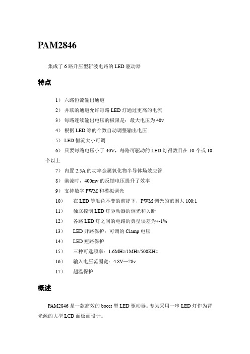
PAM2846集成了6路升压型斩波电路的LED驱动器特点1)六路恒流输出通道2)并联的通道允许每路LED灯通过更高的电流3)每路连续输出电压的极限是:最大电压为40v4)根据LED等的个数自动调整输出电压5)LED恒流大小可调6)只要每路电压小于40V,每路可驱动的LED灯得数目在10个或10个以上7)内置2.5A的功率金属氧化物半导体场效应管8)满流时,400mv的反馈电压提升了效率9)支持数字PWM和模拟调光10)在LED等颜色不变的前提下,PWM调光的范围大100:111)独立控制LED灯驱动器的调光和关断12)各路LED灯之间的电路的典型误差为+-1%13)LED开路保护:可调的Clamp电压14)LED短路保护15)三种可选频率:1.6MHz/1MHz/500KHz16)输入电压范围宽:4.8V—28v17)超温保护概述PAM2846是一款高效的boost型LED驱动器。
专为采用一串LED灯作为背光源的大型LCD面板而设计。
PAM2846采用电流型升压变换器来驱动六支多个串联的并联LED。
这种内置的并联支路电流控制电路能实现各并联之路之间的电流误差的典型值为+-1%,因而能确保每个LED灯得亮度一致。
该芯片能在保持各支路电流恒定的同时还能自适应每条并连支路中LED个数的变化或不同类型LED的不同前向电压。
独立的反馈环在一个或多个LED开路、短路时将限制输出电压。
可以通过改变反馈电阻的值来调整过压保护的下限电压。
PAM2846的输入电压范围宽:4.8V-28V,并且提供可调的LED电流。
主电路应用指南电感的选择选择电感考虑的因素有:电感值、峰值电流值、串联电阻、物理尺寸。
这些因素影响变换器的工作方式、效率、最大输出电压的能力,瞬态响应时间、输出电压纹波和功耗。
电感值由输出电流、输入电压、输出电压和开关频率的最大值决定。
大电感能减少电流纹波,降低峰值电流,这样能降低整个主电路的电感主要损耗和电阻损耗。
在振荡频率点

c b
e
X1
X2
故称为三点式振荡器
X3
三点式振荡器要实现振荡,必须满足相位平衡条件与振幅平衡条件.为此 电路组成结构必须遵循两个原则.
c b
高
频 电
原则一
子
与线 路晶体管
发射极相
联结的电
抗X1、
X2性质必
须相同。
即
be、ce间
电抗性质
e
X1
X2
X3
遵循以上两个原则才能 满足: 相位条件
线 同相,电路满足振荡的相位平衡条件。
路
对 f0 以外的其它频率,L1C 回路处于失谐状态,不 再呈纯电阻性,因而U0 与 Ui 不再是反相关系,自然Uf 与 Ui 也不再是同相关系,也就是说对 f0 以外的电信号,电 路不能满足振荡的相位平衡条件。这样,就保证了振荡电
路只能够输出频率为 f0 的单一频率的正弦波。
高
接成的负反馈,在低频或高频时转化成正反馈,当满足一定
频
条件时就产生了自激振荡。
电
子
线
路
(a) 负反馈放大电路
(b) 正反馈振荡电路
● 输入信号 X i
比较(a)和(b)两图,很容易看出负反馈放大电
● 净输入信号
X
' i
● 输出信号 X o
● 反馈信号 X f
路与正反馈振荡电路的区别。
负反馈时放大器的闭环增益
高
A fu
U 0 U S
U
i
U 0 U
f
1
U 0 U
U
f
f
U
i
1
Au T
频 电 子
当 T <1 时为负反馈放大器
振荡器电路设计注意事项
振荡器电路设计注意事项电路形式的选择实际设计中首先分析振荡器工作的频率,根据其频率值决定选取LC 振荡器或是RC 振荡器或是负阻振荡器或其它形式等。
再者根据对输出频率的稳定度决定采用振荡电路的形式,如clapper 、ciller 、晶体谐振器、温补晶体等等。
具体情况具体对待。
文中对于Rc 振荡器仅仅例举了最常用的文氏桥电路。
RC 振荡器种类很多,总的说来属于反馈振荡器。
利用RC 器件对相位的控制,以及与运放相结合,可以组合出多种形式的振荡器以及输出多种波形。
3 . 2 . 3 . 2 有源器件的选取从原则上讲来,有放大能力的有源器件,以及运放都可以用来组成振荡器。
选择的依据以工作频率为主。
一般说来单管振荡器的振荡频率比运放组成的振荡器工作频率高得多。
当使用单管组成振荡器时,管子的特征频率Ft>(2~10)f0 , f0 是工作频率。
使用运放时,运放的增益带宽积BW 应该大于两倍的工作频率。
当所需输出频率在几KHz 以下时往往采用运放比较合适,输出频率在几MHz 和几十MHz 以上时采用单管振荡器比较合适,当输出频率在几十GHz 时采用负阻振荡器比较合适,此时的振荡回路往往采用微波谐振腔。
3 . 2 .4 振荡器调试时的注意点振荡器调试的主要内容是振荡频率、输出波形、振幅、稳定度等。
它们之间往往相互影响,调试时必须有清晰的振荡器原理,在理论指导下全局考虑。
如:振幅大时输出波形失真也会比较大,当这两个指标互相矛盾时调节方向就应该转移到减小反馈系数或改变反馈网络来解决。
对于工作于高频段的振荡器,在调试时还应该特别注意仪器和环境对振荡回路的影响。
测试仪器的探头输入电容将改变回路特性,影响振荡频率以及反馈系数,必要时可以考虑用串联小电容以及采用高阻探头来解决。
3 . 2 .4 . 1 寄生振荡的产生原因与消除寄生振荡指非符合设计目的而出现的,因电路的寄生参数而形成的正反馈而发生的电路的一种异常振荡状态。
AN2867_ST微控制器振荡器电路设计指南
AN2867_ST微控制器振荡器电路设计指南概述:振荡器电路在数字系统中起着关键作用,它为微控制器提供了时钟信号,使其能够进行计算和控制操作。
在ST微控制器中,振荡器电路的设计非常重要,因为它直接影响到微控制器的整体性能和可靠性。
本文将介绍ST微控制器振荡器电路的设计指南,帮助设计工程师更好地理解和应用。
振荡器电路的类型:在ST微控制器中,可以采用多种不同类型的振荡器电路,例如晶体振荡器、RC振荡器和LC振荡器等。
晶体振荡器是最常见的类型,因为它具有较高的稳定性和精度。
在本文中,我们将重点讨论晶体振荡器电路的设计。
晶体振荡器电路的设计要点:1.晶体振荡器的工作频率应该与微控制器的时钟需求相匹配。
根据具体的应用需求和微控制器的特性,选择适当频率的晶体振荡器。
2.晶体的选取也非常重要。
常见的晶体有石英晶体和陶瓷晶体,其中石英晶体具有更高的精度和稳定性。
根据应用需求和成本考虑,选择适合的晶体。
3.晶体振荡器电路应该具有足够的电源滤波和抗干扰能力。
使用适当的滤波电容和电感,并采取合适的屏蔽措施,以降低电源噪声和外部干扰。
4.晶体振荡器的输出信号应该具有足够的幅值和恢复速度。
为了达到这个目标,可以适当选择放大器的增益和阻尼系数,以及调整负载电容和阻值。
5.对于高频振荡器电路,需要特别注意信号传输线的电磁兼容性(EMC)。
使用合适的线路布局和屏蔽技术,以减少线路之间的互相干扰和噪声。
总结:设计ST微控制器振荡器电路时,需要考虑多个因素,包括工作频率、晶体选择、电源滤波、抗干扰能力和信号恢复速度等。
合理的设计和优化可以提高振荡器电路的性能和可靠性,从而提高整个微控制器系统的性能。
设计工程师应该了解这些设计指南,并根据具体应用需求进行合理的选择和调整。
通过深入理解ST微控制器振荡器电路的设计原理和技术要点,可以更好地应用于实际工程中。
STM32晶振设计指南Oscillator design guide for STM8S,STM8A and STM32 microcontrollers

Oscillator design guide for STM8S, STM8A and STM32 microcontrollers
Introduction
Most designers are familiar with oscillators (Pierce-Gate topology), but few really understand how they operate, let alone how to properly design an oscillator. In practice, most designers do not even really pay attention to the oscillator design until they realize the oscillator does not operate properly (usually when it is already being produced). This should not happen. Many systems or projects are delayed in their deployment because of a crystal not working as intended. The oscillator should receive its proper amount of attention during the design phase, well before the manufacturing phase. The designer would then avoid the nightmare scenario of products being returned. This application note introduces the Pierce oscillator basics and provides some guidelines for a good oscillator design. It also shows how to determine the different external components and provides guidelines for a good PCB for the oscillator. This document finally contains an easy guideline to select suitable crystals and external components, and it lists some recommended crystals (HSE and LSE) for STM32 and STM8A/S microcontrollers in order to quick start development. Refer to Table 1 for the list of applicable products. Table 1. Applicable products
ST AN2857 数据手册
AN2857应用笔记STM8S系列MCU功耗管理介绍本应用笔记面向系统设计人员,提供了STM8S系列产品各种低功耗模式的硬件实现概况;示范了如何在这些低功耗模式下使用STM8S产品;描述了测量功耗和(从低功耗模式)唤醒时间的方法,并给出了测量结果。
本应用笔记提供了测量STM8S不同模式功耗和唤醒时间的固件例程。
译注:本译文的英文版下载地址为:/stonline/products/literature/an/15241.pdf示例程序包下载地址:/stonline/products/support/micro/files/an2857.zip目录1影响功耗的因素 (3)2电源系统 (4)2.1内部电源结构 (4)2.2模拟电源 (4)2.3IO电源 (4)2.4稳压器 (4)3时钟管理 (5)3.1时钟系统概述 (5)3.2时钟设置和功耗管理 (7)4运行模式和低功耗模式 (8)4.1运行模式 (8)4.2等待模式 (8)4.2.1进入等待模式 (9)4.2.2退出等待模式 (9)4.2.3活动等级/低功耗模式控制 (9)4.3活跃停机模式 (9)4.3.1进入活跃停机模式 (10)4.3.2退出活跃停机模式 (10)4.3.3停机阶段的稳压器和闪存设置 (10)4.3.4AWU单元 (11)4.4停机模式 (11)4.4.1进入停机模式 (11)4.4.2退出停机模式 (11)4.4.3在停机模式下闪存设置 (11)5功耗与唤醒事件的测量和结果 (12)5.1功耗测量和结果 (12)5.1.1测量设置 (12)5.1.2运行模式下的功耗测量结果 (14)5.1.3等待模式下的功耗测量结果 (14)5.1.4活跃停机模式下的功耗测量结果 (15)5.1.5停机模式下的功耗测量结果 (15)5.1.6结论 (15)5.2唤醒时间的测量和结果 (16)5.2.1测量设置 (16)5.2.2唤醒时间测量结果 (16)5.2.3等待模式下唤醒时间测量结果 (17)5.2.4活跃停机模式下的唤醒时间测量结果 (17)5.2.5停机模式下的唤醒时间测量结果 (18)5.2.6结论 (18)6功耗管理要点 (19)6.1最小化功耗规则 (19)6.2为应用选择最佳的低功耗模式 (19)1 影响功耗的因素在互补金属氧化物半导体(CMOS)数字逻辑电路中,功耗为下列因子之和:● 静态功耗(主要由晶体管的偏置电流和漏电流产生)● 动态功耗,取决于电源电压和工作时钟频率,按照下面公式:动态功耗 = CV2f,其中─C为CMOS负载电容─V为电源电压─f为时钟频率在CMOS逻辑电路以一定时钟频率运行时,静态功耗与动态功耗相比是可以忽略的。
ST AN2927 应用笔记
7/9
参照2009年2月 AN2927 英文第1版 本译文仅供参考,如有翻译错误,请以英文原稿为准。请读者随时注意在ST网站下载更新版本
AN2867
软件实现
5 当感应I/O引脚上的电压降至VIL: 1. 保存定时器计数器的值(vil_stop),并由此计算降到低电平VIL的时间(vil_stop – vil_start),并保存 2. 将两次测量值“vih_meas”和“vil_meas”相加并保存 3. 重复步骤1的操作
AN2927
应用笔记
用于触摸感应应用的 RC 感应原理
前言
在需要用户界面的应用中,传统的机电开关正在被电容式触摸感应控制做替代。
STMicroelectronics已经开发了一整套的触摸感应软件库,使得任意一款8位的STM8微控制器都 可以作为一个电容式触摸按键控制器使用。欲知更多详情,请访问/mcu。
通过对由一个电阻和触摸电极电容组成的RC网络充放电时间的控制,该触摸感应软件库可以检 测到人手的触摸。由于电极电容的改变,导致的RC网络充放电时间的改变,能够被检测出来, 然后经过滤波等,最终通过专用的I/O端口,或者I2C/SPI接口发送给主机系统。
该软件库所需的元器件BOM表,成本低廉,因为每个通道只需要一个电阻就可以实现触摸检测 功能。
3.4
多次测量以及高频噪声的去除 .............................................................................................8
2/9
参照2009年2月 AN2927 英文第1版 本译文仅供参考,如有翻译错误,请以英文原稿为准。请读者随时注意在ST网站下载更新版本
AN2867_应用笔记ST微控制器振荡器电路设计指南
AN2867应用笔记ST微控制器振荡器电路设计指南前言大多数设计者都熟悉基于Pierce(皮尔斯)栅拓扑结构的振荡器,但很少有人真正了解它是如何工作的,更遑论如何正确的设计。
我们经常看到,在振荡器工作不正常之前,多数人是不愿付出太多精力来关注振荡器的设计的,而此时产品通常已经量产;许多系统或项目因为它们的晶振无法正常工作而被推迟部署或运行。
情况不应该是如此。
在设计阶段,以及产品量产前的阶段,振荡器应该得到适当的关注。
设计者应当避免一场恶梦般的情景:发往外地的产品被大批量地送回来。
本应用指南介绍了Pierce振荡器的基本知识,并提供一些指导作法来帮助用户如何规划一个好的振荡器设计,如何确定不同的外部器件的具体参数以及如何为振荡器设计一个良好的印刷电路板。
在本应用指南的结尾处,有一个简易的晶振及外围器件选型指南,其中为STM32推荐了一些晶振型号(针对HSE及LSE),可以帮助用户快速上手。
目录ST微控制器振荡器电路设计指南目录1石英晶振的特性及模型32振荡器原理53Pierce振荡器64Pierce振荡器设计74.1反馈电阻R F74.2负载电容C L74.3振荡器的增益裕量84.4驱动级别DL外部电阻R Ext计算84.4.1驱动级别DL计算84.4.2另一个驱动级别测量方法94.4.3外部电阻R Ext计算 104.5启动时间104.6晶振的牵引度(Pullability) 10 5挑选晶振及外部器件的简易指南 11 6针对STM32™微控制器的一些推荐晶振 126.1HSE部分126.1.1推荐的8MHz晶振型号 126.1.2推荐的8MHz陶瓷振荡器型号 126.2LSE部分12 7关于PCB的提示 13 8结论141 石英晶振的特性及模型石英晶体是一种可将电能和机械能相互转化的压电器件,能量转变发生在共振频率点上。
它可用如下模型表示:图1石英晶体模型C0:等效电路中与串联臂并接的电容(译注:也叫并电容,静电电容,其值一般仅与晶振的尺寸有关)。
sto电路设计
sto电路设计【原创版】目录1.STM32F103 系列微控制器的简介2.STM32F103 系列微控制器的内部结构3.STM32F103 系列微控制器的引脚功能4.STM32F103 系列微控制器的电路设计流程5.STM32F103 系列微控制器的电路设计注意事项6.总结正文一、STM32F103 系列微控制器的简介STM32F103 系列微控制器是基于 ARM Cortex-M3 内核的 32 位Flash 微控制器,具有高性能、低功耗、多功能、易扩展等特点,广泛应用于各种嵌入式系统中。
二、STM32F103 系列微控制器的内部结构STM32F103 系列微控制器的内部结构主要包括:CPU 内核、内存、外设接口、定时器、中断控制器、电源管理等部分。
这些部分通过内部总线相互连接,构成了一个完整的微控制器系统。
三、STM32F103 系列微控制器的引脚功能STM32F103 系列微控制器的引脚分为 GPIO、高速 GPIO、AF、串行通信、I2C、SPI、CAN 等类型,每种类型的引脚具有不同的功能和特点,可以根据实际需求进行配置和使用。
四、STM32F103 系列微控制器的电路设计流程1.确定微控制器型号和性能参数2.选择外围器件,如存储器、电源、时钟、通信模块等3.设计电路原理图,包括电源电路、时钟电路、通信电路、外围器件接口电路等4.进行电路仿真和测试,验证电路设计是否满足性能要求5.制作电路板,进行硬件调试和测试6.编写程序,对微控制器进行功能测试和优化五、STM32F103 系列微控制器的电路设计注意事项1.电源设计:要考虑电源的稳定性、噪声、纹波等因素,保证微控制器工作在稳定的电源环境下。
2.时钟设计:时钟是微控制器工作的基础,要保证时钟的稳定性和准确性,避免因为时钟问题导致的系统异常。
3.通信接口设计:通信接口是微控制器与其他设备进行数据交换的关键,要考虑通信速率、接口电平、信号完整性等因素。
- 1、下载文档前请自行甄别文档内容的完整性,平台不提供额外的编辑、内容补充、找答案等附加服务。
- 2、"仅部分预览"的文档,不可在线预览部分如存在完整性等问题,可反馈申请退款(可完整预览的文档不适用该条件!)。
- 3、如文档侵犯您的权益,请联系客服反馈,我们会尽快为您处理(人工客服工作时间:9:00-18:30)。
AN2867应用笔记ST微控制器振荡器电路设计指南前言大多数设计者都熟悉基于Pierce(皮尔斯)栅拓扑结构的振荡器,但很少有人真正了解它是如何工作的,更遑论如何正确的设计。
我们经常看到,在振荡器工作不正常之前,多数人是不愿付出太多精力来关注振荡器的设计的,而此时产品通常已经量产;许多系统或项目因为它们的晶振无法正常工作而被推迟部署或运行。
情况不应该是如此。
在设计阶段,以及产品量产前的阶段,振荡器应该得到适当的关注。
设计者应当避免一场恶梦般的情景:发往外地的产品被大批量地送回来。
本应用指南介绍了Pierce振荡器的基本知识,并提供一些指导作法来帮助用户如何规划一个好的振荡器设计,如何确定不同的外部器件的具体参数以及如何为振荡器设计一个良好的印刷电路板。
在本应用指南的结尾处,有一个简易的晶振及外围器件选型指南,其中为STM32推荐了一些晶振型号(针对HSE及LSE),可以帮助用户快速上手。
目录ST微控制器振荡器电路设计指南目录1石英晶振的特性及模型32振荡器原理53Pierce振荡器64Pierce振荡器设计74.1反馈电阻R F74.2负载电容C L74.3振荡器的增益裕量84.4驱动级别DL外部电阻R Ext计算84.4.1驱动级别DL计算84.4.2另一个驱动级别测量方法94.4.3外部电阻R Ext计算 104.5启动时间104.6晶振的牵引度(Pullability) 10 5挑选晶振及外部器件的简易指南 11 6针对STM32™微控制器的一些推荐晶振 126.1HSE部分126.1.1推荐的8MHz晶振型号 126.1.2推荐的8MHz陶瓷振荡器型号 126.2LSE部分12 7关于PCB的提示 13 8结论141 石英晶振的特性及模型石英晶体是一种可将电能和机械能相互转化的压电器件,能量转变发生在共振频率点上。
它可用如下模型表示:图1石英晶体模型C0:等效电路中与串联臂并接的电容(译注:也叫并电容,静电电容,其值一般仅与晶振的尺寸有关)。
L m:(动态等效电感)代表晶振机械振动的惯性。
C m:(动态等效电容)代表晶振的弹性。
R m:(动态等效电阻)代表电路的损耗。
晶振的阻抗可表示为以下方程(假设R m可以忽略不计):图2石英晶振的频域电抗特性其中F s的是当电抗Z=0时的串联谐频率(译注:它是L m、C m和R m支路的谐振频率),其表达式如下:F a是当电抗Z趋于无穷大时的并联谐振频率(译注:它是整个等效电路的谐振频率),使用等式(1),其表达式如下:在F s到F a的区域即通常所谓的:“并联谐振区”(图2中的阴影部分),在这一区域晶振工作在并联谐振状态(译注:该区域就是晶振的正常工作区域,F a-F s就是晶振的带宽。
带宽越窄,晶振品质因素越高,振荡频率越稳定)。
在此区域晶振呈电感特性,从而带来了相当于180 °的相移。
其频率F P(或者叫F L:负载频率)表达式如下:从表达式(4),我们知道可以通过调节负载电容C L来微调振荡器的频率,这就是为什么晶振制造商在其产品说明书中会指定外部负载电容C L值的原因。
通过指定外部负载电容C L值,可以使晶振晶体振荡时达到其标称频率。
下表给出了一个例子来说明如何调整外部参数来达到晶振电路的8MHz标称频率:表1等效电路参数实例等效元件数值R m8ΩL m 14.7mHC m 0.027pFC0 5.57pF使用表达式(2)、(3)和(4),我们可以计算出该晶振的F s、F a及F P:F s = 7988768Hz,F a = 8008102Hz如果该晶振的C L为10pF,则其振荡频率为:F P = 7995695Hz。
要使其达到准确的标称振荡频率8MHz,C L应该为4.02pF。
AN2867 振荡器原理2 振荡器原理振荡器由一个放大器和反馈网络组成,反馈网络起到频率选择的作用。
图3通过一个框图来说明振荡器的基本原理。
图3振荡器的基本原理其中:● A(f)是放大器部分,给这个闭环系统提供能量以保持其振荡。
● B(f)是反馈通道,它决定了振荡器的频率。
为了起振,Barkhausen条件必须得到满足。
即闭环增益应大于1,并且总相移为360°。
为了让振荡器工作,要保证|A(f)|.|B(f)| >> 1。
这意味着开环增益应远大于1,到达稳定振荡所需的时间取决于这个开环增益。
然而,仅满足以上条件是不够解释为什么晶体振荡器可以开始振荡。
为了起振,还需要向其提供启动所需的电能。
一般来说,上电的能量瞬变以及噪声可以提供所需的能量。
应当注意到,这个启动能量应该足够多,从而能够保证通过触发使振荡器在所需的频率工作。
实际上,在这种条件下的放大器是非常不稳定的,任何干扰进入这种正反馈闭环系统都会使其不稳定并引发振荡启动。
干扰可能源于上电,器件禁用/使能的操作以及晶振热噪声等...。
同时必须注意到,只有在晶振工作频率范围内的噪声才能被放大,这部分相对于噪声的全部能量来说只是一小部分,这也就是为什么晶体振荡器需要相当长的时间才能启动的原因。
3 Pierce振荡器皮尔斯振荡器有低功耗、低成本及良好的稳定性等特点,因此常见于通常的应用中。
图4皮尔斯振荡器电路Inv:内部反向器,作用等同于放大器。
Q:石英或陶瓷晶振。
R F:内部反馈电阻(译注:它的存在使反相器工作在线性区, 从而使其获得增益,作用等同于放大器)。
R Ext:外部限流电阻。
C L1和C L2:两个外部负载电容。
Cs:由于PCB布线及连接等寄生效应引起的等效杂散电容(OSC_IN和OSC_OUT管脚上)。
4 Pierce振荡器设计在这一节中,将介绍Pierce振荡器各种参数的含义及如何确定这些参数的值,从而使用户熟悉Pierce振荡器的设计。
4.1 反馈电阻R F在大多数情况下,反馈电阻R F是内嵌在振荡器电路内的(至少在ST的MCU中是如此)。
它的作用是通过引入反馈使反向器的功能等同于放大器。
Vin和Vout之间增加的反馈电阻使放大器在Vout = Vin时产生偏置,迫使反向器工作在线性区域(图5中阴影区)。
该放大器放大了晶振的正常工作区域内的在并联谐振区内的噪声(例如晶振的热噪声)(译注:工作在线性区的反向器等同于一个反向放大器),从而引发晶振起振。
在某些情况下,如果在起振后去掉反馈电阻R F,振荡器仍可以继续正常运转。
图5反向器工作示意图R F的典型值于下表中给出。
表2频率及对应的反馈电阻参考值频率反馈电阻范围32.768kHz 10 至 25MΩ1MHz 5 至 10MΩ10MHz 1 至 5MΩ20MHz 470kΩ至 5MΩ4.2 负载电容C L负载电容C L是指连接到晶振上的终端电容。
C L值取决于外部电容器C L1和C L2,刷电路板上的杂散电容(C s)。
C L值由由晶振制造商给出。
保证振荡频率精度,主要取决于振荡电路的负载电容与给定的电容值相同,保证振荡频率稳定度主要取决于负载电容保持不变。
外部电容器C L1和C L2可用来调整CL,使之达到晶振制造商的标定值。
C L的表达式如下:C L1和C L2计算实例:例如,如果C L =15pF,并假定C s = 5pF,则有:即:C L1 = C L2 = 20pF4.3 振荡器的增益裕量增益裕量是最重要的参数,它决定振荡器是否能够正常起振,其表达式如下:其中:● gm是反向器的跨导,其单位是mA/V(对于高频的情况)或者是µA/V(对于低频的情况,例如32kHz)。
● g mcrit (g m critical)的值取决于晶振本身的参数。
假定C L1 = C L2,并假定晶振的C L将与制造商给定的值相同,则g mcrit表达式如下:其中ESR是指晶振的等效串联电阻。
根据Eric Vittoz的理论(译注:具体可参考Eric A. Vittoz et al., "High-Performance CrystalOscillator Circuits: Theory and Application", IEEE Journal of Solid-State Circuits, vol. 23, No. 3, pp. 774-782, Jun. 1988),放大器和两个外部电容的阻抗对晶振的RLC动态等效电路的电抗有补偿作用。
基于这一理论,反向器跨导(gm)必须满足:gm > gmcrit 。
在这种情况下才满足起振的振荡条件。
为保证可靠的起振,增益裕量的最小值一般设为5。
例如,如果设计一个微控制器的振荡器部分,其gm等于25mA/V。
如果所选择的石英晶振(来自FOX公司)的参数如下:频率 = 8MHz,C0 = 7pF,C L = 10pF,ESR = 80 Ω那么该晶体能否与微控制器配合可靠起振?让我们来计算g mcrit:如果据此来计算增益裕量,可得:此增益裕量远大于起振条件即Gain margin>5,晶振将正常起振。
如果不能满足增益裕量起振条件(即增益裕量Gain margin小于5,晶振无法正常起振),应尝试选择一种ESR较低或/和C L较低的晶振。
4.4 驱动级别DL外部电阻R Ext计算这两个参数是相互联系的,这也就是为什么在同一节中描述此二者的原因。
4.4.1 驱动级别DL计算驱动级别描述了晶振的功耗。
晶振的功耗必须限制在某一范围内,否则石英晶体可能会由于过度的机械振动而导致不能正常工作。
通常由晶振制造商给出驱动级别的最大值,单位是毫瓦。
超过这个值时,晶振就会受到损害。
驱动级别由下述表达式给出:其中:● ESR是指晶振的等效串联电阻(其值由晶振制造商给出):● IQ是流过晶振电流的均方根有效值,使用示波器可观测到其波形为正弦波。
电流值可使用峰-峰值(IPP)。
当使用电流探头时(如图6),示波器的量程比例可能需要设置为1mA/1mV。
图6使用电流探头检测晶振驱动电流如先前所描述,当使用限流电位器调整电流值,可使流过晶振的电流不超过I QMAX均方根有效值(假设流过晶振的电流波形为正弦波)。
I QMAX均方根有效值表达式如下:因此,流过晶振的电流IPP不应超过I QMAX PP(使用峰-峰值表示),I QMAX PP表达式如下:这也就是为什么需要外部电阻R Ext的原因(请参考4.4.3节)。
当I Q超过I Qmax PP时,R Ext是必需的,并且R Ext要加入到ESR中去参与计算I Qmax。
4.4.2 另一个驱动级别测量方法驱动级别可以由下式计算得出:其中I QRMS是交流电流的均方根有效值。
这个电流可以通过使用小电容(<1pF)分布的示波器探头在放大器的输入端,测量电压变化得到。
相对于流经C L1的电流,放大器的输入电流可以忽略不计;因此可以假定经过晶振的电流等于流经C L1的电流。