JE1036HSTL2中文资料
UL 1026-中文版

UL 1026前言A.此標準包括目錄範圍內覆蓋UL公司產品后續服務的基本要求, 這些要求是基于成熟的工程原理, 研究, 測試記錄現場試驗及生產安裝問題的認識, 從廠家, 用戶, 檢驗機構其它專業經驗咨詢時所獲取的信息, 如有必要他們可以進一步實驗調查后改正.B.此標準的觀察要求是持續保證生產廠家產品的條件之一.C.按這些要求在檢查或測試產品時, 只要產品符合此標準, 即使發現預料的其它安全損害, 也可視為符合標準.D.產品采用的材料或者其結構形式與此標準中的要求有些區別, 那么可以按照設計要求測試, 如果大部份材料相同, 那么就可以按照標準進行判斷.E.UL在按照目標進行功能演示時, 不能下放廠家或其它任何部門的責任, 標準在制定時, UL的意見和調查研究結果, 已經代表了專業評判標準, UL對任何使用或依賴下標準不負任何責任, UL不會發生任何責任義務損害, 包括由于使用, 解釋或依賴此標準產生的重大損壞.F.按照UL要求進行測試時有一些不可避免的損害, 因此在進行測試時采取足夠的安全措施和足夠的防護工具是必要的.1.範圍1.1.這些要求覆蓋了在普通情況下使用的250V或以下的家用廚具電器(除了1.2里有說明外),包括臨時或永久地在戶外使用的家用廚具電器應符合國際電器條例規定.1.2.這些要求不包括家用電器系列, 電極型, 長柄鍋及電炸鍋, 乳酪機鍋, 面拖油炸機, 爆谷機, 咖啡壺, 電飯鍋, 微波爐, 以及按個人要求制作的電器不包括在此標準內.1.3.以下內容中, 確定是否符合此範圍內的一種裝置的要求(如多士爐和類似的)應通過具體參考此型號要求, 在沒有具體參考資料時,如果采用"符合"條款, 那么條款應為公認符合標準所有型號的要求.1.4.產品包括外形特點, 零件, 系統更新及與此標準要求有區別的產品,而涉及到火險, 電擊, 傷人應該使用適當的附加零件進行測試, 其安全水平的最后結果應保留在標預期的範圍內, 產品外型, 特性, 零件, 材料, 系統與具體要求相衝突, 不能視為符合此標準, 如果考慮提出修改要求, 應采用一致的方法, 開發, 修正, 執行此標準.2.組合件.2.1.除2.2說明外, 此標準中產品組合件應符合組合件的要求, 如產品一般使用標準組合件清單索引A所示.2.2.組合件不需要與具體相符是:a.此標準包括的產品應用中不必涉及到外形或特性.b.由此標準要求代替.2.3.組合件應在認可的設計環境下使用.2.4.結構中的些特殊組合件不全面或限制其性能發揮, 這些組合件只能在限定環境下使用, 例如不超過一定限定溫度下使用且只有在認可的選定環境下限制使用.3.裝置的測量:3.1.指數必須說明, 括號里的指數為解釋或相近信息.4.參考材料4.1.此標準要求的條例或標準的任何要求更新應被解釋為最新的條例和標準.結構5.總則.5.1 如果電器在運行時會產生或在有氣體或其它氣體壓力下運行, 考慮到爆炸事故的可能性, 因此電器不能算合格, 除非電器有足夠強度抵禦爆炸危險.6.框架與外殼.6.1.電器的框架和外殼應該足夠的張度和鋼度抗拒正常使用中可能的濫用, 但不要因電器固有的抵抗強度而減少電器的空間, 產生松動, 零件錯位而導致部分或全部失效或者結構組合時而增加火險, 電擊或傷害的危險.6.2.電器外殼材料應該能夠隨特殊用途, 能夠容納所有電器零件, 除電源線和14.3,14.4中在任意環境下使用時可能會引起火險, 電擊或傷害的裸線元件外, 如果電器要與電源永久聯接時, 電器外殼應提供用于安裝所必需的裝置, 如: 托架, 挂鉤或類似物.6.3.在正常工作狀態中需要加油的電器, 應特別考慮在烹調腔上加一個外殼, 外殼的材料也應適合此目的.6.4.電器外殼采用通風開口或在外殼上安裝永久電源聯接元件的電器,其位置不能讓排氣進入封閉結構的空間, 如活動頂的空間, 壁洞空間或類似空間.6.5.判斷電器外殼性能時應考慮的因素是:a.物理強度.b.抗衝擊強度.c.吸水汽性.d.可燃性.e.防腐蝕性.f.在高溫下抗變形能力, 外殼在正常和非正常情況下使用的承受能力.對于非金屬材料外殼要求可參考<<電氣設備評估>>UL746C的聚合物標準, 金屬外殼零件或外殼應按照<<金屬外殼衝擊測試>>42節進行抗衝擊能力測試.例外情況1. 考慮按UL746C進行濫用和惡劣條件測試時, 電器外殼應按此標準中濫用運作測試的第44節進行判斷.例外情況2. 因加硬化材料要按43.1要求在高溫下連續1000小時老化測試, 所以加熱硬化材料不需要符合UL746C要求..06.6.采用過熱保護的熱塑外殼電器, 如果采用94HB材料, 具有至少60弧抵抗高電流弧光點火, 至少7秒鐘抗熱點火, 及外殼所有零件包括, 肋骨, 煎件或類似零件相距至少1/2" (12.7mm)那么可燃性要求可不一定要符合UL746C.6.7.除非電器外殼如6.5和6.8判斷認為合格, 否則電器外殼的鑄造和鐵片部分厚度不能小于表格6.1所示.6.8.除了考慮6.5中所提及的因素外, 考慮到電器的設計用途, 外殼金屬片也要考慮其尺寸, 形狀, 厚度和特殊應用能力.6.9.為防止發生無意識與導電零件接觸, 電器上的導電零件, 除自動焗燼裸線元件的發光部分以外, 其位置或包起來保護, 絕緣馬達刷帽不要求額外附件.表6.1金屬外殼的最小厚度6.10外殼構造應該讓熔化金屬, 防火物, 或類似物不會落在支撐面上6.11在6.10必須要求中, 外殼底部開口處的上面或下面必須有隔板, 如果開口為:a.在馬達下面時應:1).馬達的結構零件或電器提供類似的隔板.2).馬達在以下缺陷條件下通電時, 馬達這種保護措施是為了防止燃燒絕緣物或熔化物落在電器的支撐面上.i) 開主線圈.ii)打開起動線圈.iii)啟動短路關.iv)永久分開電容器的馬達為短路電容器, 在馬達通電前和回轉輪被堵時進行短路通電.3).采用熱發動機保護器(同時感應溫度和電流的保護裝置)的發動機是防止發動機線圈在最大負荷的內溫度不超過125℃(302ºF).4). 采用的馬達符合阻抗馬達要求.b.在電線下, 除非電線符合電線, 電纜, 伸縮線UL1581參考標準VW-1燃燒測試或者垂直燃燒測試.c.在無蓋開關, 變壓器, 螺線管或類似物下面, 除非馬達零件不會因為著火而引起故障.d.在電場和工廠制造的拼接過載, 過載電流保護裝置.例如: 如圖6.1D線所示, 如果開口不在組合件下面範圍內, 可以不用隔板.圖6.1隔板呎吋與位置A-隔板遮蓋的範圍,如果組合件沒有被遮蓋,則由整個組合件組成和一個組合件未遮蓋部份(被組合件外殼遮蓋的部份)組成.B-投影在水平板上組合件的輪廓C-隔板傾斜線軸軌跡最小範圍,傾斜線總是1)與零件的切線2)與垂直線5度,和3)水平面的定向軌跡是最大的D- 為隔板最小範圍和位置(水平位),範圍包括傾斜線C和隔板水平面軌跡交叉線6.12於6.11中所提及的擋板應是a)金屬,陶瓷,或作為外殼符合6.5可以接受的原料.b)水平的c)位於圖6.1指示的位置,不應小於圖6.1所描述的位置.6.13 如果在圖6.2中說明的探針通過開口插入不能接觸能引起水險或電擊的任何非常絕緣帶電部件,則在外殼中的開口有小於1英吋(25.4mm)的較小呎吋是可以接受的.探針在插入前、後及過程中適用於所有可能連接的位置.6.14如果在外殼內部沒有非絕緣體或用膠膜包裹的電線,則如圖6.3說明的外殼開口最小呎吋為1英吋或更長一點是可以接受的.R表示至開口周圍里邊的距離,X表示至開口平面的距離,T等於外殼的厚度,R等於X 加T,X等於能插入開口圓桿最大直徑的5倍,但不小於6-1/16英吋(154毫米).在測定開口的過程中,任何在容積範圍內的擋板是可以被忽略的,除非它持續橫切容積邊緣.6.15為了恆溫器的調整或類似的行動,如果在外殼上作一個引起用戶註意的任意大小的孔,不能破壞絕緣體或用直徑為1/16英吋(1.6毫米)插通過孔接觸非絕緣體.6.16關於在6.9和6.13-6.15中的要求,在電器的檢查過程中,外殼的任何部份可被忽視(打開或移動)那是受到的保護能防止電擊或傷人的部份.或如果a)外殼用或不用工具打開或拆卸以執行制造商推薦的用戶服務、維修、操作調整.配件連接或其它操作.b)不用工具能打開或拆卸,見6.16.1例外:如果電器標記與54.9一致,外殼的一部分要求用工具打開或拆卸以執行制造商推薦的用戶服務、維修、操作調整、配件連接或其它操作以保持保持其位置.6.16.1關於6.16(b),為确定外殼或外殼的一部份要求使用工具打開或移動,依靠非金屬部件機械穩固的外殼或外殼的一部份,如塑膠挂耳或快速連軸節插人物或插桿應遵照42A節非金屬外殼緊固器測試.例外:完全通過金屬緊固器(如鏍絲或鉚釘)穩固外殼或外殼的一部份到其它外殼部份,則不需經受此測試.6.17任何活動零件, 例如馬達回轉輪, 鏈條, 滑輪, 帶子和齒輪應褢起來或監視以減少對人的傷害.6.18參照6.17要求, 外殼的保護程度取決于總結構和電器的用途, 以下為判斷裸露活動零件能力應考慮的因素.a.外殼強度b.活動零件的銳利程度.c.無意識與導電零件接觸可能性.d.這些零件移動的速度.e.手指, 手臂或衣服被卷入活動零件的可能性.6.19外殼上的門或蓋上應有手柄以確保進入關閉位置6.20為方便更換過蠛保護裝置或當有需要開蓋操作保護裝置, 外殼上的門或蓋應用絞鏈連接.這些門或蓋應有插銷, 配合緊湊或與外殼表面開口有重壘.6.21電器零件無需用特別工具(不是服務人員就難得到的工具)如果是由人工操作, 調節或定期維護的電器.6.22如果試管或燈泡壞了會嗇火險, 那熱偶的燈泡或毛細管應可以保護電器不被破壞.7組裝7.1 如果電器上有開關, 可連接插頭型插座或插頭型連接器安裝要可靠防止因表面摩擦而使零件產生反轉(動).7.2 為防止裝柄開關轉動可采用鎖墊圈.7.3如果導電零件因附重壓而轉動或轉移而減少零件之間空間低于26.1.1.1-26.1.1.4的要求, 那么導電零件應固定在基面上.7.4 防止導電零件轉動或轉移, 導電零件之間的表面不能產生摩擦可使用鎖墊圈.8. 穩定:8.1 電器的穩定性, 不能因正常使用情況電器很容易傾倒.8.2 家用烹調或熱電器可以輕易用手提或搬運(如矮電器, 食品加熱器或類似的)電器裝上至少50盎司(148ml)水, 加熱到115ºF(46ºC)溫度, 放在與水平面15º的傾斜面上, 無論裝上全部的拆分件, 液體或其它材料, 電器應符合設計使用的最大傾斜角傾倒要求, 電器不會產生滑動, 不能因測試而傾倒.9. 防腐蝕保護9.1 如果因未保護零件的故障增加著火或電擊危險的鐵和鋼片應以瓷釉法, 鍍鋅,電鍍或其它的方法以保護.例外: 某些設備中的氧化鋼不會因為金屬暴露在空氣, 水汽或其它氧化而影響使其加快氧化的金屬其厚度和溫度也是考慮因素, 無需保護, 外殼內金屬片表面要求防腐蝕保護. 鑄壓零件不要求防腐蝕保護, 采用保護套的加熱件和直接連接加熱件的終端零件不需防腐蝕保護.9.2 電器里電鍍或其它處理具有老化性質的零件不能在最后壞至電器不能使用的程度.10. 電源聯接10.1 永久性連接電器10.1.1總則10.1.1.1除10.1.1.2中注明外, 電器采用永久電源聯接設計, 應符合國際電器條例ANSI/NFPA No.7-1993要求.10.1.1.2如果采用活動短電線和可連接插頭作為電源聯接的電器, 可以固定在特點空間. 這種特征的電器還應考慮到電器的應用性, 和電器可連接電源插頭應容易拆開.10.1.1.3 電器按設計要求安裝以后, 終端的位置或永久聯接電器與電源隔板的這些聯接應檢查方便.10.1.1.4 聯接電源保護管的終端間隔與電器的聯接不會產生轉動. 10.1.2 電場電線終端.10.1.2.1 永久聯接電源電器應該采用電線終端或當電流量不低于電器電流量, 連接導體的安載流量不少于電器電流的125%時, 負載邊3小時或以上時這時負載將時斷時續.10.1.2.2 為符合這些要求, 電路終端應為電源接頭或當電器安裝時現場聯接控制.10.1.2.3 電線終端應采用焊接接合, 或可以將電線聯接器牢固地壓入合適位置(如用插銷或螺釘穩固)如果向上接合或類似方法使電線固定, 電線終端容納10AWG(5.3mm2)或更小的導體可以采用線綁螺釘固定.10.1.2.4 電線終端應防止轉動或旋轉, 除表面摩擦外, 可以用兩個螺絲,鉚釘或其它類似方法固定.10.1.2.5 電線終端上的線綁螺釘不能小于10號, 除8號螺釘可以使用在14AWG(2.1mm2)或更小導體的終端聯接中, 6號螺釘可以使用在16AWG(13mm2)或更小的控制電路導體中.10.1.2.6 叩入綁線螺釘的終端金屬片不能小于0.050”(1.3mm)除叩擊螺紋線有相同的機械強度可用于小于0.030”(0.8mm)厚度的金屬上. 如果需要螺紋線伸出金屬上可用雙根螺紋線.10.1.2.7 突出接合處或杯形墊圈可保持導體的能力如果其尺寸為10.1.2.1在螺帽或墊圈下的導體不能小于14AWG(2.1 mm2)10.1.2.8 線綁螺釘應穿入金屬中.10.1.2.9 接地電源導體聯接的電器應:a.Edison螺帽型的燈頭或元件容器.b.單柱開關, 或c.單柱自動控制應有一個終端或頭以確認電源電路接地導體. 除在24.2中說明外, 終端或頭到燈頭或元件容器的螺帽殼視為一個整體, 不是聯接到單柱開關或單柱自動控制器.10.1.2.10 接地聯接電路導體的終端應用白色金屬制成或鍍成白色, 使之非常容易與其它終端與辨出來, 或以其它方法使之容易分辨,如在線路圖上標注, 接地電路導體的頭也要用白色或灰色, 使之與其它頭容易分辨.10.1.2.11 除10.1.2.12說明外, 內部的插座盒或電線間隔長度應為6"(152mm)或以上, 如果頭聯接電場與電路外圍.10.1.2.12 如果有跡象顯示, 使用長頭可能導致火險或電擊, 頭的長度可以少于6"(152mm).10.1.2.13 只聯接設備接地導體的絕緣頭的表面, 應用涂上綠色或黃綠相間的斜帶, 其它頭不必如此.10.1.2.14 聯接設備接地導體的六角形, 溝槽形或都是的綁線螺如應為綠色, 聯接這種導體的壓力電線聯接器應標記"G" "GR""GROUNDING"或類似的或標記在加熱電器上的線路圖里, 以便于區分, 綁線螺絲或壓力電線聯接器位置在電器維護時不會被移動.10.1.2.15 只聯接接地設備導體的終端應能確保特殊電器導體的適當尺寸.10.2 線聯接電器10.2.1 總則10.2.1.1線路聯接電器(用伸縮線路聯接電源電路的一種電器)應有一根電源線聯接電源電路或應有容納可拆或電源線的雄針終端,連接線或分拆線的長度按10.1所示.10.2.1.2線路聯接電器的線路電流量和電壓, 配件不能小于電器的標準, 當電器負載續運行3小時或以上時, 聯接插頭電流量不能小于125%電器電流量.10.2.1.3 電器中的可連接伸縮線和在可拆開電源線的型號應按10.2表格所示, 或其特性至少應能適應特定用途.10.2.1.4 當燒烤器使用在焗爐里時, 焗爐應采用可拆式或電源線, 焗爐和燒烤器都應采用無附件可拆式電源線.10.2.1.5 加強絕緣, 如果采用伸縮線長度不能超出電器外1/2"(13mm)如超出此長度, 應采取機械保護, 防止磨損或松脫, 減少拉緊力產生的不利影響.10.2.1.6 電器不能采用A3-2線制, 接地型接頭.10.2.1.7 15-20A電源線連接插頭的電器一般用3線接地型插座, 開合電器采用的電源線可聯接插頭應該可手工操作, 線聯單柱開關,或是極化或接地型螺口燈座燈柱.10.2.1.8 采用線接地型聯接插頭或2線型極化聯接插頭應符合圖10.1,伸縮極化確認應符合表格10.3要求.10.2.1.9 接地電源導體以下因素也要考慮在里面.a.螺口燈座柱的螺絲殼.b.插座接地終端或頭.10.1為接地電源線確認表.10.2.2 緩解拉力10.2.2.1 緩解拉力應防止聯接伸縮電源線上的機械力傳至終端, 絞接處, 或內線上.10.2.2.2 如果使用材料, 壓力板或其它纖維確保拉力緩解裝配, 纖維材料應用別針, 固定螺釘或其它有效方法予以固定.10.2.2.3 應采用一些措施防止聯接伸縮線通過線入口被壓入電器外殼里面, 確認是否符合此要求, 電源線或頭應按照Push-BackRelief40節A進行測試.10.2.2.4 用電線夾綁緊軟皮線,任何表面可以自由從,邊緣,批鋒,以便導致絕緣導電體擦損.10.2.2.5 當測量結果與10.2.2.6相符時, 伸縮線上的壓力緩解結在斷開電源狀態下以35Lbf(156N)拉線, 應能支撐1分鐘, 無錯位.10.2.2.6 電器結構的電線允許特定力量和從不同角度的拉線. 導體的斷開點, 結果顯示電線移動有足夠連接力.10.2.3 終端針10.2.3.1 如果電器采用終端針, 電器把插頭插在針上時或插上后, 不能使導電零件產生無意識的接觸.10.2.3.2 針護套要求如a.直線邊緣放在任何位置,交叉,與連接插頭開口(插頭沒有插在里面)邊接觸時, 不能與通電的終端針接觸.b.插頭與指針在同一條直線, 板上的插頭與未端或與通電指針成直角,當管道插入任何位電器的開口時, 管道(如圖6.2)不能接觸任何通電指針.10.2.3.3 符合10.2.3.2(b)要求的插頭可以隨附電器.10.2.3.4 采用3個以上的針終端, 并覆蓋所有的指針的電器插頭, 終端的空間不能容納一個熨斗插頭或線聯插頭或導體主體, 這些插頭針應適應于特定電器.10.2.3.5 如果電器采用用戶可拆加熱元件, 這些加熱元件應有如下保證:a.安裝可靠安全耐磨和b.加熱針防止被破壞, 縮短, 當在插入或拆出和彼此更換位置時.10.2.3.6 針終端應安全, 嚴格安裝防止摩擦而產生位置更換.10.2.3.7 10.2.3.6的要求主要是提供空間維護, 說明如26.1.1.1表格26.1和26.2里, 針終端之間保持適當空間. 在此要求中, 還要考慮保持鎖住終端的緊密性方法.10.2.3.8 針的尺寸, 中點與中點之間的距離, 包括一般使用插頭的接觸片之間的相應空間, 采用這些針的規格如10.4所示.10.2.3.9 采用兩針終端的電器不能使用可拆三導體或電源線作為接地導體.10.2.4 杯士10.2.4.1 軟皮線在通過牆隔板或密封盒的任一點時,將有一個杯士或相等同的固定,應光滑,圓渾的表面,如果SP-2, SPT-2型或采用其它比HSJ型輕的伸軟皮線, 如果牆或隔板為金屬, 軟皮線可能要承受拉力或移動時, 絕緣的杯士, 特殊用途的電器套管采用的材料應能隔熱, 抗水汽的特性.10.2.4.2 如果線孔是木材,陶瓷,電木粉成份或其它不導電材料構成,套管的表面應光滑, 圓渾相等同的杯士.10.2.4.3 絕緣套管通常可采用陶瓷材料和一些鑄模結構, 但不能采用,木材, 熱模紫膠, 瀝青, 橡膠等材料的單套管. 如果套管厚度不小于3/64"(1.2mm)在一般水汽條件下不會產生不利影響可采用硬化纖維材料.10.2.4.4 單個的軟橡膠, 氯丁橡膠管套可采用在馬達框架上或邊接馬達的容器外殼(除10.2.4.5說明外不能使用在電器其它地方)且:a.套管厚度不能少于3/64"(1.2mm)b.套管位置不能暴露在油, 油脂, 油性氣體或其它對化合物有破壞影響的物質中.10.2.4.5 如果絕緣連接導管伸縮線無型號要求, 10.2.4.4中所提及的套管的任何材料可以使用在電器中任何部位, 安套管洞口邊光滑無毛邊, 鰭或類似物時.10.2.4.6 如果使用的絕緣材料厚度少于1/32"(0.8mm), 能完全填住安裝金屬的孔眼, 絕緣套管里可以采用絕緣金屬墊圈.11. 通電零件.11.1每一個通電零件所采用的材料應適合特殊用途.11.2通電零件可用抗腐蝕合金做成(如不鏽鋼)不能用普通鐵和鋼做成, 除非這些材料經過表面處理及產生抗腐蝕能力, 即使這樣也適用于:a.針終端b.終端零件, 馬達的其它零件, 馬達控制器.c.正常溫度下操作時超過100°C(212°F)的零件.d.鍍膜鐵和鋼件局部的部件要求參照2.1節所示.11.3 帶水槽的電器, 所有的活動零件其位置或要保護起來而不會因為水槽壞了而掉下來, 除非:a.水槽能抗使用液體腐蝕, 和b.水槽不會因老化而破裂.12. 內線12.1 總則12.1.1電器的內線尺寸, 型號應適用于特殊用途, 并考慮以下特性:a.電線可能承受的溫度和電壓.b.暴露在油或油脂中, 和c.可承受的其他環境.12.1.2玻璃纖維, 無機材料或類似材料作為導體絕緣材料無溫度限制.12.1.3電器內部采用的熱塑絕緣電線應為標準的建築電線, 混合電線或適用于特殊用途的電器電線材料.12.2 電線保護12.2.1線路和零件之間的聯接應予以保護或封閉, 除外部聯接的伸縮線外, 或因為電器使用時可能暴露內部聯接, 線路必須是活動的除外, 絕緣的裸導體或帶珠導體不能在外殼外使用.12.2.2穿過電器外殼開口處而露出的內部線路的保護要求如122.1當認為有鍍膜需要的線路應符合6.9-6.13要求. 內部線路在外殼內不會承受壓力或機械損壞可不需要保護.12.2.3如果電器線路的位置可能靠近可燃材料或機械傷害的線路要用彩盔甲電線或在鋼管, 電子金屬管, 金屬保護里, 或其它保護..12.2.4外殼, 零件, 保護管或類似物內的線路其位置或被保護, 而不會因為接觸任何粗糙, 尖銳或活動零件而損壞導體的絕緣體. 12.2.5絕緣電線通過電器外殼內金屬牆洞口時, 應用一根光滑的導管,或電線通過的表面應光滑圓渾, 以防止絕緣體被擦壞. 如12.2.1用伸縮線作內, 外聯接應按照10.2.2.1-10.2.2.6和10.2.4.1-10.2.4.6進行拉力解緩和采用套管, 除非伸縮線的結構可抗拒拉力和移動, 例外10.2.6 絕緣電線可以扎成束穿過電器外殼內金屬牆洞口.12.3 絞接(疊接)12.3.1所有的絞接和聯接機械性能應可靠, 電子件接觸應應適應, 如果由于聯接的破裂或松動可能引火險或火擊時, 在確保可靠機械性能下可進行死聯接.12.3.2如果絞接處與其它金屬零件之間的距離不能永久保持, 那么絞接處也要采用與電線一樣的絕緣.12.3.3絞接處的絕緣由兩層摩擦帶, 兩層熱塑帶或一層摩擦帶在一層橡膠帶上組成, 考慮其絕緣性, 抗熱性, 抗水汽性, 絞接處絕緣材料可由纖維, 熱塑片或其它型號管子構成. 但熱塑帶不能包尖銳邊.12.3.4連接綁線螺絲和內部線路, 應絕對防止與其它任何同樣極化的導電是線接觸, 與任何死區金屬零件接觸. 可使用壓力終端連接器, 焊接接合, 折皺視孔, 氫所有的電線焊接在一塊或其它類似方法達到目的.12.4分開電路.12.4.1 總則12.4.1.1除非絕緣導體提供最高電壓絕緣, 否則電路絕緣導體分開聯接電源應用隔板隔開, 或單獨聯接電源, 除12.4.1.3說明外,電路上的絕緣導體應為單獨的或與其它不同線路導電零件和絕緣零件分開.12.4.1.2絕緣導體的分開可采用夾, 路線, 或類似能與不同電路的絕緣和導電零件永久分開的方法.12.4.1.3 任何電路的現場安裝導體應隔與….分開.a.現場安裝導體和工廠導體與其它任何電路的聯接, 除非兩個電路導體與每個電路最大電壓絕緣. 和b.電器中任何其它電路的導電零件與任何導電零件的短路將會導致火險, 和電擊, 除…1). 電場安裝導體的結構型或為T, TF型時或安裝的相似導體可。
3M QTII 冷凝式三核电缆终端系列数据表说明书

3 QTIICold Shrink Three Core Indoor / Outdoor Terminations94-EB6x-4 Series for 19/33(36) kV CablesApplication3M™ QTII Cold Shrink Series Kits are designed for 36kV Umax voltage class, three core polymeric power cable systems according to HD 620 (IEC60502).Kit Content3M™ 94-EB6x-4 Series Terminations include the Cold Shrink QTII Silicone Termination body with integrated stress control device, and silicone elastomeric insulation. Silicone tape is included for moisture sealing. Scotchcast Resin is included for sealing the cable crutch. Also included are all armour continuity components, re-jacketing tubes, and three core cold shrink breakout boots.Skirts are integrated for faster & easier installation.Product Features• The versatile design of the prefabricated one-piece cold shrink termination body allowsinstallation on a wide range of cable sizes andtypes and a fast and easy installation attemperatures ranging from - 20°C to + 50°C.• No heat or flame is needed during installation.• Solderless earth connection using ConstantForce springs.• No special tools needed during installation.Installation3M™ Cold Shrink technology ensures quick, easy andsafe installation of the QTII Termination Body bypulling and unwinding the plastic support core incounter clockwise direction. Use of special tools is notnecessary.Detailed instructions for installing the 3M™ QTIISeries Terminations are included in each kit.Product Identification3M™ QTII Series Termination kits are marked with supplier name, cable cross section ranges, voltage class and cable type, storage conditions and manufacturing codes for product traceability.Performance Tests3M™ QTII 94-EB6x-4 Series Terminations meet and exceed the requirements of the European standard CENELEC HD 629.1 as well as IEC 60502-4.See Test Report No; TbaStorageThe shelf life of 3M™ QTII Series Terminations is specified as 3 years.Temperature: - 40°C to +50°C.Page 1 of 2Issue 13M and Scotchcast are trademarks of 3M CompanyImportant NoticeAll statements, technical information and recommendations related to the Seller’s products are based on information believed to be reliable, but the accuracy or completeness thereof is not guaranteed. Before utilizing the product, the user should determine the suitability of the product for its intended use. The user assumes all risks and liability whatsoever in connection with such use.Any statements or recommendations of the Seller which are not contained in the Seller’s current publications shall have no force or effect unless contained in an agreement signed by an authorized office of the Seller.The statements contained herein are made in lieu of all warranties, expressed or implied, including but not limited to the implied warranties of merchantability and fitness for a particular purpose which warranties are hereby expressly disclaimed. SELLER SHALL NOT BE LIABLE TO THE USER OR ANY OTHER PERSON UNDER ANY LEGAL THEORY; INCLUDING BUT NOT LIMITED TO NEGLIGENCE OR STRICT LIABILITY; FOR ANY INJURY OR FOR ANY DIRECT; INDIRECT; INCIDENTAL OR CONSEQUENTIAL DAMAGES SUSTAINED OR INCURRED BY REASON OF THE USE OF ANY OF THE SELLER’S PRODUCTS.Electrical Markets Division3M United Kingdom PLC3M Ireland Ltd 3M United Kingdom PLC Sales OfficeSales Office Head Office PO Box 393The Iveagh Building, The Park, 3M Centre, Cain Road Bedford MK41 0YECarrickmines, Dublin 18, Ireland Bracknell, Berkshire RG12 8HT Telephone************Telephone: (01) 800 812 732 Telephone: 01344 858 000 Fax: 01234 229 433 Fax: 353 1 280 3509 Fax: 01344 858 758Page 2 of 2 Issue 1 Product Selection Kit Reference Application Range Guide (mm²) Diameter over primary insulation (mm) Max. Lug diameter accepted (mm) 94-EB63-425 – 150 21.3 – 35.0 35 94-EB64-495 – 240 27.4 – 45.7 45Product Stewardship3M has a fundamental concern for all who make, distribute and use its products, and for theenvironment in which we live. This concern is the basis of our philosophy and policies by which we assess the health and environmental information on our products and then take the appropriate steps to protect employee, the public health and the environment.Customer Notice3M encourages its customers and potential users of 3M products to review their applications for such products from the standpoint of human health and environmental quality. To help ensure that 3M products are not used in ways for which they were not intended or tested. 3M personnel are available to assist customers in dealing with ecological and product safety considerations. Your 3M sales representative can arrange for the proper contacts.Regulatory Status3M™ QTII Series Terminations are not subject of the European WEEE and RoHS Directives but meet their requirements.。
Jencons 产品型号及温度传感器数据表说明书

El mango está moldeado de manera permanente a la vaina de la sonda, incluye cable y conector miniatura* Especifique tipo de unión: E (expuesta), G (a tierra) o U (sin conexión a tierra). Nota: El recubrimiento PFA está disponible, con un mango no moldeado en su lugar. Haga el pedido del número de pieza estándar con el sufijo “-PFA”, con coste adicional. 200 °C máximo. ** Para una clasificación de temperatura y estabilidad más alta, cambie “SS” o “IN” por “XL ”, con coste adicional.Ejemplos de pedido: KHSS-IM30G-RSC-300, vaina de acero inoxidable 304, de tipo K, unión con conexión a tierra de 3,0 mm, de 300 mm de largo.Para longitudes adicionales, consulte al Departamento de Ventas. Para solicitar una vaina de acero inoxidable 310, 316 o 321, cambie “SS” en el número de modelo por “310SS, 316SS o 321SS”; sin coste adicional. KHXL-IM60G-RSC-300, Super OMEGACLAD TM , vaina de acero inoxidable 321, de tipo K, unión con conexión a tierra de 6 mm, de 300 mm de largo.El cable retráctil de 0,3 m se expande a 1,5 mSe muestra en un tamaño inferior al real.U M ango moldeado calificado a 220 °C U E l cable retráctil con memoria superior se expande a 1,5 m U M ini clavija de termopar para utilizar contermómetros manuales U L ongitudes estándar de 300, 450 y 600 mm; longitudes personalizadas disponibles U S onda RTD deacoplamiento, tipo PR-16 (véase la página 94)U V ainas de acero inoxidable304, 310, 316 y 321, Inconel Ny Super OMEGACLADTM XLPROBE TIPS CUTAWA Y ART PROBE TIPS CUTAWA Y ART Sondas de termopar de varilla con mangoDisponibilidad de sondas depunta especial económicas*Las calificaciones de temperatura dependen del tipo de termopar, el diámetro de la vaina y el entorno.Sonda de aireEl elemento expuesto permite el flujo de aire para una medición rápida. Calificada a 870 °C. Disponible con diámetro de 4,5 mm y unión expuesta solamente.Para hacer el pedido, añada el sufijo “-AP ” al número de modelo por un coste adicional.Ejemplo de pedido: KHSS-IM45-RSC-300-AP , sonda con mango de 300 mm de largo , tipo K, DE de 4,5 mm, vaina de acero inoxidable 304, unión expuesta, punta de sonda de aire.Nota: Disponibilidad de otros estilos, consulte Sonda de penetración (muy popular)Punta cónica, para inserción en materiales blandos y semicongelados. Calificada a 1.150 °C. Disponible con diámetro de 4,5 o 6 mm y unión con conexión a tierra solamente.Para hacer el pedido, añada el sufijo “-NP ” al número de modelo por un coste adicional.Ejemplo de pedido: KHSS-IM45-RSC-300-NP , sonda con mango de 300 mm de largo , tipo K, DE de 4,5 mm, vaina de acero inoxidable 304, unión con conexión a tierra, punta de sonda cónica.Nota: Disponibilidad de otros estilos, consulte Cable retráctilEl cable retráctil de 0,3 m se expande a 1,5 m, la clavija de termopar estándar se acopla a todos los termómetros manuales para una conexión práctica.U Large Backlit Display U Built-In IR Pyrometer Protegido por patentes estadounidenses e internacionales y solicitudes pendientes.PATENTADO¡S ond a s de t e r m o p a r c o nU S B i n c o r p or a d o ! C o n s u l t ee s .o m e g a .c o mVisite para obtener más información acerca del SUPERMETER TMMedidor manual recomendadoHHM290Sonda noincluida.。
flukehydraseries2说明书

flukehydraseries2说明书Fluke Hydra Series 2 IntroductionThe Fluke Hydra Series 2 is a highly advanced multi-channel data acquisition system, designed for applications involving multiple instrumentation sources. This system allows users to simultaneously acquire, process, store and display data from multiple sources, while also offering a wide range of features.The Hydra Server offers the highest available data sampling rates, and it supports many different types of data acquisition, including analog, digital, and thermocouple data. It also features a variety of signal conditioning and filtering functions, allowing users to make precise measurements. Additionally, the Hydra Server includes advanced data analysis and display capabilities, including built-in graphing tools and statistical analysis functions.Fluke Hydra Series 2 BenefitsThe Fluke Hydra Series 2 provides a number of unique benefits, including:• High data sampling rates. The Hydra Server is capable of capturing data at rates up to 500k samples per second, making it ideal for high speed data acquisition and analysis applications.• Flexible signal conditioning and filtering. The Hydra Server is equipped with a wide range of signal conditioning and filtering functions, allowing users to make precise measurements.• Intuitive client software. The Hydra Client software provides an intuitive user interface for easy configuration and control of the Hydra Server.Conclusion。
TestXpertII中文操作说明书

Zwick 软件操作说明一启动testXpertII程序二设置机器参数三设置测试参数——向导四 ZWICK万能材料试验机操作步骤(拉伸测试)五安全措施说明六修整七维护保养说明一、启动testXpertII程序1、打开计算机及控制箱上的电源2、双击图标3、单击“打开”将会出现如下图所示,显示所有程序4、双击所选程序5、单击“确定”,进入测试界面打开控制面板上的电源on二、设置机器参数1、单击“试验机”图标,将出现“标准仪器设置”框。
如图所示:上软限位(在程序控制下,横梁所能到达的最高位置,可根据实际情况设定)下软限位(在程序控制下,横梁所能到达的最低位置,可根据实际情况设定)当前工具间距/当前夹具间距(每次更换夹具时,都要将实测的夹具间距离值输入这里)载荷上限(设置载荷的上限位保护,一般为满负荷的120%)载荷下限(设置载荷的下限位保护,一般为满负荷的-120%)标准引伸计(当采用横梁做为位移测量时,选择横梁WN:******,当采用引伸计传感器做为位移测量时,请选择长量程引伸计WN:******)2、点击“扩展”如图所示:2.5N1S WN:170862 (机器编号)和试验机(机器)相连横梁 WN :170862(横梁编号)和横梁相连长量程引伸计(引伸计的名称)和标准引伸计相连当不使用长量程引伸计时,请将标准引伸计和横梁相连,如下图所示力传感器0.5KN(传感器的负荷)和标准传感器相连。
2、在“测试环境”中取一个名称,保存机器设置结果,不同的设置请保存为不同的“测试环境”名。
3、点击“确定”退出。
三、设置测试参数——Wizard(向导)用户所有的测试参数都在“向导”里设定和执行1、进入向导,单击“预测试”,进入如下文本框可根据需要设定文本框中的内容应注意:预载力一般为0.1---2N,预载测试速度一般为10mm/min,可根据实际情况设定。
在参数前口里打x 的为选择所需的测试参数,参数前口里没有打 x的未选。
霍尼韦尔报警系统设备参数(版)教学内容

报警系统设备参数目录目录1.控制主机 (5)1.14110DL控制主机 (5)1.2VISTA-10P控制主机 (6)1.3VISTA-20P控制主机 (7)1.4VISTA-120/250总线制大型控制主机 (9)1.5Vista-128BPT/ Vista-250BPT (11)1.6COMPACT-4 4防区控制主机【GPRS主机】 (12)1.7236 PLUSII控制主机 (13)1.8238C PLUSII控制主机 (14)1.9238C Super 控制主机 (15)1.102316PLUSII控制主机 (18)1.112316super 控制主机 (19)1.12L YNX家居无线控制主机 (21)2.报警模块及附件 (24)2.1报警键盘 (24)2.1.16148CH固定字符键盘 (24)2.1.26160可编程英文液晶键盘 (24)2.1.3236PLUS LED控制键盘 (25)2.1.4238CPLUS LED控制键盘 (25)2.1.52316PLUS LED控制键盘 (26)2.1.62300Alpha Plus II 控制键盘 (26)2.2VISTA系列附件 (27)2.2.14229八防区扩展模块 (27)2.2.24219八防区扩展模块 (27)2.2.34293SN单防区扩展模块 (28)2.2.44193SN双防区扩展模块 (28)2.2.54193SNP双防区扩展模块 (29)2.2.64208SN八防区扩展模块 (29)2.2.74101SN总线继电器模块 (30)2.2.84204 四路继电器联动模块 (30)2.2.94232AP 32路继电器模块 (30)2.2.104286语音模块 (31)2.2.114100SM串行接口模块 (32)2.2.12IP-2000网络接口展模块 (32)2.2.13IPM-VISTA网络接口模块 (33)2.2.14IPM-VISTA super II网络接口模块 (34)2.2.154297总线延伸模块 (35)2.2.16VSI总线隔离器 (35)2.2.17VISTA-KEY 门禁控制器模块 (36)2.2.185881 ENH 防区无线接收机 (37)2.2.19IPM-2300网络接口模块 (37)2.2.20IPM-23 SUPER II网络接口模块 (38)2.2.21MCM-23(GPRS)无线网络模块 (39)2.2.22MCM-23 Super II (GPRS)无线网络模块 (40)3.探测器&传感器 (42)3.1双鉴探测器 (42)3.1.1DT-7225T 双鉴探测器 (42)3.1.2DT-7235T双鉴探测器 (43)3.1.3DT-7435T防宠物双鉴探测器 (43)3.1.4DT-7450双鉴探测器 (44)3.1.5DT-6360STC智能型吸顶式双鉴探测器 (45)3.1.6DT-900/DT-906工、商业级双鉴探测器 (46)3.1.7DT8035双鉴探测器 (47)3.1.8DT8050双鉴探测器 (48)3.2被动红外探测器 (49)3.1.1997吸顶式被动红外探测器 (49)3.1.2IS215T被动红外探测器 (50)3.1.3IS2260T智能型防宠物被动红外探测器 (50)3.1.4IS216T-CUR幕帘被动红外探测器 (51)3.1.5SP-30QU方向识别幕帘探测器 (52)3.1.6IS-208被动红外探测器 (52)3.3玻璃破碎探测器 (53)3.1.7FG-1615T/1625T/1525RT玻璃破碎探测器 (53)3.1.8FG701玻璃破碎仿真器 (55)3.4震动红外探测器 (55)3.1.911WH震动探测器 (55)3.1.10SD3震动探测器 (56)3.1.11MA-100T震动探测器 (56)3.1.12SC100/SC105震动探测器 (56)3.1.13S100 振动探测器 (57)3.1.14SC105震动探测器 (57)3.5水/温度探测器 (58)3.1.15470-12水探测器 (58)3.1.16TS300双探头温度探测器 (58)3.6门磁开关 (59)3.1.17MPS70WGW /B暗装门磁 (59)3.1.18MPS80WGW /B表面安装门磁 (59)3.1.19MPS50表面安装门磁 (60)3.1.20MPS51表面安装门磁 (60)3.7紧急开关/紧急按钮 (60)3.1.21264钱夹开关 (60)3.1.22266脚挑紧急开关 (61)3.1.23269R/270R紧急开关 (61)3.1.25PB110紧急按钮 (61)3.8HIBS户外被动红外探测器 (62)3.1.26HIBS1双光束主动红外对射 (62)3.1.27HIBS2四光束主动红外对射 (63)3.9315MHZ无线传感器 (64)3.1.285890AP无线红外探测器 (64)3.1.295816AP小型门窗发射器 (64)3.1.305802AP便携式无线按钮 (65)3.1.315804C 四键无线按钮 (65)3.10警号与闪灯 (65)3.1.32SP20S警号 (65)3.1.33710RD闪灯 (66)3.11离子式烟雾探测器 (66)3.1.34JTY-GD-2412 和JTY-GD-2424 (66)4.接警中心设备 (68)3.1.35MX-8000-3数字接收机 (68)3.1.36Doppio(Linux)网络接收机 (69)3.1.37IP-Alarm-II 报警管理软件 (71)3.1.38VISTA Alarm Viewer总线报警主机监控软件 (72)1. 控制主机1.1 4110DL控制主机防区特性:6个基本防区,均带有末端电阻监控。
救生仓用温度监测仪使用说明书
6 充电 !严禁井 充电.............................................................................................................................. 7
7.传感器的使用和更换 ........................................................................................................................... 7
开关
充电口
提手 按键
显示窗口
传感元件
图 1 操作面板示意图
4 作原理 图2
监测仪 作原理如 被测救生舱内的温 经过监测仪的传感元件采集信 ,转化 比于温 的电流信 , 信 经过高增益 噪声线性放大器放大 , MC此 内部的 AD 转换器转换 数 信 ,再进行 算处理和补偿,最终显示在 128×64 阵液晶 MC此 时监测温 电 电压 键盘输入并做出相应的处理,采用 用智能充电管理器,整个充电过程 充电 MC此 监 ,充电器做 出指示 以 整机和检测部 电路的 作方式都是是连续 作和连续监测的
使用寿命需缩减标定时间 电 按说明书中要求维
目录
1.1 产品特 .......................................................................................................................................... 3
8 常见故障及解 法................................................................................................................................. 7
变压器特性综合测试台

如有你有帮助,请购买下载,谢谢!变压器特性综合测试台使用说明书上海苏特电气有限公司概述:变压器特性综合试验台是我公司根据客户需求开发的一种专门测量试验变压器的试验台。
是集空载短路、变比、直阻、交流耐压、控制于一体的专用测试设备,各种试验间可随意转换,具有体积小、重量轻、精度高、测试简便,单种试验仪器还可以拿出来单独出试验室试验,是电力部门更新换代的理想产品。
工作条件工作电源:(三相四线)380V、50HZ工作环境:环境温度:-10~40℃;湿度:≤85%(无凝露);海拔不大于1500m,在无有害粉尘、气体的环境下使用。
注:在做试验前请务必阅读本使用说明书请接好试验电源,本测试台采用三相四线接线,试验电源电流必须保证在50A以上(本试验台配套的是30KVA调压器,如被试品高压侧额定电流大于40A时,请另配大容量调压器,试验电源电流也相对加大)。
在做每相试验时请先接好被试品与测试台的测试连接线和地线,然后在打开测试台的电源开关综合试验台的安装步骤1.选好放置综合试验台的位置2.放好调压器的移动底盘, 将调压器吊装放置在底盘上,调压器接线柱方向对底盘两只固定方向轮的方向,把调压器推至放综合测试台的大约位置。
3.把综合测试台吊装套放在调压器外(注:调压器的接线柱方向应对综合测试台的控制主板),把调压器顶部固定件与测试台内侧面固定件用螺丝连接固定。
4.把综合测试台推至具体放置位置5.调压器的进相电源(,调压器的出相(a.)与电参数仪的I a红色大线柱连接,调压器的出相(b)与测试台的后面耐压试验的接线柱连接并与电参数仪的I b 红色大接线柱连接,调压器的出相(c)接测试台主板(c.)经主板后返回与测试台的后面耐压试验的另一接线柱连接并与电参数仪的I c 红色大接线柱连接,6.调压器上的7芯柱对接测试台主板的7芯柱7.电参数仪的黑色大线柱分别与测试台后面的参数试验线柱连接,确认无误后关好后门。
8.测试台后面板上的电源线柱变比试验先接好被试品与测试台的对应连接线,接好地线,确认无误后打开测试台电源进行试验操作测试台的A、B、C接被试品的高压端,a、b、c接低压端。
山特产品速查手册说明书
山特产品速查手册SANTAK PRODUCT QUICK REFERENCE 全面保护用心为安全2 | 山特产品速查手册目 录Contents后备式UPSTG-E1000/500, TG1000/500, ET1100/550, K500/K1000 PRO, MT500/1000, TG-BOX 600/850, SP-BOX 在线式UPS塔式C1-3K, 塔式C6-10K, 3C 10-20K, 机架式C1-3kVA Rack, 机架式C6-10kVA Rack, 3C3 Pro (20-200kVA), 3C3 Pro ISO (15 -200kVA), 3C3 HD (20-80kVA), 3C3 HD (400-600kVA),SPU1-20K 电力行业专用 UPS, SIU 10-200K 山特工业级 UPS 灵霄系列PT 3000 (1-3kVA), PT 3000 (6-20kVA)模块式UPSARRAY 3A3 Pro 系列 (15~150kVA), ARRAY 3A3 PT 系列 (25~200kVA), ARRAY 3A3 PT 系列 (60~600kVA)蓄电池C12系列电池, G 系列胶体蓄电池, ARRAY 系列蓄电池, SBC-A 电池柜微模块灵聚2.0微模块产品系列, 灵聚 2.0 Aisle 配电机柜配电单元 (PDU)精密空调全变频小型精密空调 (7.5-20kW), 定频小型精密空调(7.5-20kW), 双轴流小型机房空调, 机房专用空调(25-100kW), 列间精密空调 (SMCRC 系列)机柜S 系列机柜移动电站3-1314-3839-4546-4950-5455-606162-7273 74-75山特后备式TG-E系列UPS⸺美观时尚的“设备守护神”。
TG-E500/1000 UPS功能强大,集智慧、安全、可靠于一身,提升消费者在产品品质、观感、质感方面的使用体验。
电子美国电动机测试仪与分析仪 iTIG II 说明书

THE EASIEST TO USE TESTERS ON THE MARKETDELIVERING A COMPREHENSIVE TEST SETTHA T FINDS MORE FAUL TSiTIG IIThe iTIG II motor tester and winding analyzer combines multiple testing technologies from micro-ohm resistance to high frequency surge tests and partial discharge measurements into a single light weight portable instrument. From low voltage to high voltage, 20 different tests are available.Why Consider an Electrom Motor Tester?•Find more faults with state of the art high frequency surge test technology.-Customers find faults they do not find with other lower-frequency surge testers. •Get early warnings of insulation deterioration with Partial Discharge tests.-Fast, cost effective and no accessories needed.•The easiest tester to use according to our customers, manual to fully automatic models.•Powerful time saving trend analysis, reporting tools and data transfer options.•Modular construction, designed to be upgraded to higher level models withoutpurchasing a new tester.WHO USES ELECTROM MOTOR ANAL YZERS?The Electrom Instruments motor testers and winding analyzers are used worldwide throughout industries that use, service, repair, rewind and manufacture electrical rotating machinery, coils, transformers and sensors.Some Advantages for Industrial Users and Motor Repair CompaniesEasy to Use: According to our customers the iTIG II is the easiest tester to use. With automated models, each test can be done the same way every time regardless of operator. Preset test parameters and templates are available, and assembled motors can be surge tested without turning the rotor.Portable, Rugged & Light Weight: The iTIG II is the lightest fully automatic, 12kV and 15kV tester available. For even more portability see the iTIG II MINI with up to 6kV surge/hipot output.The PP-II is the only truly portable 45J 30kV POWER PACK at less than 50 lbs/23kg. It can be used with multiple iTIG II’s.Reports: Complete reports are automatically generated, named and stored by the tester with a click on the print button. They can also be generated on a rmation: Information is only entered once, and is organized well to meet both motor shop and industrial user needs.Motor Shops: Reports can be transferred to job number folders in Motor Shop Software directly from the tester via WiFi, VPN, or Ethernet.Reliability and Maintenance Programs: In addition to reports with multi-test graphs and tables, test results can be stored automatically in summary files that open in Excel or database software as a spreadsheet on a PC. Each row is a test set making trend analysis easy.VFD Issues: Diagnosis of operating problems in systems that use VFD power is greatly enhanced with offline Partial Discharge measurements done during a surge test.Training: DON’T USE THE TESTER OFTEN? Our training program will surprise you!Motor Manufactures and OEMsElectrom Instruments’ Production Line Test Automation Systems (PLTA) are based on advanced iTIG II technology. Test systems can include bar code scanning, external controls, automatic upload of test results to a server and more.Whether you manufacture motors, generators, alternators, reactors, various types of transformers, solenoids or anytype of coil, large or small, we may have a solution for your winding tests.iTIG II MINI & iTIG IIiTIG II & Power Pack IIiTIG IIiTIG II & Power Pack IIOUTPUTSThe iTIG II series of coil and motor testers come with max output voltages of 4kV, 6kV, 12kV, 12kV-H and 15kV-H. The H model has higher discharge capacitance, and can generate a higher voltage than the 12kV model when the 12kV is maxed out.Power Packs with maximum output voltages from 18kV to 30kV for testing large higher voltage motors and generators can be added at any time. Our Power Packs are the smallest most portable high voltage test sets available on the market. See Power Pack brochure.PORTABLE, MODULAR, BASIC TO AUTOMA TICThe iTIG II winding and motor analyzer is portable, light weight and rugged, designed for shop and field testing. It comes in basic to fully automatic versions.Not only high voltage tests can be part of an automated test sequence, but also high accuracy low voltage measurements such as:•µΩ resistance •Capacitance •Inductance •ImpedanceAll tests and measurements can be done through the high voltage lead set with the model D.All models can be upgraded to higher level models later, with more automation, more features and higher outputs. They can include production line automation software.REAL EASE OF USEApplication of advanced user interface design techniques and software algorithms creates an intuitive and easy to use Windows™ based tester - even with complex testing requirements. According to our customers it is the easiest to use tester they have seen.The many time saving features include:•Surge wave voltage range and sweep are automatically set, no need to hold buttons during any tests.•Time saving report generation done by the tester.•Automatically track test results over time for reliability and maintenance programs.•Assembled motor surge test without the need to turn the rotor.•Preset test templates with all test parameters and limits.•Single button multi-coil test capability and master coil comparisons.•Automated analysis features such as armature shorting bar pattern detection.•Push one button to have a series of tests done automatically, the same way every time.30kV Power Pack IISURGE AND HIPOT TESTSWith the iTIG II no manual lead switching is required. Once the operating voltage of the motor is entered, the high frequency surge tests, with IGBT generated fast rising pulses per IEEE 522, can be done automatically. There is no need to further adjust voltage range and sweep (or time base), it is all done by the tester.•Superior High Frequency Surge PulsesThe iTIG II is the only surge tester capable of generating fully automatic software-controlled surge voltage pulses at high pulse rates up to 50 Hz. This eliminates ionization dissipation present in low frequency surge testers such as those pulsing at 5Hz and lower. As a result, the iTIG II finds more cases of weak insulation and faults, and at lower voltages than low frequency testers.•Automatic Quick Surge™ and Surge Guard™Enables the user to push a button and let the iTIG II run the test with a controlled and limited number of pulses. Quick Surge™ and Surge Guard™ technology make the tests faster, and ensures the right number of surge pulses are applied for optimal performance.•Pulse to Pulse Surge TestThe PtoP surge test automatically raises the surge voltage in small steps at a pulse rate of about 20Hz. The voltage is raised to the design test voltage, and the % wave difference between steps is calculated at each step. The final L-L difference is also displayed. The picture has a graph of the results, one bar per voltage step. The tall bar shows a failure at about 1850V in phase 2.The test eliminates the need to turn rotors in assembled motors with rotor influence. It is also used in applications with normal differences in the phase-to-phase surge waves, such as with many concentric wound stators, and in applications where there are no other coils/phases to compare to.•Master Coil and Multi-Coil TestsThese modes make it easy to surge test a large number of any type of coil, DC armature or stator. Results can be displayed in multiple ways for easy analysis. The iTIG II D can be set up specifically as a single coil tester by the user, and can automatically surge test a single coil in both directions.•Manual or Automated IR, PI and DC Hipot TestsResults can be temperature corrected. Multi-point test graphs for PI, hipot step voltage and ramp tests, and comparisons to previous tests for trend analysis or pre/post repair results are available. An AC Hipot option up to 5kV is available with a separate unit that is controlled by the iTIG II. It uses the iTIG II output test leads. This integration allows AC Hipot to be included in automated test sequences.L-L Surge test failurePtoP surge test, tall bar = phase 2 failure3 Hipot step tests, breakdown in 3rd testDC Hipot test screenPARTIAL DISCHARGE CAPABILITYOffline PD measurements provide an early warning of insulation breakdown before a surge test, hipot test or online monitoring indicate an insulation breakdown or failure. It is a great tool to track the condition of equipment over time and can provide an opportunity to lengthen the life of a motor.In a motor shop or in the field, PD can be a tiebreaker in the determination of pass/fail, and can determine whether to schedule reconditioning /replacement or not.Partial Discharge tests can also be used to find problems in systems powered by inverter drives (VFD). In coil and rotating equipment manufacturing, partial discharge measurements are used for quality control to confirm that there is no PD or that the PD is below a certain level.HOW THE iTIG IIDOES PD MEASUREMENTSThe iTIG II does the partial discharge measurement during a surge test using capacitive coupling technology and advanced software algorithms. Repetitive PD Inception Voltage (RPDIV) and Extinction Voltage (RPDEV), and maximum Partial Discharge levels in mV are displayed and automatically stored.All the PD measurements can be part of a fully automatic sequence of tests that starts with winding resistance and impedance measurements, moves through IR and Hipot tests, and finishes with surge tests and PD measurements. The results can be compared to earlier results for trending or pre/post repair comparisons.Evaluation of PD results should take into account results from other tests. One can choose which PD measurements to include:Combining the surge test with a partial discharge measurement is a fast and cost-effective way to get PD measurements. No accessories, couplers or other gadgets are needed. All the required pieces are included inside the iTIG II motor tester.Only max PD is measured to quickly check if there is PD or not. In low voltage motors there should be no PD at normal surge test voltages.RPDIV, RPDEV and Max PD are included. A significant reduc-tion in the inception voltage (RPDIV) over time can indicate breakdown of the insulation before other signs of breakdown are detected.Learn more about PDWINDING RESIST ANCEWinding resistance is an important measurement because other testsand measurements will not find some of the problems a resistancemeasurement will. The measurement is used to find open windings,shorts to ground, wrong turn count, wrong wire gauge, resistiveconnections, round wire(s) in hand that are not connected in a coil,connection mistakes, resistance imbalance between phases, and insome cases shorted turns.4-wire measurementsAll iTIG II winding resistance measurements are done with a highlyaccurate 4-wire system using Kelvin clamp leads. The measurementscan be in milli-Ohms or micro-Ohms depending on the model.Temperature corrected resistance from a few μΩ to 2kΩ is available.DC Armature Equalization DetectionFor bar to bar resistance measurements on DC armatures, the iTIG IID will detect what percent equalization the armature has. If there aretwo levels of resistance it calculates an average for each level and themax delta between the high and low measurements for each level. Abar graph is created for the measurements, the averages are drawnand the faulty bars that exceed failure limits are colored differentlythan the rest of the bars. The ARP-02 4-wire resistance probes andμΩ measurement are required.IMPEDANCE MEASUREMENTS & ROTOR TESTSWhere more analysis is needed, for example for predictive maintenance, Electrom offers the CLZ option. It includes measurements of inductance, impedance and phase angle for windings and coils, and capacitance measured from the winding to ground. It also calculates Dissipation factor (D), also called Tan Delta, and Quality factor (Q).Rotors in assembled motors can be tested with the CLZ option using the “rotor influence check” or RIC test. This method checks squirrel cage rotors for broken rotor bars.2 resistance levels; out of spec results are redCheck for broken rotor barsµΩ measurement of 3-phase motorCapacitance, inductance & impedance resultsLearn moreWHA T TYPES OF TEST CAN BE DONEAND WHA T WEAKNESSES/FAILURES ARE FOUNDThe table shows some of the tests that can be done with the iTIG II winding analyzer. For some, test profiles can beprogrammed along with default settings and default test voltage formulas.Test Tips Surge:The only test that finds turn to turn faults that occur at high voltages, provides early warning if the fault is above peak operating voltage.PD: Partial Discharge test finds insulation weaknesses earlier than any other test, enables reconditioning before a failure occurs that requires rewinding.DC Hipot:Can find phase to phase weaknesses when the phases are disconnected.Step Voltage: Finds at what voltage the ground insulation starts to break down.IR (megohm): Mainly a contamination test; can include DAR and/or PI; PASS/FAIL informs whether ornot to perform high voltage tests.Low Resistance: The only test that will find resistive connections, round wire(s) in hand that are not connected in a coil, partial blowout of some coils, and more.RIC test: Inductance measurement can be used for rotor influence checks on assembled induction motors.•••••••DC MOTOR TEST ACCESSORIESATF-11: ARMATURE TEST FIXTUREThe ATF-11 is used to do SpanSurge Tests of DC motor armatures.A span test is done across multiplebars on the commutator. Requiresan FS-12 Foot Switch for easyoperation. Also very useful formulti-coil tests.ABT, ARMATURE BAR-TO-BAR SURGE TEST ACCESSORYUsed with the iTIG II B, C & D for:•Surge comparison tests bar-to-bar on armatures.Surge tests of single coils with very low inductancewhen the desired surge test voltage is below 1400V.•It is typically used with 12kV and 15kV iTIG II models.Max ABT Output: 1400VComes with the BBP bar to bar probe in the pictureand the FS-12 foot switch.FS-12: FOOT SWITCHFor starting tests and allowing hands off operation of theiTIG II surge tester. Works with all models.ASP SURGE PROBE-SETThe ASP is an optional and alter-native probe-set for the ABT. Itcan be used for bar to bar testsand span tests. The voltage me-asured is load dependent whenthe ASP is used. For accurate me-asurements of the test voltage inthe load itself, the BBP probe isused.This probe set also comes in a version that connects di-rectly to the iTIG II high voltage leads (ASP-22). This is analternative to the AFT-11 above.ARP: ARMATURE RESISTANCE PROBESThe ARP, 4-wire ResistanceProbes, are mainly used tomeasure the resistance bar-to-bar on armatures. Theycan also be used to measureresistance of other thingssuch as equalizers.The ARP is used with the C and D model iTIG II. MicroOhm (μΩ) measurements are required in most casessince bar-to-bar and equalizer measurements typicallyare below 1mΩ.The models come with the following resistancemeasurements:Model B: mΩ || C: mΩ, µΩ optional || D: µΩThe Model D has report software that automaticallygenerates reports with Pass/Fail results for each bar-to-bar measurement in a test-set. The results are presentedin a bar graph.If the armature equalization is uneven (for example33% or 66% equalized), the armature tester detects thepattern, adjusts accordingly, and calculates Pass/Failresults based on two resistance levels.•••DC MOTOR TESTINGDC motors are tested with the same instrument used for AC motor tests. The tests used are the same, but the test procedures are different. To make the tests easier, the iTIG II has dedicated user interface screens for DC motor tests. Multi-coil tests are available. Options for presentation of winding resistance and surge test data include bar graphs.TEST REPORTSReports can be generated automatically on the iTIG II with a click of the print button, stored, and be transferred to a PC/server at any time later.Reports can also be generated on a PC using the TRPro report software.Reports are easily customized to include a cover page, your logo and other info, both tabular and graphical views of all the different types of test data, for example:Pre and Post repair data can be included in one report.Pulse-to-Pulse surge data can include both bar charts and nested wave graphs (see picture below).Multi coil surge data can be presented in a summary bar chart and/or with detailed surge waveform graphs that can include other test results next to each surge graph.Hipot step test and PI graphs can include multiple tests to show trends and pre/post repair results.A rmature resistance values displayed in bar charts show data grouped by shorting-bar pattern.Your company logo is easily added to all report pages.Output formats include: printers, PDF, HTML and Microsoft Word TM format.Reports and screens on the testers are available in multiple languages.•••------••Failed L-L and PtoP surge test, one of multiple report pagesTREND ANAL YSIS CAPABILITIES• A full set of built in trend data tables and multi-test graphs for Megohm, PI and Hipot/Step Voltage tests is available.Results for each test set can be automatically stored in a line item test summary file. They can be transferred to aserver with one click of a button or automatically with the Export software.Transferred test summary files (test results over time) can be viewed in Excel or in a database program in a spreadsheet format. This makes trend analysis easy.DA TA TRANSFERMotor data, test data and complete reports can be exported from the iTIG II with one click transfers using flashdrives, Ethernet, Wi-Fi or VPN.•Transfers to a PC or server can be accessed by multiple people.Reports can go directly to job number folders in systems like MotorBase® and ACS.CUSTOMER OR MOTOR DA TABASE IMPORTWhen purchasing an ITIG II for the first time or for a new location, existing customer or plant data, motor or model data can be imported from databases or spreadsheets. This saves the operator time and eliminates entry mistakes and duplications.••••Some columns from the test summary CSV file. The file includes a total of 40 columns of data.Overview screen of test results, always available. Click tabs at the bottom to display results for each test. Repeat any individual testbefore the test set is closed.Customer and motor list screen, TRPro report program for PCs. Easily search for key data and sort the table by column heading, similar to the motor list screen in the iTIG II C & D.SPECIFICA TIONSHighest standards of instrumentation design.Providing superior measurement accuracy in all phases of testing.•High precision 4-wire μΩ winding resistance measurements through high voltage leads available.•High precision leakage current measurement.•Stable high precision high voltage generation.GET IN TOUCHIf you have any questions about our products or services, please do not hesitate to reach out to us or one of our trusted distributors around the world.For information on other Electrom products please visit our website. Or use the following links to find more information on the higher voltage Power Packs , and the even lighter and more portable iTIG II MINI .Toll free: 800.833.1881 (US, Canada, Caribbean)Tel: +1 720.491.3580Fax: +1 720.491.3533Email: *********************Address:1821 Lefthand Cir. Unit A Longmont, CO 80501USAAre you looking for a solution or are you interested in receiving more information? Click the button below and let us know.Contact usQuotes and informationiTIG II & 30kV Power Pack II iTIG II MINIGet info or a quote。
热解析进样器的参数介绍

热解析进样器的参数介绍热解析进样器作为样品预处理的重要设备,在分析测试领域得到了广泛应用。
其主要作用是将样品加热至高温条件下溶解或气化,从而使其化学成分分离出来。
此外,热解析进样器也可以用于分离、纯化、提取等实验。
为了更好地使用该设备,本文将重点介绍热解析进样器的相关参数,希望能对读者有所帮助。
一、进样器型号进样器型号通常是由厂家给出的唯一编码标识。
比如,欧洲常用的是“PY”、“GI”、“HT”等型号,而美国则主要采用“CDS”、“HT”、“PerkinElmer”等品牌型号。
选择进样器时需要根据实验需求考虑该设备的精确度、工作效率、适配性等因素。
二、加热温度范围热解析进样器的主要功用是将样品加热至高温状态下进行分离,因此加热温度范围是非常关键的参数。
一般而言,进样器加热温度范围会在操作手册或产品规格书中明确标示,用户可根据实验要求进行选择。
三、装样体积装样体积指的是样品进入进样器的体积。
该参数取决于进样器的型号和使用场景。
如果需要进行大样品容量的分析测试,需要选择装样量较大的进样器。
四、样品类型进样器的样品类型也是选型时需要关注的重点之一。
热解析进样器可用于气态、液态和固态样品的分析,但不同类型样品的处理方法和前处理工序可能存在差异。
如果使用进样器处理高浓度或具有挥发性的溶液,通常需要使用含有降压装置的进样器。
五、反应容器进样器的反应容器是指装载样品的容器,其主要作用是在高温条件下将样品分离出来。
可根据不同的反应机理选择不同类型的反应容器。
热解析进样器的反应容器通常分为石英管、钢管和陶瓷样品舟等型号,用户也可以根据实验需要选择不同的型号。
六、加热方式为提高进样器的加热效率和响应速度,不同型号的进样器使用的加热方式也不一样。
常见的加热方式包括电阻加热、反射镜加热、石英窗口加热等。
其中,反射镜加热是一种节能环保型加热方式,其效率和稳定性优于其他加热方式,且对样品的影响较小。
七、温度控制温度控制也是进样器的重要参数之一。
浩盛电子 HS2000 电阻组说明书
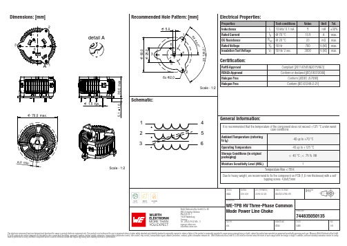
Dimensions: [mm]Scale - 1:2123456detail A1A744835050135Test Setup:744835050135744835050135T e m p e r a t u r eT T T 744835050135Cautions & Warnings:The following conditions apply to all goods within the product series of WE-TPBHV of Würth Elektronik eiSos GmbH & Co. KG:General:• This electronic component is designed and manufactured for use in general electronic equipment.•Würth Elektronik must be asked for written approval (following the PPAP procedure) before incorporating the components into any equipment in fields such as military, aerospace, aviation, nuclear control, submarine, transportation (automotive control, train control, ship control), transportation signal, disaster prevention, medical, public information network, etc. where higher safety and reliability are especially required and/or if there is the possibility of direct damage or human injury.•Electronic components that will be used in safety-critical or high-reliability applications, should be pre-evaluated by the customer. •The component is designed and manufactured to be used within the datasheet specified values. If the usage and operation conditions specified in the datasheet are not met, the wire insulation may be damaged or dissolved.•Do not drop or impact the components, the component may be damaged.•Würth Elektronik products are qualified according to international standards, which are listed in each product reliability report. Würth Elektronik does not warrant any customer qualified product characteristics beyond Würth Elektroniks’ specifications, for its validity and sustainability over time.•The responsibility for the applicability of the customer specific products and use in a particular customer design is always within the authority of the customer. All technical specifications for standard products also apply to customer specific products.Product specific:Soldering:•The solder profile must comply with the technical product specifications. All other profiles will void the warranty.•All other soldering methods are at the customers’ own risk.Cleaning and Washing:•Washing agents used during the production to clean the customer application might damage or change the characteristics of the wire insulation, marking or plating. Washing agents may have a negative effect on the long-term functionality of the product. Potting:•If the product is potted in the customer application, the potting material might shrink or expand during and after hardening. Shrinking could lead to an incomplete seal, allowing contaminants into the core. Expansion could damage the components. We recommend a manual inspection after potting to avoid these effects.Storage Conditions:• A storage of Würth Elektronik products for longer than 12 months is not recommended. Within other effects, the terminals may suffer degradation, resulting in bad solderability. Therefore, all products shall be used within the period of 12 months based on the day of shipment.•Do not expose the components to direct sunlight.•The storage conditions in the original packaging are defined according to DIN EN 61760-2.•The storage conditions stated in the original packaging apply to the storage time and not to the transportation time of the components. Packaging:•The packaging specifications apply only to purchase orders comprising whole packaging units. If the ordered quantity exceeds or is lower than the specified packaging unit, packaging in accordance with the packaging specifications cannot be ensured. Handling:•Violation of the technical product specifications such as exceeding the nominal rated current will void the warranty.•Applying currents with audio-frequency signals may result in audible noise due to the magnetostrictive material properties.•Due to heavy weight of the components, strong forces and high accelerations may have the effect to damage the electrical connection or to harm the circuit board and will void the warranty.•The temperature rise of the component must be taken into consideration. The operating temperature is comprised of ambient temperature and temperature rise of the component.The operating temperature of the component shall not exceed the maximum temperature specified.These cautions and warnings comply with the state of the scientific and technical knowledge and are believed to be accurate and reliable.However, no responsibility is assumed for inaccuracies or incompleteness.Würth Elektronik eiSos GmbH & Co. KGEMC & Inductive SolutionsMax-Eyth-Str. 174638 WaldenburgGermanyCHECKED REVISION DATE (YYYY-MM-DD)GENERAL TOLERANCE PROJECTIONMETHODHasA001.0012019-02-28DIN ISO 2768-1mDESCRIPTIONWE-TPB HV Three-Phase CommonMode Power Line Choke ORDER CODE744835050135SIZE/TYPE BUSINESS UNIT STATUS PAGEImportant NotesThe following conditions apply to all goods within the product range of Würth Elektronik eiSos GmbH & Co. KG:1. General Customer ResponsibilitySome goods within the product range of Würth Elektronik eiSos GmbH & Co. KG contain statements regarding general suitability for certain application areas. These statements about suitability are based on our knowledge and experience of typical requirements concerning the areas, serve as general guidance and cannot be estimated as binding statements about the suitability for a customer application. The responsibility for the applicability and use in a particular customer design is always solely within the authority of the customer. Due to this fact it is up to the customer to evaluate, where appropriate to investigate and decide whether the device with the specific product characteristics described in the product specification is valid and suitable for the respective customer application or not.2. Customer Responsibility related to Specific, in particular Safety-Relevant ApplicationsIt has to be clearly pointed out that the possibility of a malfunction of electronic components or failure before the end of the usual lifetime cannot be completely eliminated in the current state of the art, even if the products are operated within the range of the specifications.In certain customer applications requiring a very high level of safety and especially in customer applications in which the malfunction or failure of an electronic component could endanger human life or health it must be ensured by most advanced technological aid of suitable design of the customer application that no injury or damage is caused to third parties in the event of malfunction or failure of an electronic component. Therefore, customer is cautioned to verify that data sheets are current before placing orders. The current data sheets can be downloaded at .3. Best Care and AttentionAny product-specific notes, cautions and warnings must be strictly observed. Any disregard will result in the loss of warranty.4. Customer Support for Product SpecificationsSome products within the product range may contain substances which are subject to restrictions in certain jurisdictions in order to serve specific technical requirements. Necessary information is available on request. In this case the field sales engineer or the internal sales person in charge should be contacted who will be happy to support in this matter.5. Product R&DDue to constant product improvement product specifications may change from time to time. As a standard reporting procedure of the Product Change Notification (PCN) according to the JEDEC-Standard inform about minor and major changes. In case of further queries regarding the PCN, the field sales engineer or the internal sales person in charge should be contacted. The basic responsibility of the customer as per Section 1 and 2 remains unaffected.6. Product Life CycleDue to technical progress and economical evaluation we also reserve the right to discontinue production and delivery of products. As a standard reporting procedure of the Product Termination Notification (PTN) according to the JEDEC-Standard we will inform at an early stage about inevitable product discontinuance. According to this we cannot guarantee that all products within our product range will always be available. Therefore it needs to be verified with the field sales engineer or the internal sales person in charge about the current product availability expectancy before or when the product for application design-in disposal is considered. The approach named above does not apply in the case of individual agreements deviating from the foregoing for customer-specific products.7. Property RightsAll the rights for contractual products produced by Würth Elektronik eiSos GmbH & Co. KG on the basis of ideas, development contracts as well as models or templates that are subject to copyright, patent or commercial protection supplied to the customer will remain with Würth Elektronik eiSos GmbH & Co. KG. Würth Elektronik eiSos GmbH & Co. KG does not warrant or represent that any license, either expressed or implied, is granted under any patent right, copyright, mask work right, or other intellectual property right relating to any combination, application, or process in which Würth Elektronik eiSos GmbH & Co. KG components or services are used.8. General Terms and ConditionsUnless otherwise agreed in individual contracts, all orders are subject to the current version of the “General Terms and Conditions of Würth Elektronik eiSos Group”, last version available at .Würth Elektronik eiSos GmbH & Co. KGEMC & Inductive SolutionsMax-Eyth-Str. 174638 WaldenburgGermanyCHECKED REVISION DATE (YYYY-MM-DD)GENERAL TOLERANCE PROJECTIONMETHODHasA001.0012019-02-28DIN ISO 2768-1mDESCRIPTIONWE-TPB HV Three-Phase CommonMode Power Line Choke ORDER CODE744835050135SIZE/TYPE BUSINESS UNIT STATUS PAGE。
MODEL970-1036中文资料
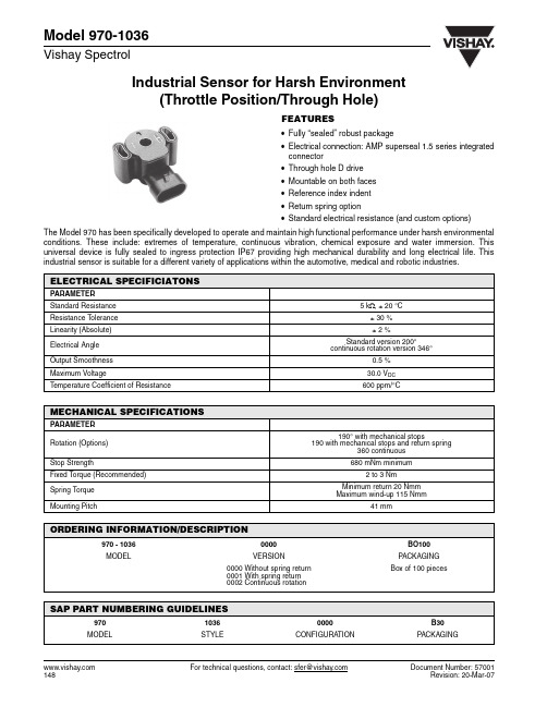
Industrial Sensor for Harsh Environment(Throttle Position/Through Hole)Model 970-1036Vishay Spectrol For technical questions, contact: sfer@Document Number: 57001FEATURES•Fully “sealed” robust package•Electrical connection: AMP superseal 1.5 series integrated connector•Through hole D drive •Mountable on both faces •Reference index indent •Return spring option•Standard electrical resistance (and custom options)The Model 970 has been specifically developed to operate and maintain high functional performance under harsh environmental conditions. These include: extremes of temperature, continuous vibration, chemical exposure and water immersion. This universal device is fully sealed to ingress protection IP67 providing high mechanical durability and long electrical life. Thisindustrial sensor is suitable for a different variety of applications within the automotive, medical and robotic industries.ELECTRICAL SPECIFICIATONSPARAMETER Standard Resistance 5 k Ω, ± 20 °C Resistance Tolerance ± 30 %Linearity (Absolute)± 2 %Electrical Angle Standard version 200°continuous rotation version 346°Output Smoothness 0.5 %Maximum Voltage30.0 V DC Temperature Coefficient of Resistance600 ppm/°CMECHANICAL SPECIFICATIONSPARAMETER Rotation (Options)190° with mechanical stops190 with mechanical stops and return spring360 continuousStop Strength680 mNm minimumFixed Torque (Recommended) 2 to 3 NmSpring Torque Minimum return 20 Nmm Maximum wind-up 115 NmmMounting Pitch41 mmORDERING INFORMATION/DESCRIPTION970 - 10360000BO100MODELVERSIONPACKAGING 0000 Without spring return 0001 With spring return 0002 Continuous rotationBox of 100 piecesSAP PART NUMBERING GUIDELINES97010360000B30MODELSTYLECONFIGURATIONPACKAGINGModel 970-1036Industrial Sensor for Harsh Environment(Throttle Position/Through Hole)Vishay SpectrolDocument Number: 57001For technical questions, contact: sfer@DIMENSIONS in inches (millimeters)ENVIRONMENTAL SPECIFICATIONSPARAMETER Vibration 15 g thru 2000 HzShock 50 gRotational Life 5000000 full cycles10000000 dither cycles (second rotation)Load Life900 h T emperature Range - 40 °C to + 130 °CSealing IP67Humidity 96 % at 40 °C (500 h)Salt Spray5 % solution at 40 °C (300 h)MARKINGUnit IdentificationManufacturer’s name and model number, resistance value, tolerance, data code and terminal identificationDisclaimer Legal Disclaimer NoticeVishayAll product specifications and data are subject to change without notice.Vishay Intertechnology, Inc., its affiliates, agents, and employees, and all persons acting on its or their behalf (collectively, “Vishay”), disclaim any and all liability for any errors, inaccuracies or incompleteness contained herein or in any other disclosure relating to any product.Vishay disclaims any and all liability arising out of the use or application of any product described herein or of any information provided herein to the maximum extent permitted by law. The product specifications do not expand or otherwise modify Vishay’s terms and conditions of purchase, including but not limited to the warranty expressed therein, which apply to these products.No license, express or implied, by estoppel or otherwise, to any intellectual property rights is granted by this document or by any conduct of Vishay.The products shown herein are not designed for use in medical, life-saving, or life-sustaining applications unless otherwise expressly indicated. Customers using or selling Vishay products not expressly indicated for use in such applications do so entirely at their own risk and agree to fully indemnify Vishay for any damages arising or resulting from such use or sale. Please contact authorized Vishay personnel to obtain written terms and conditions regarding products designed for such applications.Product names and markings noted herein may be trademarks of their respective owners.元器件交易网Document Number: 。
PS11036中文资料

Powerex, Inc., 200 Hillis Street, Youngwood, Pennsylvania 15697-1800 (724) 925-7272Intellimod™ ModuleApplication Specific IPM 30 Amperes/600 VoltsPS11036Description:Powerex Application Specific IPMs (ASIPMs) are inteligent power modules that integrate powerdevices, gate drive and protection circuitry in a compact package for use in small inverter applications up to 20kHz. Use of application specific HVICs allow the designer to reduce inverter size and overall design time.Features:□Compact Packages□3 Phase Converter Bridge Built-in□Integrated HVICs□Direct Connection to DSP/CPU Applications:□Small Motor Control □Small Servo Motors□General Purpose Inverters□Pump and HVAC Motor Control Ordering Information:PS11036 is a 600V , 30 Ampere Application SpecificIntelligent Power Module.DimensionsInches Millimeters A 3.74±0.0495.0±1.0B 2.91±0.0474.0±1.0C 0.32±0.028.0±0.5D 3.35±0.01285.0±0.3E 2.45±0.0362.35±0.8F 1.2431.6G 0.5714.5H 2.2056.0J 0.08 2.0K 0.9424.0L 0.7118.0M 0.020.4N 0.5915.0P 0.359.0Q 2.32±0.01259.0±0.3R1.3835.0DimensionsInches MillimetersS 0.10 2.5T 2.8071.0U 3.2382.1V 0.020.5W 0.25±0.012 6.35±0.3X 2.25±0.0357.15±0.8Y 0.08 2.0Z 0.14 3.5AA 0.65±0.0216.5±0.5BB 0.12±0.02 3.0±0.5CC 0.9323.5DD 1.21±0.0230.75±0.5EE 0.181 Dia. 4.6 Dia.FF 0.197 Dia. 5.0 Dia GG 0.020.5HH0.164.0Outline Drawing and Circuit DiagramPowerex, Inc., 200 Hillis Street, Youngwood, Pennsylvania 15697-1800 (724) 925-7272PS11036Intellimod™ ModuleApplication Specific IPM30 Amperes/600 VoltsAbsolute Maximum Ratings, T j = 25°C unless otherwise specifiedCharacteristics Symbol PS11036Units Power Device Junction T emperature*T j-20 to 125°C Storage Temperature T stg-40 to 125°C Case Operating Temperature (See T C Measure Point Illustration)T C-20 to 100°C Mounting Torque, M4 Mounting Screws—13in-lb Module Weight (Typical)—105Grams Isolation Voltage**V ISO2500Volts *The indicated values are specified considering the safe operation of all the parts within the ASIPM. The maximum rating for the ASIPM power chips (IGBT & FWDi) is T j < 150.**60 Hz sinusoidal AC applied between all terminals and the base plate for 1 minute.IGBT Inverter SectorSupply Voltage (Applied between P2 - N2)V CC450Volts Supply Voltage, Surge (Applied between P2 - N2, Surge-Value)V CC(surge)500Volts Each IGBT Collector-Emitter Static Voltage (Applied between P2-U.V.W, U.V.W-N2)V P or V N600Volts Each IGBT Collector-Emitter Switching Voltage V P(S) or V N(S)600Volts (Applied between P2-U.V.W, U.V.W-N2 (Pulse))Each IGBT Collector Current, T C = 25°C, “( )” means I C Peak Value±I C(±I CP)±30 (±60)AmperesConverter SectorRepetitive Peak Reverse Voltage V RRM800Volts Recommended AC Input Voltage E a220Vrms DC Output Current (3-phase Rectifying Circuit)I DC30 A Surge (Non-repetitive) Forward Current (1 Cycle at 60Hz, Peak Value Non-repetitive)I FSM300AI2t for Fusing (Value for One Cycle of Surge Current)I2t375A2sControl SectorSupply Voltage V D,V DB-0.5 ~ 20Volts Input Signal Voltage V CIN-0.5 ~ 7.5Volts Fault Output Supply Voltage V FO-0.5 ~ 7.5Volts Fault Output Current I FO15mA DC-Link IGBT Current Signal Amp Output Current I AMP1mAPowerex, Inc., 200 Hillis Street, Youngwood, Pennsylvania 15697-1800 (724) 925-7272PS11036Intellimod™ ModuleApplication Specific IPM30 Amperes/600 VoltsElectrical and Mechanical Characteristics, T j = 25°C unless otherwise specifiedCharacteristics Symbol Test Conditions Min. Typ.Max.UnitsIGBT Inverter SectorCollector-Emitter Saturation Voltage V CE(sat)I C = 30A, T j = 25°C, V D = V DB = 15V,—— 2.9VoltsInput = ON (Shunt Voltage Drop Not Included)Diode Forward Voltage V EC T j = 25°C, -I C = 30A—— 2.9Volts Converter Diode Voltage V FR T j = 25°C, I FR = 10A—— 1.5Volts Converter Diode Reverse Current I RRM V R = V RRM, T j = 125°C——8mA Switching Times onC(on)CC C joff D DBC(off)on offrrShort Circuit Endurance (Output, Arm, and@V CC≤ 400V, Input = 5V → 0V (One-shot),• No DestructionLoad Short-Circuit Modes) -20°C ≤ T j(start)≤ 125°C,• F O Output by Protection Operation13.5V ≤ V D = V DB≤ 16.5VSwitching SOA @V CC≤ 400V, Input = 5V → 0V,• No DestructionT j≤ 125°C, I C < OC T rip Level,• No Protecting Operation13.5V ≤ V D = V DB≤ 16.5V• No F O OutputT C Measure PointCPowerex, Inc., 200 Hillis Street, Youngwood, Pennsylvania 15697-1800 (724) 925-7272PS11036Intellimod™ ModuleApplication Specific IPM30 Amperes/600 VoltsElectrical and Mechanical Characteristics, T j = 25°C unless otherwise specifiedCharacteristics Symbol Test Conditions Min. Typ.Max.UnitsControl SectorCircuit Current (Average)I D T j = 25°C, V D = 15V, V IN = 5V——50mAI DB T j = 25°C, V D = V DB = 15V, V IN = 5V——5mA Input ON Threshold Voltage V th(on)0.8 1.4 2.0Volts Input OFF Threshold Voltage V th(off) 2.5 3.0 4.0Volts Input Pull-up Resistor Ri Applied between—50—kΩInput Terminal-inside Power SupplyPWM Input Frequency f PWM T C≤ 100°C, T j≤ 125°C1—15kHz Arm Shoot-through Blocking Time*t DEAD Relates to Corresponding Inputs 2.2——µST C = -20°C ~ 100°CInput Interlock Sensing t int Relates to Corresponding Input—100—ns Inverter DC-link IGBT Current V amp 100%I C = I OP(100%), V D = 15V, T j = 25°C 1.5 2.0 2.5Volts Sense Voltage Output Signal** V amp 200%I C = I OP(200%), V D = 15V, T j = 25°C 3.0 4.0 5.0Volts Inverter DC-link IGBT Current V amp 250%I C = I OP(250%), V D = 15V 5.0——Volts Sense Voltage Output Limit** V amp 0%I C = I OP(0%), V D = 15V—50100mV Over-Current Trip Level OC31.139.060.0AmperesOC jShort-Circuit Trip Level SC—60—AmperesSCTrip Level UV D11.012.013.0Volts Supply Circuit Reset Level UV Dr11.512.513.5Volts Under-Voltage DB C jProtection Reset Level UV DBr10.611.312.1Volts Delay Time t dV—10—µS Fault Output Pulse Width***t FO T j = 25°C 1.0 1.8—mS Fault Output Current***I Fo(H)Open Collector Output——1µAFo(L)* The dead-time has to be set externally by the CPU; it is not part of the ASIPM internal functions.**Refer ro the graph on next page.***Fault output signalling is given only when the internal OC, SC, and UV protection circuits are activated. The OC, SC and UV protection (and fault output) operate for the lower arms only. The OC and SC protection fault output is given in a pulse format while that of UV protection is maintained thrpughout the duration of the under-voltage condition.PS11036Intellimod ™ ModuleApplication Specific IPM 30 Amperes/600 VoltsPowerex, Inc., 200 Hillis Street, Youngwood, Pennsylvania 15697-1800 (724) 925-7272Thermal CharacteristicsCharacteristic Symbol Condition Min. Typ.Max.Units Junction to CaseR th(j-c)Q Each IGBT —— 1.5°C/Watt R th(j-c)D Each FWDi —— 2.4°C/Watt R th(j-c)DREach Converter —— 2.0°C/Watt Contact Thermal ResistanceR th(c-f)Case to Fin Per Module.——0.042°C/WattThermal Grease AppliedRecommended Conditions for UseCharacteristic Symbol ConditionMin.Typ.Value Units Supply Voltage V CCApplied across P2-N2 Terminals —300400Volts Control Supply VoltageV D Applied between V D -GND 13.515.016.5Volts V DBApplied between CBU+ & CBU-,13.515.016.5VoltsCBV+ & CBV-, CBW+ & CBW-Control Supply dv/dt dV D /dt, dV DB /dt-1—1V/µs Input ON Voltage V CIN(on)Applied between 0—0.8Volts CIN(off)P P P N N N Module Case Operating Temperature T C ——100°C PWM Input Frequencyf PWM T C ≤ 100°C, T j ≤ 125°C ——15kHz Allowable Minimum Input On-pulse Width t XX 1——µS Arm Shoot-through Blocking Timet DEADRelate to Corresponding Inputs2.2——µSC U R R E N T S E N SE V O L T A G EO U T P U T S I G N A L ,V A M P , (V O L T S )INVERTER DC-LINK IGBT CURRENT ANALOG SIGNALING (TYPICAL)510020043210300ACTUAL LOAD PEAK CURRENT, (%), (I C = I O X ͌2 )PS11036Intellimod ™ ModuleApplication Specific IPM 30 Amperes/600 VoltsPowerex, Inc., 200 Hillis Street, Youngwood, Pennsylvania 15697-1800 (724) 925-72722112–+–+–+V DU P V P W U N V N W F V Functional Block Diagram。
JET 3-1 2 吨耐力杆式抬升机产品说明书

Operating Instructions and Parts Manual3-1/2 ton Farm JackModel FJ-3-1/2AJET427 New Sanford RoadLaVergne, Tennessee 37086 Part No. M-440436 Ph.: 800-274-6848 Revision A1 06/2014 Copyright © 2014 JET1.0 Warranty and ServiceJET® warrants every product it sells against manufacturers’ defects. If one of our tools needs service or repair, please contact Technical Service by calling 1-800-274-6846, 8AM to 5PM CST, Monday through Friday.Warranty PeriodThe general warranty lasts for the time period specified in the literature included with your product or on the official JET branded website.•JET products carry a limited warranty which varies in duration based upon the product. (See chart below) •Accessories carry a limited warranty of one year from the date of receipt.•Consumable items are defined as expendable parts or accessories expected to become inoperable within a reasonable amount of use and are covered by a 90 day limited warranty against manufacturer’s defects. Who is CoveredThis warranty covers only the initial purchaser of the product from the date of delivery.What is CoveredThis warranty covers any defects in workmanship or materials subject to the limitations stated below. This warranty does not cover failures due directly or indirectly to misuse, abuse, negligence or accidents, normal wear-and-tear, improper repair, alterations or lack of maintenance.Warranty LimitationsWoodworking products with a Five Year Warranty that are used for commercial or industrial purposes default to a Two Year Warranty. Please contact Technical Service at 1-800-274-6846 for further clarification.How to Get Technical SupportPlease contact Technical Service by calling 1-800-274-6846. Please note that you will be asked to provide proof of initial purchase when calling. If a product requires further inspection, the Technical Service representative will explain and assist with any additional action needed.JET has Authorized Service Centers located throughout the United States. For the name of an Authorized Service Center in your area call 1-800-274-6846 or use the Service Center Locator on the JET website.More InformationJET is constantly adding new products. For complete, up-to-date product information, check with your local distributor or visit the JET website.How State Law AppliesThis warranty gives you specific legal rights, subject to applicable state law.Limitations on This WarrantyJET LIMITS ALL IMPLIED WARRANTIES TO THE PERIOD OF THE LIMITED WARRANTY FOR EACH PRODUCT. EXCEPT AS STATED HEREIN, ANY IMPLIED WARRANTIES OF MERCHANTABILITY AND FITNESS FOR A PARTICULAR PURPOSE ARE EXCLUDED. SOME STATES DO NOT ALLOW LIMITATIONS ON HOW LONG AN IMPLIED WARRANTY LASTS, SO THE ABOVE LIMITATION MAY NOT APPLY TO YOU.JET SHALL IN NO EVENT BE LIABLE FOR DEATH, INJURIES TO PERSONS OR PROPERTY, OR FOR INCIDENTAL, CONTINGENT, SPECIAL, OR CONSEQUENTIAL DAMAGES ARISING FROM THE USE OF OUR PRODUCTS. SOME STATES DO NOT ALLOW THE EXCLUSION OR LIMITATION OF INCIDENTAL OR CONSEQUENTIAL DAMAGES, SO THE ABOVE LIMITATION OR EXCLUSION MAY NOT APPLY TO YOU.JET sells through distributors only. The specifications listed in JET printed materials and on official JET website are given as general information and are not binding. JET reserves the right to effect at any time, without prior notice, those alterations to parts, fittings, and accessory equipment which they may deem necessary for any reason whatsoever. JET® branded products are not sold in Canada by JPW Industries, Inc.Product Listing with Warranty Period90 Days – Parts; Consumable items; Light-Duty Air Tools1 Year – Motors; Machine Accessories; Heavy-Duty Air Tools; Pro-Duty Air Tools2 Year – Metalworking Machinery; Electric Hoists, Electric Hoist Accessories5 Year – Woodworking MachineryLimited Lifetime – JET Parallel clamps; VOLT Series Electric Hoists; Manual Hoists; Manual HoistAccessories; Shop Tools; Warehouse & Dock products; Hand ToolsNOTE: JET is a division of JPW Industries, Inc. References in this document to JET also apply to JPW Industries, Inc., or any of its successors in interest to the JET brand.2.0 Table of contentsSection Page1.0 Warranty and Service (2)2.0 Table of contents (3)3.0 About this jack and manual (3)4.0 Safety warnings (4)5.0 Features and Terminology (5)6.0 Specifications (6)6.1 Base hole centers (6)7.0 Lubrication (7)8.0 Pre-Operation Inspection (7)9.0 Operation (7)9.1 Lifting (7)9.2 Winching (8)9.3 Clamping (8)10.0 Storage (8)11.0 Replacement Parts (10)11.1.1 FJ-3-1/2A Farm Jack – Exploded View (10)11.1.2 FJ-3-1/2A Farm Jack – Parts List (11)3.0 About this jack and manualThe JET Model FJ-3-1/2A Farm Jack is a multi-purpose mechanical tool with the functions of a jack, hoist, winch, crane, and clamp. It is simple and easy to operate, inspect and service, and is especially suited for field operations. With regular maintenance your JET Farm Jack will provide years of dependable service.The jack is manufactured to high quality standards in compliance with ANSI/ASME B30.1 safety standards. This manual is provided by JET covering the safe operation and maintenance procedures for the JET Farm Jack. This manual contains instructions on set-up, safety precautions, general operating procedures, maintenance instructions and parts breakdown.If there are questions or comments, please contact your local supplier or JET. JET can also be reached at our web site: .Retain this manual for future reference. If the jack transfers ownership, the manual should accompany it.Read and understand the entire contents of this manual before attempting assembly or operation! Failure to comply may cause serious injury!4.0 Safety warnings1. Read and understand the entire owner'smanual before attempting assembly or operation.2. Read and understand the warnings posted onthe jack and in this manual. Failure to complywith all of these warnings may cause seriousinjury.3. Replace warning labels if they becomeobscured or removed.4. This jack is designed and intended for use byproperly trained and experienced personnelonly. If you are not familiar with the proper andsafe operation of a farm jack, do not use untilproper training and knowledge have beenobtained.5. Visually inspect and check operation of jackprior to each use.6. Use on hard, level surface only when using asa jack.7. Always keep jack clean and oiled. Front andback of rail must be kept free from rust. Jackwill not operate safely without proper lubrication.8. Improper use of this jack may be highlyhazardous and may cause serious injury ordeath.9. Do not exceed rated capacities of the jack.10. Lifting capacity decreases as lifting nosedistance from base increases.11. Always chock and block (stabilize) load to belifted, as jack will not stabilize load to prevent itfrom falling.12. Never use jack on curved or tubular bumpers.The vehicle could slide off the jack and fallcausing serious injury or death.13. Never attempt to raise more than one wheel ata time and do not lift wheel more than 2"above the ground.14. Never work under a raised load unless loadhas been transferred to jack stands or suitablesupports. As a precaution, insert 1/2-inchdiameter bolt (not included) into rail immediately below lifting mechanism.15. Always place handle in upright position until itcatches, before tripping the reversing latch tolower load. This will prevent handle from moving up or down rapidly, which could causeserious or fatal injury if handle comes into contact with your head or body.16. Always keep your head away from travel pathof handle.17. Always keep a firm grip with both hands onhandle when using this jack. Maintain firm footing and balance while pumping handle. 18. Improper lowering of loads can be dangerous.During lowering, the weight of the load pushesup against the handle. If your hands slip off thehandle, or the handle is in horizontal position when you trip the reverse latch, it may move up very fast. If your head is in the travel path ofthe handle, it could strike you causing seriousor fatal injury.19. Place complete lifting nose under object to belifted, to prevent shifting of load.20. Do not drop weight onto lifting nose.21. All persons must stay clear of load being lifted,lowered, pulled, winched or clamped.22. If raised load falls, it can cause serious injuryor death.23. Never push lifted load off jack.24. Jack must be loaded with 50kg (110 lb) ormore to lower load step-by-step. Otherwise lifting nose (and load) will drop.25. If any part of the jack fails to work properly,discontinue use and have jack repaired at an authorized JET service center.26. Never attempt to repair jack while jack is underload.27. Do not modify jack.28. Do not use extension on handle. Warranty isvoid if handle extension is used.29. Always use genuine factory replacement partsonly.30. When operating tools, wear impact-resistantprotective eyewear with side shields that meets ANSI Z87.1 requirements.31. Do not operate this tool while tired or under theinfluence of drugs, alcohol or any medication which might impair your judgment.32. Failure to comply with all of these warningsmay result in loss of load, damage to jack, personal injury and/or property damage.Familiarize yourself with the following safety notices used in this manual:This means that if precautions are not heeded, it may result in minor injury and/or possible tool damage.This means that if precautions are not heeded, it may result in serious injury or possibly even death.5.0 Features and TerminologyFigure6.0 SpecificationsModel number ......................................................................................................................................... FJ-3-1/2AStock number (440436)Capacities: Liftcapacity(Rated capacity established with load at 1 foot height)...................................... 3200 kg (7000 lb)...................................................................................................... 2500 kg (5,500 lb)capacityWinching/pullingcapacity ...................................................................................................................... 350 kg (770 lb)ClampingMinimum lifting nose height....................................................................................................... 110 mm (4.3 in)Maximum lifting nose height............................................................................................... 1030 mm (40-1/2 in)Lift per handle stroke................................................................................................................... 19 mm (3/4 in)Total travel of running gear assembly along rail (approximate) ...................................................... 92 cm (3 ft.)Materials: Runner body......................................................................................................................................... cast iron............................................................................................................................................................. steelRailpins............................................................................................................................ zinc plated steelClimbingHandle........................................................................................................................................................ steel......................................................................................................................................... zinc plated steelBaseReversing........................................................................................................................ zinc plated steellatchfinish...................................................................................................................................... powder-coatPaintDimensions and Weights: ........................................................................................... 1230 x 50 x 10 mm (48 x 2 x 0.4 in)Rail(LxWxThk)(LxW) .................................................................................................... 100 x 37 mm (4 x 1-1/2 in)noseLiftingLifting nose hole diameter ......................................................................................................... 14 mm (0.55 in)................................................................................................................. 14 mm (0.55 in)(diameter)holesRaildimensions .................................................................................................... 180 x 115 mm (7 x 4-1/2 in)Base............................................................................................................................. 750 mm (30 in)lengthHandle....................................................................................................................... 32 mm (1-1/4 in)HandlediameterShipping carton dimensions (LxWxH) ................................................. 124 x 24 x 14 cm (49 x 9-1/2 x 5-1/2 in)...................................................................................................................................... 13 kg (29 lb)Netweight.............................................................................................................................. 16 kg (35 lb)weightShippingThe specifications in this manual were current at time of publication, but because of our policy of continuousimprovement, JET, reserves the right to change specifications at any time and without prior notice, without incurringobligations.6.1 Base hole centersFigure 27.0 LubricationKeep jack clean and oiled. Use a light penetrating oil, or silicone spray – do not use grease or motor oils. Before every operation, inspect and make sure the following areas of the jack are lubricated (Figure 3).Lubrication of these parts is essential to ensure proper jack operation and will prolong the life of the jack.1. Front and back edges of rail. Keep edges ofrail free from rust.2. Upper clevis pin3. Cross pins4. Lower clevis pin5. Climbing pins and springs6. Reversing latch and pivot bolt7. Reversing latch spring.Figure 38.0 Pre-Operation InspectionPrior to operation, test jack on a hard level surface with no load. Pay close attention to climbing pin and complete running gear assembly operation. There should be no binding of moving parts.Make sure there are no cracks or bends in the rail, the handle, or the running gear assembly. Climbing pins and springs should be in good condition. Rail holes should be clear of obstructions.If a problem is found with the jack, do not use until problem has been resolved. 9.0 Operation9.1 LiftingDo not exceed the 7000 lb lift capacity. Do not use jack to support the load. Do not raise more than one wheel per lift, and no higher than 2-inches from ground. Chock and block (stabilize) load prior to lift. Never get under a load without jack stands or other suitable support. Never use jack on curved or tubular bumpers. Always place handle completely upright before tripping reversing latch – this will prevent handle from swinging up rapidly, which could cause serious or fatal injury if it contacts your head or body. Always use two hands with firm grip on handle and keep head out of travel path of handle. Always lower load slowly with extreme caution. Failure to comply may cause serious injury or death.1. Place jack base on hard, level surface capableof supporting the jack and the load to be lifted. 2. Position handle upright until it secures in thecatch on the running gear assembly.3. Lift reversing latch until it locks in raisedposition. Pull straight up on handle to raiselifting nose into contact with load (pumpinghandle not necessary).4. Place entire lifting nose under object to belifted, to prevent load shifting during operation.Rail must be pointing straight up.5. Always keep a firm grip with both hands on thehandle. Pump handle slowly to raise jack (loadlifts on each down-stroke). Climbing pinsshould alternately engage rail for proper step-by-step operation.6. Always chock and block (stabilize) load, asjack itself will not stabilize load. This willprevent load from shifting or rolling as you lift.Keep all persons clear from load being raisedor lowered.7. Never work under a raised load unless loadhas been transferred to jack stands or othersuitable supports.8. Insert a grade-5, 1/2" bolt (not included)through a hole in the rail immediately belowlifting mechanism, as a safety precaution.9. Always keep handle upright when notoperating jack.To lower jack:10. Position handle upright until it catches. Pushreversing latch downward. NOTE: Jack musthave 50kg (110lb) load minimum to lower jackstep-by-step, otherwise lifting nose will dropimmediately.11. Pump handle with both hands firmly and slowlyfor proper step-by-step operation (load lowerson each up-stroke), until load is completelylowered.Note: Load will produce upward pressure onthe handle.9.2 WinchingDo not exceed the 5500 lb. winching capacity, or damage to jack and/or personal injury may occur. Working load of each chain or strap must be greater than the jack winching capacity. Exceeding winching capacity may cause top clamp clevis to bend or break causing load to shift, or the chain/strap to snap back, resulting in injury and/or property damage.Refer to Figure 4.The procedure below is based upon more travel being needed beyond the jack length, and involves attachment of a third chain or strap to act as tensioner while repositioning runner assembly. If the travel required is less than total travel of jack runner, a third chain or strap will not be needed.1. Position top clamp clevis parallel to rail andsecure with nut (18mm or adjustable wrench). 2. Remove base if necessary (13mm oradjustable wrench), and attach one end of atensioner chain or strap to a hole in the rail.Reinstall base.3. Securely attach one end of another chain orstrap to the load (object to be winched).Secure opposite end of chain/strap to top clamp clevis on jack. If chain/strap won’t fitthrough hole of clevis, use a shackle.4. Position runner assembly at beginning of itstravel along the rail.5. Secure a third chain/strap to a fixed object,and connect its opposite end to lifting nose ofjack.6. Begin winching, using similar procedure to thatof lifting (section 9.1).7. When runner assembly reaches end of travel,hook tensioner chain as far back as possibletoward fixed object. 8. Trip reversing latch, allowing the tension to beabsorbed by tensioner chain.9. Return runner assembly to beginning of travel,and reconnect fixed object chain without slackas far behind tensioner chain as possible.10. Begin winching again. The tensioner chain willslacken.11. Repeat process as needed.9.3 ClampingDo not exceed the 770 lb. clamping capacity, or damage to jack and/or personal injury may occur. Exceeding clamping capacity may cause top clamp clevis to bend or break resulting in injury and/or property damage.Refer to Figure 5.1. Securely fasten top clamp clevis in 90°position to rail. The top clamp clevis may besecured to any hole along the rail.2. Object should be centered between top clampclevis and lifting nose.3. Pump handle as needed to clamp object inplace.10.0 Storage1. Lower lifting nose completely.2. Position handle upright until it catches.3. Lift reversing latch until it locks in "up" position.4. Store jack in upright position, preferablyindoors in a clean and dry location. If storedoutdoors, use suitable cover to protect jack from moisture.Figure 4 Winching operationFigure 5 Clamping operation11.0 Replacement PartsTo order parts or reach our service department, call 1-800-274-6848 Monday through Friday (see our website for business hours, ). Having the Model Number and Serial Number of your machine available when you call will allow us to serve you quickly and accurately.11.1.1 FJ-3-1/2A Farm Jack – Exploded View11.1.2 FJ-3-1/2A Farm Jack – Parts ListIndex No Part No Description Size Qty1 ................ TS-1492041 .............. Hex Cap Screw ........................................................ M12 x 40 .. (1)2 ................ FJ3A-2....................... Top Clamp Clevis .................................................... .. (1)3 ................ FJ3A-3....................... Rail........................................................................... .. (1)4 ................ TS-2360121 .............. Flat Washer ............................................................. M12 . (5)5 ................ TS-1540081 .............. Hex Nut .................................................................... M12 . (1)6 ................ FJ3A-6....................... Large Runner ........................................................... .. (1)7 ................ TS-2342121 .............. Lock Nut................................................................... M12 . (1)8 ................ FJ3A-8....................... Cotter Pin ................................................................. Ø2.5x30 mm .. (2)9 ................ FJ3A-9....................... Handle ..................................................................... .. (1)10 .............. FJ3A-10..................... Rubber Grip ............................................................. .. (1)11 .............. FJ3A-11..................... Connecting Arm ....................................................... .. (1)12 .............. FJ3A-12..................... Lower Clevis Pin ...................................................... .. (1)13 .............. TS-1490051 .............. Hex Cap Screw ........................................................ M8x30 (1)14 .............. FJ3A-14..................... Base......................................................................... .. (1)15 .............. TS-1550061 .............. Flat Washer ............................................................. M8 (1)16 .............. FJ3A-16..................... Hex Nut .................................................................... M8-L (1)17 .............. FJ3A-17..................... Small Runner ........................................................... .. (1)18 .............. FJ3A-18..................... Climbing Pin Spring ................................................. .. (2)19 .............. FJ3A-19..................... Climbing Pin............................................................. .. (2)20 .............. FJ3A-20..................... Cross Pin ................................................................. Ø5x60 mm .. (2)21 .............. FJ3A-21..................... Reversing Latch Cam Bar........................................ .. (1)22 .............. FJ3A-22..................... Reversing Latch Spring ........................................... .. (1)23 .............. FLJ45-4 ..................... Hex Cap Screw ........................................................ M8x15 (1)24 .............. TS-1550061 .............. Flat Washer ............................................................. M8 (1)25 .............. FJ3A-25..................... Reversing Latch ....................................................... .. (1)26 .............. TS-1492071 .............. Hex Cap Screw ........................................................ M12x70 . (1)27 .............. FJ3A-27..................... Upper Clevis Pin ...................................................... .. (1).................. FJ3A-28..................... Complete Running Gear Assembly (includes #4,6-12,17-27) (1).................. FJ3A-ID ..................... I.D. Label (not shown).............................................. .. (1).................. FJ3-WL...................... Warning Label (not shown) ...................................... .. (1)427 New Sanford Road LaVergne, Tennessee 37086 Phone: 800-274-6848。
美国凯斯西储大学轴承大数据说明书
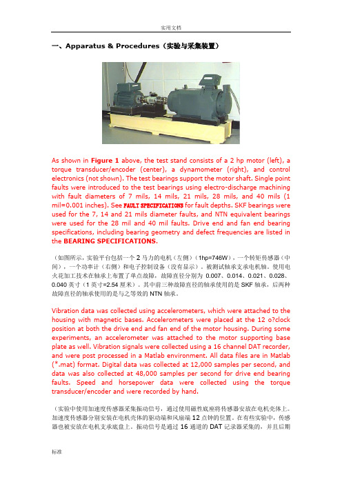
一、Apparatus & Procedures(实验与采集装置)As shown in Figure 1 above, the test stand consists of a 2 hp motor (left), a torque transducer/encoder (center), a dynamometer (right), and control electronics (not shown). The test bearings support the motor shaft. Single point faults were introduced to the test bearings using electro-discharge machining with fault diameters of 7 mils, 14 mils, 21 mils, 28 mils, and 40 mils (1 mil=0.001 inches). See FAULT SPECIFICATIONS for fault depths. SKF bearings were used for the 7, 14 and 21 mils diameter faults, and NTN equivalent bearings were used for the 28 mil and 40 mil faults. Drive end and fan end bearing specifications, including bearing geometry and defect frequencies are listed in the BEARING SPECIFICATIONS.(如图所示,实验平台包括一个2马力的电机(左侧)(1hp=746W),一个转矩传感器(中间),一个功率计(右侧)和电子控制设备(没有显示)。
- 1、下载文档前请自行甄别文档内容的完整性,平台不提供额外的编辑、内容补充、找答案等附加服务。
- 2、"仅部分预览"的文档,不可在线预览部分如存在完整性等问题,可反馈申请退款(可完整预览的文档不适用该条件!)。
- 3、如文档侵犯您的权益,请联系客服反馈,我们会尽快为您处理(人工客服工作时间:9:00-18:30)。
61~}8595.>?<14534;:A1<7.>/4593<17.B
8;=
888
J_ma^Zf[b^g\^Zeehpl2_enq ikhh_^]bl ik^_^k^gmbZeer k^\hff^g]^]4
80KF76bl Zg^gobkhgf^gmZe_kb^g]er ikh]n\m4Pe^Zl^fZkd Z li^\bZe\h]^/;;;0hk/;;70pa^g hk]^kbg`4/;;70lmZg]l RhIS\hfiebZgm pbma DZ]fbnf\hgmZ\mA/;;;0lmZg]l_hk RhIS\hfiebZgm pbma DZ]fbnf3_k^^\hgmZ\m4
90Bl mh pZla mb`am mri^2[^_hk^nlbg`k^eZr2ie^Zl^k^fho^ma^o^gm iZkm hg ma^mhi h_ma^\ho^k4
:0Dhglb]^kbg`ma^bgbmbZe lmZm^fb`am[^\aZg`^]bg mkZglbm/m^kfbgZe9,Zg]:,bl hi^gbg`[r]^_Znem02nihg k^jnb^]2ihlbmbhg lahne][^l^m hk k^l^m4 ;0Bl mh eZfi ehZ]2\ZiZ\bmbo^ehZ]2fhmhk ehZ]hk lhf^h\\Zlbhg Zldbg`_hk Z\\hk]bg`pbma RhIS2ie^Zl^\ahhl^B`SgO8\hgmZ\m fZm^kbZe4
R^fZkd@Jg\Zl^h_gh mhe^kZg\^lahpg bg hnmebg^]bf^glbhg@hnmebg^]bf^glbhg X7ff2mhe^kZg\^lahne][^u648ffA hnmebg^]bf^glbhg Z7ff Zg]X;ff2mhe^kZg\^lahne][^u649ffA hnmebg^]bf^glbhg Z;ff2mhe^kZg\^lahne][^u64:ff4
8;>
Onmebg^Ebf^glbhgl
:?>759105819=5:9=.90A5<59305.3<.8Ugbm@ff
/Chmmhf ob^p0
Ebl\eZbf^k
Tabl ]ZmZla^^m bl _hk ma^\nlmhf^klw k^_^k^g\^4Bee ma^li^\b_b\Zmbhgl Zk^ln[c^\m mh \aZg`^pbmahnm ghmb\^4
W^\hne]ghm ^oZenZm^Zee ma^i^k_hkfZg\^Zg]Zee ma^iZkZf^m^kl _hk ^o^kr ihllb[e^Ziieb\Zmbhg4Tanl ma^nl^k lahne][^bg Z kb`am ihlbmbhg mh \ahhl^ma^lnbmZ[e^ikh]n\m _hk ma^bk hpg Ziieb\Zmbhg4J_ma^k^bl Zgr jn^kr2ie^Zl^\hgmZ\m Ihg`_Z _hk ma^m^\agb\Ze l^kob\^4Ihp^o^k2bm bl ma^nl^kwl k^lihglb[bebmr mh ]^m^kfbg^pab\a ikh]n\m lahne][^nl^]hger4
t XbZf^g Ihg`_Z Fe^\mkhZ\hnlmb\Dh42Lm]4Bee kb`aml h_Ihg`_Z Zk^k^l^ko^]4
9NRJEG
74R^eZr bl hg ma^xl^my lmZmnl pa^g [^bg`k^e^Zl^]_khf lmh\d2pbma ma^\hglb]^kZmbhg h_lah\d kbl^g _khf mkZglbm Zg]k^eZr fhngmbg`2k^eZr phne][^\aZg`^]mh xk^l^my lmZmnl2ma^k^_hk^2pa^g Ziieb\Zmbhg /\hgg^\mbg`ma^ihp^k lniier02ie^Zl^k^l^m ma^k^eZr mh xl^my hk xk^l^my lmZmnl hg k^jn^lm484Jg hk]^k mh fZbgmZbg xl^my hk xk^l^my lmZmnl2^g^k`bs^]ohemZ`^mh \hbe lahne]k^Z\a ma^kZm^]ohemZ`^2bfinel^pb]ma lahne][^;mbf^l fhk^maZg xl^my hk xk^l^my mbf^4Eh ghm ^g^k`bs^ohemZ`^mh xl^my \hbe Zg]xk^l^my \hbe lbfnemZg^hnler4Bg]Zelh ehg`^g^k`bs^]mbf^/fhk^maZg 7fbg0lahne][^Zohb]^]4
94Jg hk]^k mh Zohb]\aZg`bg`hi^kZm^ohemZ`^2ikh]n\ml lahne]ghm [^d^im bg lmkhg`fZ`g^mb\_b^e]]nkbg`mkZglihkmZmbhg2lmhkZ`^Zg]Ziieb\Zmbhg4
8;?
/Chmmhf ob^p0
:?>759105819=5:9=.90A5<59305.3<.8
Ugbm@ff
Wbkbg`EbZ`kZf
SmZg]Zk]iheZkbmr /R^l^m \hg]bmbhg0
Sbg`e^\hbe27Ghkf B
Ehn[e^\hbe27Ghkf B
Sbg`e^\hbe27Ghkf D Ehn[e^\hbe27Ghkf D
D。