Bosch Automated Driving
bosch博世公司介绍
博世汽车柴油系统股份有限公司 地址:江苏省无锡市新区新华路17号 邮编:214028 电话:+86 510 8533-3888 传真:+86 510 8533-8000 Bosch Automotive Diesel Systems Co., Ltd. 17 Xinhua Road, New District, Wuxi 214028, Jiangsu, P.R. China Tel. +86 510 8533-3888 Fax +86 510 8533-8000 博世汽车柴油系统股份有限公司Bosch Automotive Diesel Systems Co., Ltd.清洁柴油动力Clean Diesel Power致辞 Foreword无论您何时何地需要我们,我们都将倾力服务目录 Content致辞柴油发动机的历史总是和博世这个名字紧密联结在一起。
作为先驱者 以及全球发动机和汽车生产厂商的主要合作伙伴和系统供应商,博世 以其持续不断的技术创新,精益求精的产品和杰出的系统解决方案而 闻名于世。
全球有超过58,000名积极的并受到良好教育的柴油系统 员工在为客户的成功而竭心尽力。
博世全力支持中国汽车工业的强劲发展。
作为博世柴油系统在中国的 能效中心,博世汽车柴油系统股份有限公司凭借丰富的经验和先进的 技术在中国汽车工业中扮演着积极的角色。
拥有先进技术中心的博世Where you need us, we are there The history of the Diesel engine has always been closely linked to the name “Bosch”. Being the pioneer, the leading partner and systems' supplier for all engine and vehicle manufacturers worldwide, Bosch is well known for its consistent innovations, advanced and reliable products and excellent system solutions. More than 58,000 highly motivated and well educated diesel associates worldwide are dedicated to the success of the customers. The strong momentum of the Chinese automotive market is fully supported by Bosch. As our Diesel competence center in China, Bosch Automotive Diesel Systems Co., Ltd. is taking an active role in the Chinese automotive industry through our expertise and advanced technology. The company with its state-of-the-art Technical Center Diesel is responsible for development, application, production and sales to serve our local customers. To achieve both a higher mobility and sustainable growth for China, Bosch has the solution!Foreword柴油系统1汽车柴油系统股份有限公司,负责柴油项目的开发、匹配、生产和销 售,致力于为本地客户提供最优质的服务。
德国采埃孚集团最新介绍
Divisions Car Driveline Technology Car Chassis Technology Commercial Vehicle and Special Driveline Technology Off-Road Driveline Technology and Axle Systems Powertrain and Suspension Components Steering Technology – ZF Lenksysteme GmbH
Total sales 787 mio. €
Car Driveline Technology 16%
Car Chassis Technology 34%
Off-Road Driveline Technology
and Axle Systems
11%
2009/06
ZF in China
11
ZF Group
Hydraulic power steering systems for CVs > 6 t Shock absorbers for cars and CVs ≤ 6 t Shock absorbers for CVs > 6 t
Chassis components for cars and CVs ≤ 6 t
1998 ZFDS, Suzhou SAS, Shanghai
2002 SPS, Shanghai
2000 SHS, Shanghai
2005 ZFCN, Shanghai ZFZD, Shanghai (2007 ZFBES) SDS, Shiyan ZFDH, Hangzhou LSCNJ, Ji’nan
ZFCN ZF (China) Investment Co., Ltd.
新能源汽车控制器解决方案 1

新能源汽车控制器解决方案上海革路电子科技有限公司April目录公司介绍VCU样机硬件方案软件方案附录020304050101革路公司介绍革路电子介绍革路电子是定位于汽车电子解决方案及产品化服务的提供商,基于对汽车电子及嵌入式软件系统的深入理解,能够根据客户不同需求,围绕汽车电子产品研发周期中的多个环节提供个性化工程技术服务。
公司依托国家可信嵌入式软件工程技术研究中心/上海工业控制系统安全创新功能性平台,与上海汽车,徐工集团等国内知名整车厂,Bosch,Continental等国际知名零部件厂商有长期业务合作。
合作伙伴与ST意法半导体/文晔集团合作,打造汽车电子领域专业的IDH设计团队员工数量研发团队30余人,核心研发人员均具备硕士及以上学历聚焦产品聚焦新能源汽车控制器及功能安全应用领域公司描述02 VCU 样件Demo Car ---GELU VCU InsidePedal BMSMCU Gateway PT CAN DC-DC VCU OBCBrakeGear ShiftChargingPlugCharger Dash BoardIVICooling FANVCU 样件关键指标功能安全设计目标:ASIL-C 关键器件安全等级:ASIL-D 微处理器安全措施存储器安全措施外围器件安全措施安全工作电压:9~16V工作温度:-40~105ºC机械尺寸:205mm X 150mm X 30mm内部PCB 164*120mm 环境额定功率:15W承受24V过压60s待机电流<1mA功耗功能安全支持硬件开发支持软件开发支持系统集成支持支持03控制器硬件解决方案MCUSPC574K72E7U-Chip L9788H-BridgeL9960THSD VQN7050LSD/HSD L9305LSD/HSD L9301CAN FD-PHY1路点火钥匙信号(KL.15)3路唤醒信号(ACC,DC 充电, AC 充电) 2路持续电源电压2路非持续电源电压3路外部5V电压(一共6个PIN脚)3组CAN通讯接口2路LIN通讯17路模拟信号输入口20路数字信号输入口11路频率信号输入口20路低边输出(PWM或DO)2路H桥驱动输出4路高边驱动大电流输出4路VFS 电流阀驱动输出2路高压继电器低边驱动输出2路高边小信号输出4路低边小信号输出6路传感器地3路功率地1路内部环境压力信号采集121 PIN 连接器U-Chip--L9788MCU--SPC574K72Hardware Reference01 GV1完成模高和图高的作业争取尽快做好不能再拖02GPF1辅助软件可以为幻灯片提供很好的辅助等有必要去学习03GPF2形成思路风格仔细考量细节把每一步做好04GX2PDCU Block Diagram (VCU+BMC 二合一)SBC L9788 带高低边输出TQFP100SPC58NG84E7LQFP176 ASIL D ASIL D3x LIN 2.1L9960T高压隔离采样光耦继电器+隔离ADC4xCAN FDPT-CAN BMCAN CG-CANDG-CAN◆SBC L9788MSC 接口与MCU 通信,带监控的电源WatchDog 看门狗,20多路高低边驱动◆MCU SPC58NG双核或三核芯,6M Flash ,180MHz 主频,ASIL D◆4路CAN动力CAN ,BMS 内部CAN ,充电CAN ,诊断CAN◆高压采集隔离TLX9175,光耦隔离继电器◆针对CMC 的CAN 或者菊花链接口◆外部RTC ◆外部存储器◆充电枪锁止RTC低压模拟输入20ch 开关输入20chPWM 输入12chEEPROM/SPI FlashL9301 LSDBMS CMC 电池管理系统从控框图SPC584B60LQFP100 ASIL BSBC L9396电压温度均衡AFE 模拟前端L9963电压温度均衡AFE 模拟前端L9963电压温度均衡AFE 模拟前端L9963Battery PackCAN FDERROR电压温度均衡AFE 模拟前端L9963◆SBC L9396功能安全等级ASIL-D ,SPI 接口与MCU 通信WatchDog 看门狗多路电源输出,6.5V Buck,5V LDO, 3.3V◆MCU SPC58功能安全ASIL B ,高性价比◆AFE 模拟前端L9963,符合功能安全ASIL-D ,4颗组成一组◆CANFD与内部BMS CAN 通信◆可选内外部均衡MOS◆可配置为主从一体,小型BMS可选外部均衡MOS为客户提供硬件设计工程服务0201030506系统功能设计和器件选型PCBA 提供样机调试与匹配原理图设计PCB 设计样品制作硬件开发0404软件解决方案OSEK Based Solution01 HW Driver包括MCU 片内外设驱动,SBC 驱动,LSD/HSD 驱动等,各部分的诊断功能支持02 OSEK OS实时性,可移植性,可扩展性03COM NM Others基于CAN FD / Ethernet(*),链路层,网络层,交互层,网络管理等,向上可支持UDS ,FLB ,CCP/xCP 等COMOSEK OSDriverHardware(HW)IOAutoSar Based Solution 201 MCAL 集成/复杂驱动开发包括MCU MCAL 集成,SBC/其他外部复杂驱动开发集成,包括各部分的诊断功能支持02 Autosar OS 集成集成面向SPC574/SPC58的Autosar OS03革路整合完毕商用BSW 和完成应用层革路根据客户要求,整合Etas/Vector 的商用BSW ,客户开发完成ASW ,负责整车测试与验证AUTOSAR BSWCDDMCALHardware(HW)IORTEAutosar SupportMCAL Config→VCU BMS ApplicationDirect Test Code ReferenceBased on EBBSWEtas RTA BSW RTE CAN COM J1939 DIAG SAFE XCP Config→VCU BMS Application Driver & Abstraction L9788 Complex DriverL9788 ECU Abstraction Layer Adapt L9305 L9301 Complex DriverSystem ASWSWC Model →VCU BMSINCA Calibration Support(XCP) HIL Validation04 Function SafetyU-Chip L9788VCU 安全架构设计SPC574K72 / SPC58NG84Core 1 PeripheralCore 0 Main5V Supply & TrackerWatchDogChecker CoreBrake Pedal Acce PedalGearCharging PlugKL15BMSBISTLSD/HSDDiagnosisBattery PowerMRD LSDMain RelayExt RelayCAN FD PHYLIN PHYVCU 功能安全设计点◆硬件设计整体满足ASIL C,核心IC按照ASIL D规格选择。
通快数控冲床编程手册
完整文件/NC 编程
4
注释
注意:在第 2 点内,首先说明数据的全部形式(特征说 明程序块),然后它们在第 4 点中列出。(特征数据块)。 几个表程序块可以一个接一个列出。特征文件的结尾 应由一明显结束码来标明: 例:END_SHEET_LOAD
注意:字符“ LF ”不需写上去,它换行时自动加上。
程序块中各字的次序是由编程表来定的。为了使块的 安排更清楚,块中字和字之间可以放上空格。
N200 G01 X320.5 Y32 F12000 LF
块号
字
块结尾
程序字 单个指令称为字。
一个字由地址字母和一数字符顺序组成,地址(例如:X, Y, G, M 等)说明资料意义或存储地点。数目字符顺序 说出存储内容。
,,’min’,Z
MM,AT,1 160, 1,1,,‘ Comment’
,,”,T
MM,AT,1 170, 1,1,,‘ Flag automated’
,,’Bool’,Z
MM,AT,1 180, 1,1,,‘ Flag ToPsxxx-Program’
,,’Bool’,Z
C
ZA,DA,1
DA,‘TC2000’,1,’Bo Type3’,1,’Trumpf’,’1997,’USER’,
3.3 块的选择性压制
定义
不必在每次程序运行时执行的程序块可以除去。 应除去的程序块在块号前加以标扦 “ / ”(斜杠)。 几个程序块可以连续除去。除去的程序块中的指令 就不执行,程序继续走到下一(未除去的)程序块。
汽车常见英文缩写
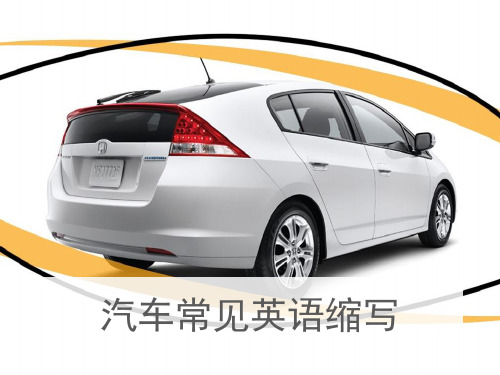
CUV=Car-Based Utility Vehicle
以轿车底盘为设计 平台,融轿车、MPV和 SUV特性为一体的多用途 车,也被称为Crossover。 CUV最初于20世纪末起 源日本,之后在北美、 西欧等地区流行,开始 成为崇尚既有轿车驾驶 感受和操控性,又有多 用途运动车的功能,喜 欢SUV的粗犷外观,同时 也注重燃油经济性与兼 顾良好通过性的这类汽 车用户的最佳选择。
汽车常见英语缩写
一、汽车技术用语的英文缩写:
eg: CVVT、VTT-i等常见的汽车技术,
你知道是什么意思吗?
TSI:
Twinscharger Stratified Injection
双增压(涡轮和机械 增压)分层喷射技术
TSI
是 Turbo-charging-涡轮增压;Super-charging机械增压和Injection-燃油直喷,三个关键特色的首 字母缩写。在涡轮增压的基础上,机械增压填补 了涡轮增压产生迟滞时的动力输出,燃油直喷技 术令发动机对燃料的使用效率提高到新的高度。 在欧洲,搭载双增压发动机的高尔夫GTI1.4TSI在 获得远超2.0L自然吸气时发动机功率的同时获得 了更低的燃油消耗,这真是一台有劲儿的机器, 还很环保。国内引进国产的TSI发动机确切说是FSI 发动机和涡轮增压器的结合。即涡轮增压 (Turbocharger)+FSI.
凯越HRV轿车,取 Healthy(健康)、 Recreational(休 闲)、Vigorous(活 力)之意,和前面 提到的“V”不同, 纯粹玩的是一个概 念。凯越HRV是一 款截至2012年已经 停产的汽车。
SRV=Small Recreation Vehicle
翻译过来 的意思是“小 型休闲车”, 一般指两厢轿 车,比如上海 通用赛欧SRV。
陈黎明自动驾驶汽车量产前面临的3大挑战

本刊特稿SPECIAL FEATURES232020.09 《商用汽车》陈黎明:自动驾驶汽车量产前面临的3大挑战Chen Liming: Three Major Challenges Facing Mass Production of Autonomous VehiclesOn August 13-15, 2020, at the sub-forum of the Forum on 2020 China Auto Forum, "The innovative development of intelligent connected vehicles and the upgrading of industrial ecology", Chen Liming, President of BOSCH Chassis Control System China, delivered a keynote speech, focusing on the 3 major challenges facing the mass production of autonomous vehicles and the 3 essential elements for safe autonomous vehicles.各位来宾,上午好!我来自博世底盘控制系统,负责主/被动安全,以及高级驾驶辅助系统(ADAS)和自动驾驶。
下面和大家分享一下博世关于自动驾驶汽车实现量产之前的一些思考。
自动驾驶汽车已经走过的路为什么我们在讲量产?因为大家在道路上已经看到一些自动驾驶汽车,特别是一些低级自动驾驶或高级辅助自动驾驶(系统),以及一些L3、L4级DEMO(展示/示范)的汽车。
博世从1993年就开始做封闭道路的DEMO,同时也在做高级辅助自动驾驶系统的研发;2013年,博世(自动驾驶汽车)在美国和德国进行公开道路测试,(其他)公司自动驾驶(汽车)研发及测试雨后春笋般展开;2014—2018年,业界L1/L2级辅助驾驶和部分自动驾驶(系统/汽车)迎来大规模量产,接近L3级体验的功能成为趋势,期间博世2017年首先推出了集成式巡航控 本 刊2020年8月13—15日,“2020中国汽车论坛”在上海隆重召开。
Bosch DSA E-Series 8TB (E2700) 商品说明书
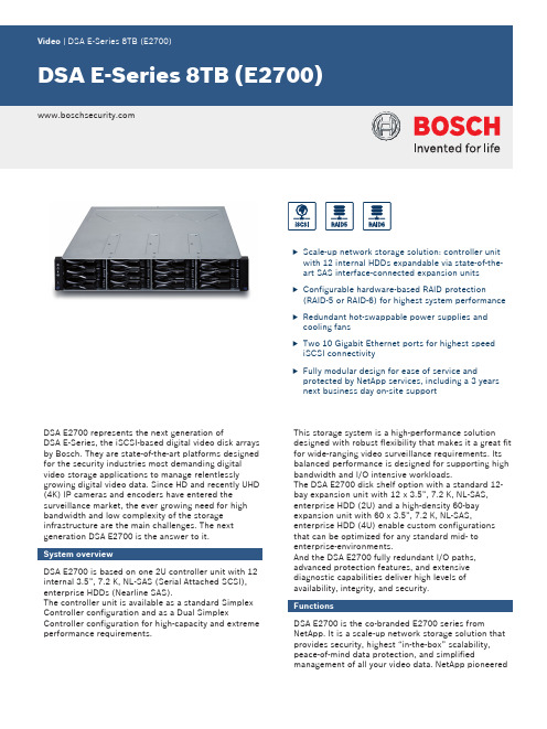
uScale-up network storage solution: controller unit with 12 internal HDDs expandable via state-of-the-art SAS interface-connected expansion units uConfigurable hardware-based RAID protection(RAID‑5 or RAID‑6) for highest system performance uRedundant hot-swappable power supplies and cooling fansuTwo 10 Gigabit Ethernet ports for highest speed iSCSI connectivityuFully modular design for ease of service andprotected by NetApp services, including a 3 years next business day on-site supportDSA E2700 represents the next generation ofDSA E‑Series, the iSCSI-based digital video disk arrays by Bosch. They are state-of-the-art platforms designed for the security industries most demanding digital video storage applications to manage relentlesslygrowing digital video data. Since HD and recently UHD (4K) IP cameras and encoders have entered the surveillance market, the ever growing need for high bandwidth and low complexity of the storage infrastructure are the main challenges. The next generation DSA E2700 is the answer to it.System overviewDSA E2700 is based on one 2U controller unit with 12internal 3.5”, 7.2 K, NL-SAS (Serial Attached SCSI),enterprise HDDs (Nearline SAS).The controller unit is available as a standard Simplex Controller configuration and as a Dual SimplexController configuration for high-capacity and extreme performance requirements.This storage system is a high-performance solution designed with robust flexibility that makes it a great fit for wide-ranging video surveillance requirements. Its balanced performance is designed for supporting high bandwidth and I/O intensive workloads.The DSA E2700 disk shelf option with a standard 12-bay expansion unit with 12 x 3.5”, 7.2 K, NL-SAS,enterprise HDD (2U) and a high-density 60-bay expansion unit with 60 x 3.5”, 7.2 K, NL-SAS,enterprise HDD (4U) enable custom configurations that can be optimized for any standard mid- to enterprise-environments.And the DSA E2700 fully redundant I/O paths,advanced protection features, and extensive diagnostic capabilities deliver high levels of availability, integrity, and security.FunctionsDSA E2700 is the co-branded E2700 series fromNetApp. It is a scale-up network storage solution that provides security, highest “in-the-box” scalability,peace-of-mind data protection, and simplifiedmanagement of all your video data. NetApp pioneeredthe iSCSI protocol years ago and offers with the new E2700 product line a high-end product for the video surveillance market.DSA E2700 in Simplex/Dual Simplex Controller configuration allows connecting up to seven 12-bay expansion units (12 x HDDs per expansion shelf) to one single/dual controller base unit.Note: This is only valid for 12-bay expansion units with two ESM modules.The Dual Simplex Controller configuration allows up to three 60-bay expansion units (60 x HDDs per expansion shelf) connected to one dual controller base unit. Connecting the 60-bay expansion unit to a single controller unit is not supported.It is a fully featured RAID protected disk array which provides RAID‑5 protection for capacity-oriented environments and RAID‑6 protection for availability-oriented environments. The RAID protection is based on a hardware RAID implementation for highest system performance. RAID‑6 is highly recommended if the system will be used with a larger number of disk shelf expansion units.High reliability and availabilityDSA E2700 keeps your data safe and available with redundant hot-swappable power supplies and fans, and protection from double-disk failure and single bit errors during RAID rebuilds with high performance RAID‑6.With over 20 years of storage development experience, DSA E2700 is based on a field-proven design architected to provide high reliability and availability. Its redundant components, automated path failover, and online administration keep organizations productive 24 x 7 x 365.Further high-availability features include:•Automatic drive failover and detection and rebuild ifusing global hot spare drives•Data cache with battery backup and de-stage to flash •SANtricity proactive drive health monitoring identifies problem drives before they create issues MonitoringFull SNMP support with MIB‑II and NetApp custom MIBs supported. In case of component failures SNMP, e-mail alert notifications will be generated. Additionally, an event monitor for sending alert notifications to a central major event log is available. If DSA E2700 is connected to the Internet/Intranet automatically generated AutoSupport messages can be sent. AutoSupport enhances customer service, speeds problem resolution, and helps prevent issues. It automatically sends alerts based on either event-based or time-based (weekly, daily, other) criteria to provide faster and better customer service, keeping your systems up and running longer.ManagementNetApp SANtricity storage management software combines robustness and ease of use. Full-time storage administrators appreciate the extensive configuration flexibility which allows optimal performance tuning and complete control over data placement. Part-time system administrators love the intuitive interface and wizards designed to simplify their tasks. With its dynamic capabilities, SANtricity software supports on-the-fly expansion, reconfiguration, and maintenance without interrupting storage system I/O. The software is available as 32‑bit and 64‑bit Microsoft OS installation package (available on the Bosch product catalogue).Installation/configuration notesInstallable on 32-bit and 64-bit Windows Clients, SANtricity storage management software provides easy central management of all DSA E‑Series arrays available within one network. There is no additional software necessary to be installed on peripheral devices. In addition, the system provides a powerful Command Line Interface (CLI) which is fully remote accessible by SSH (Secure Shell).DSA E‑Series offers per controller a serial console connector and two dedicated Ethernet management ports for management access and 2 x 10 Gigabit Ethernet iSCSI host ports. Each port must be configured with a separate IP address; the two iSCSI host ports are separated access paths to the storage system and represent an individual iSCSI target each. The net capacity available is shown in the followingtable:network (in a 1 Gbit/s network the available network bandwidth is the limiting factor):Network Uplink 10 GbE (RAID-5 / RAID-6)not depend on the number of used ports. The numberof cameras will double by using two ports instead ofone port.NoticeNumber of IP cameras refers to default software configuration (no direct replay mode). Bandwidth data refers to <Recording> / <Replay>.The maximum overall bandwidth of a Dual Simplex Controller system is 2500 Mbps read/write throughput in a 10 GbE uplink network.NoticeDSA E2700 units are only supported by Bosch Firmware 5.60 and later, VRM 3.0 and later, and Configuration Manager 5.32 and later.If total net capacity of the system exceeds 500 TB,Video Recording Manager and Bosch Firmware with large LUN support is required (min. VRM 3.60and Firmware 6.30).NoticeThe next business day on-site service level can only be provided if the respective system has been registered immediately after receipt and installation. Otherwise, service will be provided based on best effort basis.Information about registration details is available in every shipment (registration form) or from the Bosch online product catalog.Next business day services cannot be provided in every country everywhere. For limitations and exceptions see the registration details in the registration form.Dimensions controller unit and 12-bay expansion unitDimensions 60-bay expansion unitFront view controller unit1End Caps (the Left End Cap has the Controller-Drive Tray Summary LEDs)2Drive CanistersRear view Dual Simplex Controller unit1Controller Canister 2Power-Fan CanisterFront view 12-bay expansion unit1End Caps (the Left End Cap has the Drive Tray LEDs)3Right End Cap 2DrivesRear view 12-bay expansion unit1ESM A Canister 3Power-Fan A Canister 2ESM B CanisterFront view 60-bay expansion unit1Drive Drawer 14Drive Drawer 42Drive Drawer 25Drive Drawer 53Drive Drawer 3Rear view 60-bay expansion unit1Fan Canisters 3ESM Canisters 2Power CanistersSimplex Controller 12 x 8 TB (DSA‑N2E7X8‑12AT) /Dual Simplex Controller 12 x 8 TB (DSA‑N2C7X8‑12AT)Electrical requirementsPower ratings (typical operating power)Note: for detailed information please see the latest NetApp E‑SeriesStorage Systems Site Preparation Guide Battery data System hardware specificationsMechanicalDimensions (H x W x D)WeightSpace requirements Environmental TemperatureRelative humidity (non-condensing)Acoustic noise12-bay expansion unit 12 x 8 TB (DSX‑N1D6X8‑12AT)Electrical requirements—expansion unitPower ratings—expansion unitNote: for detailed information please see the latest NetApp E‑Series Storage Systems Site Preparation Guide System hardware specifications—expansion unit Mechanical—expansion unit Dimensions (H x W x D)WeightSpace requirementsEnvironmental—expansion unit TemperatureRelative humidity (non-condensing)Acoustic noise60-bay expansion unit 60 x 8 TB (DSX‑N6D6X8‑60AT)Electrical requirements—expansion unitNote: cables included with the 60-bay expansion systems are designed to be used with 220 - 240 VAC power distribution units Power ratings—expansion unitNote: for detailed information please see the latest NetApp E‑Series Storage Systems Site Preparation Guide System hardware specifications—expansion unitMechanical—expansion unit Dimensions (H x W x D)WeightSpace requirementsEnvironmental—expansion unit TemperatureRelative humidity (non-condensing)Acoustic noiseNotes:General technical information for the RAID systems are provided in the NetApp E‑Series Storage Systems Site Preparation Guide (available at https:///ecm/ecm_download_file/ECMP12366559)NetApp, AutoSupport, and SANtricity are registered trademarks of NetApp, all rights reserved. All data and dimensions are referenced from the NetApp Site Preparation Guide and from the NetApp Website and are subject to change without notice.Ordering informationDSA-N2E7X8-12AT Base unit 12x8TBHigh-performance and high-capacity storage system base unit with iSCSI disk arrays.12 x 8 TB HDDOrder number DSA-N2E7X8-12ATDSA-N2C7X8-12AT Storage system 12x8TB dual control-lerHigh-performance and high-capacity storage system base unit with iSCSI disk arrays, dual controller.12 x 8 TB HDDOrder number DSA-N2C7X8-12ATDSX-N1D6X8-12AT Expansion unit 12x8TBHigh-performance and high-capacity storage expansion unit with iSCSI disk arrays.12 x 8 TB HDDOrder number DSX-N1D6X8-12ATDSX-N6D6X8-60AT Expansion unit 60x8TBHigh-performance and high-capacity storage expansion unit with iSCSI disk arrays.60 x 8 TB HDDOrder number DSX-N6D6X8-60ATAccessoriesDSA-EDTK-800A Hard disk 8TB for DSA E-seriesHard disk storage expansion with a capacity of 8 TB. Order number DSA-EDTK-800ADSX-WDTK-800A Hard disk 8TB DE6600 for DSA E-ser-iesHard disk storage expansion with a capacity of 8 TB. For 60-bay expansion units.Order number DSX-WDTK-800ADSX-NRCK40-INT DSA E-Series Rack Empty, 40U Empty rack with 40U.Order number DSX-NRCK40-INT ServicesSupportEdge Standard extension, 12-bay 4/6/8 TB12-month extension of SupportEdge Standard next business day for DSA E2700 4 TB, 6 TB, or 8 TB based 12-bay controller or expansion units, available for a 4th and a 4th/5th year as a standard.Order number DSA-S2E7X46-SLESupportEdge Standard extension, 60-bay 4/6/8 TB12-month extension of SupportEdge Standard next business day for DSA E2700 4 TB, 6 TB, or 8 TB based 60-bay expansion units, available for a 4th and a 4th/5th year as a standard.Order number DSA-S6D6X46-SLEParts replacement, 12-bay 4/6/8 TB12-month service uplift to SupportEdge Standard: parts replacement within 4 hours for DSA E2700 4 TB, 6 TB, or 8 TB based 12-bay controller or expansion units, available for in-warranty systems only.Order number DSA-S2E7X46-4PRParts replacement, 60-bay 4/6/8 TB12-month service uplift to SupportEdge Standard: parts replacement within 4 hours for DSA E2700 4 TB, 6 TB, or 8 TB based 60-bay expansion units, available for in-warranty systems only.Order number DSA-S6D6X46-4PRNon-returnable disk, 12-bay 4/6/8 TB12-month non-returnable disk option for DSA E27004 TB, 6 TB, or 8 TB based 12-bay controller or expansion units, available for in-warranty systems only. Order number DSA-S2E7X46-NRDNon-returnable disk, 60-bay 4/6/8 TB12-month non-returnable disk option for DSA E27004 TB, 6 TB, or 8 TB based 60-bay expansion units, available for in-warranty systems only.Order number DSA-S6D6X46-NRDRepresented by:Europe, Middle East, Africa:Germany:North America:Asia-Pacific:Bosch Security Systems B.V.P.O. Box 800025600 JB Eindhoven, The Netherlands Phone: + 31 40 2577 284****************************** Bosch Sicherheitssysteme GmbHRobert-Bosch-Ring 585630 GrasbrunnGermanyBosch Security Systems, Inc.130 Perinton ParkwayFairport, New York, 14450, USAPhone: +1 800 289 0096Fax: +1 585 223 9180*******************.comRobert Bosch (SEA) Pte Ltd, Security Systems11 Bishan Street 21Singapore 573943Phone: +65 6571 2808Fax: +65 6571 2699*****************************© Bosch Security Systems 2017 | Data subject to change without notice 24616659979 | en, V2, 17. Aug 2017。
人工智能英语(基础级)

Hello, everyone. Now let’s talk about one of the most popular applications of AI, self-driving vehicles.大家好,现在我们来谈一谈人工智能最热门的应用之一,自动驾驶汽车。
In this period, we’ll learn some basic information about self-driving vehicles.在这一节,我们将学习一些关于自动驾驶汽车的基本信息。
I’ll introduce to you the definition of self-driving vehicles, a brief history, six layers of autonomy, and operating principles.我将向你们介绍自动驾驶汽车的定义,简要的历史,六个级别的自主性,以及操作原理。
Firstly, definition.首先是定义。
According to Wikipedia, a self-driving vehicle is a vehicle that is capable of sensing its environment and moving with little or no human input.根据维基百科的说法,自动驾驶汽车是一种能够感知环境并在无需或仅需少量人力投入的情况下行驶的汽车。
That means self-driving vehicles are cars or trucks in which human drivers are seldom or never required to take control to safely operate the vehicle.这意味着,自动驾驶汽车是一种汽车或卡车,司机很少或从未被要求控制汽车的安全运行。
Bosch Smart Home Controller 用户手册说明书
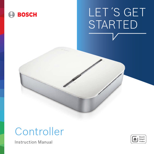
Controller23Dear customer,Congratulations on purchasing your BoschSmart Home Controller. It is the basic compo-nent for making your home smarter.With the Bosch Smart Home Controller, you will be able to network all of your Bosch Smart Home products digitally. And, thanks to the Bosch Smart Home App, you will be able to control them conveniently from anywhere. For greater convenience, reliability and energy savings.We hope you enjoy your new product. Yours, the Bosch Smart Home TeamTABLE OF CONTENTS1.0 PRODUCT DESCRIPTION ...............................41.1 Intended use 42.0 IN THE BOX .....................................................53.0 WARNING NOTICES ........................................63.1 Explanation of symbols 63.2 Safety instructions 64.0 INDICATORS AND CONTROLS ........................74.1 Product overview 75.0 INSTALLATION AND SETUP .............................85.1 Downloading the app 85.2 Installing the controller 95.3 Configuring the controller 106.0 FIXING ..........................................................126.1 Wall mounting 125.4 Adding further devices 127.0 MAINTENANCE AND CARE ...........................138.0 PRODUCT DETAILS .......................................148.1 Technical data 148.2 Declaration of conformity 158.3 Faults in radio operation 158.4 Open-Source-Software 158.5 Environmental protection and disposal 159.0 FURTHER INFORMATION (15)1.0 PRODUCT DESCRIPTIONWith the Bosch Smart Home Controller, you will be able to network all of your Bosch Smart Home components digitally. And, thanks to the Bosch Smart Home App, you will be able to control them conveniently from anywhere. Your controller is updated automatically so that it remains up to date at all times. All system data is saved locally in the device, thus ensuring that your data remains secure.1.1 Intended useThe product may only be used together with original Bosch Smart Home components, and is for indoor use only▶ F ollow the safety instructions and the direc-tions in this manual and the Bosch Smart Home App to ensure that the product is set up correctly▶ P lease note the details in the Technical Data section (see p. 14)▶ A void installing in areas prone to high amounts of dust, direct sunshine or heatD o not modify the product in any way. Anyother use is considered unintended use. Wewill not assume liability for any resultingdamage.45T o operate the controller and, therefore,network all Bosch Smart Home products, youwill need the app, an internet connection anda standard WLAN router with a free LAN port.2.0 IN THE BOXController Wall mount 2 plugs,2 screwsPower cable Network cable3.0 WARNING NOTICES3.1 Explanation of symbolsW arning.This alerts you to danger.I nfo.Indicates important information.3.2 Safety instructionsF ire risk.There is a risk of fire if the product isused with a different power cable to thatsupplied.▶ O nly use the product with the originalpower cable.T he device may only be connected to aneasily accessible mains socket. In case ofdanger, the mains plug must be pulled outof the socket.Due to external circumstances such as a breakin radio communication with the Smart Home Controller, it cannot always be guaranteed during remote or automated appliance control that commands are actually executed or the correct appliance status is displayed in the app and on other Smart Home display devices (e.g. a Twist). This may result in damage to property and/or injury.In this case:▶ P lease ensure as far as possible that no-one is at risk during remote operation or automated control.▶ P lease exercise particular caution when setting up or adjusting a remote or automated control and regularly check the desired operation mode.674.0 INDICATORS AND CONTROLS4.1 Product overviewFront sideRear side85.0 INSTALLATION AND SETUP5.1 Downloading the appB efore you startMake sure that you download the BoschSmart Home App. You will need it for theentire installation, configuration and control.F or assistance with installing your BoschSmart Home Controller, you may also referto the explanatory video on our website:/installation W LAN access requiredTo set up the controller, you must have theBosch Smart Home App on your mobiledevices and be within range of the WLANnetwork router.9www1)After initialization, the cloud LED flashes when data is being exchanged via the tunnel connection.Insert the network cable into the controller and into a free LAN port on your WLAN router. Now use the power cable to connect the controller to the plug socket. After the device starts, the LEDs show the initialization status using flash codes (see table).W hen you connect the controller to the internet for the first time, it will automat-ically search for software updates. If an update is required, it will be downloaded automatically by the controller and installed. This process may take up to 30 minutes. con-troller setup cannot begin until this process is complete.10The controller must be the first device inyour system that you connect with the app.A fterwards, you can connect additional BoschSmart Home products and expand your system.Start the app and wait until it has detected thecontroller.F rom this point, the app guides you throughthe installation process. You will find a briefdescription in the following pages of thisinstruction manual.The app will prompt you to scan the QR code onthe product. You will find the QR code on therear side of the Plug.11The following steps in the app are:▶ R egistrationRegistration: set your system password you want to register with your smart home control-ler. You will need the system password later if you want to integrate more mobile devices into your Smart Home system, or to reset the Smart Home Controller to factory settings.)▶ R emote access configurationThe app will inform you when the controller is completely set up. All controller LEDs will also light up white.Next, the app will prompt you to press and hold the function button on the controller for approxi-mately 3 seconds.126.0 FIXINGThe controller can be used lying flat or mounted on the wall.6.1 Wall mountingW hen choosing a mounting location and when drilling, pay attention to potential electrical lines and/or supply lines that could be behind the wall.To mount your controller on the wall, use the wall mount provided. The plugs and screws required are also included in the box.5.4 Adding further devicesOnce the controller has been completelyinstalled, you can add further products to your Bosch Smart Home network through the app. To do this, follow the instruction manual for the relevant device.13▶ H old the wall mount at the required location on your wall, and mark the positions for the drill holes ▶ D rill the holes and place the plugs in the holes ▶ F it the wall mount and screw it tight ▶ N ow attach the controller to the wall mount so that you hear it click in place7.0 MAINTENANCE AND CAREThe product is maintenance-free. Repairsshould only be performed by qualified persons. Clean the product with a soft clean dry and lint-free cloth. Do not use cleaning agents containing solvents.I ncorrect handling (see notes on intended use) or non-observance of hazard warnings may compromise the protection afforded by the device.8.0 PRODUCT DETAILS8.1 Technical dataDevice type name Home Controller AAArtikelnummer8-750-000-163Power input Typical: 400 mAMax.: 1,2 AReceiver category SRD category 2Radio frequency868.3 MHz/869.525 MHz/2.4 GHzMax. transmission power10 mWRadio range in free-field conditions> 100 mDuty Cycle At 868,3 MHz < 1 % per hAt 869,525 MHz < 10 % per h Connections Power supply, USB, LAN (Ethernet, RJ45) Protection class IP30Ambient temperature+5 °C to +40 °CHumidity15 % to 85 %Software class Class ADimensions (W × H × D)135 mm x 120 mm x 35 mmWeight190 g148.2 Declaration of conformityHereby, Robert Bosch Smart Home GmbH declares that the radio equipment type Bosch Smart Home Controller is in compliance with Directive 2014/53/EU. The full text of the EU declaration of conformity is available at the following internet address: /EU-declarations-of-conformity8.3 Faults in radio operationFaults in radio operation (e.g. dueto electric motors or defective electrical devices) cannot be ruled out. The radio range inside buildings may differ greatly from the radio range in free-field conditions. Apart from the trans-mission power and the receiver characteristics, environmental influences such as humidity and structural characteristics may also influence radio operation.8.4 Open-Source-SoftwareBosch Smart Home relies on open-source software in order to control the products. You have two means of obtaining the comprehensive license information:▶D irectly from the controller: Insert an empty USB stick in the port on the rear side of the device. The licence information, as well as other product information, will be saved to the stick automatically.▶O nline at /open-source software 8.5 Environmental protection and disposal Electrical and electronic equipment that is nolonger usable must be separated from otherwaste and recycled in an environmentally friendly manner (European Directive on waste electri-cal and electronic equipment). To dispose of electrical and electronic equipment, use yourcountry-specific return and collection systems.9.0 FURTHER INFORMATIONYou can find more detailed informa t ion on oper-ating and maintaining the controller in the online FAQs at /faqYou will also find all contact details on the rearside of this document.S ale and transferBefore you transfer or sell your device,delete your personal information. To do this,reset the device to its factory settings (seeonline FAQs).15Robert Bosch Smart Home GmbH Schockenriedstraße 1770565 Stuttgart, GermanyFree customer helpline00800 8437 6278** F ree, however, depending on the opera-tor, charges may apply.Mon–Fri 7:00 am – 8:00 pmSat/Sun 8:00 am – 6:00 pm***************************。
BOSCH-ESP
5
ESP是如何工作的
ESP首先通过方向盘转角传感器及各车轮转速 传感器识别驾驶员转弯方向(驾驶员意愿) a图
ESP通过横摆角速度传感器(英文原称为yaw rate sensor ),识别车辆绕垂直于地面轴线 方向的旋转角度及侧向加速度传感器识别车 辆实际运动方向 b图
EBD 系统是防止ABS起作用以前, 或者由于特定的故障导致ABS失 效后,后轮出现过度制动。
ESP- Electronic Stability Programe
通过有选择性的分缸制动及发动 机管理系统干预,防止车辆滑移。
EDL-Electronic Differential Lock
两驱动轮在附着系数不同的路面 上,出现单侧车轮打滑时,制动 打滑车轮。
Dynamic Stability Control (DSC)-BMW Vehicle Stability Control (VSC)-Toyota Vehicle Stability Assist (VSA)-Honda Automatic Stability Management System Driving Dynamic Control ESP是一个主动安全系统。它是建立在其它牵引控制系统 之上的一个非独立的系统。
液压单元 车辆 司机
电子控制单元
传动器 发动机管理系统
油门踏板 警告信息系统
26
优先原则 ESP与其它动力控制系统的关系(优先原则) TCS逻辑覆盖ESP逻辑(只发生在驱动轮)即:选择较低的制动压力施 加在车轮上。与TCS直接介入有所不同的是,此时动力源来自ESP压力 调节器,否则将破坏液压系统。
绪论

绪论随着汽车工业的快速发展,计算机在汽车上的应用越来越广泛,汽车底盘也发生了重大的变革,他改变了汽车传统的机械装置,并增加了许多新的功能,是汽车的驾驶更加简单方便,乘坐更为舒适安全。
汽车底盘电子控制主要包括:电控自动变速器、防抱死系统、驱动防滑系统、电子稳定程序控制系统、电控悬架系统、专项控制系统等。
一、自动变速器自20世纪30、40年代起,人们不遗余力的发展自动变速器(Automatic Transmission,AT)到20世纪70年代,美国每年生产的600万~800万的轿车中,AT的装备率超过了90%,这一趋势也很快波及了欧州、日本等汽车大国,竟相来发自己的自动变速其产品。
在日本20世纪80年代后期对AT的需求超过了65%,并且人在增加,AT不仅在轿车上的得到了最广泛的利用,同样在公共汽车、矿用汽车以及越野军用车辆中也迅速得到了应用。
装用自动变速器车辆的比例越来越高,各大汽车公司都已建立了大规模生产AT的准也工业化。
20世纪80年代,随着微电子技术的迅速发展,机电一体化技术进入汽车领域,推动了汽车变速装置的重大变革。
三种传动装置均出现了电子化的趋势。
1.液力自动变速器(AT)把原有液压控制完成的功能改由微处理器来完成,实现了由AT向EAT(Electranic con-trolled AT)转变,并减少了结构复杂和制造技术的要求吗,降低了成本,提高了产品的适应性。
2.手动式机械变速器(Manual Trasmission,MT)借助于微机控制技术,他正在演变成电子计算机控制的机械式的自动控制变速器(EMT E-lectronnic-controlled Mechnical Trasmisstion 或AMT___Automated Mechnical Transmission ),从而克服了手动操作的种种弊端。
双离合自动变速器式是基于手动变速器发展而来的,其工作原理是通过将变速器档位按奇偶分开布置,分别与两个变速器链接,通过切换两个离合器的状态,就可以完成换挡动作。
汽车电子技术专业介绍
1.2我国汽车电子产业发展特点
普及电控电喷系统,提高动力系统效率, 可以看出所有发动机已采用了电子技术, 厂商也正在普及和提高:电控高压共轨 柴油机正大量研究,电力电子模块混合 动力驱动系统成驱动主力,氢燃料电池 混合动力汽车商业化取得新进展。
1.2我国汽车电子产业发展特点
线控或驱动系统迅速发展,线控转向、线控制 动正加紧研究,线控将取代机械系统,汽车 底盘将发生革命性变化。 ITS正迅速兴起,包括汽车的智能化、公路的 自动化和导航系统等。 综合控制成为汽车电子信息技术发展趋势,包 括动力传动系统、底盘与安全系统、车身与 防盗系统等,远程信息处理系统将使蓝牙技 术广泛应用于汽车,汽车智能化将不断升级。
主要内容
汽车电子技术的发展及典型应用 汽车网络通信技术概述
1.1汽车电子控制技术发展概况
20世纪60年代:燃油喷射、速度控制、 制动防抱死等方面的电子控制装置,由晶 体管分立元件组成; 20世纪70年代初期:集成电路的应用; 1976年,美国通用公司首次将微处理 器应用于汽车发动机点火控制; 20世纪90年代,信息技术在汽车上得 到发展。电子化仪表、电子地图和GPS系统。
主要车载网络的基本情况
车载网络的名称 CAN(Controller Area Network) VAN(Vehicle Area Network) J1850 LIN(Local Interconnect Network) TTP/C(Time Triggered Protocol by CAN) 概 要 车身/动力传动系统控制用 LAN 协议,可能成为世界标准 车身系统控制用 LAN 协议,以 法国为中心 车身系统控制用 LAN 协议,以 美国为中心 车身系统控制用 LAN 协议,低 端子系统专用 重视安全, 按用途分类的控制用 LAN 协议,通用时分多路复用 通信速度 /(b/s) 1M 1M 41.6 K 20 K 2M 25 M 组织/推广单位 Robert Bosch 公司 ISO ISO Ford Motor 公司 LIN 协会 TIT 公司
博世汽车部件(苏州)有限公司

博世汽车部件(苏州)有限公司博世这个名字始终与汽车密不可分。
从发明世界上第一个火花塞,推出柴油、汽油喷射系统及防抱死制动系统ABS,到推出电子稳定系统ESP,高压共轨柴油直喷系统CRS及汽油直喷系统DI-Motronic,均在向世人展示:博世已成为领先技术、高尚品质的象征!罗伯特.博世公司,总部位于德国斯图加特,是全球500强企业之一。
其汽车技术部,拥有超过12万员工,业务遍及世界130多个国家及地区,是世界最大的独立汽车零部件供应商之一。
产品被世界主要汽车制造厂商指定为原厂配件。
博世在汽车零部件各个方面的研发及生产水平均居于世界领先地位,在汽车行业的历史上建立了一个又一个的里程碑,博世以其专业的技术和一贯的创新精神而著称于世。
自进入中国市场以来,博世就以卓越的产品性能及超前的环保理念赢得了国内各大汽车厂商的认可。
继柴油喷射系统在行业中取得巨大的成功之后,博世汽车的底盘系统、能源与车身系统、汽车多媒体系统、汽车电子系统和ATMO设备项目等部门也相继进驻博世(苏州)公司,现已逐步运作投产,博世汽车部件(苏州)有限公司将会成为博世汽车零部件生产及匹配中心。
随着公司规模,业务的不断扩大,我们着力建立一支高技术,高素质的团队以适应新形势。
我们欢迎各地英才的加盟,与博世一起,与中国汽车工业一起发展和进步。
博世将为员工提供更好的职业前景和更优良的培训机会,我们在此诚邀您的加盟。
汽车多媒体系统 (Car Multimedia Division)Blaupunkt is a market leader in the field of automotive communications. The company offers a real “advantage for your car” and more driving pleasure through innovation and design-oriented systems that provide substantial customer benefits.It truly is “the advantage in your car“.作为汽车多媒体领域的市场先锋,蓝宝凭借着创新精神和卓越的设计能力,让您感受“发烧级汽车音响”,创造客户利益。
布斯奇建筑集成系统(BIS)安全与安全文件说明书

party system: Facility Management (planning and costs), ERP (SAP, Time & Attendance), SCADA
Workstation
Workstation
Workstation
Workstation
fire & life safety
▶ Easily access post-event reporting and forensic analysis to help in future process optimization
▶ Protect your investment by being open, flexible and always backward compatible for maximum return on investment
MS-GB-en-01_F01U560768_01.indd 1-2
When designing comprehensive security and safety systems, both planners and building operators often choose to mix and match fire protection, public address, access control, video surveillance and management systems from multiple vendors.
▶ Connect and integrate an extensive range of Bosch and 3rd party security and safety products for maximum design flexibility
Bosch 电子式洗碗机说明书

Accessories: To purchase Bosch accessories, cleaners & parts please visit /us/store or call 1-800-944-2904 (Mon to Fri 5 am to 6 pm PST, Sat 6 am to 3 pm PST).SHEM78ZH5N Stainless SteelPatented CrystalDry™ technology transforms moisture into heat to get dishes, including plastics, 60% drier.142 dBA: dishwasher runs quietly so your kitchen conversations aren’t interrupted.Home Connect™ delivers peace of mind with remote start, check cycle status, remote diagnostics, and automated tab replenishment through Amazon Dash.The Flexible 3rd Rack with fold down sides adds 30% more 2 loading area, perfect for utensils and ramekins.The AquaStop® leakprotection system contains leaks through a precisely engineered system. If a leak occurs, the system contains it by shutting down operation andpumping out water. So you have the ultimate peace of mind whether you areaway or at home.1Based on aggregate average drying performance of Bosch Dishwashers with CrystalDry on combined household load including plastics, glass, steel, andporcelain as compared to Bosch Dishwashers with PureDry®. Drying performance may vary by dish type.2Compared to a Bosch dishwasher with 2 racks.3Certification to NSF/ANSI Standard 184 for residential dishwashers. 4September 2020 running production change to remove adhesive routing clips for power cord. These clips and the edge protector are now included in the dishwasher accessory kit #SMZEPCC1UC.Accessories: To purchase Bosch accessories, cleaners & parts please visit /us/store or call 1-800-944-2904 (Mon to Fri 5 am to 6 pm PST, Sat 6 am to 3 pm PST).Installation DetailsJunction box accessoryInstallation DetailsAccessories: To purchase Bosch accessories, cleaners & parts please visit /us/store or call 1-800-944-2904 (Mon to Fri 5 am to 6 pm PST, Sat 6 am to 3 pm PST).。
autoshift_gearbox

Integrating of the Auto Shift Gearbox April 9, 1999 with the electrical machineDr. Robert FischerGunter HirtLuK Getriebe-Systeme, BühlIntroductionAgainst all predictions, manual transmissions still have in Europe a market share of more than 80%. This can be attributed to the high efficiency and the small space required for installation together with low weight and low cost.In the meantime, there are indications that the manual shift transmission can be successfully automated and thus additional advantages can be gained at very little expense.The basis was the automatic clutch, as provided by LuK and Bosch for the Mercedes-Benz A-class. In the meantime, we have the first Auto Shift Gearbox (ASG), which is based on a manual shift transmission [1], [2]. Eliminating the interruption of the tractive force during shifts promises major potential for improvement.As shown in other lectures, not only can the starter generator fulfill the demands of future on-board electrical systems, but major energy-related advantages can also be achieved. According to calculations by LuK, energy savings as high as approx. 20% can be achieved in comparison to the currently available manual shift transmission, thanks to the start-stop automatic system, and the recovery of braking and coast energy [3] to [7].By combining the ASG and the starter generator in an intelligent manner, LuK is aiming to achieve more than just the sum of the advantages of these systems –the goal is also to eliminate the interruption in the tractive force. LuK calls such a transmission Electric Shift Gearbox (ESG).1Arrangements of the starter generator in the ASGFigure 1 depicts an overview of the different possible arrangements for the electrical machine in the drive train with a manual transmission.Figure 1:Arrangements of the starter generator in the drive trainIn the first possibility, the starter generator can be attached to the crankshaft (Figure 1a). With this arrangement, starting and generating are possible. In principle, recovery is also possible, however, it does not utilize the full potential of the starter generator, since the internal combustion engine must always be rotated.The electrical machine can be placed onto the transmission-input shaft (Figure 1b). To do so provides the advantage that the electrical machine can be disengaged from the engine, therefore allowing the full potential for recovery. In comparison to the previously mentioned solutions that were attached to the engine side, the potential saving is approx. 10% higher.2The internal combustion engine can be started either with an engaged clutch directly or with an impulse start, where the starter generator is accelerated first and the clutch is subsequently engaged. Thus, the electrical machine does not have to deliver the maximum drag torque at low temperatures, what allows the use of a smaller electrical machine.For this solution it is necessary to automate the manual transmission, since to start the vehicle, it must be taken out of gear and the clutch has to be engaged; and to recover, the vehicle has to be put in gear and the clutch has to be disengaged.By keeping the electrical machine on the input shaft, the weak point of the ASG –an interruption of the tractive force during the shifting process – is retained.To change this, the electrical machine must impinge on the power take-off train, (Figure 1c). In this case, recovery is also possible. Here, too, a connection with an automated clutch or an Auto Shift Gearbox is required. With this arrangement, however, the internal combustion engine can no longer be started with the electrical machine, and a generating process is possible only during driving.In order to fulfill all requirements, i.e., starting, generating, recovering and power shifting, the electrical machine must be able to either affect the input shaft or the power take-off (Figure 1d).Therefore, the desired consumption advantages and starter generator function can only be achieved if the electrical machine can affect the transmission input. Therefore, we will concentrate only on variations 1b and 1d.3Shifting gears using individual synchronizationsHaving the electrical machine on the transmission input shaft, the challenge lies in the shifting process. To illustrate this, we will first describe the shifting process of an Auto Shift Gearbox (ASG).On the right side, Figure 2 depicts (using symbols) the drive train with the manual shifting transmission, i.e., the ASG. The clutch connects the internal combustion engine and the input shaft. Between the input shaft and the output shaft two toothed gear pairs act with different ratios and a shiftable dog clutch. A single synchronization affects each dog clutch. A tire at the output shaft symbolizes the vehicle mass.Figure 2:Up-shifting the ASG using individual synchronizationIn the top diagram in figure 2, the speed characteristics of engine and the input shaft are depicted over time; and in the bottom diagram, the corresponding torque at the drive shaft.4What happens during the shifting of the gears? First, a look at the process without the starter generator.In order to release the dog clutch of the old gear, the torque at the transmission input is reduced to zero (point-in-time A). To achieve this, the engine torque is decreased and the start-up clutch is disengaged, which has a direct effect on the output. The transmission input shaft and the internal combustion engine are decelerated very slowly. By synchronizing the process at the dog clutch of the new gear, the gear input shaft is very quickly brought to the speed level of the subsequent gear via the synchronization on the dog clutch of the new gear (range from B to C). Then the new dog clutch can be engaged (Point D). Finally, with the help of the start-up clutch, the speed is synchronized between the engine and the transmission input shaft. Afterwards the torque of the new gear acts on the transmission. The thin lines depict the speed curves that would result without adjusting by synchronizing and re-engaging the clutch.If the starter generator is connected with the input shaft, then not only the rotating mass of the input shaft, but also that of the electrical machine must be accelerated during the synchronization phase (range from Point B to C). This would lengthen the phase and would stress the synchromesh more. To give support, the electrical machine could receive power. The power requirements are very high however, if the vehicle is to be shifted within the same time-frame as when no additional rotating mass is present. A few attempts to integrate the starter generator into the ASG were not successful due to this problem. Therefore, we are looking for a synchronization that takes into account the mass of the electrical machine. The following two sections show an approach and a solution.5Synchronization using the engine brake against the housing.The principle introduced here is already being currently used in trucks (Figure 3).Figure 3:Synchronization using the engine brake against the housing Synchronization of the speeds of the transmission input shaft, the internal combustion engine and the electrical machine is achieved by a powerful brake acting against the housing.Therefore, it is not necessary to synchronize the individual dog clutches. An interruption in the tractive force, however, cannot be avoided even during this kind of synchronization.6Synchronization using the engine brake against the power take-offIn the above principle of the engine brake, the torque is supported at the housing. During the braking process, the kinetic energy of the internal combustion engine and the electrical machine is transformed into heat and is lost to the drive.Figure 4:Synchronization using the engine brake against the power take-off It is preferable to deliver this torque to the drive train, using a power shifting clutch and thus to transfer portions of the kinetic energy of the internal combustion engine and the electrical machine during the shifting process to the vehicle (Figure 4). This is the basic principle of the Electric Shift Gearbox (ESG).7Here, the power shift clutch fulfills two functions:•Synchronizing the transmission input shaft, internal combustion engine and electrical machine•Avoiding the interruption in the tractive force by delivering the torque to the drive trainIn comparison to the ASG, using this principle to adjust the speed eliminates the delay times that occur between disengaging the dog clutch and beginning the synchronization process, as well as between the completion of the synchronization process and the re-engagement. The gear shifting elements move simultaneously in the interlocking phase and independently of the synchronization process by the power shift clutch. The gradient of the transmission input shaft speed during the synchronization process may now be less than that of the ASG (Figure 2), without it lengthening the time it takes to shift gears. This simplifies the demands on the electrical machine.The thin line in Figure 4 again compares the speed curve, as it would be without synchronization by the power shift clutch.8The Electric Shift Gearbox – ESGDesign of the ESGFigure 5 depicts how, in principle, an ESG could be designed.Figure 5:ESG designSynchronizers are eliminated, and now an additional power shift clutch is added to the start-up clutch. This power shift clutch connects the input shaft with the output shaft via an auxiliary gear pair – here depicted for the sixth gear. The demands made on the power shift clutch regarding torque and performance are similar to those made on a start-up clutch. In addition to being used for power shifting, this clutch can also be used as a locking mechanism for parking, without any additional expense! To do this, the power shift clutch is engaged after a gear has been selected – this puts the drive train into a torque-lock condition.9As mentioned above, in order to transmit the inertia effect and the torque of the internal combustion engine to the transmission and thus via the power shift clutch to the vehicle, the start-up clutch remains engaged during the shifting processes. This means that during the start-up only the start-up clutch is used and when the gears are shifted, only the power shift clutch is used. This is the basis of the idea to operate these two clutches with a common actuator and to design them as a combi clutch (Figure 6).Figure 6:ESG with one actuator for the start-up and power shift clutch10The corresponding characteristic curves for torque are depicted in Figure 7.Figure 7:The torques of the start-up clutch and power shift clutch versus actuator travelIf the actuator is located at Point A, then both clutches are disengaged. On the way from Point A to Point B the start-up clutch will be engaged and the vehicle starts to move. If the actor is at Point B, it can either move left and disengage the start-up clutch and it can realize the torque follow up strategy or it can move to the right (in the direction of Point C) and then initiate the shifting process by activating the power shift clutch, whereby the start-up clutch remains completely engaged.11Cost comparison of ESG to ASGAs many components as possible were used from the ASG during the design of the ESG. They have the same number of the following components:•Start-up clutch•Clutch actuator•Shifting actuators•Interior shiftingmechanism•Input shaft•Output shaft•Gear sets•Dog clutches•Housing•Release bearingNo additional actuator is required, despite power shifting and the electrical machine. In addition, the following components are required:•Connection to the transmission •Electrical machine / Electronics•Larger battery•Wiring•Power shift clutchTo compensate, the following components are eliminated:•Synchronizers•Generator•Starter•Belt drive12ESG system requirementsControlsWith ESG, triggering the system, in particular the clutches, is a considerable challenge.In order to fulfill the synchronization function, the power shift clutch, the internal combustion engine and the electrical machine must be controlled in a coordinated manner. In addition to the shifting strategies the additional functions of the electrical equipment (starting, supplying power to the on-board net) must be guaranteed.The power shift clutch slips during the shifting phase and thus dominates the power torque. This requires very sensitive control.Another challenge lies in disengaging and engaging the dog clutches. During the disengagement process the precise point in time must be found where the dog clutch is torque-free. During the engagement process the speed must be synchronized, however, at the same time the speed gradients should be as equally high as possible.Comprehensive total system knowledge is necessary to coordinate engine, clutches and transmission. LuK already has gained expertise in this area from developing the ASG.Power shift clutch designHigh friction performance and good modulation capability is demanded from the start-up clutch as well as from the power shift clutch. The energy savings could be even higher than that of the start-up clutch, which would make wear-adjustment a sensible idea. If the clutches are designed as a combi clutch – start-up clutch and power shift clutch in one module – then this poses a particularly big challenge. In addition, both clutches must be reduced in force in order to use a small clutch actuator. Certainly that would be the right task for the clutch development departments at LuK.13On the road to ESG:The Uninterrupted Shifted Gearbox – USGIn the revolution of the vehicle on-board system, with the EMST introduced here, we can offer a totally optimized transmission system.In preparation, partial aspects of this technology can already be introduced without much additional expense. The introduced concept of the power shift clutch can already be used as an independent alternative to the manual transmission, i.e., the ASG, without integrating the electrical machine. LuK calls this system the Uninterrupted Shifted Gearbox (USG).Design of an USGFigure 8 depicts the design of an USG with a combination clutch that is activated with only one actuator.Figure 8:Design of the USG1415LuK took the first step with the prototype illustrated in Figure 9. Here, the power shift clutch is attached to the fifth gear in an existing ASG. Only in the nextdevelopment step are the two clutches to be united into a combination clutch.Figure 9:LuK prototype for the USGCost comparison of the USG to the ASGASG and USG have the same number of the following components:•Start-up clutch•Clutch actuator•Shifting actuators•Internal shiftingmechanism•Input shaft•Output shaft•Gear sets•Dog clutches•Housing•Release bearingDespite increasing the ASG function to that of the USG, no additional actuator is required. Only one additional component is required, whereby it can be made cost-efficiently by integrating it into the existing clutch:•Power shift clutchThe following components are eliminated:•SynchronizersThis comparison shows that despite the advantages, the USG does not have to be more costly than the ASG. Upgrading the USG to an ESG is possible without major effort.We see an additional advantage by having the transmission manufacturers retaining the existing investments, which is made possible by the majority of the parts being the same.16Summary of the characteristicsIn many ways, the ASG is the best in its class. Highest efficiency and lowest manufacturing costs, combined with lowest weight in the smallest space, which lead to lowest consumption and promise a long life for the ASG and thus the investments made in the manual transmissions (Figure 10).Figure 10:Characteristics of ASG, USG and ESGFor the USG, all these advantages are preserved. It offers additional functions, however, such as power shift and parking lock-up at no additional cost. Therefore, the USG is a stand alone system.The USG, in turn, is the optimum basis for expansion with the starter generator to the ESG. The ESG is a turnkey concept that retains all the advantages of the ASG and USG and that fully utilizes the potential offered by the starter generator at start-stop and with recovery. All the additional functions of the starter generator, such as energy conversion, higher on-board network, performance and boosting are possible.17In the ESG the electrical machine supports the power shift clutch of the USG, making the shifting process even more comfortable and quicker (see Figure 11).Figure 11:Vehicle acceleration during shifting with ASG, USG and ESGSystem classificationIn this lecture we dealt with the Uninterrupted Shifted Gearbox (USG) and the Electric Shift Gearbox (ESG) as a further development of the Auto Shift Gearbox (ASG). How do these systems relate to each other and how do they relate in comparison to other transmission systems?In Figure 12 we attempted to depict a cost-benefit evaluation, whereby the good comfort and good performance level represent the benefit for the client.18ESG= Electric Shift Gearbox EVT= Electrically variable transmissionUSG= Uninterrupted Shifted Gearbox CVT= Continuously variable transmissionASG= Auto Shift Gearbox AT= Automatic transmissionECM= Electronic clutch managementMT= Manual transmissionFigure 12:Cost-benefit analysis of various drive train automatic systems Currently, the manual transmission, the most cost-efficient transmission available today, is taken as the basis. The other known reliable cornerstone is represented by the automatic transmission (AT), with greater benefits, but also at higher costs. According to our estimates, the electronic clutch management (ECM) is at about one-third between the two systems mentioned above with regard to the benefits and costs.With the ASG the benefit increases markedly in relation to the ECM, without markedly higher costs.19The USG is most likely as reasonable in cost as the ASG. However, the comfort level continues to increase, since the interruption in the tractive force is eliminated. LuK estimates the benefit of the USG to be equal to that of the automatic transmission, the focus being, however, on other classes of vehicles. With the USG not quite approaching the shifting comfort of the automatic transmission, the consumption nevertheless is much lower.The ESG is the further development of the USG. The additional costs for the electrical machine and the performance electronics may not be assigned exclusively to the transmission, since the many advantages of a starter generator must be evaluated, in part, independently of the drive train. We see the major advantage in the potential for savings in fuel consumption.The CVT costs approximately as much as an automatic transmission, however, it offers decidedly more comfort.If comfort is the focal point during the development, then successors have been considered for the automatic transmission and the CVT. Systems will be used as have been introduced by, amongst others, Prof. Tenberge in his lecture [8]. As can be seen in Figure 12, however, this addresses a completely different market segment than ESG does.ASG, USG and ESG are further developments of the manual transmission. LuK is working on it!20Literature[1]Fischer, R.; Berger, R.: Automatisierung von Schaltgetrieben, [Auto Shift Gearboxes] 6. LuKColloquium 1998[2]Berger, R.; Fischer, R.; Salecker, M.: Von der Automatisierten Kupplung zum AutomatisiertenSchaltgetriebe [From the automated clutch to the Auto Shift Gearbox]; VDI-Bericht [VDI Report] 1393[3]Reik, W.: Startergenerator im Antriebstrang [Starter generator in the drive train], LuK-Fachtagung E-Maschine im A ntriebsstrang [LuK conference of experts on the electrical machine in the drive train] 1999[4]Boll, W.; Antony P.: Der Parallel-Hybridantrieb von Mercedes-Benz [The parallel hybrid driveby Mercedes-Benz]; VDI-Bericht [VDI Report] 1225[5]Kerschl, S.; Höhn, B.; Pflaum, H.: Einsparpotentiale des Autarken Hybrid-Fahrzeugs [Thesavings potential in autonomous hybrid vehicles], VDI-Bericht [VDI Report] 1459[6]Buschhaus, W.; Jaura, A.; Tamor, M: P2000 LSR – Fords Systematic and Integrated HEVDevelopment Program, VDI-Bericht [VDI Report] 1459[7]Dietrich P., Eberle M.: Betriebsverhalten des ETH-Hybrid III Antriebes auf dem dynamischenPrüfstand und im Fahrzeug, [Driving behavior of the ETH-Hybrid III drive on the dynamic testing range and in the vehicle], VDI-Bericht [VDI Report] 1459[8]Tenberge, P.: Automatisiertes Fahrzeuggetriebe mit elektrischener Regelungà Hybridgetriebe, [Automated vehicle manual shift transmissions with electronic controls àhybrid shift transmissions] LuK-Fachtagung E-Maschine im Antriebsstrang [LuK conference of experts on the electrical machine in the drive train] 199921。
SCODE-ANALYZER工具及应用案例分享
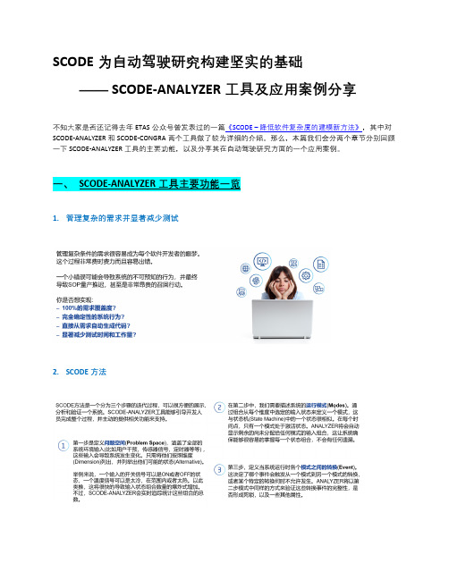
SCODE为自动驾驶研究构建坚实的基础—— SCODE-ANALYZER工具及应用案例分享不知大家是否还记得去年ETAS公众号曾发表过的一篇《SCODE –降低软件复杂度的建模新方法》,其中对SCODE-ANALYZER和SCODE-CONGRA两个工具做了较为详细的介绍。
那么,本篇我们会分两个章节分别回顾一下SCODE-ANALYZER工具的主要功能,以及分享其在自动驾驶研究方面的一个应用案例。
1.管理复杂的需求并显著减少测试2.SCODE方法3.使用SCODE-ANALYZER进行前期吃重4.“免上手”式的自动代码生成5.Fingerprints功能大幅减少测试工作量6.SCODE-ANALYZER的优势自动驾驶(AD, Autonomous Driving)系统需要掌控一个高度复杂的环境,特别是在城市交通中,自动驾驶与行人及人工驾驶车辆混合的情况下。
在设计开发的自动驾驶车辆(AV, Autonomous Vehicle)所有可能遭遇的交通状况下,都必须有一个明确且有意义的行为以系统级的需求来定义,这些系统级需求是自动驾驶车辆设计、实现和测试的基础。
正因如此,系统级需求中的不一致和缺失案例可能会导致自动驾驶车辆的不当或故障行为。
而要推导出足够完整的系统级需求所要面对的主要问题是,这些系统级需求所需要捕获的车辆的决策空间是无限大的。
对于这个问题,我们下面想要介绍的解决方案是基于SCODE-ANALYZER进行系统域分析,将自动驾驶车辆的决策空间分解为等价类。
与其他相关方法对比,它提供了一个相对完整性的保证,即在假设决策空间是完整的前提下,能够保证派生出等价类的完整性。
此应用案例引用自——<SOCA (SCODE for Open Context Analysis): Domain Analysis for Highly Automated Driving Systems>(文章链接:https:///document/9294438)发表在https:///,作者:Bosch CR案例将以城市中一个有红绿灯的十字交叉路口处的无保护右转场景进行说明。
- 1、下载文档前请自行甄别文档内容的完整性,平台不提供额外的编辑、内容补充、找答案等附加服务。
- 2、"仅部分预览"的文档,不可在线预览部分如存在完整性等问题,可反馈申请退款(可完整预览的文档不适用该条件!)。
- 3、如文档侵犯您的权益,请联系客服反馈,我们会尽快为您处理(人工客服工作时间:9:00-18:30)。
2014中国汽车高新技术发展国际论坛
市场增长趋势 – 驾驶员辅助系统
世界范围内的安装率
70% 60% 50% 40% 30% 20% 10% 0% 1990
泊车辅助功能
防侧滑功能(ESP®)
驾驶员辅助*
安全制动与转向 (ABS)
导航**
2000
2010
驾驶辅助功能被越来越广泛地应用
* 不含停车辅助和导航, ** 原始设备 Source: Bosch
2014中国汽车高新技术发展国际论坛
通向自动驾驶之路
必要的驾驶员监控 降低驾驶员监控
客户获益
高速公路辅助 交通拥堵辅助
高度自动
高速公路引导 交通拥堵引导
完全自动
整合式巡航辅助
部分自动
自适应巡航控制 车道保持支持
辅助 非自动
自动程度
22% 22% 15% 14% 14% 6% 3%
超车ቤተ መጻሕፍቲ ባይዱ误
驾驶员行为
90%以上的事故是由于驾 驶员的错误行为导致的
26%
其它失 误
事故原因3
优先权选 择错误
转向失误
不合适的速度
错误的距 离推断
驾驶员的 健康状况
1
Chassis Systems Control
2 306266 3 370632
Source: Federal Statistical Office Germany, annual report 2011, www.destatis.de accidents w/ casualties in total thereof 249 176 accidents car involved car driver involved thereof 254120 causes , up to 8 causes per accident possible
1888
1920
Chassis Systems Control
Source of pictures: Internet
2
CC/MKL-CN | 7/10/2014 | © Bosch Automotive Products (Suzhou) Co. Ltd 2014. All rights reserved, also regarding any disposal, exploitation, reproduction, editing, distribution, as well as in the event of applications for industrial property rights.
该车的最高时速限定为25英里, 无方向盘、无刹车、无侧视镜
Google针对自动驾驶的活动一直在持续改进 自动驾驶已开始纳入维也纳公约 仍需要进行针对国家法律方面的改写
* Internal Information from PJ-FA
Chassis Systems Control
8
CC/MKL-CN | 7/10/2014 | © Bosch Automotive Products (Suzhou) Co. Ltd 2014. All rights reserved, also regarding any disposal, exploitation, reproduction, editing, distribution, as well as in the event of applications for industrial property rights.
2014中国汽车高新技术发展国际论坛
自动驾驶:不再是愿景
Major OEM Activities:
维也纳公约条款变更:
高度致力于自动驾驶 大约700,000英里的开发里程 2014年5月28日谷歌展示自动驾 驶车原型
自动驾驶的立法基础 国家规范,例如责任 等是必须的
驾驶员需要在任何时候可以停止 正在执行自动驾驶的车辆
2014中国汽车高新技术发展国际论坛
事故发生 – 是促进科技进步的原因
事实上, 2013年我们仅有
~3.340 起死亡事故
1888 1920
Source: destatis 02/2014
Chassis Systems Control
Source of pictures: Internet
3
CC/MKL-CN | 7/10/2014 | © Bosch Automotive Products (Suzhou) Co. Ltd 2014. All rights reserved, also regarding any disposal, exploitation, reproduction, editing, distribution, as well as in the event of applications for industrial property rights.
2014中国汽车高新技术发展国际论坛
事故情况和驾驶员行为 1
NCAP (2012-2016) 100% 27% 16% 15% 5% 5%
超车情况
2011
事故情况
所有事故中36%的情况已 经列入立法 & NCAP
28%
其它事故
4%
变道
有人员伤亡的事 故2
十字路口 转弯
车道偏离
追尾
行人事故
100% 100%
2014中国汽车高新技术发展国际论坛
博世正在通向自动驾驶的路上
2台博世原型车已在路上测试 开发验证方式 研究法规和责任
Chassis Systems Control
9
CC/MKL-CN | 7/10/2014 | © Bosch Automotive Products (Suzhou) Co. Ltd 2014. All rights reserved, also regarding any disposal, exploitation, reproduction, editing, distribution, as well as in the event of applications for industrial property rights.
10
CC/MKL-CN | 7/10/2014 | © Bosch Automotive Products (Suzhou) Co. Ltd 2014. All rights reserved, also regarding any disposal, exploitation, reproduction, editing, distribution, as well as in the event of applications for industrial property rights.
Bosch Chassis Systems Control
功能 & 传感器 – 驾驶员辅助系统
预测性紧急制动 避让辅助 车道辅助
长距离雷达 LRR 中距离雷达 MRR 多功能摄像头 MPC
预测性行人保护
交叉路口辅助
旅行辅助
立体摄像头 Stereo Video 红外线夜视摄像头 Night Vision 超声波系统 USS 后方 / 环视摄像头 RVC, SVC
2014中国汽车高新技术发展国际论坛
外围传感器和C2X通讯
长距离雷达 探测距离: ~250 米 | 水平开角: 250米 12°; 5米 40° 夜视摄像头 探测距离: ~150米 | 水平开角: 32° 前置中距离雷达 探测距离: ~160米 | 水平开角: 160米 15°; 5米 70° 多功能摄像头 / 立体摄像头 探测距离: ~120米 (针对目标) | 水平开角: 50° (标定)
C2X通讯
超声波传感器(单个传感器) 探测距离: ~5 米 | 水平开角: 60° 后视摄像头 探测距离: ~15米 | 水平开角: 130° / 180° 多摄像头系统 探测距离: ~15米 | 水平开角: 360°
数字地图 Chassis Systems Control
后置中距离雷达 探测距离: ~90米 |水平开角: 150°
2014中国汽车高新技术发展国际论坛
先进的驾驶员辅助系统: 趋势 & 增长
长期趋势… 安全性 增值
Focus
自动驾驶
car2go Ulm
… 引领增长
欧洲 亚太 美国
2013
2015
2020
2013
2015
2020
2013
2015
2020
Chassis Systems Control
Bosch own market expectation, Status late 2013
驾驶员监控
灯光和视野辅助
泊车控制辅助
核心单元 数字地图 Car-to-X 车辆联网 仪表盘组合 + 抬头显示
Chassis Systems Control
6
CC/MKL-CN | 7/10/2014 | © Bosch Automotive Products (Suzhou) Co. Ltd 2014. All rights reserved, also regarding any disposal, exploitation, reproduction, editing, distribution, as well as in the event of applications for industrial property rights.
Chassis Systems Control
4
CC/MKL-CN | 7/10/2014 | © Bosch Automotive Products (Suzhou) Co. Ltd 2014. All rights reserved, also regarding any disposal, exploitation, reproduction, editing, distribution, as well as in the event of applications for industrial property rights.
