YASKAWA717使用说明

合集下载

YASKAWA CP-717培训课件

YASKAWA CP-717培训课件
Controller
CP-317, 316, 9200SH Maintenance Course
PPT学习交流
1
CP-717 Start-up
Group Folder Group Folder Order Folder Order Folder PLC Folder CPU Folder
Create folders.
• Program and Drawing Concepts
– Start Process Drawing, High-speed・Low-speed Process Drawing, Interruption Process Drawing
– Parent Drawing, Child Drawing, Grandchild Drawing
Grandchild
DWG. 2
FunctPioPnT1学习交流 Max. 64
Max. 99
7
Function
• Standard programs are called Functions. Anyone can retrieve at anytime.
• System Standard Functions are programmed
Child Drawing 3 Process Reference
Child DWG. 1
Grandchild DWG. 1 Process
Grandchild DWG. 2 Process
Child DWG. 2
Child DWG. 3
Max. 99
Grandchild
DWG. 1
Function 1. Process Reference

YASKAWA伺服参数设定说明

YASKAWA伺服参数设定说明

YASKAWA伺服参数设定说明YASKAWA是一家全球领先的伺服机器人和工业自动化解决方案供应商,其产品广泛应用于各种制造业领域。

为了实现最佳的运动控制性能,YASKAWA伺服系统提供了各种参数设置选项,以满足不同应用需求。

以下是YASKAWA伺服参数设定的详细说明。

1.控制方式设置:YASKAWA伺服系统提供了位置控制、速度控制和力矩控制等不同的控制方式。

根据实际应用需求,在参数设置中选择适当的控制方式。

2.增益设定:伺服系统的增益参数用于控制系统的稳定性和响应速度。

通过增益设定,可以调整伺服系统的动态响应性能。

通常,根据应用需求进行增益调整,以达到最佳的系统性能。

3.比例系数(Kp)设置:比例系数是伺服系统PID控制器的比例增益。

通过调整比例系数,可以控制系统的稳定性和快速响应性能。

通常,较高的比例系数能够快速响应外部扰动,但过高的值可能导致系统震荡。

4.积分系数(Ki)设置:积分系数是伺服系统PID控制器的积分增益。

通过调整积分系数,可以提高系统对于稳态误差的抑制能力。

通常,较大的积分系数可以减小稳态误差,但过大的值可能导致系统不稳定。

5.微分系数(Kd)设置:微分系数是伺服系统PID控制器的微分增益。

通过调整微分系数,可以控制系统的抗振性能。

较大的微分系数可以减小系统的震荡,但过大的值可能导致系统过于敏感。

6.速度限制设置:伺服系统的速度限制参数用于限制系统的最大速度。

通过设置速度限制,可以保证系统在安全范围内进行运动。

根据机器的设计和应用需求,设定适当的速度限制值。

7.力矩限制设置:伺服系统的力矩限制参数用于限制系统的最大力矩输出。

通过设置力矩限制,可以防止系统超载。

根据机器的设计和应用需求,设定适当的力矩限制值。

8.过载保护设置:YASKAWA伺服系统提供了多种过载保护选项,包括过负荷保护、过电流保护和过热保护等。

通过设置适当的过载保护参数,可以保证系统的安全运行。

9.伺服滤波器设置:伺服滤波器参数用于平滑伺服系统的输出信号。

培训三:设备所用717基本编程教材
培训三:设备所用717基本编程教材

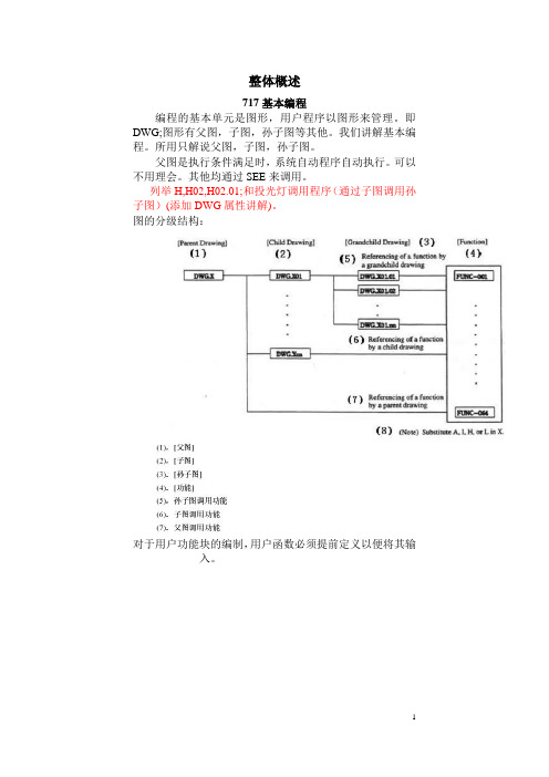
整体概述717基本编程编程的基本单元是图形,用户程序以图形来管理。

即DWG;图形有父图,子图,孙子图等其他。

我们讲解基本编程。

所用只解说父图,子图,孙子图。

父图是执行条件满足时,系统自动程序自动执行。

可以不用理会。

其他均通过SEE来调用。

列举H,H02,H02.01;和投光灯调用程序(通过子图调用孙子图)(添加DWG属性讲解)。

图的分级结构:对于用户功能块的编制,用户函数必须提前定义以便将其输入。

样例程序1.选择FSTART命令。

2.输入函数名。

显示函数的表达式。

以下对输入、地址输入及输出区进行编程。

每一区的输入举例用样例程序进行解释。

输入区对比特型数据(由B-V AL定义)的输入区如下进行编程。

1.输入N.O.触点命令。

2.选择FIN命令。

函数的输入参数与N.O.触点命令相关联对整数型数据(由I-V AL定义)、倍长整数型数据(由L-V AL定义)或实数型数据(由F-V AL定义)的输入区如下进行编程。

1.输入入口命令。

2.选择FIN命令。

函数的输入参数与入口命令相关联。

对整数型数据(由I-REG定义)、倍长整数型数据(由L-REG定义)或实数型数据(由F-REG定义)的输入区如下进行编程。

1.选择FIN命令。

函数和寄存器号(或常数)的输入参数将相互关联。

2.输入寄存器号(或常数)。

●地址输入区地址输入区的编程如下。

1.选择FIN命令。

2.输入寄存器号。

●输出区1.选择FOUT命令。

函数和线圈命令的输出参数将相互关联。

717编程的数据类型为:存储器标示:YASKAWA(安川)PLC寄存器类型及表示字地址(WORD)位地址(BIT) 功能及含义MWnnnnn MBnnnnnn 程序寄存器,MBnnnnnn对应MWnnnnn的一位MWnnnnn及MBnnnnnn在全部程序中通用DWnnnnn DBnnnnnn 子程序寄存器,DBnnnnnn对应DWnnnnn的一位DWnnnnn及DBnnnnnn只在子程序中有效Iwnnnnn IBnnnnnn 输入寄存器,IBnnnnnn对应IWnnnnn的一位IWnnnnn及IBnnnnnn在全部程序中通用Ownnnnn OBnnnnnn 输出寄存器,OBnnnnnn对应OWnnnnn的一位OWnnnnn及OBnnnnnn在全部程序中通用SWnnnnn SBnnnnnn 系统寄存器,SBnnnnnn及SWnnnnn为系统专用寄存器,有特定含义,用户只可利用,不可定义.MB003606 MB00360F1.指针标识2.内存地址3.寄存器区4.图3.1 指针标识在图3.1中,MA00100表示MW00100的内存地址nn。

安川CP717PLC指令说明
安川CP717PLC指令说明

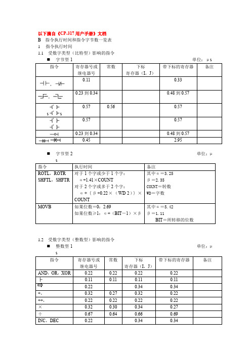
以下摘自《CP-317用户手册》文档 B 指令执行时间和指令字节数一览表 1 指令执行时间
1.1 受数字类型(比特型)影响的指令


0.23 s
s 0.23
⏹ 字节型-2 单位:μ
1.2 受数字类型(整数型)影响的指令
⏹ 整数型-1 单位:μ
A-15 整数型-2单位:μ
A-16
1.3受数字类型(实数型)影响的指令
实数型-1单位:μs
的情况。

A-17 实数型-2单位:μ
A-18
SFCSTEP 0.11
0.21

(触点转换)
+(计时器转换)0.72
A-19
(续)*1:备注栏的内容涉及的是目标字节数。

*2:如果指令附有[ ],则在目标字节数上加4或5个字节。

A-20
(续)
INS, OUTS 2
1

1

2
s s
1
1
*1:备注栏的内容涉及的是目标字节数。

*2:如果指令附有[ ],则在目标字节数上加4或5个字节。

A-21
(续)*1:备注栏的内容涉及的是目标字节数。

*2:如果指令附有[ ],则在目标字节数上加4或5个字节。

A-22
*1:备注栏的内容涉及的是目标字节数。

*2:如果指令附有[ ],则在目标字节数上加4或5个字节。

A-23
SFC 1
,,+ 1
ABOX,SBOX 1
(注)1:备注栏的内容涉及的是目标字节数。

2:如果指令附有[ ],则在目标字节数上加4或5个字节。

安川PLC通讯设定、安川CP-717注释翻译及以太网通讯、218通讯联接设定
安川PLC通讯设定、安川CP-717注释翻译及以太网通讯、218通讯联接设定

选择218通讯
默认值即可
点击详细之 后,请看下 面图示
IP地址是 笔记本电 脑的地址
双击本地连接之后出现以下画面
双击本地连接2时 出现左面对话框, 双击(TCP/IP)出 现下面对话框
设置IP地址及子网掩 码,该IP地址就是通 讯框所要填写的地址

通讯框设置好之后,再设置PLC的 通讯地址,右键N01S01点击属性之 后,出现下面通讯框。
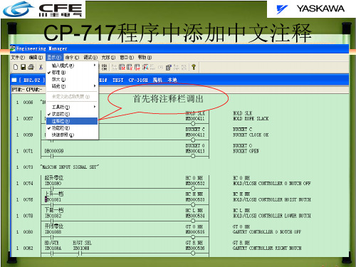
CP-717程序中添加中文注释
首先将注释栏调出
调出注释栏之后显示如下, 将光标点到IB01081处, 显示如图
第一个栏最多填写4个 汉字(直接写注释)
第二个栏最多填写24个汉字, 此栏是对前面栏的详细说明 (直接写注释)
设置通讯工程框
如果没有设置以太网通讯, 先选择逻辑端口2(任意), 点击菜单栏文件,选择设定 弹出以下对话框。
点击网络一栏,设 置逻辑端口及IP地 址。
该IP地址是PLC 的地址,后面四 台都是一样的

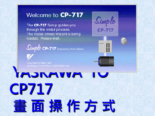
CP717使用说明
CP717使用说明
Motion Mqin Program 表示主程式
Motion sup Program 表示副程式
資料個別傳送3
按Detaile時出現視窗 MotionMainProgra mDetailSet
資料個別傳送4
選擇傳送程式
是否 傳送
傳送完畢關閉視窗
正在傳 送中
資料個別傳送5
選擇Individual File Transfer表示個別資料 傳送
F7功能鍵指定結束的行數
表示停止
F8功能鍵SP-BP之間的行數指令
F9功能鍵表示暫停
資料拷貝作業程式
修改名稱後按OK鍵.注:有 連線存在機器中無連線則 儲存在電腦.
按FILE選擇SAVE NEW FILE表示另存新檔 如程式內容相同但圈數不一樣等以拷貝的形式.
輸入產品名稱
出現對話框在 Title中輸入產品 名稱後按set確定
建立連線系統1 即電腦與機器連接
在controller name 建入機器編號
當對話框出現 Controller
folder時點擊
當對話框出現 Controller type
為機器 PLC系統
建立連線系統2
輸入機 臺編號
選擇PLC種類
建立連線系統3
點擊OK連線系 統編輯完畢.
注意:
此時畫面上任何 資料不可修改!!!
2
MPM為主
程式
檔.MPS為
副程式檔.
1
MPM251
為進氣壓程
式.
MPM252
為回原點程
式此兩項程 式不可刪除
3
4
或修改.
MPM001---進入1號程式
雙擊MPM001出現Engineering Manager(工程管理程式)

安川CP717培训教材
安川CP717培训教材

目录CP-717简介PLC程序内寄存器的分配规律 CP-717程序中常用命令和语句 PLC程序的结构程序和参数的上传与下载程序的强制与编辑程序中某些特殊点的查找方法CP-717简介CP-717软件是CP-316系列、CP-317、CP-916A、RIO-2000等控制器的软件操作平台。

软件的功能强大,操作简便。

在联机时可以进行程序的监控,配置文件,梯形图的修改,上传下载PLC程序和变频器参数,可以避免手动输入的误操作。

同时也可以用备份在编辑器内的程序或变频器参数与机上相对设备的程序或参数进行比较,以便分析和排查故障时进行对比。

脱机时可以进行软件的编辑,检查,注释的修改,变频器文件的建立,设定变频器参数PLC程序内寄存器的分配规律IW**** 输入寄存器(字)采集从I/O模块,模拟量输入模块等输入设备的字状态IB**** 输入寄存器(位)与上述字功能一致,它表示IW****字中的某一位OW**** 输出寄存器(字)将运算结果送到输出模块,模拟量模块及各通讯接口地址中去OB**** 输出寄存器(位)功能同上,一般表示输出字的一位,用于驱动数字量输出,在应用中驱动继电器等小功率执行元件MW**** 中间结果寄存器(字)用于存储PLC运算中间结果,或作为中间结果的地址MB**** 中间结果寄存器(位)用于存储中间逻辑运算结果的位状态DW****子程序内中间结果寄存器(字)功能与MW**** 相同,区别在于MW**** 在整个程序段内有效,而DW****只在本子程序段内有效,在不同的子程序段内可以重复定义使用DB****子程序内中间结果寄存器(位)功能与IB****或OB****相同。

SW**** 系统内部专用寄存器(字)用于系统内部已定义的各种状态,可记录PLC各种故障,实现定义好的各种功能,只可在程序中调用,不可定义SB**** 用于存储PLC内定义好的一些位功能状态C P 717程序中常用命令和语句On Delay[10ms]Of Delay[10ms]比较语句On Pulse有条件置“0”数据的传输条件语句调用子程序程序“段”注释整数数值限幅程序“行”注释功能块程序结束语句PLC程序的结构高速扫描程序(H程序):程序扫描时间可以定义最小10ms,用于变频器数据采集分析,变频器驱动信号给定及起升、小车、大车、俯仰机构的互锁信号。

安川程序操作指南
安川程序操作指南

YASKAWA程序操作指南第一章联机的条件及配置第一节通讯协议的配置1.首先安装CP-717软件,提供系统操作平台.2.CP-717软件安装后,在程序一栏中会有YE APPLICATION菜单,在YE APPLICATION菜单下有COMMUNICATION MANAGER和TOTAL ENGINEERING TOOL两个菜单。

3.点击COMMUNICATION MANAGER菜单,会出现COMMUNICATION PROCESS 的对话框,在对话框中设定通讯协议。

4.双击COMMUNICATION PROCESS 的对话框中的“1”,会出现LOGICAL PORT SETTING对话框,在PORT KIND选项中选SERIAL项,其它为默认,点击OK,通讯协议设置完成。

第二节子程序路径的建立及配置1.点击YE APPLICATION 菜单中的TOTAL ENGINEERING TOOL菜单,出现FILE MANAGER对话框。

2.选中FILE MANAGER对话框中的“ROOT”后,单击鼠标右健,会出现“NEW”“RENAME”“DELETE”三个选项,选中“NEW”后会出现“GROUP FOLDER”“ORDER FOLDER”,点击“ORDER FOLDER”。

3.点击“ORDER FOLDER”后,出现“MAKE NEW FOLDER”对话框,在空白处输入“ORDER NAME”如12号岸桥可输入QC12,然后回车。

4.选中QC12单击鼠标右健,会弹出“CREATE NEW FOLDER”“RENAME”“DELETE”三个选项,选中“CREATE NEW FOLDER”后会弹出“CONTROLLER FOLDER”单击“CONTROLLER FOLDER”。

5.单击“CONTROLLER FOLDER”,弹出“CONTROLLER CONFIGARATION”对话框,在“INFORMATION”目录下第一个“CONTROLLER”框中一般根据此控制器所处的网络号和站号编名如“N01S01”即一号网络一号站;“COMMENT”可不填写;第二个“CONTROLLER”为控制器的类型如“CP-317”“CP-316H”“CP-916A”“RIO2000”等等,一般“N01S01”的控制器的类型QC选“CP-317”,RTG选“CP-316H”。

安川PLC程序及软件操作演示文稿

安川PLC程序及软件操作演示文稿

如果B寄存器的当前值是ON,那么仅执行IFON到ELSE之间
设置电脑中的COM
CP717软件操作
设置电脑中的COM
CP717软件操作
设置电脑中的COM
CP717软件操作
设置电脑中的COM 选择和上面一致的COM口
CP717软件操作
设置电脑中的COM
CP717软件操作
设置电脑中的COM
CP717软件操作
打开软件后,新建一个PLC文件夹将程序复制粘贴到里面,右击箭头所指的地方
DW****子程序内中间结果寄存器(字) 功能与MW**** 相同,区别在于MW**** 在整个程序段 内有效,而DW****只在本子程序段内有效,在不同的 子程序段内可以重复定义使用
DB****子程序内中间结果寄存器(位) 功能与IB****或OB****相同。
SW**** 系统内部专用寄存器(字) 用于系统内部已定义的各种状态,可记录PLC各种故障, 实现定义好的各种功能,只可在程序中调用,不可定 义
CP717软件操作
点击箭头所对图标
CP717软件操作
点击箭头所对图标
CP717软件操作
出现下图,说明软件打开
CP717软件操作
软件通讯管理配置 打开软件后点击箭头所对的图标
CP717软件操作
软件通讯管理配置 双击箭头所对的1
CP717软件操作
软件通讯管理配置 按照箭头所指的位置点
CP717软件操作
出现下图后关闭软件
CP717软件操作
打开装软件的盘
CP717软件操作
CP717软件操作
CP717软件操作
将程序复制粘贴到下图
CP717软件操作
CP717软件操作
打开程序找到新建的40T16

安川L7变频器(可编辑)

安川L7变频器(可编辑)

安川L7变频器YASKAWAVarispeed L7CIMR-L7B200V3.7 55kW 7 93kVA400V3.7 55kW 7 106kVAYASKA W A TOCP C710676 08ATOCP_C710676_02A_0_0.book Page I Friday, April 6, 2007 8:11 PM 前言感谢您购买 Varispeed L7 系列变频器。

本使用说明书介绍了如何正确使用Varispeed L7系列。

在使用安装、运行、维护、检查等前,请务必认真阅读本使用说明书。

另外,请在理解产品的安全注意事项后再使用该产品。

一般注意事项为了说明产品的细节部分,本说明书中的图解有时是卸下外壳或安全遮盖物时的状态。

运行本产品时,请务必按规定装好外壳或遮挡物,并按照使用说明书的内容进行运行。

本使用说明书中的图示仅为代表例,可能会与您订购的产品有所不同。

由于产品改良或规格变更,以及为了提高使用说明书的便利性,本使用说明书的内容会及时变更。

由于损坏或遗失而需要订购使用说明书时,请向本公司代理店或封底上记载的离您昀近的本公司营业所联系,并告知封面上的资料编号。

安装在产品上的铭牌如果已经字迹模糊或发生破损,请向本公司代理店或封底上记载的离您昀近的本公司营业所订购。

ITOCP_C710676_02A_0_0.book Page II Friday, April 6, 2007 8:11 PM 与安全有关的标记说明本手册根据与安全有关的内容,使用了下列标记。

有安全标记的说明,表示重要内容,请务必遵守。

表示错误使用时,将会引发危险情况,导致人身伤亡。

表示错误使用时,将会引发危险情况,导致轻度或中度人身伤害,损坏设备。

另外,即使是注意事项,根据具体情况,有时也可能导致重大事故。

有关危险的标识,ISO标准与 JIS标准各有不同。

ISO标准 JIS标准本手册中使用了基于 ISO标准的标识。

产品的警告标签可能有ISO和JIS两种标准,两种规格请同样对待。

YASKAWA CP717培训 ppt课件

YASKAWA CP717培训 ppt课件

Child Drawing 1 Process Reference
Child Drawing 2 Process Reference
Child Drawing 3 Process Reference
Child DWG. 1
Grandchild DWG. 1 Process
Grandchild DWG. 2 Process
(Here ••: 01 ~ 99)
• Same rule is applied to low-speed, start and interruption process.(Drawing type H changes to L, A and I respectively.)
• Function:FUNC-001-064 • Child drawing can be called by SEE H01 in program
Input USER-A in “User Name”. After moving a cursor with TAB key, input USER-A in “Password” again. Then click “OK”.
Log ON Complete
3
On-Line Communication Parameter Setting
High-speed Scan
High-speed Scan
High-speed Scan
Interruption Signal
Power ON
6
Parent Drawing, Child Drawing, Grandchild Drawing
Parent Drawing 1 page
(One drawing per start, interruption, high-speed and low-speed.)

717电子测量放大器说明书

717电子测量放大器说明书

Gage Amplifiers, HardnessTesters, Surface Testers717 Electronic Gage Amplifier with 252 Transfer Gage and 715-1Z Gaging Headf eA tures• Dual inputs for cumulative/differential measurements • Selectable inch or millimeter ranges • Selectable digital or analog output • Simple "push-button" calibration• Mirrored gage display for parallax-free readability • Rugged metal case can be used anywhere in the shop • Uses standard Starrett lever and cartridge-type probes • Remote zero using PC• Front panel data send button• Single and continuous data send modes• Serial Data Output via front panel button, PC or optional foot switchA ccurAcy• Within ±2% of full scalep oWer r equIreMents• 110 volt VAC/60Hz (AC adapter furnished)d A t A o utput• Digital: ASCII serial data • Analog: ±2.5 VDC/Full scales IZe• D imensions: 9-1/4" Height x 5-1/2" Width x 5-1/2" Depth (235 x 140 x 140mm) • Weight: 6 lb (2.7kg)717232f eA tures• 7" Android tablet with intuitive software application foreasy process monitoring, setup, and data export• Flexible data requesting and logging (.CSV to Micro SD Card, E-mail, PC transfer) with programmable auto logging and collection•Simultaneous connection of up to four devices (Indicators, Calipers, Micrometers, Probes, etc.)• Supports both Digimatic and Quadrature gaging systems • "Send All" or "Request All" data to/from all gages • TIR, Max., Min. and Freeze Hold, Travel Reverse • USB Type A and B, RS232 connection • High quality, low profile enclosure • Bright LED power indication • IN, MM and No Units setting • Programmable Ratios • Four channel viewRMS2704233starrett .comG a G e a m p s , H a r d n e s s a n d s u r f a c e T e s T e r sNew!The 776 accepts multiple gage inputs simultaneously – invaluable for applications such as this Starrett special gage fixturef eA tures• Large (6") color flat-panel LCD screen built intoa compact ergonomically designed case with an adjustable tilt base allows comfortable positioning for the operator• Supports 1, 4 or 8 input channels. These can be mathematically combined to display dimensions such as flatness, volume or runout.• Screens include individual readings with the capacity to display four lines simultaneously (each line 9/16" high), bar and dial position style displays, graphs and histograms of measurement statistics, and tables of measurement and SPC data• Supports Starrett 776 LVDT probes and Heidenhain Specto style 12mm and 30mm range digital probes • Measurements can be taken by the operator or in a semi-automated manner• Large comfortable buttons allow easy selection of measurement functions, display screen changes, data entry and zeroing the screen• Speaker and external jack outputs can be adjusted to compensate for noisy work environments. Earphones can be plugged into speaker jack for silent operation.• Two 3 x 1/2" keys placed over the screen can be programmed as hot keys for frequently used functions • Optional foot switch available776234G AGe AMplIfIersDRO View: Gage-Chek ™ 776 features large, easy-to-read numerical display with custom dimension labels. Out of tolerance conditions are quickly identified by a change to red. Icons indicate that a process study has been performed, complete with in/out of tolerance alert. Mode switches include inch/metric, absolute/incremental, decimal degree/degrees, minutes, seconds.Displays all gages plugged into the gage chek at one time. It automaticallydisplays marginal and error indications with multi-color display.Heidenhain Specto Length Probes776 LVDT Probes715-2Z715-7715-8715-9235starrett .comG a G e a m p s , H a r d n e s s a n d s u r f a c e T e s T e r sG AGe A MplIfIers715 e lectronIc G AGe A MplIfIer G AGe H eAds715-1Z l ever -t ype H eAd• Mounts directly in place of dial indicators with dovetail or AGD lug-type backs • .078" (2mm) diameter contact standard .031" (0.8mm) and .062" (1.6mm)• Diameter carbide contacts are available715-2Z* c ArtrIdGe -t ype H eAds• Hardened steel contact with radius tip. Head will accept all standard AGD contact points.• .375" (9.5mm) mounting diameter allows replacement of standard AGD dial indicators715-6, 715-7, 715-8, And 715-9 c ArtrIdGe -t ype H eAds• Tungsten carbide ball contacts• Head will accept any AGD style contact**• Half-bridge construction, stainless steel body• .375" (9.5mm) mounting diameter allows replacement of standard AGD dial indicators715-1Z715-2Z715-6715-7715-8715-9* Longer range cartridge-type gaging heads are available, quoted on application.** 715-9 head will accept all standard AGD contacts.236f eA tures• Ability to handle Rockwell Scales A through H and K • Stable cast iron construction• Ideal basic hardness testing for many typical applications • Digital readout available38143814E237GaGeamps,HardnessandsurfaceTesTers New!f eA tures• Direct analog dial reading• Advanced design provides Rockwell and RockwellSuperficial testing• Easy to operate• Engineered to provide highly sensitive and accurate readings• Conforms to ASTM E-18• Tests Rockwell Scales: A, B, C, D, E, F, G, H, K, L, M• Tests Superficial Rockwell Scales: HR15N, HR15T,HR30N, HR30T, HR45N, HR45Ts• Includes a diamond conical indentor, 1/16" ball indentor,HRC, HRB, HR15N, HR30N and HR45T test blocks,5.87" (150mm) test table, 2.5" (63mm) flat anvil,standard vee anvil, accessory case and dust cover3815238f eA tures• Fully automated routines reduce operator involvement and speeds measurements• Large touch screen display• Programmable scale conversions, dwell times and sample counter• Sample averaging is automatically calculated• RS232C output• Built in mini-printer for outputting readings• USB output3816B239 G a G e a m p s , H a r d n e s s a n d s u r f a c e T e s T e r sH Ardness t estInGRockwell and Brinell test blocks at a variety of hardness levels. (A) Aluminum Brinell, (B) Steel Brinell, (C) Vickers, (D) Rockwell, (E) 187.5kg/2.5mm Brinell, (F) Extra-Soft Rockwell and (G) Brass Rockwell.t est b locKs And A ccessorIes for H Ardness t estersStarrett blocks can be used to test Rockwell, Brinell or Vickers scales. They are available in steel, brass and aluminum. Each block is serialized, with a certificate detailing the environmental conditions used to test the block.Actual readings are given, with the averages of these readings: min. reading, max reading and a repeatability figure. The blocks are calibrated according to ASTM E-18 standards, ANSI (NCSL) Z540-1, (ISO) 10012-1, ISO/IEC 17025 and Mil-std 45662A.Starrett hardness test blocks are manufactured from square steel or brass plates, as opposed to the more common round bar stock. The use of the plate gives a more accurate and consistent surface for inspection. Metallurgical tests have proven that during the production of round bar stock, suspended carbides in the mix migrate to the center of the rod. The scientific name for this condition is carbide segregation and results in different readings being found in the center of a rod rather than at its outer edges. Some manufacturers remedy this situation by removing the centers from their blocks.Hardness test blocks are designed to be used only on one side and the indents should be more than .010" from the centers of two indents or no closer to the block's edge than .040".Calibration kits are also available from Starrett. No facility with a hardness tester in use should be without a calibration kit. These kits come with from 3 to 20 calibrated test blocks and the serialized penetrator that was used to inspect each of the blocks in the set. When a discrepancy is detected in a tester, these kits allow you to determine the direction to proceed to resolve the issue.GABCDEFwithin acceptable limitswithin acceptable limits240Standard and special anvilsPT05272 HRC 3-Block Master Calibration KitABCDEFGPenetrators - Contact Starrett for more informationCAE1/2" spot anvil - special orderBDExtended 1/4" spot anvil - special order241starrett .comG a G e a m p s , H a r d n e s s a n d s u r f a c e T e s T e r s3811A c oMpAct H Ardness t esterThe 3811A is a state of the art, digital portable hardness tester, designed to test the hardness of large, hard metal parts.The 3811A combines fast test speeds with ample memory and output. It performs tests that easily convert to most popular hardness scales such as Rockwell, Brinell, Vickers and Shore.This compact hardness tester is loaded with useful functions usually found only on high priced models.CDDLGOptional Remote Impact DevicesIncludes base instrument, impact device D, calibrated test block, custom carry case, cleaning brush and operation manualH Ardness t esterss pecIfIcA tIons• Accuracy: ±0.5% (referred to L=800) • Repeatability accuracy: ± 4L units (L=Leeb)• Measuring range: 200-960 HL• For steel and cast steel, alloy tool steel, stainless steel, grey cast iron, spheroidal iron, cast aluminum, brass, bronze, wrought copper alloy• Tool steel should be about 1" thick solid material or larger • Operating temperature: 5-104 °F• Dimensions: 5.96 x 2.938 x 1.270" (150 x 74 x 32mm)• Weight: 8.6 oz. (245 grams)f eA tures• Leeb style tester designed for large, hard parts – load the impact body and place the impact device on your test piece• Easy to use keypad operation – push the button to begin testing and obtain reading • Auto identification of impact device • Large LCD display with back light • USB ouput• Automatic conversions to Rockwell, Brinell, Vickers and Shore• Automatic mean value as well as Min and Max values • Uses two AA alkaline batteries with low power indicator • Memory capacity (100 groups)• Optional impact devices and special support rings2423810A d IGIt Al p ort Able H Ardness t esterThe 3810A is a state-of-the-art digital instrument designed to test the hardness of large hard metal parts. Loaded with useful functions such as USB output and a built in printer, the 3810A is an ideal choice for fast, accurate hardness testing. This versatile tester can perform tests that easily convert to the most popular hardness scales, including Rockwell, Brinell, Vickers and Shore.The tester is easy to use. Simply load the impact body, place the impact body on your test piece, then push the button to begin testing.The 3810A is designed to test large hard parts that cannot be brought to a benchtop machine. For example, tool steel should be close to 1" thick of solid material. The 3810A comes with a D impact device, calibration block, cleaning brush, manual and a carrying case.s pecIfIcA tIons• Accuracy: ±0.5% (referred to L=800)• Repeatability accuracy: ±4L units (L=Leeb)• Measuring range: 200-960 HL• Materials: steel & cast steel, alloy tool steel, stainless steel, grey cast iron, spheroidal iron, cast aluminum, brass, bronze, wrought copper alloy• Battery type: AA alkaline (4)• Operating temperature: 5-104 °F• Dimensions: 150 x 74 x 32mm• Weight: 245 grams• Includes 3810A tester, impact device D, calibration test block, cleaning brush, operation manual, custom carry case• Available options include DC, D+15, DL, G, C impact devices, and special support ringsf unctIons• Easy to use keypad operation• Auto identification of impact device• Large LCD display with back light• USB ouput• Automatic conversions to: Brinell, Rockwell B & C, Vickers and Shore• Automatic mean value as well as Min & Max values • Battery indicator• Memory capacity (100 groups)H Ardness testers3810A243 G a G e a m p s , H a r d n e s s a n d s u r f a c e T e s T e r sA pplIcA tIon And H Ardness r AnGes for s t Arrett H Ardness I MpAct d evIcest ecHnIcAl d A t A for s t Arrett H Ardness I MpAct d evIcesH Ardness testers244representative for additional or special requirements.SR160245starrett .comG a G e a m p s , H a r d n e s s a n d s u r f a c e T e s T e r sNew!60.862•31•460.862•31•4Standard Pick-Upfor general surface roughness measurement Code SR-112-1502 (5µm tip radius)Code SR-112-1503 (10µm tip radius)Right Angle Pick-Upfor measurement at right angles to the direction of traverse Code SR-112-150514•560.268•20•81•82•560.963•5Small Bore Pick-Up for general use in small bores, grooves and on narrow surfaces Code SR-155-P28495Recess Pick-Upfor measuring into deep recess Code SR-112-1506 recess 5.7mm (0.23")246e lectronIc d uroMeters3805b e lectronIc d uroMeterThe 3805B meets ASTM D2240-05, "Standard Method For Rubber Properties - Durometer Hardness". It is designed to fit comfortably and firmly in your hand. Its large LED display and simple three button control make the 3805B Durometer easy to use.The 3805B measures Shore A values for a wide variety of soft materials including: rubber: soft vulcanized (i.e. tire), natural nitrile; elastomeretric materials (rubber and rubber-like ): GR-S, GR-1, neoprene, thiokol, flexible polyacrylic esters; other softer materials including wax, felt, leather, etc. (materials that would normally yield under fingernail pressure).f eA tures And s pecIfIcA tIons• Meets ASTM standards for durometer hardness• Extra large LED display• Simple 3-button control• Auto Hold feature• Measuring range: 0-100 HSA• Deviation: <1% H• Resolution: 0.5 H• Accurate and repetitive deviation = 20~90HSA• HSA <±1 grade•Custom carrying case3805B247GaGeamps,HardnessandsurfaceTesTersf eA tures And s pecIfIcA tIons• 4 digit LCD display with back light• Upper/Lower limit preset alarm• Measurement and scanning capabilities• Adjustable sound velocity• Extended memory• 20 memory groups (100 files/group)• Minimum display unit: 0.001" (0.01mm) selectable• .040-12.0" measuring range (in steel with standard probe)• 3280-32805ft/s (1000-9999m/s) sound velocity range• 32-122 °F operating temperature• 5MHz Frequency• 4Hz update range• USB output• Power supply: Two 3V AA alkaline batteries withapproximately 100 hours of life (with the backlight off)• Power consumption: Working current is less than 3V• Accuracy: ± (0.5% thickness + .001")• Dimensions: 5.90 x 2.91 x 1.30" (150 x 74 x 33mm)• Weight: 8.6oz (245g)• Includes tester and cables, software, USB cable,couplant gel and a rugged, form fit carrying case Array 3812248f eA tures And s pecIfIcA tIons• Measuring range: 0-40mils (0-1000µm) max.• Resolution: 0.1µm/0.1mils (0-99µm) or 1µm (over 100µm)• Guaranteed tolerance (after one-point calibration): ±1-3%n or 2µm (whichever is greater)• 4-digit display, .40" (10mm) height,• Minimum measuring area: .20 x .20" (5 x 5mm)• Minimum radius of curvature: Convex: .12" (3mm), Concave: 1.2" (30mm)• Minimum substrate thickness: Ferrous: 20 mils(0.5mm), Non-ferrous: 2 mils (50µm)• Zero calibration• Foil calibration• Maximum surface temperature of test object: 302 °F(maximum contact time 2 seconds)• Power source: Four AA batteries• Includes steel and aluminum substrate samples• Includes four calibrated thickness samples• Dimensions: 6.39 x 2.74 x 1.27" (161 x 69 x 32mm)• Weight: 9oz. (260g)3813249 G a G e a m p s , H a r d n e s s a n d s u r f a c e T e s T e r s。

CP717软件使用

CP717软件使用

YASKAWA(安川)PLC编程语言CP-717的结构及使用介绍 安川PLC控制软件CP-717内部功能完善,通讯及运算功能强大,能对PLC及变频器实施精密控制.CP-717支持CP-316,CP-316H,CP-317,CP-916A等PLC,可以进行远程I/O接收模块120I/O、2000I/O模块配置,另外可以和INVERTER通过216IF 建立通讯,实时监视、修改INVERTER参数等功能。

通过CP-717编程软件,可以方便的进行PLC离线编程、在线修改。

第一节 C P-717使用.启动和退出1 启动通讯过程本节说明如何开始CP-717和PLC之间的通讯过程。

1.1 打开通讯过程窗口打开通讯过程窗口双击台式机的屏幕上的“YE_Application”(YE_应用程序)图表,然后双击,“YE_Application”(YE_应用程序)窗口中的“Communication Manager”(通讯管理器)图标。

① 通讯过程窗口打开。

1.2 设置通讯过程(串联通讯)设置通讯过程①单击将要使用的端口的逻辑端口号。

② 通讯过程菜单的“File (F)”(文件)中选择“Setting(E)”(设置)。

③ 在对话框中,将“Port Kind”(端口类型)设定为“Serial”(串联),并且单击[Detail](细节)按钮。

④ 在对话框中,进行串联端口设置。

设置“波特率”到“9600”或“19200”。

保持“数据字节”、“奇偶性校验”和“停止字节”为默认设置。

然后单击[OK]按钮。

⑤ 在上述第(3)步逻辑端口设置的对话框中单击[OK]按钮。

串联通讯的信息在通讯过程窗口中设置。

⑥ 通讯过程菜单中的“文件(F)”中选择“保存(S)”。

⑦ 在消息框中,单击“是(Y)”按钮。

⑧ 在通讯过程菜单中的“文件(F)”中选择“退出(X)”。

通讯过程设置在关闭并重新启动通讯过程窗口后生效。

因为在启动CP-717时,通讯过程也同时开始,因此只要CP-717还未启动,无需重新启动通讯过程。

安川CP717培训教材 20170101

安川CP717培训教材 20170101

岸桥系统程序的速度指令


起升:H3.1=〉H3=〉H6=〉H4.1(模拟量) 小车:H3.1=〉H3=〉H8=〉H4.1(模拟量) 俯仰:H3.1=〉H3=〉H9=〉H4.1(模拟量) 大车:H3.1=〉H3=〉H7=〉H4.1(模拟量)
岸桥系统程序的运行指令


起升:H2.1、H2.2=〉H17=〉H17.1=〉 H17.2=〉H4.2(数字量) 小车:H2.1、H2.2=〉H19=〉H19.1=〉 H19.2=〉H4.2(数字量) 俯仰:H2.1、H2.2=〉L20=〉L20.1=〉 L20.2=〉H4.2(数字量) 大车:H2.1、H2.2=〉H18=〉H18.1=〉 H18.2=〉H4.2(数字量)
--结束--
信号处理流程(起升)


起升机构手柄信号的处理在H3、H3.1中完成 GLAY码---〉二进制的转换,做出手柄曲线, 送到H6中进行控制。 H3中手柄信号处理后---〉H6中进行变频器给 定信号的处理,在H6中MHREF功能模块完成手 柄信号采集、减速、判断、减速范围设定、恒 功率系数运算、加减速时间运算,最终输出到 变频器与PLC的接口地址中。 H6中经加减速曲线处理后的信号---〉H4.1中进 入接口地址程序---〉CP916A进行地址转换---〉 VS676H5中进行变频器速度给定控制。
在 Online 状 态 下 CPUHD
程序的比较功能
参数的上传/下载与比较
参数的上传 参数的下载 参数的比较
程序的编辑(DB0000处并联MB2303常开点)


把“光标”移至DB0000处,按功能键F1 (INSERT),回车。 做“左分支”和“右分支”。 光标下移一行,做“常闭点”,并输入 MB2303。 光标移至MB2303处,并封口。 按功能键F1(INSERT)。 按功能键F9(SAVE)。

安川用户程序手册

安川用户程序手册

前言首先,感谢领导的信任,给我这样一个在技术上跟大家沟通交流的机会。

我接触码头行业的时间并不长,对安川系统不算太了解。

今天我把我对安川电控系统的一些感受拿出来跟大家一同分享,给大家提供一种思维方式上的借鉴。

本人才疏学浅,水平有限,如有讲错的地方,请大家指正。

这次我的安川系统培训内容分为五章:第一章变频器运行第二章编码器第三章故障检测第四章四大机构运行第五章交流辅机由于时间有限,我重点讲解整机模拟量部分的计算。

安川电控系统的程序结构大致分为上述五个部分,整个程序都是以变频器为核心,围绕变频器运行而设计,所以变频器运行是程序中重中之重。

第一章:变频器运行第一节:安川变频器与CP717间双向通讯字1.1安川变频器与CP717间双向通讯字概述注:3,4,15,16输入字可由参数设置成速度环增益值或转矩限制值。

3,4,15,16输出字可由参数设置成任意模拟量输出参量。

红色,蓝色代表岸桥程序中实际应用字。

―――――代表岸桥程序中备用或空缺字。

黑色代表岸桥变频器未使用字(除开环V/F,VEC外)。

1.2变频器输出模拟量信号反馈1.3变频器运行所需的模拟量1.3.1速度给定值1.3.2转矩限制值1.3.3转矩补偿值1.3.4速度环(比例)增益值1.4运行命令字-OW910注:红色代表岸桥程序中实际应用字。

――代表岸桥程序中备用或空缺字。

黑色代表岸桥变频器未使用字(除开环V/F,VEC外)。

1.4.1基极封锁命令1.4.2运行(正转)命令1.4.3反转命令1.4.4故障复位命令1.4.5初始励磁命令1.4.5选择2#电机命令1.4.6速度环积分取消命令V/F节能控制命令VEC速度环/电流环切换命令暂停命令速度跟踪命令加减速时间切换命令1.5状态字-IW9001.5.1变频器状态字缓存1.5.2变频器状态字零侍服OK1.6故障字1-IW90AH3F67=0011111101100111DW12=OC,GF,OV,UV3,FU,OH,OH1,OL2,OL3,OL4,OL1DB120=MB12060=OC, DB121=MB12061=GF,DB122=MB12062=OVDB125=MB12065=UV3,DB126=MB12066=FU,DB127=MB12067(备用), DB128=MB12068=OH1,DB129=MB12069=OH2,DB12A=MB1206A=OL2, DB12B=MB1206B=OL3,DB12C=MB1206C=OL4,DB12D=MB1206D=OL11.5故障字2-IW90B起升电机超速大车电机超速H3F67=0001110111000011DW13=RR,RH, PF,LF,SC,OPR,CE,CPFDB130=MB12070=RR,DB131=MB12071=RH,DB132=MB12072=EF1-EF8(备用)DB136=MB12076=PF, DB137=MB12077=LF,DB138=MB12078=SC,DB139=MB126079备用DB13A=MB1207A=OPR,DB13B=MB1207B=CE,DB13C=MB1207C=CPF,第二节变频器模拟量给定系统2.1格雷码格雷码又叫反射码或循环码,它是一种数学排序系统,其中的所有相邻整数在它们的数字表示中只有一个数字不同。

YASKAWA机器人示教器简单操作

YASKAWA机器人示教器简单操作

YASKAWA机器人示教器简单操作本文档将介绍YASKAWA机器人示教器的简单操作步骤。

步骤一:打开示教器首先,确保示教器已连接到机器人控制器的端口。

然后,按下示教器上的电源按钮,将其打开。

步骤二:选择示教模式一旦示教器打开,您将看到一个菜单屏幕。

使用示教器上的方向键导航到"示教模式"选项,并按下"确认"按钮以选择它。

步骤三:示教位置在示教模式下,您可以示教机器人移动到特定位置。

按下示教器上的"示教位置"按钮,然后使用示教器上的方向键来调节机器人的位置。

可以通过示教器上的数字键输入特定坐标值。

步骤四:示教路径除了示教位置,您还可以示教机器人沿一条特定的路径移动。

按下示教器上的"示教路径"按钮,并使用方向键指定机器人的路径。

您可以按下"确认"按钮来保存路径。

步骤五:验证示教完成示教操作后,您可以使用示教器上的"验证"按钮来测试示教是否正确。

按下此按钮后,机器人将按照您示教的位置或路径进行移动。

步骤六:保存示教程序如果示教操作无误,您可以保存示教程序以备以后使用。

按下示教器上的"保存"按钮,并按照屏幕上的指示进行操作。

确保为程序选择一个合适的名称,并按下"确认"按钮来保存。

步骤七:关闭示教器最后,当您完成示教操作并保存示教程序后,按下示教器上的电源按钮以将其关闭。

以上就是YASKAWA机器人示教器的简单操作步骤。

请按照上述步骤进行操作,并根据实际需要进行示教。

YASKAWA CP717使用方法与技巧解析

YASKAWA CP717使用方法与技巧解析

YASKAWA CP-717 使用方法与技巧解析烟台港联合港埠公司梁晓东摘要本文从程序安装与数据装载方法、计算机与PLC联机工作的方法技巧,两大方面的10项技术细节入手,对YASKAWA CP-717 Engineering Tool(Version: 4.71)使用方法与技巧进行了完整阐述,对提高系统维护水平,具有指导意义。

关键词程序安装联机工作技巧Abstract: This paper give a total explain for how to use YASKAWA CP-717 Engineering Tool(Version: 4.71),from two sides :“set up”and “data load”,communication ways between pc and plc ,include ten technology details ,All this is significance to improve system service technology.Keywords: set up communication skillYASKAWA CP-717 Engineering Tool是安川PLC+变频驱动系统的支持软件,被广泛应用在40吨门机的驱动系统。

本文对其使用方法与技巧进行解析,以解答工程技术人员在使用该软件时经常遇到的难题。

一、程序安装与数据装载方法YASKAWA CP-717 Engineering Tool包含3个文件夹,一是YSAD717V4.71_源程序文件夹,二是CMT_用户程序注释信息文件夹,三是用户自命名的指令文件夹(用于存放用户程序)。

使用复制或发送命令,将这三个文件复制到U盘、移动硬盘后,注意不要继续使用复制或发送命令,进行安装,应当使用安装程序,完成该软件在新计算机上的安装工作。

1、打开YSAD717V4.71_源文件程序文件夹你会看到有以下内容:215PCI文件夹,V047文件夹,AUTORUN 安装信息,INSTALL可执行文件。

  1. 1、下载文档前请自行甄别文档内容的完整性,平台不提供额外的编辑、内容补充、找答案等附加服务。
  2. 2、"仅部分预览"的文档,不可在线预览部分如存在完整性等问题,可反馈申请退款(可完整预览的文档不适用该条件!)。
  3. 3、如文档侵犯您的权益,请联系客服反馈,我们会尽快为您处理(人工客服工作时间:9:00-18:30)。
YASKAWA(安川)PLC软件结构及使用概述
安川PLC控制软件CP-717内部功能完善,通讯及运算功能强大,能对PLC及变频器实施精密控制.
1)高速扫描程序结构
N01S01中的高速扫描程序主要实现对起升机构,大车机构,小车机构,俯仰机构的运行控制,位置检测及对各机构变频器实施精密控制,并实时采集变频器的各项参数,进行运算判断保证各机构安全,可靠的运行.
215通讯
RIO-2000单元
I/O模块I
I/O模块I
I/O模块I
I/O模块I
I/O模块I
I/O模块I
216通讯
大车PG小车PG
大车PG
起升PG
6)故障查找流程
联机打开程序的步骤
程序寄存器,MBnnnnnn对应MWnnnnn的一位
MWnnnnn及MBnnnnnn在全部程序中通用
DWnnnnn
DBnnnnnn
子程序寄存器,DBnnnnnn对应DWnnnnn的一位
DWnnnnn及DBnnnnnn只在子程序中有效
Iwnnnnn
IBnnnnnn
输入寄存器,IBnnnnnn对应IWnnnnn的一位
IWnnnnn及IBnnnnnn在全部程序中通用
Ownnnnn
OBnnnnnn
输出寄存器,OBnnnnnn对应OWnnnnn的一位
OWnnnnn及OBnnnnnn在全部程序中通用
SWnnnnn
SBnnnnnn
系统寄存器,SBnnnnnn及SWnnnnn为系统专用寄存器,有特定含义,用户只可利用,不可定义.
MB003
3
4
5
6
7
8
9
A
B
C
D
E
F
MW00360
5)电控系统构成示意图
VS-616G5
起升/大车1#
变频器
VS-616G5
大车2#
变频器
VS-616G5
小车变频器
RIO-2000单元
I/O模块I
I/O模块I
I/O模块I
I/O模块I
I/O模块I
I/O模块I
CP316H
主CPU
2)低速扫描程序结构
N01S01中的低速扫描程序主要进行各辅助机构的控制(如大车的转向机构,倾转机构,吊具机构等)及故障信号的处理
3)程序的逻辑部分结构形式画面
4)程序的运算及数据处理结构形式画面
YASKAWA(安川)PLC寄存器类型及表示
字地址(WORD)
位地址(BIT)
功能及含义
MWnnnnn
MBnnnnnn
相关文档
最新文档