N4030 usb-lan Wistron Arsenal DJ1 Dis I_O
微软无线光学桌面4000系列说明书
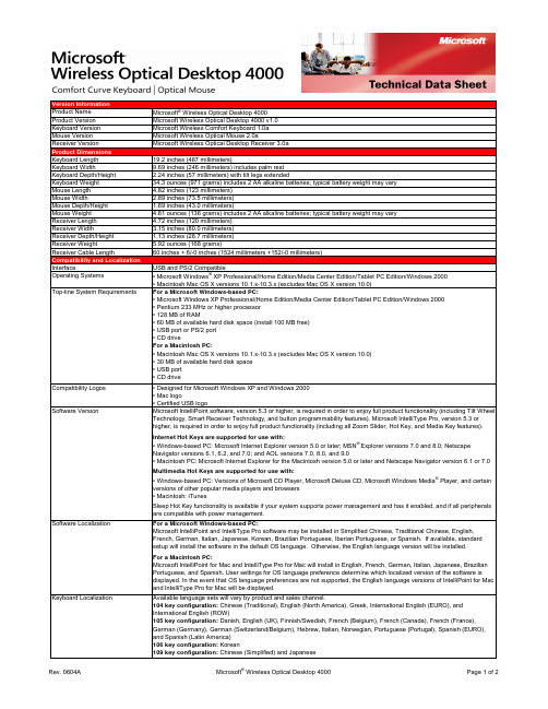
Version InformationProduct Name Microsoft® Wireless Optical Desktop 4000Product Version Microsoft Wireless Optical Desktop 4000 v1.0Keyboard Version Microsoft Wireless Comfort Keyboard 1.0aMouse Version Microsoft Wireless Optical Mouse 2.0aReceiver Version Microsoft Wireless Optical Desktop Receiver 3.0aProduct DimensionsKeyboard Length19.2 inches (487 millimeters)Keyboard Width9.69 inches (246 millimeters) includes palm restKeyboard Depth/Height 2.24 inches (57 millimeters) with tilt legs extendedKeyboard Weight34.3 ounces (971 grams) includes 2 AA alkaline batteries; typical battery weight may varyMouse Length 4.82 inches (123 millimeters)Mouse Width 2.89 inches (73.5 millimeters)Mouse Depth/Height 1.69 inches (43.0 millimeters)Mouse Weight 4.81 ounces (136 grams) includes 2 AA alkaline batteries; typical battery weight may varyReceiver Length 4.72 inches (120 millimeters)Receiver Width 3.15 inches (80.0 millimeters)Receiver Depth/Height 1.13 inches (28.7 millimeters)Receiver Weight 5.92 ounces (168 grams)Receiver Cable Length60 inches + 6/-0 inches (1524 millimeters +152/-0 millimeters)Compatibility and LocalizationInterface USB and PS/2 CompatibleOperating Systems• Microsoft Windows® XP Professional/Home Edition/Media Center Edition/Tablet PC Edition/Windows 2000• Macintosh Mac OS X versions 10.1.x-10.3.x (excludes Mac OS X version 10.0)Top-line System Requirements For a Microsoft Windows-based PC:• Microsoft Windows XP Professional/Home Edition/Media Center Edition/Tablet PC Edition/Windows 2000• Pentium 233 MHz or higher processor• 128 MB of RAM• 60 MB of available hard disk space (install 100 MB free)• USB port or PS/2 port• CD driveFor a Macintosh PC:• Macintosh Mac OS X versions 10.1.x-10.3.x (excludes Mac OS X version 10.0)• 30 MB of available hard disk space• USB port• CD driveCompatibility Logos• Designed for Microsoft Windows XP and Windows 2000• Mac logo• Certified USB logoSoftware Version Microsoft IntelliPoint software, version 5.3 or higher, is required in order to enjoy full product functionality (including Tilt Wheel Technology, Smart Receiver Technology, and button programmability features). Microsoft IntelliType Pro, version 5.3 orhigher, is required in order to enjoy full product functionality (including all Zoom Slider, Hot Key, and Media Key features).Internet Hot Keys are supported for use with:• Windows-based PC: Microsoft Internet Explorer version 5.0 or later; MSN® Explorer versions 7.0 and 8.0; NetscapeNavigator versions 6.1, 6.2, and 7.0; and AOL versions 7.0, 8.0, and 9.0• Macintosh PC: Microsoft Internet Explorer for the Macintosh version 5.0 or later and Netscape Navigator version 6.1 or 7.0Multimedia Hot Keys are supported for use with:• Windows-based PC: Versions of Microsoft CD Player, Microsoft Deluxe CD, Microsoft Windows Media® Player, and certainversions of other popular media players and browsers• Macintosh: iTunesSleep Hot Key functionality is available if your system supports power management and has it enabled, and if all peripheralsare compatible with power management.Software Localization For a Microsoft Windows-based PC:Microsoft IntelliPoint and IntelliType Pro software may be installed in Simplified Chinese, Traditional Chinese, English,French, German, Italian, Japanese, Korean, Brazilian Portuguese, Iberian Portuguese, or Spanish. If available, standardsetup will install the software in the default OS language. Otherwise, the English language version will be installed.For a Macintosh PC:Microsoft IntelliPoint for Mac and IntelliType Pro for Mac will install in English, French, German, Italian, Japanese, BrazilianPortuguese, and Spanish. User settings for OS language preference determine which localized version of the software isdisplayed. In the event that OS language preferences are not supported, the English language versions of IntelliPoint for Macand IntelliType Pro for Mac will be displayed.Keyboard Localization Available language sets will vary by product and sales channel.104 key configuration: Chinese (Traditional), English (North America), Greek, International English (EURO), andInternational English (ROW)105 key configuration: Danish, English (UK), Finnish/Swedish, French (Belgium), French (Canada), French (France),German (Germany), German (Switzerland/Belgium), Hebrew, Italian, Norwegian, Portuguese (Portugal), Spanish (EURO),and Spanish (Latin America)106 key configuration: Korean109 key configuration: Chinese (Simplified)and JapaneseTracking TechnologyMouse Tracking System Microsoft-proprietary optical technologyImaging Rate Dynamically adaptable to 6000 frames per secondX-Y Resolution400 points per inch (15.75 points per millimeter)Tracking Speed Up to 36 inches (914 millimeters) per secondWireless TechnologyWireless Platform27 MHz Radio Frequency (RF)Wireless Channels• Keyboard: 27.095 MHz channel 0, 27.195 MHz channel 1• Mouse: 27.145 MHz Mouse channel 1Wireless IDs• Keyboard: Over 65,000 random identification codes• Mouse: Over 65,000 random identification codesWireless Range 6 feet (1.83 meters) typical. Note: RF range is affected by many factors, such as nearby metallic objects and relativepositioning of the keyboard, mouse, and receiver.Product Feature PerformanceQWERTY Key Life1,000,000 actuations per keyZoom Slider Life250,000 actuations in either directionHot Key Features Web/Home, Calendar, Mail, Messenger, My Documents, Show My Favorites, My Favorites 1, My Favorites 2, My Favorites 3, My Favorites 4, My Favorites 5, Calculator, Log Off, and SleepHot Key Life500,000 actuations per keyMedia Key Features Mute, Volume -, Volume +, Play/Pause, Stop (Media), Previous Track, and Next TrackMedia Key Life500,000 actuations per keyEnhanced Function Key Features Help, Undo, Redo, New, Open, Close, Reply, Forward, Send, Spell, Save, and PrintTyping Speed1000 characters per minuteMouse Button Features 3 buttons including scroll wheel buttonRight & Left Button Life1,000,000 actuations at no more than 4 actuations per secondWheel Button Life150,000 actuations at no more than 4 actuations per secondMouse Scrolling Features Tilt wheel enables vertical and horizontal scrollingWheel Vertical Scrolling Life• 100,000 revolutions (away from user)• 100,000 revolutions (towards user)Wheel Horizontal Scrolling Life350,000 actuations per side at no more than 4 actuations per secondStorage Temperature & Humidity-40 °F (-40 °C) to 140 °F (60 °C) at < 5% to 65% relative humidity (non-condensing)Operating Temperature & Humidity14 °F (-10 °C) to 104 °F (40 °C) at <5% to 80% relative humidity (non-condensing)Power RequirementsBattery Type and Quantity• Keyboard: 2 AA alkaline batteries (included)• Mouse: 2 AA alkaline batteries (included)Battery Life• Keyboard: 6 months typical• Mouse: 6 months typicalCertification InformationCountry of Manufacture Keyboard and Receiver: Thailand and Mouse: People's Republic of China (PRC)ISO 9002 Qualified Manufacturer YesFCC ID This device complies with part 15 of the FCC Rules and Industry Canada RSS-210. Operation is subject to the following two conditions: (1) This device may not cause harmful interference, and (2) this device must accept any interference received,including interference that may cause undesired operation. Tested to comply with FCC standards. For home and office use.Model numbers: 1027, Wireless Optical Comfort Keyboard 1.0; 1008, Wireless Optical Mouse 2.0; and 1029, WirelessOptical Desktop Receiver 3.0. FCC IDs: C3K1027 and C3K1008.Agency and Regulatory Approvals• FCC Declaration of Conformity (USA)• UL and cUL Listed Accessory (USA and Canada)• RSS-210 and ICES-003 data on file (Canada)• TUV-T Certificate (European Union)• R&TTE Declaration of Conformity, Safety and EMC (European Union)• GOST Certificate (Russia)• VCCI Certificate (Japan)• ACA/MED Declaration of Conformity (Australia and New Zealand)• BSMI and DGT Certificates (Taiwan)• MIC Certificate (Korea)• CMII Certificate (China)• NOM Certificates (Mexico)• SABS Certificate (South Africa)• CB Scheme Certificate (International)• WHQL (International) ID: 890572Results stated herein are based on internal Microsoft testing. Individual results and performance may vary. Any device images shown are not actual size. This document is provided for informational purposes only and is subject to change without notice. Microsoft makes no warranty, express or implied, with this document or the information contained herein. Review any public use or publications of any data herein with your local legal counsel.©2006 Microsoft Corporation. All rights reserved. Microsoft, the IntelliEye logo, IntelliMouse, MSN, the Laser Technology logo, the Optical Technology logo, Natural, Windows, and Windows NT are either registered trademarks or trademarks of Microsoft Corporation in the U.S. and/or other countries. Mac and the Mac logo are trademarks of Apple Computer, Inc., registered in the U.S. and/or other countries. The names of actual companies and products mentioned herein may be trademarks of their respective owners.。
IBM各型号硬盘适用的机型

6000系列硬盘
3274 3275 3025 3276 3277 3278 3279 3578
82G3274 82G3275 00P1517 82G3277
73.4GB Ult320 10000转,1" RS6000 SCSI硬盘 U320 146GB Ult320 10000转,1" RS6000 SCSI硬盘 U320 146.8GB Ultra320 10000转 RS6000 SCSI硬盘 146.8GB 10000转 UITRA3 DISK RS6000 SCSI硬盘 36.4GB Ult320 15000转RS6000 SCSI硬盘 72.8GB Ult320 15000转RS6000 SCSI硬盘 1",U320 146GB Ult320 15000转RS6000 SCSI硬盘 1",U320 300GB Ult320 10000转RS6000 SCSI硬盘 1
7029-6C3, 7038-6M2, 7039-651, 7029-6E3 6E4/6C4 7026-6C4, 7038-6M2, 7039-651, 7040-61D, 7029-6E3 6E4/6C4 p650 6E4/6C4 p650 7026-6C4, 7038-6M2, 7039-651, 7040-61D, 7029-6E3 6E4/6C4 P630 P650 光纤硬盘 光纤硬盘 光纤硬盘 光纤硬盘 光纤硬盘 光纤硬盘 光纤硬盘 URT320 URT320 URT320 URT320 URT320 URT320 URT320 URT320
IBM FAST(DS4300)系列
5212 5213 5214 5206 5207 5208 5205 32P0765 73P8022 49G6458 2GB 36.4GB FC 15000转 FAST(DS4300) 2GB 73.4GB FC 15000转 FAST(DS4300) 2GB 146GB FC 15000转 FAST(DS4300) 2GB 73GB FC 10000转 FAST(DS4300) 2GB 146GB FC 10000转 FAST(DS4300) 2GB 300GB FC 10000转 FAST(DS4300) 2GB 36GB FC 10000转 FAST(DS4300) ST3300007LC ST3146707LC ST3146807LC ST336753LC 73G ST373207LC ST373454LC ST373307LC (FC) 80Pin 光纤 10K (FC) 80Pin 光纤 10K (FC) 80Pin 光纤 10K (LW , FC)80Pin 68Pin 光纤 15K (LW , FC)80Pin 68Pin 光纤 10K (LW , FC)80Pin 68Pin 光纤 15K (LW , FC)80Pin 68Pin 光纤 10K
戴尔灵越N4030拆机教程
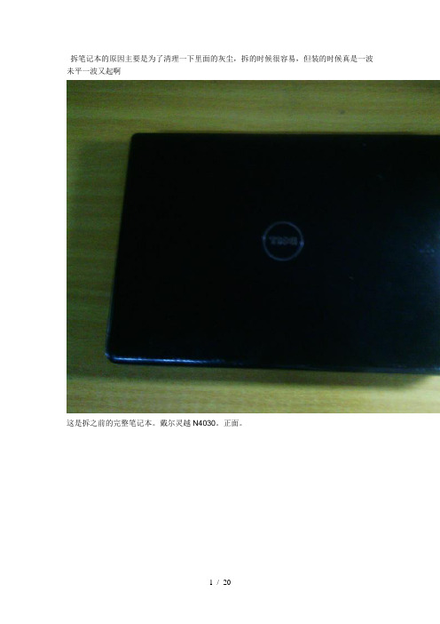
拆笔记本的原因主要是为了清理一下里面的灰尘,拆的时候很容易,但装的时候真是一波未平一波又起啊
这是拆之前的完整笔记本。
戴尔灵越N4030。
正面。
这是背面。
先把电池和一个后盖打开。
很简单。
把最大的后盖一并掀开,就是这个样子。
不过一定要保存好螺丝,还要清楚的记得你拆的每个零件的位置,别一会你不知道怎么装上去。
把键盘掀开,键盘上没有螺丝,只有一些暗扣。
把暗扣轻轻叩开,不要损伤。
这是拆的很彻底的一张图。
把屏幕和主机完全分离,,,当时看着这一堆乱杂杂的零件,真怕自己一会装不回去。
这是电池。
完整的主板,,,,,,,,看着复杂的电路,真佩服设计电脑的人,电路图,PCB制作,组装,,,,真是厉害。
准备把这个主板给掀开。
这是风扇,风扇上会有好多灰,拆笔记本主要就是为了清洗它。
拍个照一遍,记住他们的位置,省的一会忘了。
把主板掀开了,,,,,,就是这个样子了,不用再卸了。
可以清理了
这是卸的最彻底的一张图,,,,,,,,,
这根大荒黄线一定不要动,动了你就死定了。
前晾干,,,,用吹风机吹也可以。
清洗风扇。
清洁套装里面的小刷子很有用额。
这是卸下来的键盘,,,,当时想的是,,这该怎么装回去呢、
不拆你不知道有多少灰,这是清洗过之后的纸。
N3000系列产品参数对照表
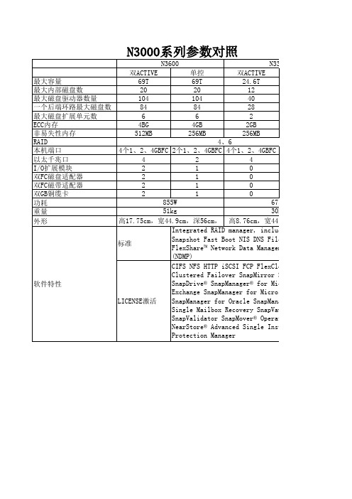
N3600 最大容量 最大内部磁盘数 最大磁盘驱动器数量 一个后端环路最大磁盘数 最大磁盘扩展单元数 ECC内存 非易失性内存 RAID 本机端口 以太千兆口 I/O扩展模块 双FC磁盘适配器 双FC磁带适配器 双GB铜缆卡 功耗 重量 外形 双ACTIVE 69T 20 104 84 6 4BG 512MB 单控 69T 20 104 84 6 4GB 256MB 双ACTIVE 24.6T 12 40 28 2 2GB 256MB N3300
N3300 单控 24.6T 12 40 28 2 2GB 128MB
2个1、2、4GBFC 2 0 0 0 0 675W 30kg .9cm,深56cm, er, including RAID-DP S DNS FilerView® FlexVol ta Management Protocol
CP FlexClone MultiStore SnapRestore r® for Microsoft for Microsoft SQL Server e SnapManager for SAP ry SnapVault er® Operations Manager ingle Instance Storage
软件特性
4、6 4个1、2、4GBFC 2个1、2、4GBFC 4个1、2、4GBFC 4 2 4 2 1 0 2 1 0 2 1 0 2 1 0 855W 675W 51kg 30kg 高17.75cm,宽44.9cm,深56cm, 高8.76cm,宽44. Integrated RAID manager, including RAID-DP Snapshot Fast Boot NIS DNS FilerView® FlexVol 标准 FlexShare™ Network Data Management Protocol (NDMP) CIFS NFS HTTP iSCSI FCP FlexClone MultiStore Clustered Failover SnapMirror SnapRestore SnapDrive® SnapManager® for Microsoft Exchange SnapManager for Microsoft SQL Server SnapManager for Oracle SnapManager for SAP LICENSE激活 Single Mailbox Recovery SnapVault SnapValidator SnapMover® Operations Manager NearStore® Advanced Single Instance Storage Protection Manager
BT官方已测试网卡列表

USB接口的无线网卡:Airlink101 AWLL3026驱动 : zydas芯片组: zd1211rw很好的USB卡.不贵,<10美元). 完全兼容注入.ALFA Networks AWUS036H驱动 : rtl8187芯片组 : Realtek 8187BackTrack2下包括注入都能完美工作ASUS WL-167G驱动 : rt73 (older version rt2570)芯片组 : rt2571WF (older verson Ralink 2570)范围较小但是监控和注入都能完美工作. 注入很慢.AVM Fritz!Wlan USB V1.1驱动 : ndiswrapper芯片组 :Texas Instrument TNetW1450注意: NdisWrapper不能正常运行Aircrack-ngBelkin F5D7050 V1驱动 : rt2570芯片组 : rt2571F本来很好,一段时间后不能进入监控模式了注意:以后有版本采用bcm43xx芯片组!Belkin F5D7050 (4000 series)驱动 : zd1211rw芯片组 : zd1211b本来只能监控不能注入,然而,打过补丁包括注入一切都能完美运行.Belkin F5D7050B驱动 : rt73芯片组: Ralink 2570包括注入都能正常工作.Belkin F5D7051驱动 : ??芯片组: bcm4320明显的,贝尔金改变了芯片组,用bcm4320芯片组代替了ra2570.bcm4320驱动,不能正常工作了.Buffalo Airstation G54 WLI-U2-KG54-AI (2A)驱动 : rt2570芯片组 : Ralink 2570Chiefmax驱动 : RT73芯片组 : rt2571WFD-Link DWL 122 (USB) F/W 3.2.1 H/W A1驱动 : wlan-ng芯片组 : prism 2.5注意 : 注入不能正常工作因为软件不支持,不过如果降级到2.4核心的Linux就能正常工作.D-Link DWL G122 (USB) F/W 2.03 B1驱动 : rt2570芯片组 : Ralink 2570搜索能力真的很差。
Teledyne LeCroy发布RP4030电源探头和MIPI SPMI解码软件
I S L 9 9 2 2 7 ) 。这些新型数字控制器提供多达七个相
位, 可按 任 意组 合分 配到 两个 输 出 , 与智 能功 率级 相 结 合 可 以提 供从 1 0 A至 4 5 0 A 的可 扩 展 解 决 方 案 ,
T e I e d y n e L e C r o y发布 R P 4 0 3 0
S P M I 解码软件会监测并且将 S P M I 总线消息和 D C
电压 的变化 联 系起来 ,这两 个产 品非 常适 合测试 交 流或 者 电池供 电 的产 品 , 以及 采用 数 字 电源 管 理 I C ( P MI C) 降低 功耗 、 提 高效 率 的嵌 入式 系 统 , 这 两款 产 品扩展 了 T e l e d y n e L e c r o y已 有 的 H D O 8 1 0 8
它 产 品 的利 润 , 这 些 产 品包 括 该 公 司 自己 的 E x y n o s
S i l i c o n L a b s 针对 I o T终 端 节 点 推 出全 球 最 小尺 寸 的蓝 牙 S i P模 块
芯科 科 技 ( S i l i c o n L a b s )1 3前 推 出 业 界 最 小 尺 寸 m 的低 功耗 蓝 牙 ( B l u e t o o t h  ̄l o w e n e r g y) 系统 级封装 ( s y s t e m— i n — p a c k a g e , S i P) 模块, 其 内置 芯 片 型天 线 , 提供 完整 的低 成 本连 接解 决方 案 , 且不 影 响 性 能 。B G M1 2 x B l u e G e c k o S i P模 块 采 用 小 巧 的
从而增强功率优化 ,提高网络和通信基础设施设备
AUTODOME 4000 NDA-4020-PIP 接口挂件 - 布朗安全商品说明书
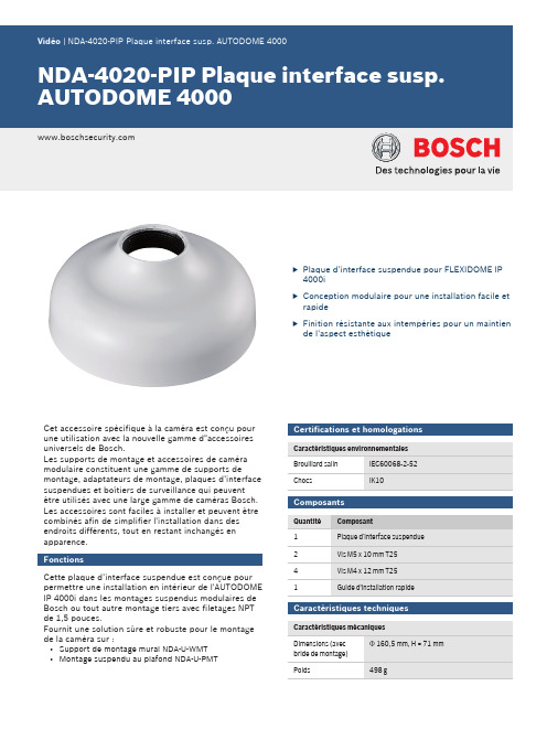
uPlaque d’interface suspendue pour FLEXIDOME IP 4000iuConception modulaire pour une installation facile et rapideuFinition résistante aux intempéries pour un maintien de l'aspect esthétiqueCet accessoire spécifique à la caméra est conçu pour une utilisation avec la nouvelle gamme d"accessoires universels de Bosch.Les supports de montage et accessoires de caméra modulaire constituent une gamme de supports demontage, adaptateurs de montage, plaques d’interface suspendues et boîtiers de surveillance qui peuvent être utilisés avec une large gamme de caméras Bosch.Les accessoires sont faciles à installer et peuvent être combinés afin de simplifier l'installation dans des endroits différents, tout en restant inchangés en apparence.FonctionsCette plaque d’interface suspendue est conçue pour permettre une installation en intérieur de l'AUTODOME IP 4000i dans les montages suspendus modulaires de Bosch ou tout autre montage tiers avec filetages NPT de 1,5 pouces.Fournit une solution sûre et robuste pour le montage de la caméra sur :•Support de montage mural NDA-U-WMT •Montage suspendu au plafond NDA-U-PMTCertifications et homologationsComposantsCaractéristiques techniquesPlaque d’interface suspendue NDA-4020-PIP Dimensions en mmInformations de commandeNDA-4020-PIP Plaque interface susp. AUTODOME 4000 Plaque d'interface suspendue pour AUTODOME IP 4000i.Numéro de commande NDA-4020-PIPAccessoiresNDA-U-PMT Montage suspendu plafond 31cm Montage sur tube universel pour caméras dôme,31 cm, blancNuméro de commande NDA-U-PMTNDA-U-PMTE Extension pour suspension 50cm Extension pour montage sur tube universel, 50 cm, blancNuméro de commande NDA-U-PMTENDA-U-WMT Montage mural suspenduMontage mural universel pour les caméras dôme, blanc Numéro de commande NDA-U-WMT2Représenté par :Europe, Middle East, Africa:Germany:Bosch Security Systems B.V.P.O. Box 800025600 JB Eindhoven, The Netherlands Phone: + 31 40 2577 284****************************** Bosch Sicherheitssysteme GmbH Robert-Bosch-Ring 585630 GrasbrunnGermany© Bosch Security Systems 2017 | Les données sont susceptibles d'être modifiées sans notification préalable. 23065136779 | fr, V5, 18. Oct 2017。
KDS USB FW Update User Manual
111-38-URM-011KDS USB FW UpdateUser ManualKDS USB FW Update 111-38-URM-011Table of Contents1. Introduction (3)2. Process under Microsoft Windows (4)3. Process under Mac OS (5)KDS USB FW Update 111-38-URM-0111. IntroductionThe Epson Kitchen Display System (henceforth KDS) is preferably updated using the KDS Utility. However, an alternate update method using a USB flash drive can be employed as fallback if required, and is typically faster than with the KDS Utility, albeit at the cost of losing any configuration from the KDs device. This document describes the typical process to set up a USB flash drive for the firmware update.The same firmware update process is used for printers and controllers (henceforth called display box). Once set up, the USB flash drive can be used to sequentially update multiple devices.IMPORTANT NOTES:i. Before you proceed, note that updating the KDS using this method erases allconfiguration from the target device(s). The KDS Utility may be used to re-configure the system.ii. There are certain flash drives that may not work with this method and would fail the update process verification step in the procedures. Some models tested include:a. Kingston DataTraveler 8GB/16GBb. Transcend JetFlash V70 16GBc. Axiom Stealth 2 USBFD2 2GBd. SanDisk Cruzer Dial USB 16GBe. Misc. brands like AData, Samsung, Verbatim, Sony etc. USB 2.0 flash drivesKDS USB FW Update 111-38-URM-0112. Process under Microsoft WindowsThe following process has been verified under Microsoft Windows 7 and Windows 10. Most failures with the method can be attributed to user permissions (inability to modify USB flash drive) incompatible or corrupted USB flash drives.Here are the basic instructions for flashing the printer/display box FW:1. Get a USB flash drive of 1GB or more with no contents you care about, as everything on it will beerased.2. Plug the USB flash drive into a Windows PC.3. Run dd_win.exe (provided in the firmware update package)o Click on “File select…” and browse to the file “usb_boot_image_v26.ubi”o Click on “Drive select…” and specify the drive letter of the USB sticko Hit 'Run' and wait until completed.4. ***IMPORTANT*** Safely eject the USB flash drive from Windows, then unplug it, wait a fewseconds, then plug it back in again.5. Unzip the “KDS Image.zip” file onto the USB flash drive. The final layout of the USB stick should be:\|- autooperation|- uImage|- BOOT.BIN|- images\|-- control.tar.gz|-- hibdrv|-- hibernation|-- hibernationinfo|-- rootfs|-- uImage|-- writable-region6. Eject the USB stick from the PC again.7. Label the USB stick with ‘KDS Image’ to indicate what image is on it in case it is requ ired for otherdisplay boxes/printers or in future.Follow these instructions for each printer/display box that needs to be updated:1. With the printer/display box turned off, plug the USB flash drive into the Interface card at the back.2. Use a pen or paper clip to press the button on the BACK of the printer/display box, and keep itpressed while turning the board on. Keep holding the button down for three or four seconds until the LED near the button goes out.3. The LED light will then show orange for about 45 seconds, and then green for about 5 seconds, thenflash orange for about 60 seconds. Once the FW update is complete, the LED will flash green.4. Turn off the printer.5. Remove the USB flash drive from the back.6. Turn the printer/display box back on and wait for it to boot up; the LED on the back turns solid green.The KDS splash screen will show the new FW version on the attached monitor.7. The system should be ready to go.KDS USB FW Update 111-38-URM-0113. Process under Mac OSThe following process has been verified under Mac OS 10 and 11. Most failures with the method can be attributed to user permissions (inability to modify USB flash drive) incompatible or corrupted USB flash drives.Here are the basic instructions for flashing the printer/display box FW:1. Save the firmware update package (which includes the file usb_boot_image_v26.ubi) in the Desktopor Downloads folder.2. Get a USB flash drive of 1GB or more with no contents you care about, as everything on it will beerased. Do NOT plug it in yet.3. On the Mac, open a new terminal (iTerm).4. Type the command “diskutil list”to get the current list of devices.5. Now plug the USB flash drive into the Mac.6. Type the command “diskutil list”again and note the additional device, which is the USB flashdrive (e.g. /dev/disk2).7. Type the command “diskutil unmountDisk /dev/diskX”, where X is the number from Step 5.8. Type the following command:sudo dd if=$(find ~ -name usb_boot_image_v26.ubi | head -n 1) of=/dev/diskX bs=1m(again, substitute the X in the command with the number you learned from Step 5.)Please note:i. The command above will ask for the user (or administrator) password once; this is normal.ii. The command, when run for the first time, will trigger several pop-up dialogs requesting access to some folders. See Figure 3.1.iii. The command will output several lines with the text “Operation not permitted” when trying to search certain inaccessible folders; this is normal.Figure 3.1: Mac OS pop-ups requesting user permission to access some folders.(c ontinued…)KDS USB FW Update 111-38-URM-0119. ***IMPORTANT*** Safely eject the USB stick from the Mac, then unplug it, wait a fewseconds, then plug it back in again.10. Unzip the KDS Image.zip file into USB stick. This means the final layout for the USB stick should be:\|- autooperation|- uImage|- BOOT.BIN|- images\|-- control.tar.gz|-- hibdrv|-- hibernation|-- hibernationinfo|-- rootfs|-- uImage|-- writable-region11. Eject the USB stick from the Mac again.12. Label the USB stick with ‘KDS Image’ to indicate what image is on it in case it is required for otherdisplay boxes/printers or in future.Follow these instructions for each printer/display box that needs to be updated:1. With the printer/display box turned off, plug the USB flash drive into the Interface card at the back.2. Use a pen or paper clip to press the button on the BACK of the printer/display box, and keep itpressed while turning the board on. Keep holding the button down for three or four seconds until the LED near the button goes out.3. The LED light will then show orange for about 45 seconds, and then green for about 5 seconds, thenflash orange for about 60 seconds. Once the FW update is complete, the LED will flash green.4. Turn off the printer.5. Remove the USB flash drive from the back.6. Turn the printer/display box back on and wait for it to boot up; the LED on the back turns solid green.The KDS splash screen will show the new FW version on the attached monitor.7. The system should be ready to go.KDS USB FW Update 111-38-URM-011This page intentionally left blank.KDS USB FW Update 111-38-URM-011。
WNA1100 N150无线USB适配器安装指南说明书
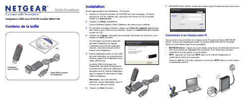
Guide d'installation Adaptateur USB sans fil N150 modèle WNA1100Contenu de la boîteCD InstallationDurée approximative de l'installation : 10 minutes.1. Insérez le CD dans le lecteur de CD-ROM de votre ordinateur. Si l'écranprincipal du CD ne s'affiche pas, parcourez les fichiers du CD et double-cliquez sur Autorun.exe.2. Cliquez sur Setup (Installation).L'écran Software Update Check (Détection de mises à jour) s'affiche.3. Si vous êtes connecté à Internet, cliquez sur Check for Updates (Rechercherdes mises à jour). Dans le cas contraire, cliquez sur Install from CD (Installerà partir du CD).4. Cliquez sur I Agree (J'accepte) pour accepter les termes de la licence, puiscliquez sur Next (Suivant).pendant l'installation du logiciel.L'opération peut prendre quelquesinsérer votre adaptateur.5.câble USB fournis.Le câble USB et le support deUSB à l'ordinateur.Remarque : pour des résultatsà moins un mètre du routeur.6. Cliquez sur Next(Suivant).7. NETGEAR Genie affiche la liste des réseaux sans fil présents dans votre zone.Connexion à un réseau sans filVous pouvez vous connecter à un réseau sans fil à partir de l'écran NETGEARGenie. Vous pouvez également utiliser la fonctionnalité WPS (Wi-Fi ProtectedSetup) si votre réseau sans fil est compatible.• NETGEAR Genie : cliquez sur votre réseau sans fil pour le sélectionner dans laliste, puis cliquez sur Connect (Se connecter). Si le réseau est sécurisé,saisissez le mot de passe ou la clé réseau.• WPS : appuyez sur le bouton WPS situé sur le côté de l'adaptateur etmaintenez-le enfoncé 2 secondes.Dans un délai de 2 minutes, appuyez sur le bouton WPS situé sur votre routeurMai 2011Ce symbole a été apposé conformément à la directive européenne 2002/96 sur la mise au rebut des équipements électriques et électroniques (directive WEEE - Waste Electrical and ElectronicEquipment). En cas de mise au rebut de ce produit dans un Etat membre de l'Union européenne, il doit être traité et recyclé conformément à cette directive.©2011 par NETGEAR, Inc. Tous droits réservés. NETGEAR et le logo NETGEAR sont des marques déposées de NETGEAR, Inc. aux Etats-Unis et/ou dans d'autres pays. Les autres marques ou noms de produits sont des marques commerciales ou des marques déposées de leurs détenteurs respectifs. Ces informations sontsusceptibles d'être modifiées sans préavis.L'adaptateur se connecte au réseau (l'opération peut prendre plusieurs minutes). Vos paramètres sont enregistrés dans un profil.Icône NETGEAR GenieLorsque vous installez votre adaptateur, l'icône NETGEAR Genie s'affiche dans la zone de notification Windows et sur le bureau. Cliquez sur cette icône pour ouvrir NETGEAR Genie et apporter des modifications ou établir une connexion vers un autre réseau sans fil. La couleur de l'icône indique le niveau de puissance de votre connexion sans fil, de zéro à cinq barres.Vert : 3 à 5 barres Jaune : 1 ou 2 barresRouge : 0 (zéro) barre, aucune connexionSi vous retirez l'adaptateur, NETGEAR Genie n'est pas disponible et l'icône ne s'affiche pas. Elle s'affiche à nouveau si vous réinsérez l'adaptateur.Assistance techniqueNous vous remercions d'avoir choisi les produits NETGEAR.Après l'installation de votre périphérique, notez le numéro de série inscrit surl'étiquette de votre produit. Il vous sera nécessaire pour enregistrer votre produit à l'adresse gear.fr/support/. Vous devez être enregistré pour utiliser le service d'assistance téléphonique. Nous vous recommandons vivement de procéder à l'enregistrement sur le site Web NETGEAR.Visitez le site gear.fr/support/ pour obtenir des mises à jour de produits et consulter le support Web.Pour en savoir plus sur l'installation, la configuration et l'utilisation de votre adaptateur USB sans fil, reportez-vous au Manuel de l'utilisateur .Pour consulter la déclaration de conformité complète, rendez-vous sur le site Web NETGEAR des déclarations de conformité pour l'UE à l'adresse : /app/answers/detail/a_id/11621/.Pour obtenir des informations sur la licence publique générale GNU (GPL),rendez-vous à l'adresse : /app/answers/detail/a_id/2649.。
基聆耳听 4030C 操作指南说明书

4030COperating ManualGeneralThe bi-amplified Genelec 4030C is an extremely compact two way active loudspeaker designed for fixed installations. As an active loudspeaker, it contains drivers, power amplifiers, active crossoverfilters and protection circuitry. The 4030C is designed for indoor use only, in temperatures between 15 to 35 degrees Celsius and relative humidity between 20 % and 90 %.The MDE™ (Minimum Diffraction Enclosure™) loudspeaker enclosure is made of die-cast aluminium and shaped to reduce edge diffraction. Combined with the advanced Directivity Control Waveguide TM (DCW TM), this design provides excellent frequency balance in difficult acoustic environments.Positioning the loudspeaker Each 4030C is supplied with an integrated amplifier unit, mains cable, a 3-pin balanced Euroblock connector for audio signal, a keyhole type wallmount and an operating manual. After unpacking, place the loudspeaker in its required listening position, taking note of the line of the acoustic axis. The axis should be pointed towards the center of the listening area.ConnectionsBefore connecting up, ensure that the loudspeakers and the signal source have been switched off. The power switch of the 4030C is located on the back panel (see Figure 3). Connect the loudspeaker to an earthed mains connection with the supplied mains cable. Never connect the loudspeaker to an unearthed mains supply or using an unearthed mains cable. Audio input is via a 10 kOhm balanced connector. The pin sequence of the connector is shown in Figure 2.Connect the signal cable to the 3-pole plug provided with the loudspeaker and secure the connections by tightening the screws on each pole. Push the plug into the connector on the loudspeaker.If you want to daisy-chain multiple loudspeakers, simply connect a second signal cable to the plug and use it to route the signal to the next loudspeaker (see Figure 4).Never connect the 4030C to the loudspeaker outputs of a power amplifier or an integrated amplifier or receiver.Once the connections have been made, the loudspeakers are ready to be switched on.ISS TM AutostartThe automatic power saving function ISS (Intelligent Signal Sensing) can be activated by setting the “ISS” switch on the back panel to “ON.” Automatic powering down to standby mode happens after a certain time when playback has ended. The power consumption in standby mode is typically less than 0.5 watts. Playback will automatically resume once an input signal is detected from the source. There is a slight delay in the automatic powering up. If this is undesirable, the ISS TM function can be disabled by setting the “ISS” switch on the back panel to “OFF.” In this mode, the loudspeaker is powered on and off using the power switch on the back panel.4030CActive Loudspeaker2Level controlThe input sensitivity of the loudspeaker can be matched to the output of the signal source by adjusting the level control on the rear panel.Setting the tone controlsThe frequency response of the Genelec 4030C can be adjusted to match the acoustic environment by setting the tone control switches on the rear panel. The controls are “Treble Tilt”, “Bass Tilt” and “Bass Roll-Off”. An acoustic measuring system such as WinMLS or comparable is recommended for analyzing the effects of the adjustments, however, careful listening with suitable test recordings can also lead to good results if a test system is not available. Table 1 shows some examples of typical settings in various situations. Figure 4 shows the effect of the controls on the anechoic response.Treble TiltThe Treble Tilt control (switch 1) boosts the treble response of the loudspeaker at frequencies above 5 kHz by +2 dB, which can be used for compensating for the high frequency loss at long distance. Bass TiltThe Bass Tilt control offers three attenuation levels for the bass response of the loudspeaker below 2 kHz, usually necessary when the loudspeakers are placed near a wall or other room boundaries.Figure 2: Audio input pin sequence+NON-INVERTING–INVERTINGGNDGROUND+–GNDFigure 4: Cable connection for daisy-chaining speakers34The attenuation levels are -2 dB (switch 3 “ON”), -4 dB (switch 4 “ON”) and -6 dB (both switches “ON”).Bass Roll-OffBass Roll-Off (switch 3) activates a -4 dB filter to the lowest bass frequencies (55 Hz). This can be used for compensating excessively heavy bass reproduction typically caused by loudspeaker placement near room boundaries.The factory setting for all tone controls is “OFF” to give a flat anechoic response. Always start adjustment by setting all switches to “OFF” position. Measure or listen systematically through the different combinations of settings to find the best frequency balance.Mounting considerationsAlign the loudspeakers correctlyAlways place the loudspeakers so that their acoustic axes (see figure 1) are aimed towards the center of the listening area. Only vertical placement is preferred, as it minimises acoustical cancellation problems around the crossover frequency.Minimise reflectionsAcoustic reflections from objects close to the loudspeakers like walls, cabinets etc. can cause unwanted colouration blurring of the sound image. These can be minimised by placing the loudspeaker clear of reflective surfaces.Minimum clearancesSufficient clearance for cooling of the amplifier and functioning of the reflex port must be ensured if the loudspeaker is installed in a restricted space such as a cabinet or integrated into a wall structure. The surroundings of the loudspeaker must always be open to the listening room with a minimum clearance of 3 centimeters (13/16”) behind, above and on both sides of the loudspeaker. The space adjacent to the amplifier must either be ventilated or sufficiently large to dissipate heat so that the ambient temperature does not rise above 35 degrees Celsius (95°F)Mounting optionsThe Genelec 4030C offers several mounting options: On the base of the loudspeaker is a 3/8” UNC threaded hole compatible with a standard microphone stand. On the rear there are two M6x10 mm threaded holesTable 1: Suggested tone control settings for differing acoustical environmentsLoudspeaker Mounting Position Treble Tilt Bass Tilt Bass Roll-OffFlat anechoic responseOFF OFF OFF Free standing in a damped room OFF OFF OFF Free standing in a reverberant room OFF -2 dB OFF Near field or desktop OFF -4 dB OFF Near to a wallOFF-6 dBOFFfor Omnimount®size 20.5 brackets or the keyhole wall mount adapter provided with the loudspeaker. See Genelec Accessories Catalogue on for a complete list of mounting hardware options.MaintenanceNo user serviceable parts are to be found within the amplifier unit. Any maintenance or repair of the 4030C unit should only be undertaken by qualified service personnel.Safety considerations Although the 4030C has been designed in accordance with international safety standards, the following warnings and cautions should be observed to ensure safe operation and to maintain the loudspeaker under safe operating conditions:• Servicing and adjustment must only be performed by qualified service personnel.The loudspeaker must not be opened.• Do not use this product with an unearthed mains cable or an unearthed mains connection as this may compromise electrical safety.• Do not expose the loudspeaker to water or moisture. Do not place any objects filled with liquid, such as vases on the loudspeaker or near it.• This loudspeaker is capable of producing sound pressure levels in excess of 85 dB, which may cause permanent hearing damage.• Free flow of air behind the loudspeaker is necessary to maintain sufficient cooling.Do not obstruct airflow around theloudspeaker.• Note that the amplifier is not completely disconnected from the AC mains service unless the mains p ower cord is removed from the amplifier or the mains outlet.GuaranteeThis product is guaranteed for a period of two years against faults in materials or workmanship. Refer to supplier for full sales and guarantee terms.Compliance to FCC rulesThis device complies with part 15 of the FCC Rules. Operation is subject to the following conditions:• This device may not cause harmful interference, and • This device must accept any interference received, including interference that may cause undesired operation. Note: This equipment has been tested and found to comply with the limits for a Class B digital device, pursuant to part 15 of the FCC Rules. These limits are designed to provide reasonable protection against harmful interference in a residential installation. This equipment generates, uses and can radiate radio frequency energy and, if not installed and used in accordance with the instructions, may cause harmful interference to radio communications. However, there is no guarantee that interference will not occur in a particular installation. If this equipment does cause harmful interference to radio or television reception, which can be determined by turning the equipment off and on, the user is encouraged to try to correct the interference by one or more of the following measures:• Reorient or relocate the receiving antenna.• Increase the separation between the equipment and receiver.• Connect the equipment into an outlet on a circuit different from that to which the receiver is connected.• Consult the dealer or an experienced radio/TV technician for help.Modifications not expressly approved by the manufacturer could void the user’s authority to operate the equipment under FCC rules.567AMPLIFIER SECTIONBass amplifier output power: 50 W Treble amplifier output power:50 WLong term output power is limited by driver unit protection circuitry.Amplifier system distortion at nominal output: THD < 0.05 % Mains voltage: 100-240 V AC 50-60 HzVoltage operating range: ±10 %Power consumption: Idle3 W Standby (ISS active) <0.5 W Full output60 W SYSTEM SPECIFICATIONSLower cut-off frequency, –6 dB: < 47 Hz Upper cut-off frequency, –6 dB:> 25 kHzAccuracy of frequency response: 54 Hz – 20 kHz (± 2.0 dB)Maximum short term sine wave acoustic output on axis in half space, averaged from 100 Hz to 3 kHz: @ 1 m > 104 dB SPLMaximum long term RMS acoustic output in sameconditions with IEC weighted noise (limited by driver unit protection circuit): @ 1 m > 96 dB SPL Maximum peak acoustic output per pair @ 1 m distance with music material: > 110 dB Self generated noise level in free field @ 1m on axis: < 5 dB (A-weighted)Harmonic distortion at 85 dB SPL @ 1m on axis:Freq: 50…100 Hz < 2 % >100 Hz < 0.5 %Drivers: Bass 130 mm (5 in ) coneTreble 19 mm (3/4 in ) metal domeWeight: 4.9 kg (10.8 lb)Dimensions: Height 285 mm (111/4 in )Width 189 mm (77/16 in )Depth178 mm (71/16 in )CROSSOVER SECTIONInput connector: Balanced 10 kOhm 3 pin EuroblockInput level for 100 dB SPL output at 1 m: -6 dBuLevel control range:-40 dB constantly variableCrossover frequency, Bass/Treble:3.0 kHzTreble Tilt control operating range: 0 to +2 dB @ 15 kHz Bass Roll-Off control:–4 dB @ 55 HzBass Tilt control operating range in –2 dB steps: 0 to –6 dB @ 100 Hz The ‘CAL’ position is with all tone controls set to ‘off’ and the level control to maximum (fully clockwise).Genelec Document D0091R001d. Copyright Genelec Oy 2.2017. All data subject to change without prior noticeInternational enquiriesGenelec, Olvitie 5FI 74100, Iisalmi, Finland Phone +358 17 83881Fax +358 17 812 267************************In SwedenGenelec Sverige Ellipsvägen 10B P .O. Box 5521, S-141 05 Huddinge Phone +46 8 449 5220Fax +46 8 708 7071*********************In the USAGenelec, Inc., 7 Tech Circle Natick, MA 01760, USA Phone +1 508 652 0900Fax +1 508 652 0909****************************In ChinaBeijing Genelec Audio Co.Ltd Room 101, 1st Floor Building 71 B33Universal Business Park No. 10 Jiuxianquiao Road Chaoyang District Beijing 100015, ChinaPhone +86 010 5869 7915/13******************************。
Sennheiser SC 40 USB MS BLACK 单耳穿戴耳机说明说明书

Libérez votrepotentielSérie Culture PlusSC 40 USB MS BLACKSC 40 USB MS BLACKLibérez votre potentielLe SC 40 USB MS BLACK Sennheiser est un micro-casque filaire monaural pour lesprofessionnels utilisant Skype Entreprise dans les bureaux et les entreprises. Avec son adaptation instantanée, son excellente sonorité et ses lignes épurées, il permet de passer plus facilement d'un systèmetraditionnel à des communications unifiées pour exploiter tout le potentiel de votre nouvelle culture de communication.La maîtrise du sonAvec la clarté de voix Sennheiser et unmicrophone anti-bruit, le SC 40 USB MS BLACK optimise l'intelligibilité de la parole dans les environnements bruyants pour fournir aux deux interlocuteurs une expérience plus naturelle de la conversation pendant les appels. Les profils d'amélioration du sonprocèdent automatiquement aux ajustements optimisant la communication ou l'utilisation multimédia.Un design de qualitéAvec son style moderne, le SC 40 USB MS BLACK est du plus bel effet, que ce soit à l’accueil ou pour des appels par Skype. L’arceau ultraléger avec rembourrage en similicuir se courbe et s'ajuste pour unmaintien personnalisé tandis que la perchette souple positionne parfaitement le microphone.L'utilisateur avant toutAvec ses possibilités d'ajustement instantané et son choix de coussinet d'oreille en mousse acoustique ou recouvert de similicuir doux, le SC 40 USB MS BLACK procure immédiatement un confort supérieur aux utilisateurs.Il bénéficie d’une télécommande intégrée au câble pour une gestion transparente des appels et de la technologie ActiveGard®Sennheiser pour protéger les utilisateurs des chocs acoustiques. Une pochette pour le transport ou le rangement protège le micro-casque quand on ne l’utilise pas.Caractéristiques et avantages : C ertifié pour Skype Entreprise – avec gestion des appels par télécommande intégrée et connecteur USB C larté de voix Sennheiser – son large bande pour une expérience d'écoute naturelle M icrophone anti-bruit – filtre le bruit ambiant pour une clarté optimale de la parole D esign contemporain original – pour l'élégance et l’ergonomieC onfort instantané – l'arceau flexible avec rembourrage en similicuir s'ajuste pour un maintien parfait 2 styles de coussinets d'oreille en 1– choisissez entre similicuir doux ou mousse acoustique légère pour un confort maximal O ptimisé pour la communication et le multimédia – avec profils d'amélioration sonore automatique T élécommande intégrée au câble – simple et fonctionnelle pour une gestion facile des appels P erchette souple – assure une position optimale du microphone L a technologie ActiveGard® de Sennheiser protège les utilisateurs des chocs acoustiques. H ousse de protection – pour faciliter le rangement et le transport L imiteur « Bruit au travail » commutable – en conformité avec la Directive sur le bruit au travail (2003/10/CE) de l'UE.Informations produitSC 40 USB MS BLACK50649840 44155 20692 06 15104 27016 9Données généralesMicrophoneHaut-parleurTélécommandeConditionnementContenu de l'emballagePièces de rechange50650940 44155 20743 9 6 15104 27083 150651240 44155 20746 0 6 15104 27088 650651340 44155 20747 7 6 15104 27089 3 Garantie/ccocommunications unifiées./ccoMAÎTRISE DU SONL’UTILISATEUR AVANT TOUTDESIGN DE QUALITÉFAITES L’EXPÉRIENCE。
戴尔 灵越N4030 官方拆机图解维修
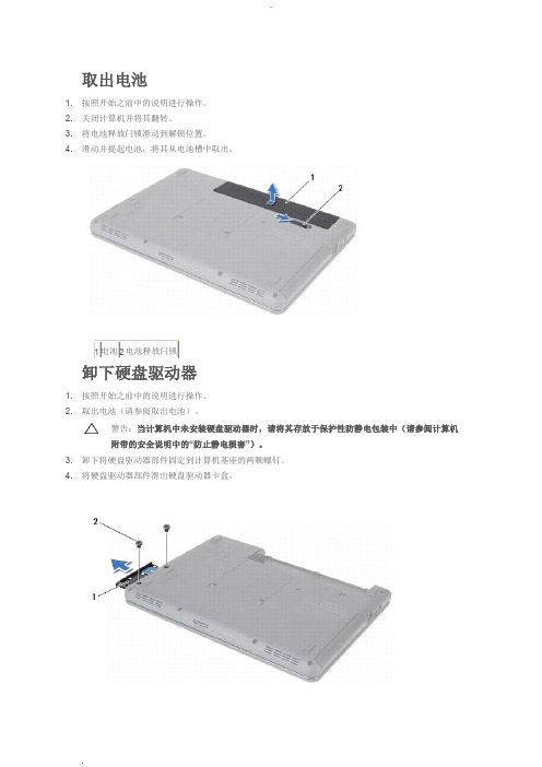
3. 将电池释放闩锁滑动到解锁位置。
4. 滑动并提起电池,将其从电池槽中取出。
取出电池(请参阅取出电池)。
警告:附带的安全说明中的3. 卸下将模块护盖固定至计算机基座的螺钉。
4. 使用计算机基座上的槽口提起并滑动模块护盖卡舌,将其从计算机基座上的插槽中取出。
卸下模块护盖(请参阅卸下模块护盖)。
警告:4. 请用指尖小心拨开内存模块连接器两端的固定夹,直至模块弹起。
5. 从内存模块连接器中卸下内存模块。
7. 卸下将键盘固定至计算机基座的两颗螺钉。
翻转计算机,并把显示屏打开到最大程度。
警告:小心操作。
9. 按住键盘并向下滑动键盘。
10. 滑动键盘与掌垫之间的塑料划片,撬起并提起键盘,使其脱离掌垫上的卡舌。
警告:卸下键盘(请参阅卸下键盘)。
警告:些电缆的连接器带有锁定卡舌;如果要断开此类电缆的连接,请先向内按压锁定卡舌,然后再断开电缆的连接。
在拔出连接器的过程中,请保持两边对齐以避免弄弯任何连接器插针。
另外,在连接电缆之前,请确保两个连接器的朝向正确并对齐。
8. 断开天线电缆与小型插卡的连接。
9. 卸下将小型插卡固定至I/O 板上的连接器的螺钉。
10. 提起小型插卡,将其从I/O 板连接器中取出。
6. 卸下内存模块(请参阅卸下内存模块)。
7. 卸下将掌垫固定至计算机基座的六颗螺钉。
警告:卸下掌垫上的五颗螺钉。
警告:11. 从掌垫的右/左侧开始,使用手指将掌垫与计算机基座分开。
12. 将掌垫提离计算机基座。
卸下将电源按钮板固定至掌垫的螺钉。
注:电源按钮板电缆粘附在掌垫上。
12. 将电源按钮板提离掌垫。
12. 从计算机基座中提起显示屏部件并将其卸下。
卸下显示屏挡板警告:4. 用指尖小心地撬起显示屏挡板的内边缘。
5. 卸下显示屏挡板。
4. 断开摄像头电缆与摄像头模块上连接器的连接。
5. 卸下将显示屏面板固定至显示屏护盖的六颗螺钉。
拨开将显示屏电缆固定至显示屏板连接器的胶带,然后断开显示屏电缆的连接。
注:摄像头电缆粘附在显示屏面板的背面。
夜間雲端無線網路攝影機 IC-3140W 產品說明说明书

IC-3140WH.264夜間雲端無線網路攝影機產品資訊1-1 包裝內容IC-3140W安裝指南CD電源變壓器 網路線 壁掛安裝組件1-2 前面板麥克風PIR 人體紅外線感應器LED 指示燈紅外線LED 燈可調焦鏡頭 光線感應器1-3 背板1-4 LED 指示燈MAC/Cloud ID 及Setup SSID LAN 埠12V DC 電源連接埠WPS/Reset 按鍵MicroSD 卡插槽喇叭1-5背板標籤貼紙本產品背面貼有著標籤貼紙,貼紙上印有MAC位址、Cloud ID及Setup SSID 等資訊。
為方便對照使用,本產品的Mac 位址與Cloud ID是一樣的。
Cloud ID是為了讓您可以遠端觀看本產品所拍攝的即時影像時使用。
硬體安裝壁掛安裝組件安裝本產品可站立擺放也可搭配附贈的基座做壁掛式安裝。
1.組裝壁掛基座方式如下圖示:2.將壁掛基座上的螺絲頭栓入本產品背板上的螺絲孔如您家中有三角架,您也可以將本產品安裝在其上使用攝影機本體安裝請按照下面的說明以確保您的攝影機已正確連接並安裝就緒。
1.請將電源變壓器連接至本產品背板下方的電源連接埠,並將插頭端插入電源插座。
2.請稍待本產品開機完成。
在開機過程中,機器本身會發出一些聲音,這是正常的現象,並且當它開機完成時,綠色的電源LED燈號會呈現慢速閃爍的狀態。
設定本產品須使用有線連網方式進行(請參照操作手冊說明)。
3.請使用您的手機或平板,依您其作業系統至Google Play或Apple AppStore搜尋〝EdiLife〞APP,然後下載並安裝。
4.iOS用戶請在啟動EdiLife之前,先前往您iPhone的Wi-Fi設定,並連接到您網路攝影機的SSID (EdiView.Setup **),接著請前往步驟7。
5.Android用戶請啟動EdiLife後,點擊視窗畫面右上方的+圖示(如下右圖示)。
6.Android用戶請自可用的無線裝置清單中選擇您的無線網路攝影機後,耐心稍待APP建立連線。
Dell 显示器支架与 USB 3.0 底座 MKS14 用户指南说明书

注:“注”表示可帮助您更好地使用监视器的重要信息。
小心:“小心”表示如果不遵循说明,就有可能损坏硬件或导致数据丢失。
警告:“警告”表示可能会导致财产损失、人身伤害甚至死亡。
© 2013Dell Inc. 版权所有,翻印必究。
本说明文件中的信息如有更改,恕不另行通知。
未经 Dell Inc. 书面许可,严禁以任何形式复制这些材料。
本文中使用的商标: Dell 和 DELL 徽标是 Dell Inc 的商标。
Microsoft 和 Windows 是 Microsoft Corporation 在美国和/或其它国家/地区的商标或注册商标。
本文中述及的其它商标或产品名称可能指拥有相应商标和名称的实体或其生产的产品。
Dell Inc. 对本公司的商标和产品名称之外的其它商标和产品名称不拥有任何专有权。
2015-8 Rev. A02-2015目录开始之前 (1)包装内容 (1)识别组件(后部组件) (2)识别组件(侧面组件) (3)产品规格 (4)安装 Dell 监视器支架与 USB 3.0 底座 (6)组装支架式底座 (6)连接交流电源 (8)连接计算机 (9)安装软件 (10)自动安装(必须将计算机连接到 Internet) (10)手动安装 (11)使用软件 (12)使用 DisplayLink (12)待机、睡眠、休眠、关机和重新启动 (13)使用支架式底座 (14)支架式底座原则 (14)连接到网络 (14)连接 USB 设备 (15)连接到辅助 (HDMI) 显示设备 (15)连接音频 (15)连接到多媒体卡 (16)断开与计算机的连接 (17)故障排除 (18)组件问题 (18)附录 (20)联系Dell (20)开始之前包装内容支架式底座随附的所有组件如下所示。
请确保收到了所有组件,如有缺失,产品信息指南驱动程序和文档介质识别组件(后部组件)组件说明(1) USB 3.0 端口,用于连接 USB 设备(兼容 USB 1.0、1.1、2.0、3.0)可供进行电池充电 USB端口与快速充电 BC1.2 兼容设备兼容。
AX4030日常维护

• 电源ON后如果T-222:测光部 異常发生的时候,用标准条(白 色) 校正一下。
9、测定光量的调整
①白板和废弃盒清扫。
②Service Mode输入
• 【从测定待命中输入】 • 「 」和「 」按一下。 • 密码表示。所以「-4030-」输
入「 」按一下。
• 【电源按输入】 • 「 」和电源按一下。 • 密码表示。所以「-4030-」输
过栌滤膜
7、洗浄液过滤膜的更换
①确认显示[待机画面]后按待机·开关关闭 装置电源。
②手动分解过滤膜支架。
③用小镊子取出洗净夜过滤膜。 ④将新的洗净液过滤膜支架的凹槽内。
7、洗浄液过滤膜的更换
⑤按待机开关、打开电源。预热过程中确认
过滤膜支架的连接部分有无漏液。
⑥如发现有漏夜请拧紧过滤膜支架。
清洗地方
• 显示【待机画面】时,按切换到 「Main Manu」画面。
•
↓
• 5按一下。
•
↓
• 按2键,切换到【Maintenance】。
•
↓
• 喷嘴移动到指定位置。
6、洗浄槽的清洗
③打开前盖板,使搬运部可见。
④清洗洗浄槽和洗浄坑的脏,用酒精 和绵棒。
6、洗浄槽的清洗
⑤清扫后关上前盖板。
清洗地方
7、洗浄液过滤膜的更换
9、测定光量的调整
•⑧抽出废弃盒托盘, 废弃盒中取出 标准条。 • • ⑨按”Go back”三次,返回到「待 机画面」。
清洗地方
10、引流用瓶的清扫
10、引流用瓶的清扫
②按照测盖板进纸器收纳部盖板维护 ①[待机画面]表示确认后电源关一下。 盖的顺序关闭盖板。
10、引流用瓶的清扫
笔记本spec一览表
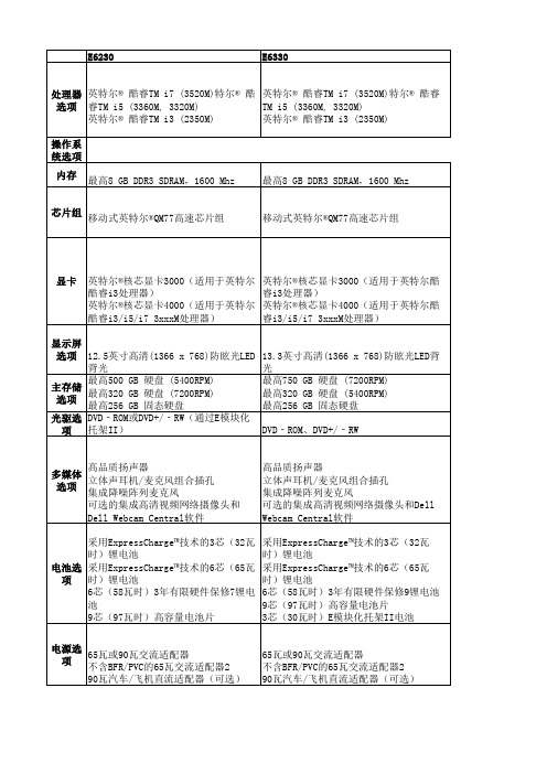
高品质扬声器 立体声耳机/麦克风组合插孔 集成降噪阵列麦克风 可选的集成高清视频网络摄像头和Dell Webcam Central软件 采用ExpressCharge™技术的3芯(32瓦时) 锂电池 采用ExpressCharge™技术的6芯(65瓦时) 锂电池 6芯(58瓦时)3年有限硬件保修7锂电池 9芯(97瓦时)高容量电池片 3芯(30瓦时)E模块化托架II电池
3英寸高清1366x768防眩光led背光最高750gb硬盘7200rpm最高320gb硬盘5400rpm最高256gb固态硬盘主存储选项光驱选项dvdromdvdrw多媒体选项高品质扬声器立体声耳机麦克风组合插孔集成降噪阵列麦克风可选的集成高清视频网络摄像头和dellwebcamcentral软件高品质扬声器立体声耳机麦克风组合插孔集成降噪阵列麦克风可选的集成高清视频网络摄像头和dellwebcamcentral软件电池选项采用expresscharge?技术的3芯32瓦时锂电池采用expresscharge?技术的6芯65瓦时锂电池6芯58瓦时3年有限硬件保修7锂电池9芯97瓦时高容量电池片采用expresscharge?技术的3芯32瓦时锂电池采用expresscharge?技术的6芯65瓦时锂电池6芯58瓦时3年有限硬件保修9锂电池9芯97瓦时高容量电池片3芯30瓦时e模块化托架ii电池电源选项65瓦或90瓦交流适配器不含bfrpvc的65瓦交流适配器290瓦汽车飞机直流适配器可选65瓦或90瓦交流适配器不含bfrpvc的65瓦交流适配器290瓦汽车飞机直流适配器可选连接选项101001000千兆位以太网无线lan选项
高品质扬声器 多媒体 立体声耳机/麦克风组合插孔 选项 集成降噪阵列麦克风 可选的集成高清视频网络摄像头和 Dell Webcam Central软件 采用ExpressCharge™技术的3芯(32瓦 时)锂电池 电池选 采用ExpressCharge™技术的6芯(65瓦 时)锂电池 项 6芯(58瓦时)3年有限硬件保修7锂电 池 9芯(97瓦时)高容量电池片 电源选 65瓦或90瓦交流适配器 项 不含BFR/PVC的65瓦交流适配器2 90瓦汽车/飞机直流适配器(可选)
国立科技USB数据传输适配器说明书

Manufacturer: National InstrumentsBoard Assembly Part Numbers (Refer to Procedure 1 for identification procedure): Part Number and Revision Description140050A-01L or later USB-8502(1 Port)140050A-02L or later USB-8502(2 Port with Sync)142889A-01L or later USB-8506(1 Port)142889A-02L or later USB-8506(2 Port with Sync)Volatile MemoryTarget Data Type Size Backup1Accessible Accessible ProcedureInstruction & data memory FPGAOn-chipMemory111KB/Port No No Yes Cycle Power Non-Volatile Memory (incl. Media Storage)Target Data Type Size BatteryBackupUserAccessibleSystemAccessibleSanitizationProcedureDevice configuration and info EEPROM 128 Kb No No Yes None 1 Refer to Terms and Definitions section for clarification of User and System AccessibleProceduresProcedure 1 – Board Assembly Part Number identification:To determine the Board Assembly Part Number and Revision, Open up the case of the USB module, look for a laser printed label on the top side of the PCB board, it should contain the part number and revision in the format of 14XXXXX-XXLTerms and DefinitionsCycle Power:The process of completely removing power from the device and its components and allowing for adequate discharge. This process includes a complete shutdown of the PC and/or chassis containing the device; a reboot is not sufficient for the completion of this process.Volatile Memory:Requires power to maintain the stored information. When power is removed from this memory, its contents are lost. This type of memory typically contains application specific data such as capture waveforms.Non-Volatile Memory:Power is not required to maintain the stored information. Device retains its contents when power is removed.This type of memory typically contains information necessary to boot, configure, or calibrate the product or may include device power up states.User Accessible:The component is read and/or write addressable such that a user can store arbitrary information to the component from the host using a publicly distributed NI tool, such as a Driver API, the System Configuration API, or MAX. System Accessible:The component is read and/or write addressable from the host without the need to physically alter the product. Clearing:Per NIST Special Publication 800-88 Revision 1, “clearing” is a logical technique to sanitize data in all User Accessible storage locations for protection against simple non-invasive data recovery techniques using the same interface available to the user; typically applied through the standard read and write commands to the storage device.Sanitization:Per NIST Special Publication 800-88 Revision 1, “sanitization” is a process to render access to “Target Data” on the media infeasible for a given level of effort. In this document, clearing is the degree of sanitization described.。
40301电源芯片管脚定义

40301电源芯片管脚定义(实用版)目录1.电源管理芯片概述2.电源管理芯片引脚定义及功能1.VCC 电源管理芯片供电2.VDD 门驱动器供电电压输入或初级控制信号供电源3.VID-4 CPU 与 CPU 供电管理芯片 V1D 信号连接引脚4.RUNSDSHDNEN 不同芯片的开始工作引脚5.PGOOD CPU 内核供电电路正常工作信号输出6.VTTGOOD CPU 外核供电正常信号输出正文一、电源管理芯片概述电源管理芯片,顾名思义,是用于管理电子设备电源的芯片。
它可以实现对电能的变换、分配和控制等功能,以保证电子设备正常工作。
电源管理芯片在众多电子产品中都有应用,如计算机、通信设备、嵌入式系统等。
二、电源管理芯片引脚定义及功能电源管理芯片具有多个引脚,每个引脚具有特定的功能。
下面详细介绍一下各个引脚的定义及功能:1.VCC:电源管理芯片供电引脚,为芯片本身提供电源。
2.VDD:门驱动器供电电压输入或初级控制信号供电源引脚。
此引脚为门驱动器提供工作电压,同时负责接收初级控制信号。
3.VID-4:CPU 与 CPU 供电管理芯片 V1D 信号连接引脚。
这个引脚主要指示芯片的输出信号,使两个场管输出正确的工作电压。
4.RUNSDSHDNEN:不同芯片的开始工作引脚。
这个引脚用于控制芯片的启动和工作状态。
5.PGOOD:CPU 内核供电电路正常工作信号输出引脚。
当此引脚输出信号为高电平时,表示 CPU 内核供电电路正常工作。
6.VTTGOOD:CPU 外核供电正常信号输出引脚。
当此引脚输出信号为高电平时,表示 CPU 外核供电正常。
通过以上介绍,可以了解到电源管理芯片引脚的定义和功能。
第1页共1页。
