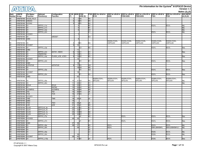
EP3C25 - 引脚信息
EDA开发板
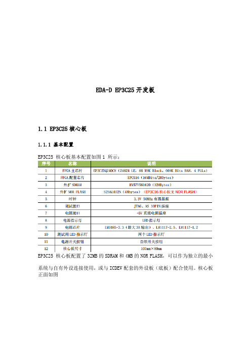
EDA-D EP3C25开发板1.1 EP3C25核心板1.1.1 基本配置EP3C25 核心板基本配置如图1 所示:EP3C25 核心板配置了32MB的SDRAM和4MB的NOR FLASH,可以作为独立的最小系统与自有外设连接使用,或与ICDEV配套的外设板(底板)配合使用。
核心板正面如图2 所示,背面如图3所示。
1.1.2 跳线说明1)BEEP 跳线:该跳线用于连接 ICDEV 外设板的蜂鸣器控制端,在连接外设板的情况下给EP3C25 下载SOF 文件或POF文件时会导致蜂鸣器长鸣,断开跳线可以避免蜂鸣器发声(尤其是下载POF 文件时耗时较长);如果不使用外设板,该跳线的作用仅仅是将该I/O连接到插针。
2)FLASH片选跳线:该跳线用于连接NOR FLASH 片选信号线,在不使用FLASH 的情况下,该跳线的引出针脚可以作为EP3C25的普通 I/O口使用。
3)MSEL1 跳线:该跳线用于连接或断开EP3C25的MSEL1管脚与2.5VA的连接,在通过配置芯片启动时需要用到该跳线。
1.2 外设板(底板)外设板基本配置如图4所示外设板正面如图5所示,背面如图6 所示2.1EDA-D EP3C25结构功能特点:EDA-D系列是深圳市启点时代科技有限公司针对电子竞赛、IP验证、FPGA教学和开发设计的一系列开发板,该系列开发板分为核心板和底板设计,核心板和底板可以分离,核心板可以独立运行,底板设计了大量实验资源,对于实验验证和开发测试都非常有用,配合丰富的实验例程和详细的实验指导,可以在尽可能短的时间内掌握基本的CPLD和FPGA设计方法和思路,所有配套实验均提供源代码和工程文件,用户可以直接使用该代码或者修改后用于自己的设计开发中。
所有底板的器件均分配了独立的IO,不存在IO复用,可以同时使用底板的全部资源!针对CPLD/FPGA入门较难的特点,实验代码在设计上由浅入深,从最基本的基础逻辑门开始,尽量避免一开始就罗列一堆代码,代码设计注重思路与基础,每个实验源码均有功能说明、管脚分配和验证说明,部分综合性实验例程有设计思路分析。
FPGA可编程逻辑器件芯片EP3C25E144C8N中文规格书
Stratix II Device Handbook, Volume 1
DC & Switching Characteristics Stratix II Device Handbook, Volume 1
DC & Switching Characteristics
Table 5–75. Stratix II I/O Output Delay for Column Pins (Part 5 of 8)
I/O Standard
Drive Strength
Parameter
Differential
8 mA
tO P
SSTL-2 Class I
tD I P
12 mA tO P
tD I P
Differential
16 mA tO P
SSTL-2 Class II
tD I P
20 mA tO P
tD I P
(1)
tD I P
4 mA
tO P
tD I P
6 mA
tO P
tD I P
8 mA
tO P
tD I P
10 mA tO P
tD I P
12 mA tO P
(1)
tD I P
16 mA tO P
tD I P
18 mA tO P
tD I P
20 mA tO P
(1)
tD I P
tO P
tD I P
tO P
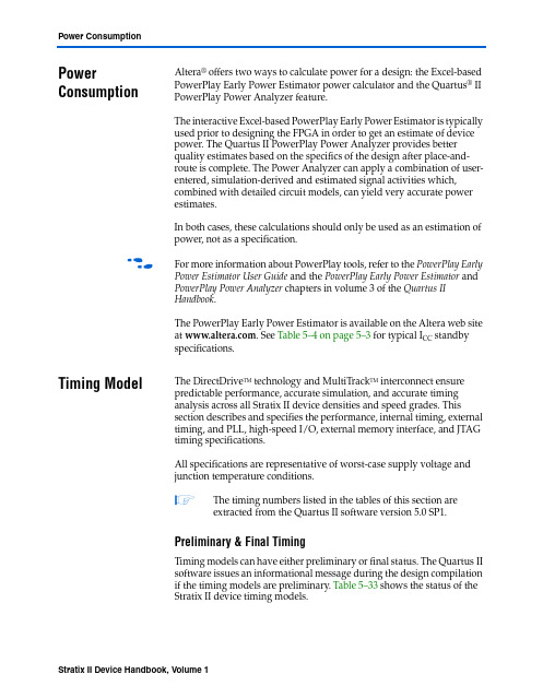
In both cases, these calculations should only be used as an estimation of power, not as a specification.
FPGA可编程逻辑器件芯片EP3C25E144I7N中文规格书
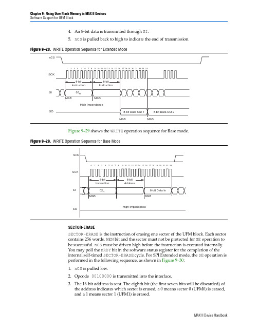
Software Support for UFM Block4.An 8-bit data is transmitted through SI .5.nCS is pulled back to high to indicate the end of transmission.Figure 9–29 shows the WRITE operation sequence for Base mode.SECTOR-ERASESECTOR-ERASE is the instruction of erasing one sector of the UFM block. Each sector contains 256 words. WEN bit and the sector must not be protected for SE operation to be successful. nCS must be driven high before the instruction is executed internally. You may poll the nRDY bit in the software status register for the completion of the internal self-timed SECTOR-ERASE cycle. For SPI Extended mode, the SE operation is performed in the following sequence, as shown in Figure 9–30:1.nCS is pulled low.2.Opcode 00100000 is transmitted into the interface.3.The 16-bit address is sent. The eighth bit (the first seven bits will be discarded) of the address indicates which sector is erased; a 0 means sector 0 (UFM0) is erased,and a 1 means sector 1 (UFM1) is erased.Figure 9–28.WRITE Operation Sequence for Extended ModenCSSCKSISOFigure 9–29.WRITE Operation Sequence for Base ModenCSSCKSISOCreating Memory Content FileMemory Initialization for the altufm_parallel MegafunctionFor the parallel interface, if a HEX file is used to initialize the memory content for the altufm megafunction, you have to fully specify all 16 bits in each memory address, regardless of the data width selected. If your data width is less than 16 bits wide, your data must be placed in the MSBs of the data word and the remaining LSBs must be padded with 1’s.For an example, if address _width = 3 and data _width = 8 are selected for the altufm_parallel megafunction, the HEX file should contain eight addresses of data (23 addresses), each word containing 16bits. If the initial content at the location 000 is intended to be 10101010, you should specify 1010101011111111 for address 000 in the HEX file.1This specification applies only to HEX files used with the parallel interface. MIFs do not require you to fully specify 16 bits for each data word. However, both MIF and HEX files require you to specify all addresses of data according to the address _width selected in the megafunction.Memory Initialization for the altufm_spi MegafunctionThe same 16-bit data padding mentioned for altufm_parallel is required for HEX files used with the SPI Base (8 bits) and Extended (16 bits) mode interface. In addition, for SPI Base and Extended mode, you must fully specify memory content for all512addresses (both sector 0 and sector 1) in the HEX file and MIF, even if sector 1 is not used. You can put valid data for SPI Base mode addresses 0to 255 (sector 0), and initialize sector 1 to all ones.Figure 9–48.Page 4 of the altufm MegafunctionChapter 9:Using User Flash Memory in MAX II DevicesCreating Memory Content FileMemory Initialization for the altufm_i2c MegafunctionThe MAX II UFM physical memory block contains a 16-bit wide and 512deep (9-bitaddress) array. The altufm_i2c megafunction uses the following smaller array sizes:■An 8-bit wide and 128 deep (7-bit address) mapping for 1 Kbit memory size■An 8-bit wide and 256 deep (8-bit address) mapping for 2 Kbits memory size■An 8-bit wide and 512 deep (9-bit address) mapping for 4 Kbits memory size■An 8-bit wide and 1,024 deep (10-bit address) mapping for 8 Kbits memory sizeAltera recommends that you pad the MIF or HEX file for both address and data widthto fill the physical memory map for the UFM block and ensure the MIF/HEX filerepresents a full 16-bit word size and a 9-bit address space.Memory Map for 1-Kbit Memory InitializationFigure9–49 shows the memory map initialization for the altufm_i2c megafunction of1-Kbit memory size. The altufm_i2c megafunction byte address location of 00h to3Fh is mapped to the UFM block address location of 000h to 03Fh. The altufm_i2cmegafunction byte address location of 40h to 7Fh is mapped to the UFM blockaddress location of 1C0h to 1FFh. Altera recommends that you pad the unusedaddress locations of the UFM block with all ones.Figure9–49.Memory Map for 1-Kbit Memory InitializationMIF or HEX File Contents – to representthe actual data and address size for the UFM blockMemory Map for 2-Kbit Memory InitializationFigure9–50 shows the memory map initialization for the altufm_i2c megafunction of2 Kbits of memory. The altufm_i2c megafunction byte address location of 00h to 7Fhis mapped to the UFM block address location of 000h to 07Fh. The altufm_i2cmegafunction byte address location of 80h to FFh is mapped to the UFM blockaddress location of 180h to 1FFh. Altera recommends that you pad the unusedaddress location of the UFM block with all ones.Chapter 12:Real-Time ISP and ISP Clamp for MAX II DevicesDocument Revision HistoryChapter 13:IEEE 1149.1 (JTAG) Boundary-Scan Testing for MAX II DevicesIEEE Std. 1149.1 BST Operation Control。
FPGA可编程逻辑器件芯片EP3C25F256I7N中文规格书
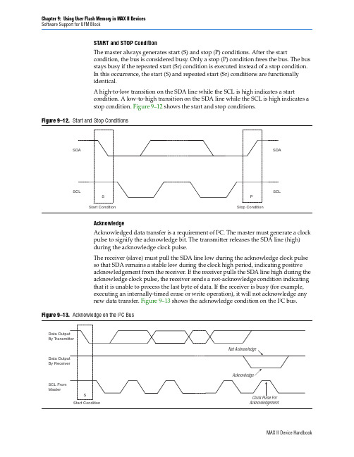
Chapter 9:Using User Flash Memory in MAX II Devices Software Support for UFM BlockSTART and STOP ConditionThe master always generates start (S) and stop (P) conditions. After the startcondition, the bus is considered busy. Only a stop (P) condition frees the bus. The bus stays busy if the repeated start (Sr) condition is executed instead of a stop condition. In this occurrence, the start (S) and repeated start (Sr) conditions are functionally identical.A high-to-low transition on the SDA line while the SCL is high indicates a startcondition. A low-to-high transition on the SDA line while the SCL is high indicates a stop condition. Figure 9–12 shows the start and stop conditions.AcknowledgeAcknowledged data transfer is a requirement of I 2C. The master must generate a clock pulse to signify the acknowledge bit. The transmitter releases the SDA line (high) during the acknowledge clock pulse.The receiver (slave) must pull the SDA line low during the acknowledge clock pulse so that SDA remains a stable low during the clock high period, indicating positive acknowledgement from the receiver. If the receiver pulls the SDA line high during the acknowledge clock pulse, the receiver sends a not-acknowledge condition indicating that it is unable to process the last byte of data. If the receiver is busy (for example, executing an internally-timed erase or write operation), it will not acknowledge any new data transfer. Figure 9–13 shows the acknowledge condition on the I 2C bus.Figure 9–12.Start and Stop ConditionsSDA SCLSDASCLSPStart ConditionStop ConditionFigure 9–13.Acknowledge on the I 2C BusBy T By Recei v SCL From MasterStart ConditionAcknowledgementChapter 10:Replacing Serial EEPROMs with MAX II User Flash Memory List of Vendors and DevicesTable10–10.Rohm Co., Ltd. Device Characteristics(Part 1 of 2)Section IV: In-System ProgrammabilityRevision HistoryChapter 11:In-System Programmability Guidelines for MAX II DevicesDocument Revision HistoryChapter 12:Real-Time ISP and ISP Clamp for MAX II Devices ISP ClampWith the ISP clamp feature in MAX II devices, you can hold each I/O pin of a device to a specified static state when programming the device. You can set the state in the Quartus II software. After successfully programming the device in ISP clamp mode, those I/O pins will be released and function according to the new design.This feature can be used to indicate when the device is being programmed and when the programming is done by setting a particular pin to a specific state (different from the state when the device is in user mode) when the device enters ISP clamp mode.How ISP Clamp WorksWhen the ISP clamp feature is used, you can set the I/O pins to tri-state (default), high, low, or even sample the existing state of a pin and hold the pin to that state when the device is in ISP clamp operation. The software determines the values to be scanned into the boundary-scan registers of each I/O pin, based on your settings. This will determine the state of the pins to be clamped to when the device programming is in progress. The weak I/O pull-up resistors are disabled during programming when the ISP clamp feature is used, even if the I/O is clamped to a tri-state value.Before clamping the I/O pins, the SAMPLE/PRELOAD JTAG instruction is firstexecuted to load the appropriate values to the boundary-scan registers. After loading the boundary-scan registers with the appropriate values, the EXTEST instruction is executed to clamp the I/O pins to the specific values loaded into the boundary-scan registers during SAMPLE/PRELOAD.If you choose to sample the existing state of a pin and hold the pin to that state when the device enters ISP clamp mode, you must make sure that the signal is in steady state. You need a steady state signal because you cannot control the sample set-up time as it depends on the TCK frequency as well as the download cable and software. You might not capture the correct value when sampling a signal that toggles or is not static for long periods of time. Figure 12–5 shows the ISP clamp operation.Using ISP Clamp in the Quartus II SoftwareYou have to define the states of the I/O pins to use the ISP clamp feature. There are two ways to define the pin states in the Quartus II software. You can either:■Use an I/O Pin State file (.ips ), or■Use the Assignment Editor to set the clamp states of the pinsFigure 12–5.ISP Clamp OperationI/Os Drive Out According to DesignBefore Programming (User Mode)1DataI/Os Clamped to Specified States During Programming (ISP Clamp Mode)2I/Os Drive OutAccording to New DesignAfter Programming (User Mode)3。
EP3C25Q240C8中文资料(Altera)中文数据手册「EasyDatasheet - 矽搜」

—
1.71 1.8 1.89
V
—
1.425 1.5 1.575 V
电源电压为输出缓冲器,1.2-V
手术
—
1.14 1.2 1.26
V
VCCA (3)
VCCD_PLL (3) VI VO
供应(模拟)电压PLL
调节器
供应(数字)电压PLL
输入电压 输出电压
TJ
工作结温
tRAMP IDiode
电源斜坡时间
电源电压为输出缓冲器,3.3-V
手术
—
1.15 1.2 1.25
V
—
3.135 3.3 3.465 V
电源电压为输出缓冲器,3.0-V
手术
—
2.85
3
3.15
V
VCCIO (3), (4)
电源电压为输出缓冲器,2.5-V
手术
电源电压为输出缓冲器,1.8-V
手术
电源电压为输出缓冲器,1.5-V
手术
—
2.375 2.5 2.625 V
直流电流幅度
当启用PCI-钳位二极管
—
— — —
对于商业用途 工业用 对于扩展温度 对于汽车使用 标准上电复位
(POR) (5) 快速POR (6)
—
2.375 2.5 2.625 V
1.15 1.2 1.25
V
–0.5 —
3.6
V
0
—
VCCIO
V
0
—
85
°C
–40 — 100 °C
–40 — 125 °C
表1-4 列出I / O引脚泄漏 目前Cyclone III器件.
f
有关功耗估算工具更多信息 ,请参
E-PLAY-3C25-Q使用说明说doc
PIN_133 PIN_132 PIN_131
D0
D1
D2
16 位数据总
PIN_139
A3
PIN_128
D3
线。FLASH、
PIN_137 PIN_126 PIN_120 PIN_119 PIN_118 PIN_117
A4
PIN_166
A5
21 位地址总 PIN_164
线。FLASH、
A6
SRAM、网络控 PIN_161
SRAM: IS61LV5128AL-10TLI
网络接口 音频接口
SDRAM:HY57V641620FTP-7
USB 控制器:CY7C68013A-56
网络控制器:DM9000AEP
电源模块:AMS1117 0589(1.2V),AS1117 2.5 9926(2.5V),LT1086 CM-3.3(3.3V)
京
PIN_80 PIN_81
nIOW nIOR
备注
片选信号 写 DM9000A 读 DM9000A
PIN_84 PIN_87
北SSD8
SSD9
PIN_82
INT
PIN_83
CMD
中断 命令
PIN_88
SSD10
FPGA 对 SDRAM 数据、地址及控制信号分配:
FPGA 管脚 网络或符号
备注
FPGA 管脚
PIN_216
SDRAM_D0
PIN_240
网络或符号 SDRAM_A4
备注
PIN_214
SDRAM_D1
PIN_239
SDRAM_A5
PIN_207
SDRAM_D2
PIN_238
EP3C25Q240C8N中文资料(Altera)中文数据手册「EasyDatasheet - 矽搜」

手术
—
1.15 1.2 1.25
V
—
3.135 3.3 3.465 V
电源电压为输出缓冲器,3.0-V
手术
—
2.85
3
3.15
V
VCCIO (3), (4)
电源电压为输出缓冲器,2.5-V
手术
电源电压为输出缓冲器,1.8-V
手术
电源电压为输出缓冲器,1.5-V
手术
—
2.375 2.5 2.625 V
(4)所有输入缓冲器由在V驱动
供电.
(5)50-200毫秒之间POR时间标准POR范围.每个单独电源应达到在推荐工作范围 50毫秒.
3-9毫秒(6)POR时间,快速POR范围.每个单独电源应在3毫秒达到推荐工作范围内.
芯片中文手册,看全文,戳
第 1章: Cyclone III器件数据表
表1-2 列出所允许最大输入电压过冲和 过冲电压作为在装置寿命百分比持续时间. 允许最大过冲持续时间被指定为高时间比设备寿命百分比.
Max
Unit
1.8
V
3.9
V
3.75
V
1.8
V
3.95
V
40
mA
±2000
V
±500
V
150
°C
125
°C
表1-2 and
芯片中文手册,看全文,戳
芯片中文手册,看全文,戳
July 2012 CIII52001-3.5
CIII52001-3.5
1.Cyclone III器件数据表
本章介绍电气特性,开关特性,以及I / O
对Cyclone时机
EP3C25核心板快速使用指南
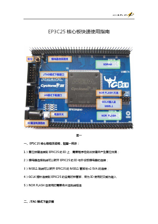
EP3C25核心板快速使用指南图一一、EP3C25核心板相关说明,如图一所示:1)复位按键连接到EP3C25的IO上,需要程序检测该按键并产生复位效果; 2)蜂鸣器选择跳线可以断开EP3C25的IO与外设板蜂鸣器的连接;3)MSEL1跳线可以断开EP3C25的MSEL1管脚与+2.5VA的连接;4)GCLK插针连接到EP3C25的全局时钟管脚,做为IO使用时只能为输入 5)NOR FLASH在使用时需要将片选跳线短连二、JTAG模式下载步骤1)下载线连接到JTAG模式下载接口;2)接上5V电源,打开电源开关(电源灯亮);3)打开QUARTUS II;4)File Open Project打开QUARTUS II工程文件(*.qpf);5)编译工程:Processing Start Compilation;6)编译成功后打开下载窗口:Tools Programmer;7)点击HardwareSetup按钮添加下载器;8)下载模式选择为JTAG(默认为JTAG下载模式);9)单击Auto Detect按钮查看是否能找到目标器件;10)找到目标器件后,双击<none>打开文件选择窗口选择正确的sof文件; 11)Program/Configure复选框选中;12)单击Start按钮下载,下载完毕后将可以看到程序运行的效果。
三、AS模式下载步骤1)接上述步骤,断电;2)将下载线从JTAG下载接口换到AS接口;3)将MSEL1跳线帽摘掉;4)通电;5)在下载界面中将下载模式改为Acting Serial Programming模式,即AS模式; 6)在弹出的对话框中选择“是”;7)点击Add File按钮添加正确的pof文件(需要与配置芯片相匹配);8)Program/Configure和Verify复选框选中;9)单击Start按钮开始下载,由于是将配置文件下载到串行Flash中,故速度较慢; 10)下载完毕之后断电,拔掉下载线,将MSETL1跳线帽接上;11)重新上电,程序运行并查看运行效果。
FPGA可编程逻辑器件芯片EP3C25F256C6中文规格书

Min Max Min Max Min Max Min Max Min Max Min Max Unit — 1,225 — 1,592 — 1,960 — 1,858 — 2,171 — 2,214 ps
— 89 — 115 — 142 — 569 — 609 — 616 ps
Maximum Input and Output Clock Rates
Chapter 5: DC and Switching Characteristics Timing Model and Specifications
Table 5–31. MAX II IOE Programmable Delays
MAX II / MAX IIG
MAX IIZ
–3 Speed Grade
MAX II Device Handbook
Section III. User Flash Memory
MAX II Device Handbook
Section III: User Flash Memory Revision History
MAX II Device Handbook
188
188
188
188
188
188 MHz
200
200
200
200
200
200 MHz
200
200
200
200
200
200 MHz
150
150
150
150
150
150 MHz
304
304
304
304
304
304 MHz
MAX II Device Handbook
TL2543

图3.5TLC2543芯片引脚图图3.6内部结构图3.6 TLC2543芯片引脚及内部结构TLC2543是德州仪器公司生产的12位开关电容型逐次逼近模数转换器,最大转换时间10us,11个模拟输入通道,3路内置自测试方式,采样率为66KSPS,线性误差±1LSBmax,有转换结束输出EOC,具有单极、双极性输出,可编程的MSB或LSB前导,可编程输出数据长度。
它具有三个控制输入端,采用简单三线SPI串行接口可方便的与微机进行连接,图3.5和图3.6分别是TLC2543的引脚排列图和内部结构图。
表3.2是TLC2543的引脚功能说明。
3.7 TLC2543的工作方式和输入通道的选择TLC2543是一个多通道和多工作方式的模数转换器件。
图3.5为其芯片引脚图,图3.6是它的内部结构图。
其工作方式和输入通道的选择是通过向TLC2543的控制寄存器写入一个八位的控制字来实现的。
这个八位控制字由四个部分组成:D7D6D5D4选择输入通道,D3D2选择输出数据长度,D1选择输出数据顺序,D0选择转换结果的极性。
八位控制字的各位的含义如表3.3所示。
主机以MSB为前导方式将控制字写入TLC2543的控制寄存器,每个数据位都是在CLOCK序列的上升沿被写入控制器。
表3.2引脚功能说明3.7.1 TLC2543的读写时序当片选信号/CS为高电平时,CLOCK和DATA-IN被禁止、DATA-OUT为高阻状态,以便SPI总线上的其它器件让出总线。
在片选信号/CS的下降沿,A/D转换结果的第一位数据出现在DATA-OUT引脚上,A/D转换结果的其他数据位在时钟信号CLOCK的下降沿被串行输出到DATA-OUT。
在片选信号/CS下降以后,时钟信号CLOCK的前八个上升沿将八位控制字从DATA_IN引脚串行输入到TLC2543的控制寄存器。
在片选信号/CS下降以后,经历8个(12个或16个)时钟信号完成对A/D转换器的一次读写。
EP3C25_管脚列表
DQS1L/CQ1L#, DPCLK1
DQ3L
DQ1L
32 33 34
DQ3L
DQ1L
Sep.
DIFFIO_L15p DIFFIO_L15n 35 36 37 DIFFIO_B1p 38 DIFFIO_B1n DIFFIO_B2p DIFFIO_B2n DIFFIO_B3p 39
Res.
40 41 42 3 44
DQ1L
DQ1L
DQ1L
DQ1L
Adj. Adj. Adj. Adj.
DQ1L DQ1L DQS0L/CQ1L, DPCLK0
DQ1L DQ1L DQS0L/CQ1L, DPCLK0
Sep. Sep.
DIFFIO_L6p DIFFIO_L6n DCLK DATA0 nCONFIG TDI TCK TMS TDO nCE DIFFCLK_0p DIFFCLK_0n DIFFCLK_1p DIFFCLK_1n DIFFIO_L7p DIFFIO_L7n DIFFIO_L8p DIFFIO_L8n DIFFIO_L9p DIFFIO_L9n
DQ1L DQ1L DQ1L DQ1L
DQ1L DQ1L DQ1L DM1L/BWS#1L DQ3L DQ3L
DQ1L DQ1L DQ1L DM1L0/BWS#1L1 DQ1L DQ1L DQ1L
Sep. Sep. Adj. Adj. Adj. Adj. Sep.
29 DIFFIO_L10p
39 40 41 K2
PLL1_CLKOUTp PLL1_CLKOUTn DIFFIO_B4p DIFFIO_B4n
P6 U2 V2 N7 N8
DQS1B/CQ1B#, CDPCLK2
DQS1B/CQ1B#, CDPCLK2
FPGA可编程逻辑器件芯片EP3C25F324C8中文规格书

Chapter 5:DSP Blocks in Stratix III DevicesDSP Block Resource DescriptionsShift registers are useful in DSP functions such as FIR filters. When implementing 18×18 or smaller width multipliers, you do not need external logic to create the shift register chain because the input shift registers are internal to the DSP block. This implementation significantly reduces the logical element (LE) resources required, avoids routing congestion, and results in predictable timing.The first multiplier in every half DSP block (top- and bottom-half) in Stratix IIIdevices has a multiplexer for the first multiplier B-input (lower-leg input) register to select between general routing and loopback, as shown in Figure 5–6. In loopback mode, the most significant 18-bit registered outputs are connected as feedback to the multiplier input of the first top multiplier in each half DSP block. Loopback modes are used by recursive filters where the previous output is needed to compute the current output.The loopback mode is described in detail in “Two-Multiplier Adder Sum Mode” on page 5–21.Table 5–3 lists the input register modes for the DSP block.Multiplier and First-Stage AdderThe multiplier stage natively supports 9×9, 12×12, 18×18, or 36×36 multipliers. Other wordlengths are padded up to the nearest appropriate native wordlength; for example, 16×16 would be padded up to use 18×18. Refer to “IndependentMultiplier Modes” on page 5–15 for more details. Depending on the data width of the multiplier, a single DSP block can perform many multiplications in parallel.Each multiplier operand can be a unique signed or unsigned number. Two dynamic signals, signa and signb , control the representation of each operand, respectively . A logic 1 value on the signa/signb signal indicates that data A/data B is a signed number; a logic 0 value indicates an unsigned number. Table 5–4 lists the sign of the multiplication result for the various operand sign representations. The result of the multiplication is signed if any one of the operands is a signed value.Table 5–3.Input Register ModesNotes to Table 5–3:(1)The multiplier operand input wordlengths are statically configured at compile time.(2)Available only on the A-operand.(3)Only one loopback input is allowed per Half-Block. See Figure 5–15for details.Table 5–4.Multiplier Sign RepresentationChapter 5:DSP Blocks in Stratix III Devices Operational Mode DescriptionsFour-Multiplier AdderIn the four-multiplier adder configuration shown in Figure 5–17, the DSP block can implement two four-multiplier adders (one four-multiplier adder per half DSP block). These modes are useful for implementing one-dimensional and two-dimensional filtering applications. The four-multiplier adder is performed in two addition stages. The outputs of two of the four multipliers are initially summed in the two first-stage adder blocks. The results of these two adder blocks are then summed in thesecond-stage adder block to produce the final four-multiplier adder result, as shown by Equation 5–2 and Equation 5–3.The four-multiplier adder mode supports the round and saturation logic unit. You can use the pipeline registers and output registers within the DSP block to pipeline the multiplier-adder result, increasing the performance of the DSP block.Figure 5–17.Four-Multiplier Adder Mode for Half-DSP Blockdataa_0[ ]data b _0[ ]dataa_1[ ]data b _1[ ]dataa_2[ ]data b _2[ ]dataa_3[ ]data b _3[ ]result[ ]Chapter 6:Clock Networks and PLLs in Stratix III DevicesPLLs in Stratix III DevicesTable6–12.PLL Input Signals (Part 2 of 2)Table6–13 lists the PLL output signals for Stratix III devices. Table6–13.PLL Output Signals (Part 1 of 2)Chapter 6:Clock Networks and PLLs in Stratix III DevicesChapter Revision HistoryII–2Section II: I/O InterfacesRevision History。
Cyclone_III_EP3C25E144_外型尺寸-封装尺寸

June 2011
Altera Corporation
04R-00221-1.0
2
Altera Device Pacage Information
Package Outline
TOP VIEW
D D1
Pin 144
BOTTOM VIEW
D2
Pin 144
Pin 1
Pin 1 ID
Pin 1
E1
E2
Package Outline Dimension Table
Millimeters Symbol Min. A A1 A2 D D1 D2 E E1 E2 L L1 S b c e 0 0.20 0.17 0.09 6.55 0.45 6.55 1.45 0.05 1.30 Nom. 1.55 0.10 1.45 22.00 BSC 20.00 BSC 6.70 22.00 BSC 20.00 BSC 6.70 0.60 1.00 REF 0.22 0.50 BSC 3.5 7 0.27 0.20 6.85 0.75 6.85 Max. 1.65 0.15 1.60
Altera Corporation
04R-00221-1.0
E
Pin 36
Pin 36
A2 A1
A
See Detail A
Detail A
e
C Gage Plane
b
S L L1
0.25mm
04R-00221-1.0
June 2011
Altera Corporation
Altera Device Package Information
3
Document Revision History
EP3C16Q240引脚功能全-中文版

EP3C16Q240的引脚中文版供电和参考引脚VCCINT:类型:Power功能:内核电压1.2V/5%。
负责给内部逻辑阵列电源引脚供电。
引脚:共12个引脚,包括:10、40、53、61、74、115、129、140、163、190、204、228。
VCCIO[1..8]:类型:Power功能:I/O供电电压,共8个块,每个块供电电压可不一样,支持所有I/O输入输出标准。
驱动JTAG口(TMS、TCK、TDI和TDO)和以下引脚:nCONFIG, DCLK, DATA[15..0], nCE, nCEO, nWE, nRESET, nOE, FLASH_nCE, nCSO and CLKUSR。
引脚:共16个引脚,包括:7、15(Bank1);35、47(Bank2);66、77(Bank3);96、104(Bank4);124、136(Bank5);154、170(Bank6);192、206(Bank7);213、225(Bank8)。
GND:类型:Ground功能:器件所有的GND引脚应连接到板子地上。
引脚:共27个引脚,包括:11、16、36、42、48、54、62、67、75、79、97、105、116、125、130、138、141、156、165、172、191、193、205、208、215、227、229。
GNDA:类型:Ground功能:PLL的地。
需要和GND相连接。
引脚:共包括4个引脚,59(GNDA1)179(GNDA2)2(GNDA3)122(GNDA4)。
VREFB[1..8]N[0..2]:类型:I/O功能:参考电压引脚供电。
给每个块输入参考电压,如果某个块使用参考电压作为I/O口标准,这个块对应的参考电压引脚需要接到电源上。
如果不用,则直接接地。
引脚:共16个引脚,包括:13、39、76、114、139、169、184、223(VREFB1N0~ VREFB8N0);22、46、63、107、133、161、195、235(VREFB1N1~ VREFB8N1)。
FPGA-3C25开发板的研制 毕业论文
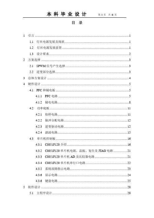
目录1 引言 (1)1.1 灯丝电源发展及现状 (1)1.2 灯丝电源发展前景 (1)1.3 设计要求 (2)2 方案选择 (3)2.1 SPWM信号产生选择 (3)2.2 逆变部分选择 (3)3 总体方案设计 (4)4 硬件设计 (5)4.1 PFC和辅电板 (5)4.1.1 PFC电路 (5)4.1.2 辅电电路 (8)4.2 功率底板 (11)4.2.1 取样电路 (11)4.2.2 脉冲分配电路 (12)4.2.3 逆变驱动电路 (12)4.2.4 滤波电路 (15)4.3 单片机控制板 (16)4.3.1 C8051F120介绍 (16)4.3.2 C8051F120单片机电源、晶振、复位及JTAG电路 (21)4.3.3 C8051F120单片机AD及比较器电路 (21)4.3.4 C8051F120单片机串行口电路 (22)4.3.5 系统故障指示电路 (23)4.3.6 显示电路 (24)4.3.6 键盘电路 (25)5 软件设计 (28)5.1 主程序设计 (28)5.2 显示程序设计 (30)5.3 键盘扫描程序设计 (32)5.4 AD采样程序设计 (34)5.5 串行口发送程序设计 (35)5.6 PWM程序设计 (37)6 系统调试 (38)6.1 硬件调试 (38)6.2 软件调试 (38)结论 (40)致谢 (41)参考文献 (42)1 引言1.1 灯丝电源发展及现状随着电子工业的飞速发展,电源作为供电装置正经历着日新月异的变化。
在工业生产,科学研究,甚至日常生活中都要用到各种各样的电源。
电源的种类随着电子元器件的更新换代而增加,目前已经发展出多种电源类型。
灯丝电源作为电源的一种,采用先进的开关电源电路和自适应技术,能自动判断大功率电子管内阻的大小来平滑电压并使大功率电子管工作在高精度状态,解决了大功率电子管灯丝因冷态电阻小易受电流冲击而产生的各类故障,延长电子管使用寿命。
EP3C25-引脚信息
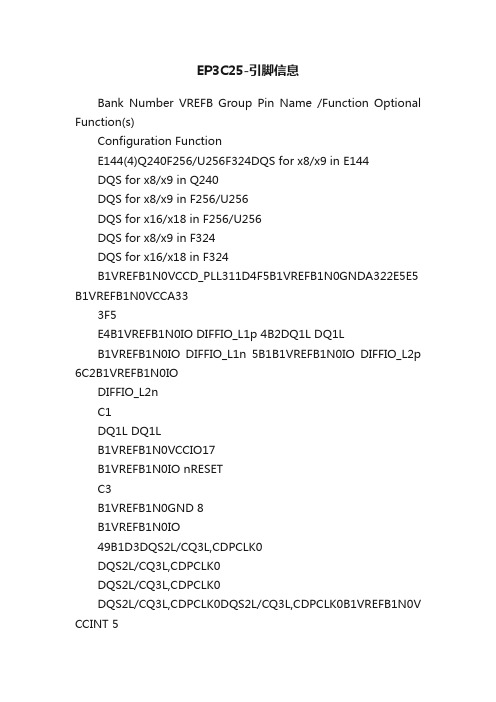
EP3C25-引脚信息Bank Number VREFB Group Pin Name /Function Optional Function(s)Configuration FunctionE144(4)Q240F256/U256F324DQS for x8/x9 in E144DQS for x8/x9 in Q240DQS for x8/x9 in F256/U256DQS for x16/x18 in F256/U256DQS for x8/x9 in F324DQS for x16/x18 in F324B1VREFB1N0VCCD_PLL311D4F5B1VREFB1N0GNDA322E5E5 B1VREFB1N0VCCA333F5E4B1VREFB1N0IO DIFFIO_L1p 4B2DQ1L DQ1LB1VREFB1N0IO DIFFIO_L1n 5B1B1VREFB1N0IO DIFFIO_L2p 6C2B1VREFB1N0IODIFFIO_L2nC1DQ1L DQ1LB1VREFB1N0VCCIO17B1VREFB1N0IO nRESETC3B1VREFB1N0GND 8B1VREFB1N0IO49B1D3DQS2L/CQ3L,CDPCLK0DQS2L/CQ3L,CDPCLK0DQS2L/CQ3L,CDPCLK0DQS2L/CQ3L,CDPCLK0DQS2L/CQ3L,CDPCLK0B1VREFB1N0V CCINT 510B1VREFB1N0IO DIFFIO_L3p C2D2DQ1LDQ1LB1VREFB1N0GND 11B1VREFB1N0IO DIFFIO_L3n DATA1, ASDO 612C1D1B1VREFB1N0IO VREFB1N0713F3F3B1VREFB1N0IODIFFIO_L4p FLASH_nCE, nCSO814D2E2B1VREFB1N0VCCIO115B1VREFB1N0IO DIFFIO_L4n D1E1DQ1LDQ1LB1VREFB1N0GND16B1VREFB1N0nSTATUS nSTATUS917F4G5B1VREFB1N0IO 18G5H6B1VREFB1N0IODIFFIO_L5pF2G2DQ1L DQ1LB1VREFB1N0VCCINT 19B1VREFB1N0IO DIFFIO_L5nF1G1DQ1LDQ1LB1VREFB1N0GND 20B1VREFB1N0IO DIFFIO_L6p 1021G2H2DQS0L/CQ1L,DPCLK0 DQS0L/CQ1L,DPCLK0DQS0L/CQ1L,DPCLK0DQS0L/CQ1L,DPCLK0DQS0L/CQ1L,DPCLK0DQS0L/CQ1L,DPCLK0B1VREFB1N0IO DIFFIO_L6n1122G1H1B1VREFB1N0DCLK DCLK 1223H1H4B1VREFB1N0IODATA01324H2H3B1VREFB1N0nCONFIG nCONFIG 1425H5H5B1VREFB1N0TDI TDI 1526H4J6B1VREFB1N0TCK TCK 1627H3J1B1VREFB1N0VCCIO117B1VREFB1N0TMS TMS 1828J5J2B1VREFB1N0GND 19B1VREFB1N0TDO TDO 2029J4J5B1VREFB1N0nCE nCE2130J3K6B1VREFB1N0CLK0DIFFCLK_0p2231E2F2B1VREFB1N0CLK1DIFFCLK_0n2332E1F1B2VREFB2N0CLK2DIFFCLK_1p2433M2N2B2VREFB2N0CLK3DIFFCLK_1n2534M1N1B2VREFB2N0IODIFFIO_L7p J2K2DQ1L DQ1L DQ1LB2VREFB2N0VCCIO22635B2VREFB2N0IO DIFFIO_L7n J1K1DQ1LDQ1LDQ1LB2VREFB2N0GND 2736B2VREFB2N0IO DIFFIO_L8p 2837K5DQ1L DQ1LDQ1LB2VREFB2N0IO DIFFIO_L8n 38L5DQ1LDM1L/BWS#1L DM1L0/BWS#1L1B2VREFB2N0IO L6B2VREFB2N0IO DIFFIO_L9p L2DQ3L DQ1L B2VREFB2N0IODIFFIO_L9n39L1DQ3LDQ1LVersion 1.4Notes (2), (3)Bank Number VREFBGroupPin Name /FunctionOptionalFunction(s)ConfigurationFunctionE144(4)Q240F256/U256F324DQS for x8/x9 inE144DQS for x8/x9 in Q240DQS for x8/x9 inF256/U256DQS for x16/x18 inF256/U256DQS for x8/x9 inF324DQS for x16/x18 inF324Version 1.4Notes (2), (3)Bank Number VREFBGroupPin Name /FunctionOptionalFunction(s)ConfigurationFunctionE144(4)Q240F256/U256F324DQS for x8/x9 inE144DQS for x8/x9 in Q240DQS for x8/x9 in F256/U256DQS for x16/x18 inF256/U256DQS for x8/x9 inF324DQS for x16/x18 inF324Version 1.4Notes (2), (3)Bank Number VREFBGroupPin Name /FunctionOptionalFunction(s)ConfigurationFunctionE144(4)Q240F256/U256F324DQS for x8/x9 inE144DQS for x8/x9 in Q240DQS for x8/x9 in F256/U256DQS for x16/x18 inF256/U256DQS for x8/x9 inF324DQS for x16/x18 inF324Version 1.4Notes (2), (3)Bank Number VREFBGroupPin Name /FunctionOptionalFunction(s)ConfigurationFunctionE144(4)Q240F256/U256F324DQS for x8/x9 inE144DQS for x8/x9 in Q240DQS for x8/x9 in F256/U256DQS for x16/x18 inF256/U256DQS for x8/x9 inF324DQS for x16/x18 inF324Version 1.4Notes (2), (3)Bank Number VREFBGroupPin Name /FunctionOptionalFunction(s)ConfigurationFunctionE144(4)Q240F256/U256F324DQS for x8/x9 inE144DQS for x8/x9 in Q240DQS for x8/x9 in F256/U256DQS for x16/x18 inF256/U256DQS for x8/x9 inF324DQS for x16/x18 inF324Version 1.4Notes (2), (3)Bank Number VREFBGroupPin Name /FunctionOptionalFunction(s)ConfigurationFunctionE144(4)Q240F256/U256F324DQS for x8/x9 inE144DQS for x8/x9 in Q240DQS for x8/x9 in F256/U256DQS for x16/x18 inF256/U256DQS for x8/x9 inF324DQS for x16/x18 inF324Version 1.4Notes (2), (3)Bank Number VREFBGroupPin Name /FunctionOptionalFunction(s)ConfigurationFunctionE144(4)Q240F256/U256F324DQS for x8/x9 inE144DQS for x8/x9 in Q240DQS for x8/x9 in F256/U256DQS for x16/x18 inF256/U256DQS for x8/x9 inF324DQS for x16/x18 inF324Version 1.4Notes (2), (3)Bank Number VREFBGroupPin Name /FunctionOptionalFunction(s)ConfigurationFunctionE144(4)Q240F256/U256F324DQS for x8/x9 inE144DQS for x8/x9 in Q240DQS for x8/x9 in F256/U256DQS for x16/x18 inF256/U256DQS for x8/x9 inF324DQS for x16/x18 inF324Version 1.4Notes (2), (3)Bank Number VREFBGroupPin Name /FunctionOptionalFunction(s)ConfigurationFunctionE144(4)Q240F256/U256F324DQS for x8/x9 inE144DQS for x8/x9 in Q240DQS for x8/x9 in F256/U256DQS for x16/x18 inF256/U256DQS for x8/x9 inF324DQS for x16/x18 inF324Version 1.4Notes (2), (3)Bank Number VREFBGroupPin Name /FunctionOptionalFunction(s)ConfigurationFunctionE144(4)Q240F256/U256F324DQS for x8/x9 inE144DQS for x8/x9 in Q240DQS for x8/x9 in F256/U256DQS for x16/x18 inF256/U256DQS for x8/x9 inF324DQS for x16/x18 inF324Version 1.4Notes (2), (3)Bank Number VREFBGroupPin Name /FunctionOptionalFunction(s)ConfigurationFunctionE144(4)Q240F256/U256F324DQS for x8/x9 inE144DQS for x8/x9 in Q240DQS for x8/x9 in F256/U256DQS for x16/x18 inF256/U256DQS for x8/x9 inF324DQS for x16/x18 inF324Version 1.4Notes (2), (3)Bank Number VREFBGroupPin Name /FunctionOptionalFunction(s)ConfigurationFunctionE144(4)Q240F256/U256F324DQS for x8/x9 inE144DQS for x8/x9 in Q240DQS for x8/x9 in F256/U256DQS for x16/x18 inF256/U256DQS for x8/x9 inF324DQS for x16/x18 inF324Version 1.4Notes (2), (3)Bank NumberVREFB GroupPin Name /Function Optional Function(s)Configuration FunctionE144(4)Q240F256/U256F324DQS for x8/x9 in E144DQS for x8/x9 in Q240DQS for x8/x9 in F256/U256DQS for x16/x18 in F256/U256DQS for x8/x9 in F324DQS for x16/x18 in F324Version 1.4Notes (2), (3)This exposed pad is used for electrical connectivity, and not for thermal purposes.(4) The E144 package has an exposed pad at the bottom of the package. This exposed pad is a ground pad that must be connected to the ground plane on your PCB. (1) E144, Q240, and F256 in the EP3C25 device do not have the MSEL [3] pin and do not support the Active Parallel (AP) configuration mode.(2) If the p pin or n pin is not available for the package, the particular differential pair is not supported.(3) For DQS pins that do not have the associated DQ pins, the particular DQS is not supported.。
FPGA可编程逻辑器件芯片EP3C25F324I7N中文规格书

Table 5–40. M512 Block Internal Timing Microparameters (Part 2 of 2) Note (1)
Байду номын сангаас
Symbol
tM 5 1 2 D ATA C O 1
tM 5 1 2 D ATA C O 2 tM 5 1 2 C L K L tM 5 1 2 C L K H tM 5 1 2 C L R
number is the minimum timing parameter for commercial devices.
Table 5–41. M4K Block Internal Timing Microparameters (Part 1 of 2) Note (1)
Symbol
tM 4 K R C tM 4 K W E R E S U tM 4 K W E R E H tM 4 K B E S U tM 4 K B E H
DC & Switching Characteristics
Figure 5–1. Receiver Input Waveforms for Differential I/O Standards
Single-Ended Waveform
VID VCM
Positive Channel (p) = VIH Negative Channel (n) = VIL Ground
Custom-Built Circuitry
Dedicated circuitry is built in the Stratix II devices to perform error detection automatically. This error detection circuitry in Stratix II devices constantly checks for errors in the configuration SRAM cells while the device is in user mode. You can monitor one external pin for the error and use it to trigger a re-configuration cycle. You can select the desired time between checks by adjusting a built-in clock divider.
基于GPS的恒温晶振频率校准系统的设计与实现

基于GPS的恒温晶振频率校准系统的设计与实现张帆;陈锟;朱正平;蓝加平【摘要】Aiming at high-precise frequency source magnitude necessary at present, a frequency calibration system for OCXO is designed by FPGA. A DPLL is designed to regulate the frequency of OCXO. The main idea behind is to use the 1PPS signal, which comes from GPS receiver, as a reference to calibrate the OCXO (oven controlled crystal oscillator) by integrating the long-term stability, excellent tracking and holding characteristic of GPS and the short-term accuracy of OCXO. The design principle and method are described in detail .The test results indicates that the system can fast achieve high precise and stability, frequency error is lower than 0.01 Hz. It can be used for standard of time and frequency measurement reference.%针对目前广泛对高精度频率源的需求,利用FPGA设计一种恒温晶振频率校准系统.系统以GPS接收机提供的秒脉冲信号为基准源,通过结合高精度恒温晶振短期稳定度高与GPS长期稳定特性好、跟踪保持特性强的优点,设计数字锁相环调控恒温晶振的频率.详细阐述系统的设计原理及方法,测试结果表明,恒温晶振的频率可快速被校准到10 MHz,频率偏差小于0.01 Hz,具有良好的长期稳定性,适合在多领域中作为时间频率的标准.【期刊名称】《电子设计工程》【年(卷),期】2013(021)008【总页数】4页(P91-94)【关键词】频率校准;恒温晶振;数字锁相环;FPGA【作者】张帆;陈锟;朱正平;蓝加平【作者单位】中南民族大学电子信息工程学院,湖北武汉430074【正文语种】中文【中图分类】TN752.2时钟技术在现代科学技术中有着广泛的应用,许多领域对时间指标的要求越来越高,如电力、通讯、军事、航空航天等,都需要高精度的同步时钟作为参考,协调整个系统的正常运行[1]。
- 1、下载文档前请自行甄别文档内容的完整性,平台不提供额外的编辑、内容补充、找答案等附加服务。
- 2、"仅部分预览"的文档,不可在线预览部分如存在完整性等问题,可反馈申请退款(可完整预览的文档不适用该条件!)。
- 3、如文档侵犯您的权益,请联系客服反馈,我们会尽快为您处理(人工客服工作时间:9:00-18:30)。
Bank Number VREFB Group Pin Name /Function Optional Function(s)Configuration FunctionE144(4)Q240F256/U256F324DQS for x8/x9 in E144DQS for x8/x9 in Q240DQS for x8/x9 in F256/U256DQS for x16/x18 in F256/U256DQS for x8/x9 in F324DQS for x16/x18 in F324B1VREFB1N0VCCD_PLL311D4F5B1VREFB1N0GNDA322E5E5B1VREFB1N0VCCA333F5E4B1VREFB1N0IO DIFFIO_L1p 4B2DQ1L DQ1LB1VREFB1N0IO DIFFIO_L1n 5B1B1VREFB1N0IO DIFFIO_L2p 6C2B1VREFB1N0IODIFFIO_L2nC1DQ1L DQ1LB1VREFB1N0VCCIO17B1VREFB1N0IO nRESETC3B1VREFB1N0GND 8B1VREFB1N0IO49B1D3DQS2L/CQ3L,CDPCLK0DQS2L/CQ3L,CDPCLK0DQS2L/CQ3L,CDPCLK0DQS2L/CQ3L,CDPCLK0DQS2L/CQ3L,CDPCLK0B1VREFB1N0VCCINT 510B1VREFB1N0IO DIFFIO_L3p C2D2DQ1LDQ1LB1VREFB1N0GND 11B1VREFB1N0IO DIFFIO_L3n DATA1, ASDO 612C1D1B1VREFB1N0IO VREFB1N0713F3F3B1VREFB1N0IODIFFIO_L4p FLASH_nCE, nCSO814D2E2B1VREFB1N0VCCIO115B1VREFB1N0IO DIFFIO_L4nD1E1DQ1LDQ1LB1VREFB1N0GND16B1VREFB1N0nSTATUS nSTATUS917F4G5B1VREFB1N0IO 18G5H6B1VREFB1N0IODIFFIO_L5pF2G2DQ1L DQ1LB1VREFB1N0VCCINT 19B1VREFB1N0IO DIFFIO_L5nF1G1DQ1LDQ1LB1VREFB1N0GND 20B1VREFB1N0IO DIFFIO_L6p 1021G2H2DQS0L/CQ1L,DPCLK0DQS0L/CQ1L,DPCLK0DQS0L/CQ1L,DPCLK0DQS0L/CQ1L,DPCLK0DQS0L/CQ1L,DPCLK0DQS0L/CQ1L,DPCLK0B1VREFB1N0IO DIFFIO_L6n1122G1H1B1VREFB1N0DCLK DCLK 1223H1H4B1VREFB1N0IODATA01324H2H3B1VREFB1N0nCONFIG nCONFIG 1425H5H5B1VREFB1N0TDI TDI 1526H4J6B1VREFB1N0TCK TCK 1627H3J1B1VREFB1N0VCCIO117B1VREFB1N0TMS TMS 1828J5J2B1VREFB1N0GND 19B1VREFB1N0TDO TDO 2029J4J5B1VREFB1N0nCE nCE2130J3K6B1VREFB1N0CLK0DIFFCLK_0p 2231E2F2B1VREFB1N0CLK1DIFFCLK_0n 2332E1F1B2VREFB2N0CLK2DIFFCLK_1p 2433M2N2B2VREFB2N0CLK3DIFFCLK_1n 2534M1N1B2VREFB2N0IODIFFIO_L7p J2K2DQ1L DQ1L DQ1LB2VREFB2N0VCCIO22635B2VREFB2N0IO DIFFIO_L7n J1K1DQ1LDQ1LDQ1LB2VREFB2N0GND 2736B2VREFB2N0IO DIFFIO_L8p 2837K5DQ1L DQ1LDQ1LB2VREFB2N0IO DIFFIO_L8n 38L5DQ1LDM1L/BWS#1L DM1L0/BWS#1L1B2VREFB2N0IO L6B2VREFB2N0IO DIFFIO_L9p L2DQ3L DQ1L B2VREFB2N0IODIFFIO_L9n39L1DQ3LDQ1LVersion 1.4Notes (2), (3)Bank Number VREFBGroupPin Name /FunctionOptionalFunction(s)ConfigurationFunctionE144(4)Q240F256/U256F324DQS for x8/x9 inE144DQS for x8/x9 in Q240DQS for x8/x9 inF256/U256DQS for x16/x18 inF256/U256DQS for x8/x9 inF324DQS for x16/x18 inF324Version 1.4Notes (2), (3)Bank Number VREFBGroupPin Name /FunctionOptionalFunction(s)ConfigurationFunctionE144(4)Q240F256/U256F324DQS for x8/x9 inE144DQS for x8/x9 in Q240DQS for x8/x9 inF256/U256DQS for x16/x18 inF256/U256DQS for x8/x9 inF324DQS for x16/x18 inF324Version 1.4Notes (2), (3)Bank Number VREFBGroupPin Name /FunctionOptionalFunction(s)ConfigurationFunctionE144(4)Q240F256/U256F324DQS for x8/x9 inE144DQS for x8/x9 in Q240DQS for x8/x9 inF256/U256DQS for x16/x18 inF256/U256DQS for x8/x9 inF324DQS for x16/x18 inF324Version 1.4Notes (2), (3)Bank Number VREFBGroupPin Name /FunctionOptionalFunction(s)ConfigurationFunctionE144(4)Q240F256/U256F324DQS for x8/x9 inE144DQS for x8/x9 in Q240DQS for x8/x9 inF256/U256DQS for x16/x18 inF256/U256DQS for x8/x9 inF324DQS for x16/x18 inF324Version 1.4Notes (2), (3)Bank Number VREFBGroupPin Name /FunctionOptionalFunction(s)ConfigurationFunctionE144(4)Q240F256/U256F324DQS for x8/x9 inE144DQS for x8/x9 in Q240DQS for x8/x9 inF256/U256DQS for x16/x18 inF256/U256DQS for x8/x9 inF324DQS for x16/x18 inF324Version 1.4Notes (2), (3)Bank Number VREFBGroupPin Name /FunctionOptionalFunction(s)ConfigurationFunctionE144(4)Q240F256/U256F324DQS for x8/x9 inE144DQS for x8/x9 in Q240DQS for x8/x9 inF256/U256DQS for x16/x18 inF256/U256DQS for x8/x9 inF324DQS for x16/x18 inF324Version 1.4Notes (2), (3)Bank Number VREFBGroupPin Name /FunctionOptionalFunction(s)ConfigurationFunctionE144(4)Q240F256/U256F324DQS for x8/x9 inE144DQS for x8/x9 in Q240DQS for x8/x9 inF256/U256DQS for x16/x18 inF256/U256DQS for x8/x9 inF324DQS for x16/x18 inF324Version 1.4Notes (2), (3)Bank Number VREFBGroupPin Name /FunctionOptionalFunction(s)ConfigurationFunctionE144(4)Q240F256/U256F324DQS for x8/x9 inE144DQS for x8/x9 in Q240DQS for x8/x9 inF256/U256DQS for x16/x18 inF256/U256DQS for x8/x9 inF324DQS for x16/x18 inF324Version 1.4Notes (2), (3)Bank Number VREFBGroupPin Name /FunctionOptionalFunction(s)ConfigurationFunctionE144(4)Q240F256/U256F324DQS for x8/x9 inE144DQS for x8/x9 in Q240DQS for x8/x9 inF256/U256DQS for x16/x18 inF256/U256DQS for x8/x9 inF324DQS for x16/x18 inF324Version 1.4Notes (2), (3)Bank Number VREFBGroupPin Name /FunctionOptionalFunction(s)ConfigurationFunctionE144(4)Q240F256/U256F324DQS for x8/x9 inE144DQS for x8/x9 in Q240DQS for x8/x9 inF256/U256DQS for x16/x18 inF256/U256DQS for x8/x9 inF324DQS for x16/x18 inF324Version 1.4Notes (2), (3)Bank Number VREFBGroupPin Name /FunctionOptionalFunction(s)ConfigurationFunctionE144(4)Q240F256/U256F324DQS for x8/x9 inE144DQS for x8/x9 in Q240DQS for x8/x9 inF256/U256DQS for x16/x18 inF256/U256DQS for x8/x9 inF324DQS for x16/x18 inF324Version 1.4Notes (2), (3)Bank Number VREFBGroupPin Name /FunctionOptionalFunction(s)ConfigurationFunctionE144(4)Q240F256/U256F324DQS for x8/x9 inE144DQS for x8/x9 in Q240DQS for x8/x9 inF256/U256DQS for x16/x18 inF256/U256DQS for x8/x9 inF324DQS for x16/x18 inF324Version 1.4Notes (2), (3)Bank NumberVREFB GroupPin Name /Function Optional Function(s)Configuration FunctionE144(4)Q240F256/U256F324DQS for x8/x9 in E144DQS for x8/x9 in Q240DQS for x8/x9 in F256/U256DQS for x16/x18 in F256/U256DQS for x8/x9 in F324DQS for x16/x18 in F324Version 1.4Notes (2), (3)This exposed pad is used for electrical connectivity, and not for thermal purposes.(4) The E144 package has an exposed pad at the bottom of the package. This exposed pad is a ground pad that must be connected to the ground plane on your PCB. (1) E144, Q240, and F256 in the EP3C25 device do not have the MSEL [3] pin and do not support the Active Parallel (AP) configuration mode.(2) If the p pin or n pin is not available for the package, the particular differential pair is not supported.(3) For DQS pins that do not have the associated DQ pins, the particular DQS is not supported.。
