B0540WS-7;中文规格书,Datasheet资料
LWK-06-W250B-350;中文规格书,Datasheet资料
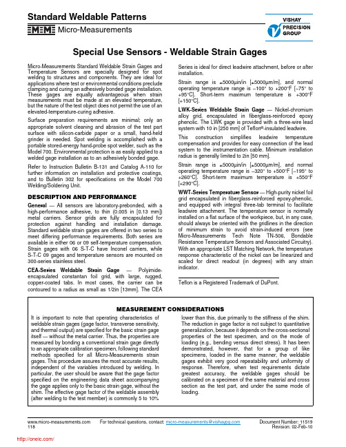
Special Use Sensors - Weldable Strain GagesStandard Weldable PatternsMicro-Measurements For technical questions, contact: micro-measurements@Document Number: 11519Micro-Measurements Standard Weldable Strain Gages and Temperature Sensors are specially designed for spot welding to structures and components. They are ideal for applications where test or environmental conditions preclude clamping and curing an adhesively bonded gage installation.These gages are equally advantageous when strain measurements must be made at an elevated temperature,but the nature of the test object does not permit the use of an elevated-temperature-curing adhesive.Surface preparation requirements are minimal; only an appropriate solvent cleaning and abrasion of the test part surface with silicon-carbide paper or a small, hand-held grinder is needed. Spot welding is accomplished with a portable stored-energy hand-probe spot welder, such as the Model 700. Environmental protection is as easily applied to a welded gage installation as to an adhesively bonded gage.Refer to Instruction Bulletin B-131 and Catalog A-110 for further information on installation and protective coatings,and to Bulletin 302 for specifications on the Model 700Welding/Soldering Unit.DESCRIPTION AND PERFORMANCEGeneral — All sensors are laboratory-prebonded, with a high-performance adhesive, to thin (0.005 in [0.13 mm])metal carriers. Sensor grids are fully encapsulated for protection against handling and installation damage.Standard weldable strain gages are offered in two series to meet differing performance requirements. Both series are available in either 06 or 09 self-temperature compensation.Strain gages with 06 S-T-C have Inconel carriers, while S-T-C 09 gages and temperature sensors are mounted on 300-series stainless steel.CEA-Series Welda le Strain Gage —Polyimide-encapsulated constantan foil grid, with large, rugged,copper-coated tabs. In most cases, the carrier can be contoured to a radius as small as 1/2in [13mm]. The CEASeries is ideal for direct leadwire attachment, before or after installation.Strain range is ±5000µin/in [±5000µm/m], and normal operating temperature range is –100° to +200°F [–75° to +95°C]. Short-term maximum temperature is +300°F [+150°C].LWK-Series Weldab le Strain Gage — Nickel-chromium alloy grid, encapsulated in fiberglass-reinforced epoxy phenolic. The LWK gage is provided with a three-wire lead system with 10 in [250 mm] of Teflon ®-insulated leadwire.This construction simplifies leadwire temperature compensation and provides for easy connection of the lead system to the instrumentation cable. Minimum installation radius is generally limited to 2in [50 mm].Strain range is ±5000µin/in [±5000µm/m], and normal operating temperature range is –320° to +500°F [–195° to +260°C]. Short-term maximum temperature is +550°F [+290°C].WWT-Series Temperature Sensor — High-purity nickel foil grid encapsulated in fiberglass-reinforced epoxy-phenolic,and equipped with integral three-tab terminal to facilitate leadwire attachment. The temperature sensor is normally installed on a flat surface of the workpiece, but, in any case,should always be oriented with the gridlines in the direction of minimum strain to avoid strain-induced errors (see Micro-Measurements Tech Note TN-506, Bondable Resistance Temperature Sensors and Associated Circuitry).With an appropriate LST Matching Network, the temperature response characteristic of the nickel can be linearized and scaled for direct readout (in degrees) with any strain indicator.Teflon is a Registered Trademark of DuPont.MEASUREMENT CONSIDERATIONSIt is important to note that operating characteristics of weldable strain gages (gage factor, transverse sensitivity,and thermal output) are specified for the basic strain gage itself — without the metal carrier. Thus, the properties are measured by bonding a conventional strain gage directly to an appropriate calibration specimen, following standard methods specified for all Micro-Measurements strain gages. This procedure assures the most accurate results,independent of the variables introduced by welding. In particular, the user should be aware that the gage factor specified on the engineering data sheet accompanying the gage applies only to the basic strain gage, without the shim. The effective gage factor of the weldable assembly (after welding to the test member) is commonly 5 to 10%lower than this, due primarily to the stiffness of the shim.The reduction in gage factor is not subject to quantitative generalization, because it depends on the cross-sectional properties of the test specimen, and on the mode of loading (e.g., bending versus direct stress). It has been demonstrated, however, that for a group of like specimens, loaded in the same manner, the weldable gages exhibit very good repeatability and uniformity of response. Therefore, when test requirements dictate greatest accuracy, the weldable gages should be calibrated on a specimen of the same material and cross section as the test part, and under the same mode of loading.Special Use Sensors - Weldable Strain GagesStandard Weldable PatternsMicro-MeasurementsDocument Number: 11519For technical questions, contact: micro-measurements@Note 1: Products with designations and options shown in bold are not RoHS compliant.GAGE PATTERN AND DESIGNATIONInsert Desired S-T-C No. in Spaces Marked XX.See Note 1RES.IN OHMS.DIMENSIONSCARRIERACTIVE GRID MATRIX Length Width Thick Length Width Length Width CEA-XX-W250A-120CEA-XX-W250A-350120 ± 0.4%350 ± 0.4%0.630.340.0050.2300.1250.440.1716.08.60.135.843.1811.24.3Most flexible and conformable pattern. T ype 326-DFV and 330-DFV flat three-conductor cable typically used to solder directly to copper-coated tabs.CEA-XX-W250C-120CEA-XX-W250C-350120 ± 0.4%350 ± 0.4%0.900.900.0050.2300.1250.440.1722.922.90.135.843.1811.24.3Tee rosette, used in biaxial stress states where directions of principal stresses are known. See W250A pattern for typical leadwire recom-mendations.LWK-XX-W250B-350350 ± 0.4%0.880.320.0050.2500.1250.620.1722.48.10.136.353.1815.74.3Wide-temperature-range linear pattern with 10 in [250 mm] pre-attached leads. Teflon insulation is pretreated for best bond to protective coatings.LWK-XX-W250D-350350 ± 0.4%1.15 1.150.0050.2500.1250.620.1729.229.20.136.353.1815.74.3Tee rosette, used in biaxial stress states where directions of principal stresses are known and a wide operating temperature range is required.WWT -TG-W200B-05050 ± 0.4% @ +75°F [+24°C]0.710.430.0050.2000.2000.520.2618.010.90.135.085.0813.16.6Easy-to-use temperature sensor that can be welded or adhesively bonded to the test structure. For standard bondable temperature sensors, see Document Number 11522, “T emperature Sensors and LST Networks.”Vishay Precision GroupDisclaimerALL PRODUCTS, PRODUCT SPECIFICATIONS AND DATA ARE SUBJECT TO CHANGE WITHOUT NOTICE.Vishay Precision Group, Inc., its affiliates, agents, and employees, and all persons acting on its or their behalf (collectively, “Vishay Precision Group”), disclaim any and all liability for any errors, inaccuracies or incompleteness contained herein or in any other disclosure relating to any product.The product specifications do not expand or otherwise modify Vishay Precision Group’s terms and conditions of purchase, including but not limited to, the warranty expressed therein.Vishay Precision Group makes no warranty, representation or guarantee other than as set forth in the terms and conditions of purchase. To the maximum extent permitted by applicable law, Vishay Precision Group disclaims (i) any and all liability arising out of the application or use of any product, (ii) any and all liability, including without limitation special, consequential or incidental damages, and (iii) any and all implied warranties, including warranties of fitness for particular purpose, non-infringement and merchantability.Information provided in datasheets and/or specifications may vary from actual results in different applications and performance may vary over time. Statements regarding the suitability of products for certain types of applications are based on Vishay Precision Group’s knowledge of typical requirements that are often placed on Vishay Precision Group products. It is the customer’s responsibility to validate that a particular product with the properties described in the product specification is suitable for use in a particular application.No license, express, implied, or otherwise, to any intellectual property rights is granted by this document, or by any conduct of Vishay Precision Group.The products shown herein are not designed for use in life-saving or life-sustaining applications unless otherwise expressly indicated. Customers using or selling Vishay Precision Group products not expressly indicated for use in such applications do so entirely at their own risk and agree to fully indemnify Vishay Precision Group for any damages arising or resulting from such use or sale. Please contact authorized Vishay Precision Group personnel to obtain written terms and conditions regarding products designed for such applications.Product names and markings noted herein may be trademarks of their respective owners.分销商库存信息: VISHAYLWK-06-W250B-350。
MBR0540T1G;MBR0540T3G;NRVB0540T1G;中文规格书,Datasheet资料

January, 2012 − Rev. 7
1
Publication Order Number: MBR0540T1/D
/
MBR0540T1G, NRVB0540T1G, MBR0540T3G, NRVB0540T3G
*For additional information on our Pb−Free strategy and soldering details, please download the ON Semiconductor Soldering and Mounting Techniques Reference Manual, SOLDERRM/D.
i F, INSTANTANEOUS FORWARD CURRENT (AMPS)
IF, INSTANTANEOUS FORWARD CURRENT (AMPS)
10
100
10
25C
1.0 TJ = 125C TJ = -40C TJ = 25C TJ = 100C 0.1 0.2 0.4 0.6 0.8 1.0 1.2 vF, INSTANTANEOUS FORWARD VOLTAGE (VOLTS)
ELECTRICAL CHARACTERISTICS
Characteristic Maximum Instantaneous Forward Voltage (Note 3) (iF = 0.5 A) (iF = 1 A) Maximum Instantaneous Reverse Current (Note 3) (VR = 40 V) (VR = 20 V) 3. Pulse Test: Pulse Width 250 ms, Duty Cycle 2.0%. IR Symbol vF TJ = 25C 0.51 0.62 TJ = 25C 20 10 Value TJ = 100C 0.46 0.61 TJ = 100C 13,000 5,000 mA Unit V
二氧化碳细胞培养箱(气套红外)使用说明书
2019-12 BC-J250二氧化碳细胞培养箱(气套红外)使用说明书上海博迅医疗生物仪器股份有限公司Shanghai Boxun Medical Biological Instrument Corp.目录1告知 (1)2安全警示标志、标识说明 (2)2.1“警告”标志 (2)2.2“注意”标志 (2)2.3标识的含义: (2)2.4设备上的标识 (3)3安全操作预防措施 (4)4产品简介 (7)4.1产品适用范围 (7)4.2产品工作原理 (7)4.3技术参数 (7)4.4产品结构 (8)5设备安装 (8)5.1安装环境 (8)5.2安装方法 (9)5.3运行前准备 (10)6操作方法 (11)6.1概述 (11)6.2工作流程 (11)6.3主界面介绍 (12)7菜单设置 (14)7.1密码设置 (14)7.2时间调整 (14)7.3报警设置 (15)7.4其他设置 (15)7.5测量修正 (16)7.6PID设置 (16)7.7恢复初值 (16)8故障排除 (17)8.1故障的诊断及简易排除 (17)8.2售后服务 (17)9维护保养 (18)9.1日常维护 (18)9.2维护方法 (18)10规格配置表 (19)11产品接线图 (20)12装箱单 (21)1告知●为保证安全使用本设备,请在使用前仔细阅读本说明书。
●务必将本说明书保存在本设备使用者方便查阅的地方。
●对本说明书规定之外的使用用途和操作方法本公司不承担安全保证。
●本使用说明书谨供设备使用者和维修人员使用,请予妥善保存。
●由于产品功能和性能的改进,引起设备的变更,恕不另行告知。
●未经本公司书面许可,不得以任何形式复制本使用说明书。
●本产品全称为:二氧化碳细胞培养箱,为了方便描述,在以下内容中简称为“培养箱”。
2安全警示标志、标识说明本说明书有重要的安全使用信息,请操作者务必遵照执行。
务必将本手册保存在本设备用户方便取用的地方。
本节所述标志内容将在设备上及本说明书内出现,旨在使您能安全正确地操作使用本设备,使使用者或任何其他人免于可能发生的伤害。
BSS84-7-F;BSS84-7;中文规格书,Datasheet资料

Symbol Min Typ Max Unit
Test Condition
BVDSS -50 ⎯ ⎯ V VGS = 0V, ID = -250µA
⎯ ⎯ -15 µA VDS = -50V, VGS = 0V, TJ = 25°C
IDSS
⎯ ⎯ -60 µA VDS = -50V, VGS = 0V, TJ = 125°C
Ciss Coss Crss
⎯ ⎯ 45 pF ⎯ ⎯ 25 pF VDS = -25V, VGS = 0V, f = 1.0MHz ⎯ ⎯ 12 pF
tD(ON) tD(OFF)
⎯ 10 ⎯ ⎯ 18 ⎯
ns VDD = -30V, ID = -0.27A, ns RGEN = 50Ω, VGS = -10V
6
3
0 -50 -25 0 25 50 75 100 125 150
TJ, JUNCTION TEMPERATURE (°C) Fig. 5 On-Resistance vs. Junction Temperature
RDS(ON), ON-RESISTANCE (Ω)
RDS(ON), NORMALIZED DRAIN-SOURCE ON-RESISTANCE (Ω)
Description and Applications
This MOSFET has been designed to minimize the on-state resistance (RDS(on)) and yet maintain superior switching performance, making it ideal for high efficiency power management applications.
RB520S-40-TP;中文规格书,Datasheet资料

RB520S-40omp onents 20736 Marilla Street Chatsworth! "# $ % ! "#www.mccsemi .comRevision: B 2012/04/11Micro Commercial Components1 of 2/Revision: B 2012/04/11Micro Commercial Componentswww.mccsemi .com2 of 22DevicePackingPart Number-TP Tape&Reel: 8Kpcs/ReelOrdering Information :***IMPORTANT NOTICE***Micro Commercial Components Corp. reserve s the right to make changes without further notice to any product herein to make corrections, modifications , enhancements , improvements , or other changes . Micro Commercial Components Corp . does not assume any liability arising out of the application or use of any product described herein; neither does it convey any license under its patent rights ,nor the rights of others . The user of products in such applications shall assume all risks of such use and will agree to hold Micro Commercial Components Corp . and all the companies whose products are represented on our website, harmless against all damages.***LIFE SUPPORT***MCC's products are not authorized for use as critical components in life support devices or systems without the express writtenapproval of Micro Commercial Components Corporation.***CUSTOMER AWARENESS***Counterfeiting of semiconductor parts is a growing problem in the industry. Micro Commercial Components (MCC) is taking strong measures to protect ourselves and our customers from the proliferation of counterfeit parts. MCC strongly encourages customers to purchase MCC parts either directly from MCC or from Authorized MCC Distributors who are listed by country on our web page cited below . Products customers buy either from MCC directly or from Authorized MCC Distributors are genuine parts, have full traceability, meet MCC's quality standards for handling and storage. MCC will not provide any warranty coverage or other assistance for parts bought from Unauthorized Sources. MCC is committed to combat this global problem and encourage our customers to do their part in stopping this practice by buying direct or from authorized distributors./分销商库存信息: MICRO-COMMERICAL-CO RB520S-40-TP。
瑞丰瑞丰W40QI35DS -DF-J-Y型号产品说明书
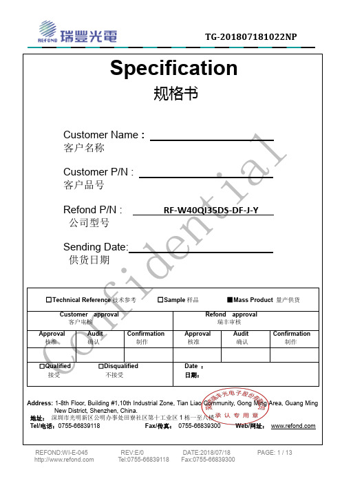
1-8th Floor, Building #1,10th Industrial Zone, Tian Liao Community, Gong Ming Area, Guang Ming栋一至八楼Web/网址:Features 特征PLCC-2 Package.垂直型表贴封装 Extremely wide viewing angle.发光角度大Suitable for all SMT assembly and solder process.适用于所有的SMT 组装和焊接工艺 Available on tape and reel.适用于载带及卷轴 Moisture sensitivity level: 3.防潮等级:3 Package:4000pcs/reel.包装:4000颗/卷RoHS compliant.RoHS 认证Description 描述The White LED which was fabricated using a blue chip and phosphors 白光LED 由芯片激发荧光粉后,混光形成。
Applications 应用Optical indicator.光学指示 Indoor display.室内显示Landscape lighting,lamp belt. 景观照明,灯带等 General use.其他适合的应用Package DimensionNOTES:1.All dimensions units are millimeters. (所有尺寸标注单位为毫米)2.All dimensions tolerances are 0.2mm unless otherwise noted. (除特别标注外,所有尺寸允许公差为±0.2毫米)Electrical / Optical Characteristics at Ts=25°C 电性与光学特性4.The above luminous flux measurement allowance tolerance ±10%. 上述光通量的测试允许公差为±10%.5. Care is to be taken that power dissipation does not exceed the absolute maximum rating of the product. 使用功率不能超过规定的最大值。
Spheros North 美国水热器和水泵产品说明书

Information concerning all warranties may be obtained by calling (734) 218-7350 ext 103 or 112. Toll free (888) 9604849.
Owner’s Responsibilities:
Seห้องสมุดไป่ตู้vice heater at the start of each season. While such maintenance may be performed by any company, improper or incorrectly performed maintenance or repair voids this warranty. Service parts including fuel nozzles, filters and overheat fuses are not covered under warranty.
B0505产品规格书

认证
UL UL UL UL
UL CE UL CE UL CE UL CE UL UL UL UL UL CE UL CE UL CE UL CE
应用范围
A_S-1W & B_LS-1W 系列产品是专门针对
B0509LS-1W B0512LS-1W B0515LS-1W B0524LS-1W A1205S-1W A1209S-1W A1212S-1W A1215S-1W B1203LS-1W B1205LS-1W B1209LS-1W B1212LS-1W B1215LS-1W B1224LS-1W A1505S-1W A1512S-1W 12 10.8-13.2
对于实际输出功率小于 0.5W 之应用场合,建议 不外接电容。
A_S-1W & B_LS-1W
A/3-2010
第 2 页 共 3 页
外形尺寸、建议印刷板图、引脚方式
外观尺寸
19.60 [0.772]
建议印刷板图
正负双路 2.10 [0.083] ∅1.00 [0.039]
6.00 [0.236] 1 2 4 5 6 2.54 [0.100]
开关频率
100%负载,输入标称电压
Vin GND
单路
REG
REG
+Vo 0V
*纹波和噪声的测试方法采用平行线测试法。具体操作方法参见产品应用笔记之电源模块的测试。 注:正负双路输出模块的负载不平衡度:±5%。
DC DC
REG
-Vo +Vo
使用注意事项
① 输出负载要求 为了确保该模块能够高效可靠的工作,使用时,其输出最小负载不能小于额定 负载的 10%。若您所需功率确实较小,请在输出端并联一个电阻,建议阻值相当于 10%额定功率,或选用我司更小功率级别的产品(A_S –W25/B_LS-W25) 。 ② 过载保护 在通常工作条件下,该产品输出电路对于过载情况无保护功能。最简单的方法是在 输入端串接一个自恢复保险丝,或在电路中外加一个断路器。 ③ 推荐电路 若要求进一步减少输入输出纹波,可在输入输出端联接一个“LC”滤波网络, 应用电路如(图 1)所示。 但应注意电感值的选取及“LC”滤波网络其自身的频率应与 DC/DC 频率错开, 避免相互干扰。并选用合适的滤波电容。若电容太大,很可能会造成启动问题。对 于每一路输出,在确保安全可靠工作的条件下,并推荐容性负载值详见(表 1) 。 ④ 输出稳压及过压保护电路 对于输出稳压、 过压及过流保护的最简单的装置是在其输入或输出端串接一个 带过热保护的线性稳压器(见图 2) 。 ⑤ 此产品不能并联使用,不支持热插拔
WS1N 精品系列产品使用说明书

为胜智控WS1N精品系列产品使用说明书--V1.1适用于以下型号:WS1N-20MR/MT-K-BWS1N-24MR/MT-K-BWS1N-28MR/MT-K-BWS1N-30MR/MT-K-BWS1N-32MR/MT-K-B产品目录第一章产品概述 (1)1.1产品概述 (1)1.2基本参数 (1)1.3使用环境及安装方式 (1)第二章产品展示 (2)2.1产品主要硬件说明 (2)2.2产品正面效果图................................2-3第三章电气设计参考.. (4)3.1电源及功耗 (4)3.2232通讯口说明 (4)3.3485通讯口说明 (5)3.4输入内部等效电路与接线说明 (6)3.5输出内部等效电路与接线说明.....................6-83.6模拟量输入说明 (8)3.7模拟量输出说明 (9)3.8产品接线图...................................9-10第四章编程参考 (11)4.1应用环境 (11)4.2元件号的分配和功能概要 (11)4.3特殊元件说明..................................11-124.4指令列表....................................12-144.5此版本不支持指令列表, (14)第五章常见问题及解决方案 (15)第六章保修条款 (15)第一章产品概述1.1产品概述·WS1N AC220V 系列,采用ARMCortex-M332位MISC 内核芯片,运算速度快,存储空间大。
·下载速度为9.6Kbps/19.2Kbps;直接使用三菱GX Developer 或者GX Works2编程、下载、调试、监视(不支持监控写入).·默认采用DC 24V 供电,可选择直接AC220V 交流供电(需联系客服改);输出继电器均不打开条件下,静态电流30MA;每打开一路增加13MA 电流,如1-24mr 输出继电器全打开后电流为160MA(3.84W)。
M57140-01;中文规格书,Datasheet资料
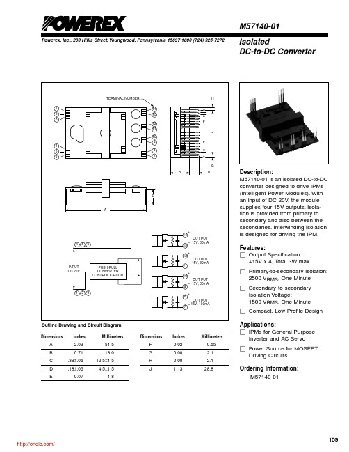
VIN
Direct Current
VO
Between Pins 10 - 9 , 12 - 11, 14 - 13,
IL = 30mA
Between Pins 8 - 7 , IL = 100mA
ILP
Between Pins 10 - 9 , 12 - 11, 14 - 13
Between Pins 8 - 7
Load Regulation Efficiency
Reg-out h
Between Pins 10 - 9 , 12 - 11, 14 - 13, IL = 0 ~ 30mA
Between Pins 8 - 7 , IL = 0 ~ 100mA Between Pins 10 - 9 , 12 - 11, 14 - 13,
IL = 30mA Between Pins 8 - 7 , IL = 100mA
Min. 18 13.5
13.5 – – –
– –
–
Typ. 20 15.0
Max. 22 16.5
Units Volts Volts
15.0 16.5
33
–
110
–
5 10
Volts mA mA %
7 12
%
70
–
%
159 /
Powerex, Inc., 200 Hillis Street, Youngwood, Pennsylvania 15697-1800 (724) 925-7272
M57140-01 Isolated DC-to-DC Converter
Absolute Maximum Ratings, VIN = 20V, Ta = 25 °C unless otherwise specified
B0540WS(丝印SF)二极管规格书(含样品申请表)

MARKING: B0520WS: SD B0530WS: SE B0540WS: SF
Maximum Ratings @Ta=25℃
Parameter Peak repetitive peak reverse voltage Working peak reverse voltage DC blocking voltage RMS reverse voltage reverse voltage (DC) Average rectified output current Forward current surge peak Power dissipation Thermal resistance junction to ambient Junction temperature Storage temperature Voltage rate of change
回访记录
□已联系确认 日期:
□已建议执行 日期:
□未发送但已下单 日期:
□已发送样品 日期:
□客户已签收 日期:
第1页共1页
B0520WS 20 ---
0.33 0.39
-75 -250 --170
B0530WS -30 --
0.36 0.45
--80 100 500 -170
B0540WS --40 --
0.510 0.62 --10 -20 170
Unit V
V μA μA pF
Conditions IR=250μA IR=500μA IR=20μA
B0540WS
Forward Characteristics
1000
100
T
=100
a
℃
T
=25℃
B0540W肖特基二极管

3.86(0.152) 3.56(0.145)
2.84(0.112) 2.54(0.100)
3.9(0.154) 3.7(0.146)
2.7(0.106) 2.6(0.102)
MECHANICAL DATA
.71(0.028) .50(0.020) .15(.006) MAX 1.35(.053) .94(.037) .135(.005) .127(.004) 0.6(.023) 0.5(.020) 1.15(.045) 1.05(.041)
第 2 页 共 2 页
.25(.010) MIN
Case: Molded plastic body Terminals: Plated leads solderable per MIL-STD-750, Method 2026 Polarity: Polarity symbols marked on case Marking: B0520LW:SD, B0530W:SE, B0540W:SF
Dimensions in millimeters and (inches)
MAXIMUM RATINGS AND ELECTRICAL CHARACTERISTICS
Maximum ratings and electrical characteristics, Single diode @TA=25C PARAMETER Peak repetitive peak reverse voltage Working peak reverse voltage DC Blocking voltage RMS Reverse voltage Average rectified output current Peak forward surge current Power dissipation Thermal resistance junction to ambient Storage temperature Voltage rate of change Electrical ratings @TA=25C PARAMETER Minimum reverse breakdomn voltage
TB05产品技术规格书(中文)-通用

扬州宝珠电器有限公司
文件编号: BZTB05-CBJG-KH01 7 温度参数表:
序号 30 35 40 45 50 55 60 65 70 75 80 85 90 动作温度 30 3℃ 35 3.5℃ 40 4℃ 45 4.5℃ 50 5℃ 55 5℃ 60 5℃ 65 5℃ 70 5℃ 75 5℃ 80 5℃ 85 5℃ 90 5℃ 复位温度 ≥20℃ ≥25℃ ≥30℃ ≥33℃ ≥35℃ 42 6℃ 45 8℃ 48 10℃ 50 12℃ 53 14℃ 55 15℃ 60 15℃ 65 15℃ 序号 95 100 105 110 115 120 125 130 135 140 145 150 155 动作温度 95 5℃ 100 5℃ 105 5℃ 110 5℃ 115 5℃ 120 5℃ 125 5℃ 130 5℃ 135 5℃ 140 5℃ 145 5℃ 150 5℃ 155 5℃
文件编号: BZTB05-CBJG-KH01
页码:4-3
3.11 抗压试验:产品应能承受 100N 静压力 1min。 3.7,3.8,3.9,3.10,3.11 项试验后应满足下列条件: a.断开温度变化应在初期值的+7℃以内; b.接触电阻应在 100mΩ以下; c.外形应无明显变形; d.导线无开裂损伤。 4 寿命 产品在额定电压、电流、功率因数为 0.7 的条件下(在交流电路中,电压与电流之间的相位差(Φ)的余弦 叫做功率因数,用符号 cosΦ表示,在数值上,功率因数是有功功率和视在功率的比值,即 cosΦ=P/S),外加 热源使其动作 6000 次,应满足下面条件: a.断开温度变化应在初始值的+5℃以内; b.接触电阻应在 100mΩ以下; 继续试验至 10000 次后能动作。 5 其它事项: 5.1 断开温度检测的升温速率应控制为 1℃/1min; 5.2 使用过程中产品不能承受强烈冲击力及压迫力; 5.3 型号规格说明: 5.3.1 常闭型 TB05-BB5D——塑壳产品型号 XXX℃——额定断开温度 5.3.2 常开型 TB05-KA5D——塑壳产品型号 XXX℃——额定断开温度 6 获取证书: VDE 证书号:40024884 CQC 证书号:CQC06002017310 CB 证书号:CN8029 UL 证书号:E258703 ISO9001 证书号:0105Q1274ROS/3200 TB05-KA1D——铁壳产品型号 XXX℃——额定断开温度 TB05-BB1D——铁壳产品型号 XXX℃——额定断开温度
ABB温度传感器说明书
警告 — 人体损伤 大于等于 DN 450 的设备检查螺钉(排放冷凝液)有可能处于受压状态。 液体喷出会造成严重伤害。 松开检查螺钉前必须对管路卸压。 检修工作必须由专业受训人员完成。 • 拆除设备前必须对设备、相邻管路和容器卸压。 • 打开设备前检查测量物料是否具有危险性。设备中可能仍残留部分危险物 料,打开设备时有可能泄漏造成危害。 • 以下各项内容属于操作人员责任,应定期予以检查: - 压力装置的压力壁/压力衬垫 - 测量功能 - 气密性 - 磨损(腐蚀)
警告 —<人体损伤> 此符号与“警告”信息表示存在潜在的危险。如不加以避免,可能造成严重 的伤亡事故。
小心 —<轻微损伤> 此符号与“小心”信息表示存在潜在的危险。如不加以避免,可能造成轻微 损伤事故。此符号也可用于财产损失警告。
注意 —<财产损失> 此符号表示可能造成财产损失!如不加以避免,设备或现场其他财产有可 能遭受损失。
重要信息 此符号表明操作提示或特别有用的信息,与危险或者财产损失无关。
Ol/TSP_ZA
SensyTemp TSP1X8
8
1.6
1.6.1
铭牌
铭牌(标准)
1 2 3 4 5 6
产品类型 变送器生产商 产品名称 序列感器参数 温度范围 温变器类型 保护等级 注意产品文档
1.9
运输安全提示
注意以下信息: • 设备运输过程中切勿受潮,按要求包装设备。 • 设备包装应考虑运输过程的颠簸振动,例如:采用气垫保护包装。 开箱后立即检查设备,是否有由于不当运输造成的损坏。将运输损坏记录在 运输单据上,在安装前立即向运输公司提出所有赔偿要求。
1.10
安装安全提示
注意以下信息: • 所有法兰连接必须符合最大扭矩要求。 • 传感器安装应避免不良机械张力(扭转、弯曲)。 • 使用共面对接法兰安装法兰型设备。 • 传感器安装应符合使用要求,配备合适的密封件。 • 拧紧法兰螺栓、螺母,消除管路振动带来的不良影响。
MORNSUN B05_XT-2WR3 Series DC DC Converter Datashe

2W isolated DC-DC converterFixed input voltage,unregulated single outputPatent Protection RoHSFEATURES●Continuous short-circuit protection ●No-load input current as low as 8mA●Operating ambient temperature range:-40℃to+105℃●High efficiency up to 86%●Compact SMD package●I/O isolation test voltage 1.5k VDC●Industry standard pin-outB05_XT-2WR3series are designed for use in distributed power supply systems and especially suitable in applications such as pure digital circuits,low frequency analog circuits,relay-driven circuits and data switching circuits.Selection GuideCertificationPart No.Input Voltage (VDC)OutputFull Load Efficiency (%)Min./Typ.Capacitive Load(µF)Max.Nominal (Range)Voltage (VDC)Current(mA)Max./Min.--B0503XT-2WR35(4.5-5.5) 3.3400/4074/782400B0505XT-2WR35400/4080/842400B05X7XT-2WR37286/2980/841000B0509XT-2WR39222/2281/851000B0512XT-2WR312167/1781/85560B0515XT-2WR315133/1382/86560B0524XT-2WR32483/882/86220Input SpecificationsItemOperating ConditionsMin.Typ.Max.UnitInput Current(full load /no-load)5VDC input3.3VDC output--339/8357/--mA5VDC/7VDC output --477/8500/--9VDC/12VDC output --471/8494/--15VDC/24VDC output--466/8488/--Reflected Ripple Current*--15--Surge Voltage (1sec.max.)-0.7--9VDCInput Filter Capacitance filter Hot PlugUnavailableNote:*Reflected ripple current testing method please refer to DC-DC Converter Application Note for specific operation.Output SpecificationsItemOperating ConditionsMin.Typ.Max.UnitVoltage AccuracySee output regulation curve (Fig.1)Linear RegulationInput voltage change:±1%3.3VDC output----±1.5--5VDC/7VDC/9VDC/12V DC/15VDC/24VDC output ----±1.2Load Regulation10%-100%load3.3VDC output --1020%5VDC/7VDC output--9159VDC output--81012VDC/15VDC output --71024VDC output--610Ripple &Noise*20MHz bandwidth --75200mVp-p Temperature Coefficient Full load--±0.02--%/℃Short-circuit ProtectionContinuous,self-recoveryNote:*The“parallel cable”method is used for ripple and noise test,please refer to DC-DC Converter Application Notes for specific information. General SpecificationsItem Operating Conditions Min.Typ.Max.UnitIsolation Input-output electric strength test for1minute with aleakage current of1mA max.1500----VDC Insulation Resistance Input-output resistance at500VDC1000----MΩIsolation Capacitance Input-output capacitance at100kHz/0.1V--20--pFOperating Temperature Derating when operating temperature≥85℃,(seeFig.2)-40--105℃Storage Temperature-55--125Case Temperature Rise Ta=25℃--25--Storage Humidity Non-condensing5--95%RHReflow Soldering Temperature*Peak temp.Tc≤245℃,maximum durationtime≤60s over217℃Vibration10-150Hz,5G,0.75mm.along X,Y and Z Switching Frequency Full load,nominal input voltage--220--kHz MTBF MIL-HDBK-217F@25℃3500----k hours Moisture Sensitivity Level(MSL)IPC/JEDEC J-STD-020D.1Level1Note:*See also IPC/JEDEC J-STD-020D.1.Mechanical SpecificationsCase Material Black plastic;flame-retardant and heat-resistant(UL94V-0)Dimensions13.20x11.40x7.25mmWeight 1.4g(Typ.)Cooling Method Free air convectionElectromagnetic Compatibility(EMC)Emissions CE CISPR32/EN55032CLASS B(see Fig.4for recommended circuit) RE CISPR32/EN55032CLASS B(see Fig.4for recommended circuit)Immunity ESD IEC/EN61000-4-2Air±8kV,Contact±6kV perf.Criteria B Typical Characteristic Curves3.3VDC output5VDC/7VDC/9VDC/12VDC/15VDC/24VDC outputFig.1Design Reference1.Typical applicationInput and/or output ripple can be further reduced,by connecting a filter capacitor from the input and/or output terminals to ground as shown in Fig.3.Choosing suitable filter capacitor values is very important for a smooth operation of the modules,particularly to avoid start-up problems caused by capacitor values that are too high.For recommended input and output capacitor values refer to Table 1.Vin0VDCCinDC CoutFig.3Table 1:Recommended input and output capacitor valuesVin Cin Vo Cout5VDC 4.7µF/16V3.3VDC/5VDC 10µF/16V ----7VDC/9VDC4.7µF/16V ----12VDC 2.2µF/25V ----15VDC 1µF/25V ----24VDC0.47µF/50V2.EMC compliance circuitFig.4EmissionsC1,C24.7µF /16VC3Refer to the Cout in Fig.3CY 270pF/2kV LDM6.8µH3.For additional information,please refer to DC-DC converter application notes on80O u t p u t P o w e r P e r c e n t (%)Ambient Temp.()℃Temperature Derating CurveSafe Operating AreaFig.2Dimensions and Recommended Layout Tape and Reel InfoNotes:1.For additional information on Product Packaging please refer to .Tube Packaging bag number:58210024,RollPackaging bag number:58200054;2.If the product is not operated within the required load range,the product performance cannot be guaranteed to comply with allparameters in the datasheet;3.The maximum capacitive load offered were tested at input voltage range and full load;4.Unless otherwise specified,parameters in this datasheet were measured under the conditions of Ta=25℃,humidity<75%RH with nominalinput voltage and rated output load;5.All index testing methods in this datasheet are based on our company corporate standards;6.We can provide product customization service,please contact our technicians directly for specific information;7.Products are related to laws and regulations:see"Features"and"EMC";8.Our products shall be classified according to ISO14001and related environmental laws and regulations,and shall be handled byqualified units.MORNSUN Guangzhou Science&Technology Co.,Ltd.Address:No.5,Kehui St.1,Kehui Development Center,Science Ave.,Guangzhou Science City,Huangpu District,Guangzhou,P.R.China Tel:86-20-38601850Fax:86-20-38601272E-mail:***************。
X50和X40纤维类型气体吸收氧氣筛选器说明书
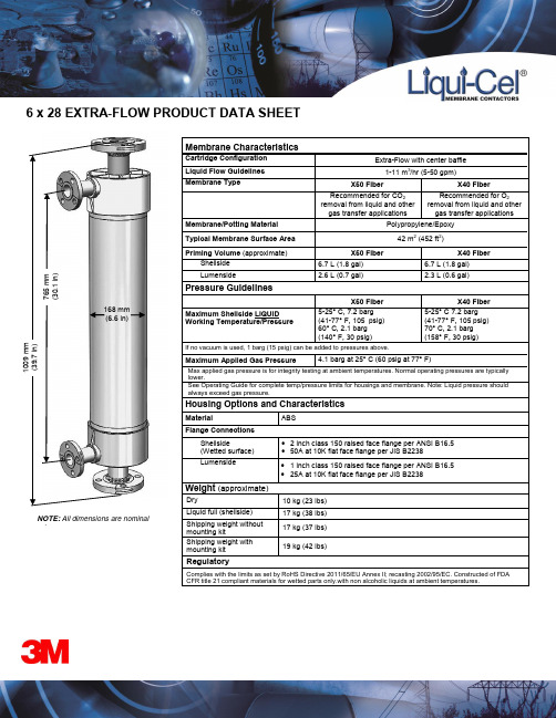
6 x 28 EXTRA-FLOW PRODUCT DATA SHEETNOTE: All dimensions are nominalvalues168 mmIndustrial Business Group Membranes Business Unit 13840 South Lakes Drive Charlotte, North Carolina 28273 USAPhone: +1 704 587 8888Fax: +1 704 587 86103M Deutschland GmbHMembranes Business UnitÖhder Straße 2842289 WuppertalGermanyPhone: +49 202 6099 - 658Fax: +49 202 6099 - 7503M Japan Ltd.Membranes Business Unit6-7-29, Kita-Shinagawa,Shinagawa-ku, Tokyo | 141-8684JapanPhone: +81 3 6409 5732Fax: +81 3 6409 58276 x 28 EXTRA-FLOW PRODUCT DATA SHEET Technical Information: The technical information, recommendations and other statements contained in this document are based upon tests or experience that 3M believesare reliable, but the accuracy or completeness of such information is not guaranteed.Product Use:Many factors beyond 3M’s control and uniquely within user’s knowledge and control can affect the use and performance of a 3M product in a particularapplication. Given the variety of factors that can affect the use and performance of a 3M product, user is solely responsible for evaluating the 3M product and determiningwhether it is fit for a particular purpose and suitable for user’s method of application.Warranty, Limited Remedy, and Disclaimer: Unless an additional warranty is specifically stated on the applicable 3M product packaging or product literature, 3M warrantsthat each 3M product meets the applicable 3M product specification at the time 3M ships the product. 3M MAKES NO OTHER WARRANTIES OR CONDITIONS, EXPRESSOR IMPLIED, INCLUDING, BUT NOT LIMITED TO, ANY IMPLIED WARRANTY OR CONDITION OF MERCHANTABILITY OR FITNESS FOR A PARTICULAR PURPOSEOR ANY IMPLIED WARRANTY OR CONDITION ARISING OUT OF A COURSE OF DEALING, CUSTOM OR USAGE OF TRADE. If the 3M product does not conform tothis warranty, then the sole and exclusive remedy is, at 3M’s option, replacement of the 3M product or refund of the purchase price.Limitation of Liability: Except where prohibited by law, 3M will not be liable for any loss or damage arising from the 3M product, whether direct, indirect, special, incidentalor consequential, regardless of the legal theory asserted, including warranty, contract, negligence or strict liability.3M, Membrana, and Liqui-Cel are trademarks of 3M Company. All other trademarks are the property of their respective owners.© 2015 3M Company. All rights reserved. (D67 Rev 16)。
Fisherbrand LVR50 Series 双线液位传感器说明书

0.701 (2.3)
Aluminum
LVR52-PP
708
LVR53
952
0.6 (2) 0.9 (3)
0.701 (2.3) 1.00 (3.3)
Polypropylene
Aluminum
K
LVR53-PP
852
0.9 (3)
1.00 (3.3)
Polypropylene
LVR54
1096
1.2 (4)
Dia. 52 (2.1)
4.76 (0.1875)
13 (0.5)
1/2 FNPT
117 (4.6)
156 (6.1)
Polypropylene Head
B 6.35 (0.25)
70 (2.7) C (Indicating Length, see chart below) A (Overall Length Dimension, see chart below)
APPLICATION VARIABLES
Liquid
Variable
General Purpose Intrinsically Safe Conductive Non-conductive Δ Conductivity Foam Vapors Δ Gas Density Contact Clean Dirty Non-coating Ambient Pressure Low Pressure Medium Pressure Coating Non-contact Integral Relay Vacuum
6WDPIRUG &7
&$1$'$ ZZZRPHJDFD /DYDO 4XHEHF 7&20(*$
WS-70说明书

WS-70说明书1、用途:WS-7100智能温湿度控制器广泛应用于电力电子行业,以及需要对温度和湿度进行综合控制的场合。
主要用于电力系统中的开关柜、中置柜、箱式变电站等设备。
该产品性能稳定,使用寿命长。
能够保障电气设备长期安全可靠的运行。
2、产品特点:④采用进卫全数字是度传感器,堆能稳定,在命长(2)采用美国进行芯片做控制,可靠性好。
(3)具有WATCHDO6功能,保障电路运行可靠。
(4)采用LCD做显示,人机界面友好。
(5)可以同时检测两路环境温度和湿度,并做相应的加热控制。
(6)用户可以根据实际情况自己设定温度和湿度起控点。
(7)用户可以根据情况选择手动强制加热或自动运行。
(8)具有传感器、加热器自检报警功能,确保系统可靠工作。
3、技术参数:温度显示范围:-9~99℃精度士1℃湿度显示范围:0~99%RH精度士5%RH工作环境温度:-25C~55℃工作环境湿度:≤95%RH温度设定范围:+3℃~40℃湿度设定范围:40%~90%RH工作电压:AC110V/220V工频耐压;2Kv/1min触点容量:205V/AC5A功率消耗:≤10T外形尺寸(mm):96?8?8开孔尺寸(mm):91?44、工作原理说明:WS-7100温湿度控制器带两路温湿度传感器。
用户按照连接线图连接传感WS-7100温湿度控制器带两路温湿度传感器。
用户按照连接线图连接传感器、加热器和报警器。
环境温度和湿度信息通过传感器转为数字信号传到主机,通过内部微处理器逻辑判断和处理后在LCD面板上显示。
当l路混度高于设置的混度上限值时,控制器启动1通道加热器工作,当湿度低于设定的湿度下限时,l通道加热器停止工作。
- 1、下载文档前请自行甄别文档内容的完整性,平台不提供额外的编辑、内容补充、找答案等附加服务。
- 2、"仅部分预览"的文档,不可在线预览部分如存在完整性等问题,可反馈申请退款(可完整预览的文档不适用该条件!)。
- 3、如文档侵犯您的权益,请联系客服反馈,我们会尽快为您处理(人工客服工作时间:9:00-18:30)。
SURFACE MOUNT SCHOTTKY BARRIER RECTIFIERFeatures• Low Forward Voltage Drop• Guard Ring Construction for Transient Protection • High Conductance• Lead Free By Design/RoHS Compliant (Note 3) • "Green" Device (Note 4)Mechanical Data• Case: SOD-323• Case Material: Molded Plastic, "Green" Molding Compound.UL Flammability Rating Classification 94V-0• Moisture Sensitivity: Level 1 per J-STD-020D• Polarity: Cathode Band• Terminals: Finish - Matte Tin Annealed Over Alloy 42leadframe. Solderable per MIL-STD-202, Method 208 • Marking Information: See Page 2• Ordering Information: See Page 2• Weight: 0.004 grams (approximate)Top ViewMaximum Ratings@T A = 25°C unless otherwise specifiedSingle phase, half wave, 60Hz, resistive or inductive load.For capacitance load, derate current by 20%.Characteristic Symbol Value UnitPeak Repetitive Reverse Voltage Working Peak Reverse Voltage DC Blocking Voltage V RRMV RWMV R40 VRMS Reverse Voltage V R(RMS)28 V Average Rectified Output Current I O0.5 ANon-Repetitive Peak Forward Surge Current8.3ms single half sine-wave superimposed on rated load I FSM3 A Thermal CharacteristicsCharacteristic Symbol Value Unit Power Dissipation (Note 1) P D235 mW Typical Thermal Resistance Junction to Ambient (Note 1) RθJA426 °C/W Operating and Storage Temperature Range T J, T STG-40 to +125 °CElectrical Characteristics@T A = 25°C unless otherwise specifiedCharacteristic Symbol Min Typ Max Unit Test Condition Reverse Breakdown Voltage (Note 2) V(BR)R40 ⎯⎯V I R = 1mAForward Voltage V F⎯285480300550mVI F = 10mAI F = 500mAReverse Current (Note 2) I R ⎯⎯1.02.035μAμAV R = 10VV R = 30VTotal Capacitance C T ⎯⎯12520⎯⎯pFpFV R = 0V, f = 1.0MHzV R = 10V, f = 1.0MHzNotes: 1. Part mounted on FR-4 PC board with recommended pad layout, which can be found on our website at /datasheets/ap02001.pdf.2. Short duration pulse test used to minimize self-heating effect.3. No purposefully added Lead.4. Diodes Inc.'s "Green" policy can be found on our website at /products/lead_free/index.php.Please click here to visit our online spice models database.10100V, INSTANTANEOUS REVERSE VOLTAGE (V)Fig. 2 Typical Reverse CharacteristicsRI,INSTANTANEOUSFORWARDCURRENT(mA)FV, INSTANTANEOUS FORWARD VOLTAGE (V)Fig. 1 Typical Forward CharacteristicsF100C,TOTALCAPACITANCE(pF)TV, DC REVERSE VOLTAGE (V)Fig. 3 Total Capacitance vs. Reverse VoltageR0.250.50050100I,AVE150RAGEFORWARDCURRENT(A)F(AV)T, TERMINAL TEMPERATURE (C)Fig. 4 Forward Current Derating CurveT°0.751.02575125Ordering Information(Note 5)Part Number Case PackagingB0540WS-7 SOD-323 3000/Tape & ReelNotes: 5. For packaging details, go to our website at /datasheets/ap02007.pdf.Marking InformationSF SF = Product Type Marking CodePackage Outline DimensionsSuggested Pad LayoutIMPORTANT NOTICEDiodes Incorporated and its subsidiaries reserve the right to make modifications, enhancements, improvements, corrections or other changes without further notice to any product herein. Diodes Incorporated does not assume any liability arising out of the application or use of any product described herein; neither does it convey any license under its patent rights, nor the rights of others. The user of products in such applications shall assume all risks of such use and will agree to hold Diodes Incorporated and all the companies whose products are represented on our website, harmless against all damages.LIFE SUPPORTDiodes Incorporated products are not authorized for use as critical components in life support devices or systems without the expressed written approval of the President of Diodes Incorporated.SOD-323 Dim Min Max A 0.25 0.35 B 1.20 1.40 C 2.30 2.70 H 1.60 1.80 J 0.00 0.10 K 1.0 1.1 L0.20 0.40 M 0.10 0.15α0° 8°All Dimensions in mmDimensions Value (in mm)Z 3.75 G 1.05 X 0.65 Y 1.35 C 2.40分销商库存信息: DIODESB0540WS-7。
