LTC4265:以太网供电(PoE)接口控制器
KSZ8795 Evaluation Board 用户指南说明书

KSZ8795-POE-EVAL Board(KSZ8795CLX+KSZ9031RNX)Demo Evaluation Board User’s GuideKSZ8795 Family Integrated 5-port Managed Switch with 4 10/100 Copper Ports and Port 5 Gigabit port Rev 1.0 January 2015Table of contents1.0 Introduction (4)2.0 Features (4)3.0 Evaluation Kit Contents (4)4.0 Hardware Description (5)4.1 Strap in Mode (6)4.2 Feature Setting Jumpers (7)4.3 SPI Mode (8)4.4 10/100 Ethernet Ports (8)4.4 10/100/1000 Gigabit Ports (8)4.5 LED indicators (9)5.0 Software Tools Description (10)5.1 Introducing Application Software Tools (10)5.2 Window Driver Installation First (10)5.3 Installation Application Software Tools (13)5.4 DOS SPI Tool (15)5.5 Window SPI Software Tool (16)5.6 LinkMD Software Tool (17)6.0 Reference Documents (19)7.0 Bill of Material (19)8.0 Schematics (19)List of Figures and TablesFigure 1 KSZ8795-POE-EVAL Board (5)Figure 2 KSZ8795-POE-EVAL Board Block Diagram (6)Table 1 General Setting Jumpers (7)Table 2 Power Setting Jumpers (7)Table 3 LED Modes (9)Revision History1.0 IntroductionThe KSZ8795 family is Micrel Operations new generation integrated 5-port switch with Gigabit up-link. The KSZ8795CLX is one of KSZ8795 family. KSZ8795CLX contains four MAC/PHYs for four copper ports and one GMAC5 interface with configurable GMII/RGMII/MII/RMII interfaces. The device had been designed with cost sensitive systems in mind but still offers a multitude of new features such as port based security ACL filtering, 802.1az EEE, LinkMD and so on. Also support port and tag based VLAN; QoS priority; SPI and MDC/MDIO interfaces for the registers access. The KSZ8795 family is an excellent choice in broadband gateway applications, integrated broadband router applications, industrial automatic, automotive, etc. fields and as a standalone switch. The KSZ8795-POE-EVAL board is designed to allow the user to experience Gigabit up-link with KSZ9031 Gigabit PHY to Gigabit port of any processor board directly, and can provide PoE PSE power to other four ports. Other rich feature set can be evaluated on this board. The evaluation board is highly configurable and easy to use.2.0 Features∙Micrel KSZ8795 Integrated 5-port 10/100 Managed Ethernet Switch∙ 4 RJ-45 Jacks for 10/100Base-T/TX Ethernet LAN with Corresponding Isolation Magnetics. ∙Auto MDI/MDIX on All Ports.∙Port 5 SW5-RGMII hook-up with a KSZ9031RNX GPHY and provide a Gigabit port.∙Easily set to different VDDIO of 3.3V, 2.5V and 1.8V by jumpers.∙ 1 USB Port Interface Configurable to Emulate an SPI Interface for all registers access by using Window GUI and DOS based software tools.∙ 2 LEDs per Port with 5 LED sets to indicate the Status and Activity for 4 fast Ethernet ports and1 Gigabit port.∙The board powered can be used by a 12V DC power supply.3.0 Evaluation Kit ContentsThe KSZ8795-POE-EVAL Evaluation kit includes the following:∙KSZ8795-POE-EVAL Evaluation Board Rev. 1.x∙KSZ8795-POE-EVAL Ev aluation Board User’s Guide Rev 1.x∙Micrel SPI Configuration Software tools∙KSZ8795-POE-EVAL Evaluation Board Schematics and BOM∙KSZ8795-POE-EVAL PCB file, Gerber file and IBIS model∙The software, reference schematics and other design information will be found in the Design Kit (Design Package) of the KSZ8795 Ethernet switch products on Micrel website.(Contact your Micrel FAE for the latest schematic).∙One 12V DC power supply.∙The USB cable is not included.4.0 Hardware DescriptionThe KSZ8795-POE-EVAL evaluation board is in a compact form factor and can sit on a bench near a computer with USB connector. There are two options for configuration: strap in mode; SPI mode and Strap-in mode that is easily done with on board jumper options. SPI mode is accomplished through a built in USB port interface. You can configure the KSZ8795 device on board by the USB port. Using Micrel SPI software and your PC, you can access the KSZ8795’s full feature set registers by the USB to SPI interface. The board also features RGMII to hook up a KSZ9031RNX as a Gigabit uplink for Gigabit port 5.The KSZ8795-POE-EVAL evaluation board is easy to use. There are programmable LED indicators for link and activity on all ports and a power LED. A manual reset button allows the user to reset the board without removing the power plug. A standard 12VDC power supply can be used by the power jack so that the user can supply power from any 110-240 Volt AC wall or bench socket.Figure 1 KSZ8795-POE-EVAL BoardFigure 2 KSZ8795-POE-EVAL Board Block Diagram4.1 Strap in ModeStrap in configuration mode is the quickest and easiest way to get started. In the default mode, the KSZ8795 acts as a stand-alone 4 port switch and one RGMII up-link. The user has to simply set the board’s configuration jumpers to the desired settings and apply power to the board. The user can also change jumper settings while power is applied to the board and press the convenient manual reset button for the new settings to take effect. Note that even if there is no external strap in values are set, internal pull up and pull down resistors will set the KSZ8795 default configuration. Section 4.1.1 covers each jumper on the board and describes its function.The KSZ8795 will start automatically after power up or reset.4.2 Feature Setting JumpersThe evaluation board provides jumpers to allow the user to easily set strap in configurations for the KSZ8795. Tables below describe the jumpers and their functions in the open or closed state.Table 1 General Setting JumpersTable 2 Power Setting Jumpers4.3 SPI ModeFrom SPI interface to the KSZ8795, use a USB to SPI converter that allows accessing all of the KSZ8795 features and registers. The user can easily access the SPI interface using a computer connected to the evaluation board’s USB port interface. Micrel provides a Windows GUI based program for the user to evaluate the KSZ8795’s full feature set. KSZ8795’s SP I interface will be able to access all static MAC table, the VLAN table, dynamic MAC address table, the MIB counters and all enhanced features.To prepare the KSZ8795CLXD-EVAL board for SPI mode configuration follow these steps:1. Copy the Micrel provided SPI interface software on your computer.2. KSZ8795-POE-EVAL board is fixed at SPI slave mode.3.Connect the computer’s USB port to the KSZ8795CLXD-EVAL board with a USB port cable.4.Connect the 12V DC power supply to J7 of the KSZ8795-POE-EVAL board.5.Open the Windows and navigate to the directory where the Window SPI file is stored. Click itsicon to invoke the software.6.Program the desired settings using the Micrel SPI interface software. See the softwareoperation description section for details.4.4 10/100 Ethernet PortsThere are five 10/100 Ethernet ports on the KSZ8795-POE-EVAL board. The ports J1, J2, J3 and J4 are the standard RJ45 connectors and using CAT-5 cables. Each port can be used as either an uplink or downlink. All ports support Auto-MDI/MDIX, so there is no need for cross over cables. J1 = RJ45 connector for port 1J2 = RJ45 connector for port 2J3 = RJ45 connector for port 3J4 = RJ45 connector for port 4JM1, JM2, JM3, JM4 and JS1, JS2, JS3, JS4 special connectors for Automotive used only.4.4 10/100/1000 Gigabit PortsThere is one KSZ9031RNX with 10/100/1000 Ethernet ports on the KSZ8795-POE-EVAL board. The ports RJ1 is the standard RJ45 connectors for port 5 and can connect to one Gigabit port of a processor platform by using CAT-5 cables. The port supports Auto-MDI/MDIX, so there is no need for the cross over cables.RJ1 = RJ45 connector for port 54.5 LED indicatorsEthernet Port LEDsThere are four columns of LED indicators on the board, one column for each of the four ports. The LED indicators are programmable to two different modes. You can program the LED mode through Register 11 bits [5:4]. The mode definitions are shown in Table below. There are two LEDs per port. The naming convention is “LEDx_y”, where “x” is the port number, and “y” is the number of the LED for that port.Table 3 LED ModesLED1_y are assigned to port 1LED2_y are assigned to port 2LED3_y are assigned to port 3LED4_y are assigned to port 4Gigabit Port LEDThe board also has a Gigabit port LED D3 to indicate the link-up speed for port 5.Green Color: 1G LinkRed Color: 100M LinkOrange Color: 10M LinkPower LEDThe board also has a power LED D7 for the 3.3V power supply. D7 LED indicates Power on and off.5.0 Software Tools Description5.1 Introducing Application Software ToolsThe Design Kit provides some software tools to support SPI access for all registers andMDC/MDIO access for MIIM registers. The installation file is located folders in the software tool directory within subdirectory of Window SPI_MDIO_Tools, this file name is MicrelSwitchPhyTool_x.xx.msi.5.2 Window Driver Installation FirstBefore use the Window based application software tool, the support drivers need to be installed to PC/Laptop first and this installation is just one times only. When connect one standard USB cable with type A and type B connectors between the evaluation board and PC computer first time, the Found New Hardware Wizard window will pop-up and then follow the instructions step by step as below.. Choose ‘No, not this time’ radio button and click the ‘Next’ button.Choose the ‘Install from a list or specific location (Advanced)’ radio button and click the ‘Next’ button.Click the ‘Include this location in the search’ check box, and use ‘Browse’ button to select the‘C:\MicrelEthernetChipConfig\D2XXDriver\CDM 2.02.04 WHQL Certified’ directory and click the ‘Next’ button. The window will install the drivers from this location.Click ‘Finish’ button. The Window will install another driver called ‘USB Serial Converter B’. After the drivers installed, Window Device Manager will show ‘USB Serial Converter A’ and ‘USB Serial Converter B’ as below figure. That means the installation successful.5.3 Installation Application Software ToolsIn the Design Kit, the installation file is located folders in the software tool directory within subdirectory of Window SPI_MDIO_Tools, this file name is MicrelSwitchPhyTool_x.xx.msi. Double click this file name, an installation Window will pop-up and then follow the instructions step by step as below.In this pop-up Window, this application software tools can be assigned to default Micrel directory in above window shown or is assigned to a specified folder what you want. Click ‘Next’ button, next Window will pop-up as below.Click ‘Next’ button to start the installation.Click ‘Close’ button to finish the installation. All application software tools are installed into the default Micrel directory or assigned directory in installation as below.5.4 DOS SPI ToolThis is a simple and powerful tool to access all register. The tool located in the default or assigned folder in the installation. There is an USBSPI.exe file which can be executed directly by clicking its icon. Before run the software tool, the SPI jumper setting should follows Table 5 in 4.3 SPI mode section and USB cable is plugged in both KSZ8795-POE-EVAL board and PC/Laptop. After click its icon, a DOS Window will pop up as follow:T ype a ‘help’ and press Enter, all commands will display as follows,For Read or Write registers, reg is the offset address of the register, value is Hex number.The ‘run file’ command can execute multiple commands by a script file, the script file is a .txt file which can be created by any edit tools.run xxxx.txt //will run the .txt script file.5.5 Window SPI Software ToolThis is a powerful tool to access all register. The tool located in the default or assigned folder in the installation. There is a MicrelSwitchConfigApp.exe file which can be executed directly by clicking its icon.Before run the software tool, the SPI jumper setting should follows Table 5 in 4.3 SPI mode section and USB cable should be plugged in both KSZ8795CLXD-EVAL board and PC/Laptop. After click its icon, a GUI Window will pop up as follow:The default is SPI interface to do switch configuration. From the device selection window to select any devices then press ‘Continue’ button or click ‘Continue’ button directly, the software tool can detect devices automatically. A control Window will be pop up as follow.All register can be read/ written in the window.The control Window includes all application registers, static MAC table, VLAN table, dynamic table and MIB counters that are supported by SPI. The software can save and open the configuration file as a back-up.5.6 LinkMD Software ToolThis is a simple and powerful tool to test Micrel LinkMD feature. The tool is in the installation folder. There is a LinkMDUSB.exe file which can be executed directly by clicking its icon.After click the icon of this executed file, a GUI Window will pop up as follow:Select one part and clik ‘Next’ button, using SPI interface and clik ‘Next’ button again, pop up a test windown as below:An example for CAT-5 cable diagnostic with open on port 1, just clic k ‘TEST’ button, a test result shows as below.The test result shows both MDIX mode for pair 3-6 and MDI mode for 1-2 pair. The detail LinkMD diagnostic testing configuration is described in the datasheet.6.0 Reference DocumentsKSZ8795CLX Data Sheets (Contact Micrel for Latest Datasheet), KSZ8795 Design Package includes all design information as a Design kit. The Design Kit will be found on Micrel website (Contact Micrel for the updates).7.0 Bill of MaterialPlease see the detail BOMs in the BOM folder of the hardware design package for theKSZ8795-POE-EVAL Boards.8.0 SchematicsPlease see the schematics of the evaluation board and reference design in the schematicsfolder of the hardware design package (Design kit) for the KSZ8795-POE-EVAL Board. Magnetics Vendors:See the datasheets for the recommendation.MICREL, INC. 1849 FORTUNE DRIVE SAN JOSE, CA 95131 USA TEL +1 (408) 944-0800 FAX +1 (408) 474-1000 WEB http:/ The information furnished by Micrel in this data sheet is believed to be accurate and reliable. However, no responsibility is assumed by Micrel for its use. Micrel reserves the right to change circuitry and specifications at any time without notification to thecustomer.Micrel Products are not designed or authorized for use as components in life support appliances, devices or systems where malfunction of a product can reasonably be expected to result in personal injury. Life support devices or systems are devices or systems that (a) are intended for surgical implant into the body or (b) support or sustain life, and whose failure to perform can be reasonably expected to result in a signi ficant injury to the user. A Purchaser’s use or sale of Micrel Products for use in life support appliances, devices or systems is a Purchaser’s own risk and Purchaser agrees to fully indemnify Micrel for any damagesresulting from such use or sale.© 2015 Micrel, Incorporated.。
ltc2954的用法

ltc2954的用法摘要:1.简介2.特性3.应用领域4.使用方法4.1 接线4.2 配置4.3 操作5.常见问题及解决方案6.总结正文:【简介】LTC2954 是德州仪器(Texas Instruments)公司生产的一款高精度、低漂移的电压基准芯片,具有4 路输出,广泛应用于各种电子设备中,提供精确稳定的电压参考。
【特性】LTC2954 具有以下特性:1.4 路输出,输出电压分别为2.5V、1.25V、0.625V 和0.313V;2.低漂移,典型值为±2ppm/°C;3.高精度,典型值为±0.02%;4.低噪声,典型值为1μVp-p;5.宽工作电压范围,1.8V 至5.5V;6.紧凑型5 引脚SC70 封装。
【应用领域】LTC2954 电压基准芯片广泛应用于通信、工业控制、医疗设备、仪器仪表等领域,为这些设备提供精确稳定的电压参考。
【使用方法】【接线】使用时,将LTC2954 的VCC 引脚连接到1.8V 至5.5V 电源,GND 引脚连接到地,然后将输出引脚连接到需要提供电压参考的电路。
【配置】LTC2954 无需外部元件即可工作,但在某些应用场景下,可以通过外接电阻调整输出电压。
例如,通过连接一个电阻到OUT1 引脚,可以调整OUT1 的输出电压。
【操作】LTC2954 在接通电源后即可正常工作,无需额外的操作。
但在实际应用中,建议对电路进行适当的设计和布局,以降低噪声和干扰。
【常见问题及解决方案】1.输出电压不准确:可能是由于电源电压波动或负载电流变化导致的,可以通过使用稳压电源和使用合适的负载电阻来解决;2.温度漂移较大:可能是由于环境温度变化或电路布局不合理导致的,可以通过改善电路散热条件或使用散热片来解决。
【总结】LTC2954 是一款性能优异的电压基准芯片,具有高精度、低漂移、低噪声等优点,广泛应用于各种电子设备中。
以太网POE交换机供电网口温湿度传感器使用说明书

一、产品概述H-THRJ45网络温湿度传感器,带有RJ45网络接口,支持POE网线供电和接线端子供电,集成TCP/IP 协议栈,10/100M 自适应,支持TCP Server、TCP Client,、UDP、多种工作模式,所有参数支持仪表按键操作或软件轻松配置。
使用瑞士进口传感器探头,保证了产品的优异测量性能。
强大的功能及稳定性能,可选一路或两路开关量输出,独特的控制逻辑,可以实现多种功能控制和远程控制,如高温告警、低温告警、高湿告警、低湿告警、加热、制冷、加湿、除湿等。
二、应用范围广泛应用于通讯机房、智能楼宇、厂房车间、仓库、药库、图书馆、博物馆、实验室、办公室、通风管道、大棚等场所。
三、产品特点RJ45网络接口、10/100M 自适应支持TCP Server、TCP Client,、UDP支持POE网线供电LCD大屏显示设计,大方美观。
瑞士进口二代高精度探头。
密码保护功能,防止非工作人员误操作。
摄氏度华氏度可切换,全球通用。
自带露点分析功能。
壁挂吸顶结构设计,易于安装。
超强稳定性和抗干扰能力。
测量精度高,范围宽,一致性好。
产品防护性能强,一级防雷保护。
四、主要技术参数五、按键及设置操作说明在初始页面下,按“向上”“向下”键可以切换显示:Td(露点)、ID(地址)、DO1(第一路开关量状态)、DO2(第二路开关量状态)、Date(日期月:日)和时间(时:分)。
设置操作:在初始页面下,按“SET”键提示输入密码,初始密码为“0000”,此时闪动的位按“向上”“向下”键可以进行调整,按“SET”键可以移位,输入正确密码后按下“ENTER”键即可进入设置页面,参数设置页面共有26页,按“向上”“向下”键可以选择需要设置的项目,按下“ENTER”键可以设置当前项目的参数,参数调整OK后,按下“ENTER”键保存设置,再按“SET”键可返回到初始页面。
按键及设置页面介绍如右图:设置项目与对应的页码0 1OFF 为常开,ON六、安装接线说明七、注意事项1、不要直接安装在热源、冷源、或处于阳光照射下。
投影仪快速设置指南说明书

Quick SetupBefore using the projector, make sure you read the safety instructions in the online User’s Guide .Note: Your product may differ from the illustrations on this sheet, but the instructions are the same.Connect the projectorChoose from the following connections. See the sections below or the online User’s Guide for details.Computer3.5 mm stereo mini cableComputer portConnect one end of a VGA cable to the projector’s Computer1 orport, and the other end to your laptop or connect an audio cable.HDMI portConnect one end of an HDMI cable to the projector’s HDMI1/MHL or HDMI2 ports and the other end to an HDMI port on your computer.USB portConnect the square end of a USB cable to the projector’s USB-B (square) port. Connect the flat end of the cable to any USB port on your computer.Windows Vista ® or later: After turning on the projector, follow the on-screen instructions to install the Epson ® USB Display software (EMP_UDSE.EXE ; only on first connection). If the software screen does not display automatically, open My Computer or Computer , then double-click EPSON_PJ_UD .OS X 10.7.x or higher: After turning on the projector, the setup folder for USB Display appears in the Finder. Double-click USB Display Installer and follow the on-screen instructions to install the Epson USB Display software (only on first connection).Video deviceConnect multiple video devices and use the Source Search button on theprojector or the remote control to switch between them.Mobile media deviceConnect tablets, smartphones, and other devices that support the MHL™ standard to the HDMI1/MHLport.Some devices may require an adapter or may not require an MHL cable. Not all features or functions may be supported. Check your device’s documentation for more information.HDBaseT ™ transmitter (PowerLite 2165W/2265U)Connect an HDBaseT transmitter to the HDBaseTport.Ethernet cableNote: Make sure the projector and HDBaseT transmitter are turned off when connecting or disconnecting the network cable between them.Camera, USB device, or document cameraConnect a digital camera, USB flash drive, USB storage device, or Epson DC-07 document camera to the projector’s USB-A(flat) port.If you connect a digital camera, USB flash drive, or USB storage device, you can use the projector’s PC Free feature. You can also connect other Epson document cameras to the projector. See the online User’s Guide for details.External monitor and external speakersYou can also connect an external monitor and external speakers to your projector to enhance your presentations. See the online User’s Guide for details.Turn on your equipment1 Turn on your computer or video source.2Plug in the projector. The On/Standby light on the projector turns blue.3O pen the4 P ress the power button on the projector or remote control. Theprojector beeps, the Status light flashes blue, and then stays on.Note: To shut down the projector, press the power button twice.5 U se the arrow buttons on the remote control to highlight any of theoptions on the Home screen that appears, then press to select it.You can display a QR code, switch between projection sources, andquickly access various adjustment options from this screen.6 T he default language of the menu system is English. To select anotherlanguage, press the Menu button on the projector or remote control.Select Extended and press . Select Language and press . Selectyour language and press . Press the Menu button to exit the menusystem.Adjust the image1 I f you don’t see an image, press the Source Search button on theprojector or the remote control to select the image source.Note: If you still see a blank screen or have other display problems, seethe troubleshooting tips on the back of this sheet.2 TNote: You can also press the button on the projector tofine-tune your adjustments. See the online User’s Guide for details.5 Y our projector automatically adjusts images that are unevenly rectangular), but if necessary you can correctUser’s Guide for details.Using the remote controlInstall the batteries as shown (two AA batteries).Choose which sourceto displayTurn projectoron and offAccess projectormenusTurn off projectordisplayAccess the HomescreenNavigate projectormenusFor more information on using the remote control, see the online User’s Guide.Project wirelesslyFollow the steps here to install the included wireless LAN module and connectthe projector over a wireless network. With the PowerLite 2250U, you willneed the optional wireless LAN module (part number V12H731P02).If you’re projecting from a computer, it must have a wireless card or built-inwireless interface.1 Turn off the projector and unplug the power cord.2 Slide the air filter cover latch and open the air filter cover.3 R emove the screw securing the wireless LAN module stopper andremove the stopper.45Replace the wireless LAN module stopper and secure it using the screwyou removed.6 7 Plug in the power cord and turn on the projector.8 P ress the Menu button on the remote control, select the Networkmenu, and press.9 Choose Network Configuration and press .10Select the Wireless LAN menu and press .11 C hoose Connection Mode , press, select Quick (for a directconnection to a computer, tablet, or smartphone) or Advanced (for a connection to a router or access point), then press again. When you’re finished, press Esc to return to the Wireless LAN menu.12I f you chose the Advanced connection mode, select Search Access Point and press . Use the arrow buttons to highlight your networkname (SSID) in the list of available connections.13 I f your network has security enabled, enter your network password onthe screen that appears. Make sure to enter any uppercase or lowercase letters in the correct case.• To select a number or character, use the arrow buttons on the remote control to highlight it, then press . • To switch between uppercase and lowercase letters, select CAPS and press .• To change the displayed symbols, select SYM1 or SYM2 and press .When you’re finished entering the network password, select Finish and press .14 I f you chose the Advanced connection mode, select IP Settings andpress.If your network assigns addresses automatically, make sure DHCP is turned on. If not, turn off DHCP and enter the projector’s IP Address , Subnet Mask , and Gateway Address , as needed.15 T o prevent the SSID and IP address from appearing on the network standby screen, set the SSID Display and IP Address Display settings to Off .16 W hen you’re finished selecting settings in the Wireless LAN menu,press Esc .17 S elect Complete and press, then select Yes and press again tosave your settings.Install network softwareLinks to download the network software and to the manuals are availablefrom the projector CD. Downloads require an Internet connection. You can also download the software and manuals from the Epson website, as described in “Where to get help.”To monitor and control your projector over the network, install the EasyMP ® Monitor software (Windows ® only). To project from multiple PCs over the network, install the EasyMP Multi PC Projection software. To update your projector’s firmware over a wired LAN, install the EasyMP Network Updater software.Click the icons on your desktop to view the software manuals. See the manuals for instructions on installing and using the software.Project wirelessly from a mobile deviceYou can connect your mobile device and projector using Epson iProjection™ and a QR code. Make sure the latest version of Epson iProjection is installed on your device.Install the Epson iProjection appTo project from an iOS or Android™ device, download and install the Epson iProjection app. Visit /projectorapp (U.S.) orwww.epson.ca/projectorapp (Canada) for more information.Direct wireless connectionMake sure your device and Epson projector are not connected to a network and your Epson projector’s Connection Mode is set to Quick .1 P ress the Home button on the projector or remote control to bring up the Home screen.2 Select Display the QR Code and press.3TapiProjection on your device’s Home screen.4Tap Read QR code .5 Point your device’s camera at the QR code your projector displays; the QR code is read automatically.6If you are using an iOS device, follow the on-screen prompts to register your projector’s Wi-Fi profile.Your device and Epson projector are now connected.Wireless network connectionMake sure your projector and mobile device are connected to the same wireless network.1 Press the Home button on the projector or remote control to bring up the Home screen.2 S elect Display the QR Code and press .3TapiProjectionon your device’s Home screen.4 Tap Read QR code .5Point your device’s camera at the QR code your projector displays; the QR code is read automatically.Your device and Epson projector are now connected.TroubleshootingIf you see a blank screen or the No signal message after turning on your computer or video device, check the following:• M ake sure the Status light on the projector is blue and not flashing, andthe A/V Mute slide is open.• P ress the Source Search button on the projector or the remote controlto switch to the correct image source, if necessary.•Press the Home button on the projector or remote control to verify the source input and settings.• O n Windows 7 or later, hold down the Windows key and press P at thesame time, then click Duplicate .• If you’re using a Windows laptop, press the function key on your keyboard that lets you display on an external monitor. It may be labeled CRT/LCD or have an icon such as . You may have to hold down the Fn key while pressing it (such as Fn + F7). Wait a moment for the display to appear.• I f you’re using a Mac laptop, open System Preferences and selectDisplays . Click the Arrangement tab and select the Mirror Displays checkbox.Where to get helpManualsFor more information about using the projector, click the icons on yourdesktop to access the online manuals (requires an Internet connection). If you don’t see icons to the manuals, you can install them from the projector CD or go to the Epson website, as described below.Telephone support servicesTo use the Epson PrivateLine ® Support service, call (800) 637-7661. This service is available for the duration of your warranty period. You may also speak with a support specialist by calling (562) 276-4394 (U.S.) or (905) 709-3839 (Canada). Support hours are 6 AM to 8 PM , Pacific Time, Monday through Friday, and 7 AM to 4 PM , Pacific Time, Saturday. Days and hours of support are subject to change without notice. Toll or long distance charges may apply.Internet supportVisit /support (U.S.) or www.epson.ca/support(Canada) for solutions to common problems. You can download utilities and documentation, get FAQs and troubleshooting advice, or e-mail Epson.RegistrationRegister today to get product updates and exclusive offers. You can use the CD included with your projector or register online at /webreg.EPSON, EasyMP , and PowerLite are registered trademarks, Epson iProjection is a trademark, and EPSON Exceed Your Vision is a registered logomark of Seiko Epson Corporation. PrivateLine is a registered trademark of Epson America, Inc.Mac and OS X are trademarks of Apple Inc., registered in the U.S. and other countries.Android is a trademark of Google Inc.HDBaseT and the HDBaseT Alliance logo are trademarks of the HDBaseT Alliance.General Notice: Other product names used herein are for identification purposes only and may be trademarks of their respective owners. Epson disclaims any and all rights in those marks.This information is subject to change without notice.© 2016 Epson America, Inc., 10/16CPD-52404R1Optional accessoriesFor a list of optional accessories, see the online User’s Guide .You can purchase screens or other accessories from an Epson authorizedreseller. To find the nearest reseller, call 800-GO-EPSON (800-463-7766). Or you can purchase online at (U.S. sales) or www.epson.ca (Canadian sales).。
驱动芯片TC426
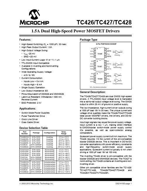
2002-2012 Microchip Technology Inc.
Hale Waihona Puke DS21415D-page 1
TC426/TC427/TC428
Functional Block Diagram
V+
≈500 μA ≈2.5 μA
TC426 TC427 TC428
Noninverting Output (TC427) Input GND NOTE: TC428 has one inverting and one noninverting driver. Ground any unused driver input.
Absolute Maximum Ratings*
Supply Voltage ..................................................... +20V Input Voltage, Any Terminal ................................... VDD + 0.3V to GND – 0.3V Power Dissipation (TA 70°C) PDIP........................................................ 730 mW CERDIP .................................................. 800 mW SOIC ....................................................... 470 mW Derating Factor PDIP....................................................... 8 mW/°C CERDIP .............................................. 6.4 mW/°C SOIC ...................................................... 4 mW/°C Operating Temperature Range C Version ........................................ 0°C to +70°C I Version ....................................... -25°C to +85°C E Version...................................... -40°C to +85°C M Version ................................... -55°C to +125°C Storage Temperature Range.............. -65°C to +150°C
图尔克 TBEN-L5-16DXP 以太网多协议 I O 模块 用户手册说明书
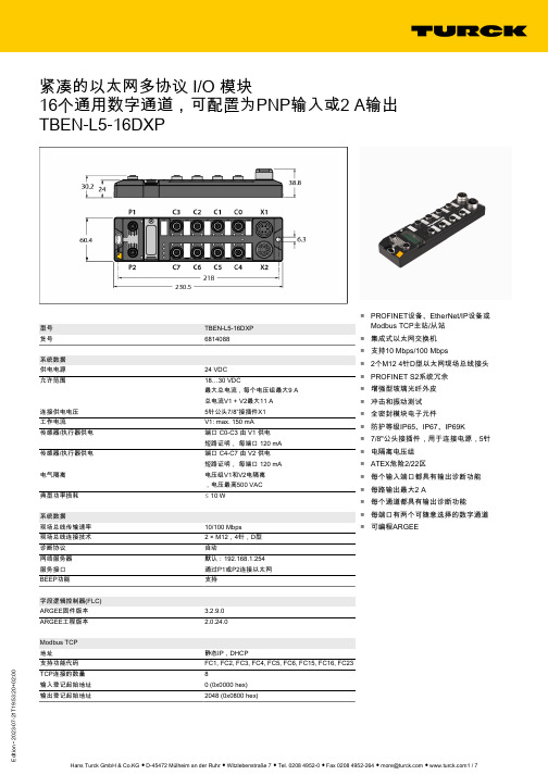
3:20+02:00紧凑的以太网多协议 I/O 模块16个通用数字通道,可配置为PNP输入或2 A输出TBEN-L5-16DXP型号TBEN-L5-16DXP 货号6814088系统数据供电电源24 VDC 允许范围18…30 VDC最大总电流,每个电压组最大9 A 总电流V1 + V2最大11 A连接供电电压5针公头7/8”接插件X1工作电流V1: max. 150 mA 传感器/执行器供电端口 C0-C3 由 V1 供电短路证明, 每端口 120 mA 传感器/执行器供电端口 C4-C7 由 V2 供电短路证明, 每端口 120 mA 电气隔离电压组V1和V2电隔离,电压最高500 VAC 典型功率损耗ð 10 W系统数据现场总线传输速率10/100 Mbps 现场总线连接技术2 × M12,4针,D型诊断协议自动网络服务器默认:192.168.1.254服务接口通过P1或P2连接以太网BEEP功能支持字段逻辑控制器(FLC)ARGEE固件版本 3.2.9.0ARGEE工程版本 2.0.24.0Modbus TCP 地址静态IP,DHCP支持功能代码FC1, FC2, FC3, FC4, FC5, FC6, FC15, FC16, FC23TCP连接的数量8输入登记起始地址0 (0x0000 hex)输出登记起始地址2048 (0x0800 hex)■PROFINET设备、EtherNet/IP设备或Modbus TCP主站/从站■集成式以太网交换机■支持10 Mbps/100 Mbps■2个M12 4针D型以太网现场总线接头■PROFINET S2系统冗余■增强型玻璃光纤外皮■冲击和振动测试■全密封模块电子元件■防护等级IP65、IP67、IP69K ■7/8"公头接插件,用于连接电源,5针■电隔离电压组■ATEX危险2/22区■每个输入端口都具有输出诊断功能■每路输出最大2 A■每个通道都具有输出诊断功能■每端口有两个可随意选择的数字通道■可编程ARGEE3:20+02:00EtherNet/IP 地址符合EtherNet/IP规范快插(QC)< 150 ms 设备级环(DLR)支持3级连接 (TCP)31级连接 (TCP)10输入配置实例101输出配置实例102配置配置实例106PROFINET 版本 2.35地址DCP 一致性分类 B (RT)最小周期时间 1 ms 快速启动(FSU)< 150 ms诊断依据PROFINET报警处理拓扑检测支持自动分配地址支持介质冗余协议(MRP)支持系统冗余S2网络负载等级3数字量输入通道数16Connectivity inputs M12,5针输入类型PNP 输入诊断类型组诊断开关阈值EN 61131-2 分类3, PNP 低电平信号电压< 5 V 高电平信号电压> 11 V 低电平信号电流< 1.5 mA 高电平信号电流> 2 mA 输入延迟 2.5 ms电气隔离与现场总线之间电隔离最高可耐500 VDC的电压数字量输出通道数16Connectivity outputs M12,5针输出类型PNP 诊断通道诊断输出电压24 VDC,来自电势组通道输出电流 2.0 A, 短路保护, 每端口最大 2.0 A 继电器输出 1.3 ms负载类型EN 60947-5-1:DC-13短路保护是电气隔离与现场总线之间电隔离最高可耐500 VDC的电压3:20+02:00标准 / 指令合规性振动测试符合EN 60068-2-6标准加速度最大20 g冲击测试符合 EN 60068-2-27认证滑落和翻倒符合EN 60068-2-31/EN 60068-2-32电磁兼容性符合EN 61131-2标准认证和证书CE,FCC,FM I类,2区,抗紫外线符合DIN EN ISO 4892-2A (2013)标准UL认证cULus LISTED 21 W2, Encl.Type 1 IND.CONT.EQ.有关ATEX/IECEx的注释必须遵守包含有关在爆炸危险2区和22区中使用的信息的快速入门指南。
LTC3415资料

For more information on lead free part marking, go to: /leadfree/ For more information on tape and reel specifications, go to: /tapeandreel/
SYMBOL
PARAMETER
CONDITIONS
MIN TYP MAX UNITS
SVIN
Signal Input Voltage Range
2.375
5.5
V
VFB
Regulated Feedback Voltage
(Note 3)
l 0.590 0.596 0.602
V
ΔVFB
Reference Voltage Line Regulation
Storage Temperature.............................. –65°C to 125°C
PIN CONFIGURATION
TOP VIEW
CLKOUT RUN PVIN PVIN SVIN ITHM ITH
NC 1 SGND 2 PLLLPF 3
LTC4263CS LTC4263CDE 示例电路981A B主板, 单端口自主PSE DAUGHT

LTC4263 in single port Power Over Ethernet (PoE) Power Sourcing Equipment (PSE) Midspan and End-point solutions. The LTC4263 is an autonomous sin-gle-channel PSE controller for use in IEEE802.3af compliant PoE systems. It includes an on-board pla-nar power MOSFET, internal inrush, current limit, and short circuit control, Powered Device (PD) detection and classification circuitry, and selectable AC or DC disconnect sensing. On-board control algorithms provide complete PSE Control operation without the need of a microcontroller. The LTC4263 simplifies ply and a small number of passive support compo-nents. Other options shown on the DC981A include Legacy PD detection enable, Midspan back off timer enable, power class enforce mode, power manage-ment enable. An LED for each port is driven by the respective LTC4263 to indicate the state of the port. Design files for this circuit board are available. Call the LTC factory.LTC is a trademark of Linear Technology CorporationTable 1. Typical DC981 Performance Summary (T A = 25°C)PARAMETER CONDITION VALUE Supply Voltage Voltage for IEEE802.3af Compliance at Port Output 46V to 57V Midspan Mode Detection Backoff Midspan Enabled, Failed Detection 3.2 seconds Detection Range Valid IEEE802.3af PD Detection 17k to 29.7k Set Maximum Allocated Power Power Management Enabled 17WEthernet Powered Pairs Pinout Endpoint PSE, Alternative A (MDI)Midspan PSE, Alternative B1/2(+), 3/6(-)4/5(+) , 7/8 (-)QUICK START PROCEDUREDemonstration circuit 981 is easy to set up to evaluate the performance of the LTC4263. Refer to Figure 2 for proper measurement equipment setup and follow the procedure below.1.Place jumpers in the following positions:ENENDISACACEN 2.Insert daughter card (DC981B) to main board (DC981A) at polarized connector J3.3.Apply 48V across VDD48 and VSS.4.Connect a scope probe at VOUT_MD and VOUT_EP both referenced to positive rail VDD48.5.Connect a valid PD to either Midspan PSE or Endpoint PSE.6.Connect a second PD to the open port.JP1 JP2 JP3 JP4 JP5 JP6Figure 1.Basic DC981A/B Equipment Setupto power the board. This in turn provides power to the Midspan PSE and Endpoint PSE outputs. On each solution, an LTC4263 provides detection of a PD, classification, power management, safe power on of the PD, port current limit, and disconnect detection. Midspan PSE and Midspan ModeIn the Midspan solution, a device (router, switch, etc.) that does not have PoE is connected to MIDSPAN IN. Data is passed through to MIDSPAN OUT along with PoE which goes out to a PD. Power is applied di-rectly to Ethernet pairs 4/5 and 7/8. The LTC4263 circuitry sits in a small layout area behind the RJ45 connector and switches power on the negative rail. To show the different functions of the LTC4263, jumpers allow for the user to select the options of AC or DC disconnect, legacy detection, Midspan backoff timing, and class enforcement. An LED that shows the status of the port is driven by a switcher in the LTC4263 to improve efficiency when VDD5 is pro-vided internally. Push button switch SW1 ties the shutdown pin to ground to disable the LTC4263 in the Midspan solution.A PSE implementing AlternativeB pin out must back off from detection for at least 2 seconds after a failed attempt. This is to avoid conflict of Detection, for ex-ample, should a potential Endpoint PSE and Midspan PSE be connected to the same PD. To enable this feature, set JP2 to DIS. JP2 ties the MIDSPAN pin to VDD5 to enable the LTC4263 backoff timer or to VSS to disable. A 3.2 second delay occurs after every failed detect cycle unless the result is open circuit. If held at VSS, no delay occurs after failed detect cycles. Endpoint PSEThe Endpoint solution is primarily shown on a small daughter card (DC981B). This card is the same height and width as the integrated RJ45 connector that it slides behind on the main board (DC981A). The RJ45 includes Ethernet magnetics and common ter card are VSS, VDD48 and VOUT. Power is switched over from the daughter card out to the Ethernet data pairs (1/2 and 7/8). A PHY can be con-nected to the “TO PHY” to pass data through to the data pairs along with PoE. LED drive and power management pins are also brought out for additional board functions. The board is set up for AC discon-nect, but can be reworked for DC disconnect by re-moving components and replacing with shorts in cer-tain locations. Two solder jumpers also provide se-lectable options for legacy detection and class en-force.Power ManagementThe Midspan and Endpoint PSE, although separate solutions on the DC981, are tied together at the PWRMGT pin for demonstration of the LTC4263 power management capability. Programmable on-board power management circuitry allows multiple LTC4263s to allocate and share power in multi-port systems, allowing maximum utilization of the 48V power supply – all without the intervention of a host processor.The LTC4263 sources current at the PWRMGT pin proportional to the class of the PD that it is powering. The voltage of this pin is checked before powering the port. The port will not turn on if this pin is more than 1V above VSS. The PWRMGT pins of the LTC4263s are tied together and connect to a resistor (RPM) and capacitor (CPM) in parallel to VSS to implement power management among multiple ports. This re-sistor is selected with the following equation:RPM= 213k * W / PFULL_LOADOn the DC981A, the default RPMis 12.4k for a full load power of 17W.19 33 73*RPM= 12.4kTable 3. Powered Device CombinationsPD COMBINATION 1ST PD 2ND PDClass 1 / Class 1 Powered PoweredClass 1 / Class 2 Powered PoweredClass 1 / Class 3** Powered Power Denied Class 2 / Class 2 Powered PoweredClass 2 / Class 3** Powered Power Denied Class 3 **/ Class 3** Powered Power Denied**Class 3 substitutable with Class 0 or 4.If power management is not used, move JP6 to DIS to tie the PWRMGT pins to VSS and disable this fea-ture.Class Enforce ModeENFORCE CLASS jumper JP1 ties the ENFCLS pin of the LTC4263 to either VDD5 or VSS to respectively enable or disable class enforce current limits. If held at VDD5, the LTC4263 will reduce the ICUT threshold for Class 1 or Class 2 PDs. If ENFCLS is held at VSS, ICUT remains at 375mA (typical) for all classes. Table 4. Port Current Limit According to ClassPD CLASS CURRENT THRESHOLD (TYPICAL)Class 1 100mAClass 2 175mAClass 0, 3, 4, or Class En-force Disabled375mALED DriveAn LED pin indicates the state of the port controlled by the LTC4263. When the port is powered, the LED is on; when disconnected or detecting, the LED is off. If an invalid signature is detected or a fault occurs, the LED will flash a pattern that the user or host sys-The logic 5V power supply can be supplied from the internal LTC4263 5V supply or an external 5V supply when above the internal supply. If the internal regula-tor is used, this pin should only be connected to the bypass capacitor and to any logic pins of the LTC4263 that are being held at VDD5.AC and DC DisconnectAC and DC disconnect are two different methods of detecting whether a valid PD is present and requires power. AC disconnect is the default method for the DC981 but can be converted to DC disconnect in the Midspan solution through two jumpers. Moving DISCON (JP4) to DC will short the ACCOUT pin to VSS and configure the LTC4263 to DC disconnect. Moving jumper setting for ACCOMP (JP5) to DC by-passes the AC blocking diode and removes the RC used for AC disconnect from the main circuit. Legacy DetectionLEGACY jumper JP3 controls whether legacy detect is enabled. If the LEGACY pin is held at VDD5 (EN se-lected), legacy detect is enabled and testing for a large capacitor is performed to detect the presence of a legacy PD on the port. If held at VSS (DIS se-lected), only IEEE 802.3af compliant PDs are de-tected. If left floating (no jumper), the LTC4263 enters force-power-on mode and any PD that generates be-tween 1V and 10V when biased with 270µA of detec-tion current will be powered as a legacy device. This mode is useful if the system uses a differential detec-tion scheme to detect legacy devices. Warning: Leg-acy modes are not IEEE 802.3af compliant.Figure 2.DC981 Options。
魏德米勒交换机选型手册

光纤中常用的光波长为1310nm、1550nm,以多模和单 模的方式传播。由于单模光纤在传输中光线没有反射,因此 具有更宽的传输频带和更大的传输容量,能够比多模光纤传 输更远的距离。
应用层 (HTTP,HTTPS,FTP,Telnet,SMTP)
传输层
IP 层
MAC 层 (HDLC,PPP,IEEE802.3/802.2, FDDL,ATM)
物理层 (IEEE802.3,802.5 FDDI,E1A/T1A,232,V.35, V.24)
各种软件,Email, WWW 浏览器等 TCP/UDP
PPP Point to Point Protocol 点到点协议 • 在点对点的链路上封装多协议数据包 • 实现在点到点连接之间的IP 通信 • 能在任何DTE/DCE之间实现通信 • 无速率限制
下图所示以太网TCP/IP模型和构件与开放式系统互连参考模型(OSI模型)对照表。
应用层 表示层 会话层 传输层 网络层 数据链路层 物理层
宽 无风扇外壳散热
工业级标准 小于300ms 20年以上
总之,商用以太网是为舒适的办公室环境而设计的,所 以不适合具有大负载、振动频繁、温度范围宽的工业环境。 由于在生产环境中工业网络必须具备较好的可靠性、可恢复 性和可维护性,而工业以太网设备在设计的时候就考虑到了 工业现场的复杂情况,从而能更加适应工业环境而发挥设备 的作用。
更多新产品敬请关注魏德米勒网站:
A.5
工业以太网的接口
RJ45接口
概述
在以太网中所有数据都被在物理层转化为电信号,用双 绞线传播到另一端后,数据链路层将这些物理层的电气信号 转换为用0、1二进制代码表示的数据帧,这就是交换机接到 的信息。
摩抹PT-7728系列电气61850-324+4G端口层2 гига比特模块管理挂架Ethernet

PT-7728SeriesIEC61850-324+4G-port Layer2Gigabit modular managed rackmount EthernetswitchesFeatures and Benefits•IEC61850-3,IEEE1613(power substations),and EN50121-4(railwayapplications)compliant•IEC62439-3Clause4(PRP)and Clause5(HSR)compliant1•Built-in MMS server based on IEC61850-90-4switch data modeling forpower SCADA•Complies with a portion of EN50155specifications•Turbo Ring and Turbo Chain(recovery time<20ms@250switches),2RSTP/STP,and MSTP for network redundancy•VLAN Unaware:Supports priority-tagged frames to be received by specificIEDs•Up to12ports with M12connectors•Isolated redundant power inputs with universal24VDC,48VDC,or110/220VDC/VAC power supply range•-40to85°C operating temperature rangeCertificationsIntroductionThe PT-7728is designed to meet the demands of power substation automation systems(IEC61850-3,IEEE1613),and railway applications(EN 50121-4),and also features critical packet prioritization(GOOSE and SMVs)and a built-in MMS server.The PT-7728’s Gigabit and Fast Ethernet backbone,redundant ring,and24VDC,48VDC,or110/220VDC/VAC dual isolated redundant power supplies increase the reliability of your communications and save on cabling/wiring costs.The modular design of the PT-7728also makes network planning easy,and allows greater flexibility by letting you install up to4Gigabit ports and24Fast Ethernet ports.Along with the optional front or rear wiring,these features together make the PT-7728suitable for a variety of industrial applications.Additional Features and Benefits•Switch data modeling based on the IEC61850-90-4standard •IEEE1588v2PTP(Precision Time Protocol)for time synchronization of networks(PTP models only)•VLAN Unaware:Supports priority-tagged frames to be received by specific IEDs•DHCP Option82for IP address assignment with different policies •EtherNet/IP and Modbus TCP industrial Ethernet protocols supported•Line-swap fast recovery•Configurable by web browser,Telnet/serial console,CLI,Windows utility,and ABC-01automatic backup configurator •IGMP snooping and GMRP for filtering multicast traffic from industrial Ethernet protocols•Supports advanced VLAN capability with Q-in-Q tagging•IEEE802.3ad,LACP for optimum bandwidth utilization•Bandwidth management to prevent unpredictable network status •Multi-port mirroring for online debugging•Automatic warning by exception through email and relay output •RMON for proactive and efficient network monitoring•Automatic recovery of connected device’s IP addressesCybersecurity Features•User passwords with multiple levels of security protect against unauthorized configuration•SSH/HTTPS is used to encrypt passwords and data•Lock switch ports with802.1X port-based network access control so that only authorized clients can access the port•RADIUS/TACACS+allows you to manage passwords from a central location •802.1Q VLAN allows you to logically partition traffic transmitted between selected switch ports•Secure switch ports so that only specific devices and/or MAC addresses can access the ports•Disable one or more ports to block network traffic•SNMPv3provides encrypted authentication and access security1.Only available with PM-7200-4GTX-PHR-PTP and PM-7200-4GSFP-PHR-PTP modules.2.Gigabit Ethernet recovery time<50msSpecificationsEthernet InterfaceCabling Direction PT-7728-F Series:Front cablingPT-7728-R Series:Rear cablingCompatible Modules Slot1/2/3:PM-7200-8TXPM-7200-2MSC4TXPM-7200-2MST4TXPM-7200-2SSC4TXPM-7200-4MSC2TXPM-7200-4MST2TXPM-7200-4SSC2TXPM-7200-6MSCPM-7200-6MSTPM-7200-6SSCPM-7200-8SFPPM-7200-4M12PM-7200-8MTRJSlot4:PM-7200-4GTXSFPPM-7200-2GTXSFPPM-7200-4GSFP-PHR-PTP(PT-7728-PTP only)PM-7200-4GTX-PHR-PTP(PT-7728-PTP only)Standards IEEE802.1D-2004for Spanning Tree ProtocolIEEE802.1p for Class of ServiceIEEE802.1Q for VLAN TaggingIEEE802.1s for Multiple Spanning Tree ProtocolIEEE802.1w for Rapid Spanning Tree ProtocolIEEE802.1X for authenticationIEEE802.3for10BaseTIEEE802.3ab for1000BaseT(X)IEEE802.3ad for Port Trunk with LACPIEEE802.3u for100BaseT(X)and100BaseFXIEEE802.3x for flow controlIEEE802.3z for1000BaseSX/LX/LHX/ZXEthernet Software FeaturesFilter802.1Q,GMRP,GVRP,IGMP v1/v2c,QinQ VLAN,VLAN unawareIndustrial Protocols EtherNet/IP,Modbus TCPManagement Back Pressure Flow Control,BOOTP,DHCP Option66/67/82,DHCP Server/Client,Flowcontrol,HTTP,IPv4/IPv6,LLDP,Port Mirror,RARP,RMON,SMTP,SNMP Inform,SNMPv1/v2c/v3,Syslog,Telnet,TFTP,Fiber checkMIB Bridge MIB,Ethernet-like MIB,MIB-II,P-BRIDGE MIB,Q-BRIDGE MIB,RMON MIBGroups1,2,3,9,RSTP MIBPower Substation IEC61850QoS,MMSRedundancy Protocols All models:Link Aggregation,MSTP,RSTP,STP,Turbo Chain,Turbo Ring v1/v2PTP models:HSR,PRPSecurity Broadcast storm protection,HTTPS/SSL,TACACS+,Port Lock,RADIUS,Rate Limit,SSHTime Management All models(except PTP models):NTP Server/Client,SNTPPTP models:NTP Server/Client,SNTP,IEEE1588PTP v1/v2(hardware-based)Switch PropertiesIGMP Groups256Max.No.of VLANs64VLAN ID Range VID1to4094Priority Queues4Serial InterfaceConsole Port RS-232(RJ45)Input/Output InterfaceAlarm Contact Channels Resistive load:3A@30VDC,240VACPower ParametersInput Voltage-24-24/-48-48/-HV-HV/-24-HV/-48-HV models:Redundant power modulesPT-7728-24Series:24VDC(18to36VDC)PT-7728-48Series:48VDC(36to72VDC)PT-7728-HV Series:110/220VAC/VDC(85to264VAC,88to300VDC) Overload Current Protection SupportedReverse Polarity Protection SupportedConnection10-pin terminal blockInput Current PT-7728-24Series:2.38A@24VDCPT-7728-48Series:1.12A@48VDCPT-7728-HV Series:0.49/0.26A@110/220VAC,0.59/0.30A@110/220VDC Physical CharacteristicsHousing AluminumIP Rating IP30Dimensions(without ears)440x44x325mm(17.32x1.73x12.80in)Weight5900g(13.11lb)Installation19-inch rack mountingEnvironmental LimitsOperating Temperature-40to85°C(-40to185°F)Note:Cold start requires minimum of100VAC@-40°CStorage Temperature(package included)-40to85°C(-40to185°F)Ambient Relative Humidity5to95%(non-condensing)Standards and CertificationsSafety UL60950-1EMI EN55032Class A,CISPR32,FCC Part15B Class AEMS IEC61000-4-2ESD:Contact:8kV;Air:15kVIEC61000-4-3RS:80MHz to1GHz:35V/mIEC61000-4-4EFT:Power:4kV;Signal:4kVIEC61000-4-5Surge:Power:4kV;Signal:4kVIEC61000-4-6CS:10VIEC61000-4-8PFMFIEC61000-4-11DIPsPower Substation IEC61850-3,IEEE1613Railway EN50121-4,EN50155(complies with a portion of EN50155specifications) Traffic Control NEMA TS2MTBFTime393,828hrsStandards Telcordia SR332WarrantyWarranty Period5yearsDetails See /warrantyPackage ContentsDevice1x PT-7728Series switchCable1x DB9female to RJ4510-pinInstallation Kit4x cap,plastic,for RJ45port2x rack-mounting earDocumentation1x document and software CD1x quick installation guide1x warranty card1x product certificates of quality inspection,Simplified Chinese1x product notice,Simplified ChineseNote SFP modules and/or modules from the PM-7200Module Series need to be purchasedseparately for use with this product.DimensionsOrdering Information12PT-7728-F-2428Up to4Up to24Front–24VDC–-45to85°C PT-7728-R-2428Up to4Up to24Rear–24VDC–-45to85°C PT-7728-F-24-2428Up to4Up to24Front✓24VDC24VDC-45to85°C PT-7728-R-24-2428Up to4Up to24Rear✓24VDC24VDC-45to85°CPT-7728-F-24-HV28Up to4Up to24Front✓24VDC 110/220VDC/VAC-45to85°CPT-7728-R-24-HV28Up to4Up to24Rear✓24VDC 110/220VDC/VAC-45to85°CPT-7728-F-4828Up to4Up to24Front–48VDC–-45to85°C PT-7728-R-4828Up to4Up to24Rear–48VDC–-45to85°C PT-7728-F-48-4828Up to4Up to24Front✓48VDC48VDC-45to85°C PT-7728-R-48-4828Up to4Up to24Rear✓48VDC48VDC-45to85°CPT-7728-F-48-HV28Up to4Up to24Front✓48VDC 110/220VDC/VAC-45to85°CPT-7728-R-48-HV28Up to4Up to24Rear✓48VDC 110/220VDC/VAC-45to85°CPT-7728-F-HV28Up to4Up to24Front–110/220VDC/VAC–-45to85°CPT-7728-R-HV28Up to4Up to24Rear–110/220VDC/VAC–-45to85°CPT-7728-F-HV-HV28Up to4Up to24Front✓110/220VDC/VAC110/220VDC/VAC-45to85°CPT-7728-R-HV-HV28Up to4Up to24Rear✓110/220VDC/VAC110/220VDC/VAC-45to85°CPT-7728-PTP-F-2428Up to4Up to24Front–24VDC–-45to85°C PT-7728-PTP-F-24-2428Up to4Up to24Front✓24VDC24VDC-45to85°CPT-7728-PTP-F-24-HV 28Up to4Up to24Front✓24VDC110/220VDC/VAC-45to85°CPT-7728-PTP-F-4828Up to4Up to24Front–48VDC–-45to85°C PT-7728-PTP-F-48-4828Up to4Up to24Front✓48VDC48VDC-45to85°CPT-7728-PTP-F-HV28Up to4Up to24Front–110/220VDC/VAC–-45to85°CPT-7728-PTP-F-HV-HV 28Up to4Up to24Front✓110/220VDC/VAC110/220VDC/VAC-45to85°CPT-7728-PTP-R-2428Up to4Up to24Rear–24VDC–-45to85°C PT-7728-PTP-R-24-2428Up to4Up to24Rear✓24VDC24VDC-45to85°CPT-7728-PTP-R-24-HV 28Up to4Up to24Rear✓24VDC110/220VDC/VAC-45to85°CPT-7728-PTP-R-4828Up to4Up to24Rear–48VDC–-45to85°CPT-7728-PTP-R-48-4828Up to4Up to24Rear✓48VDC(36-72VDC)48VDC(36-72VDC)-45to85°C12PT-7728-PTP-R-HV 28Up to4Up to24Rear–110/220VDC/VAC–-45to85°CPT-7728-PTP-R-HV-HV 28Up to4Up to24Rear✓110/220VDC/VAC110/220VDC/VAC-45to85°CAccessories(sold separately)PM-7200Module SeriesPM-7200-1BNC2MST-PTP Fast Ethernet module for PT-7728-PTP series with2100BaseFX multi-mode ports with ST connectors,1PPS output with BNC connector,hardware-based IEEE1588PTP V2protocol supportPM-7200-1MSC Fast Ethernet module with1100BaseFX multi-mode port with SC connectorPM-7200-1MST Fast Ethernet module with1100BaseFX multi-mode port with ST connectorPM-7200-2GTXSFP Gigabit Ethernet module with210/100/1000BaseT(X)or1000BaseSFP slot combo portsPM-7200-2MSC Fast Ethernet module with2100BaseFX multi-mode ports with SC connectorsPM-7200-2MSC4TX Fast Ethernet module with2100BaseFX multi-mode ports with SC connectors and410/100BaseT(X)portsPM-7200-2MST Fast Ethernet module with2100BaseFX multi-mode ports with ST connectorsPM-7200-2MST4TX Fast Ethernet module with2100BaseFX multi-mode ports with ST connectors and410/100BaseT(X)portsPM-7200-2SSC Fast Ethernet module with2100BaseFX single-mode ports with SC connectorsPM-7200-2SSC4TX Fast Ethernet module with2100BaseFX single-mode ports with SC connectors and410/100BaseT(X)portsPM-7200-4GTXSFP Gigabit Ethernet module with410/100/1000BaseT(X)or1000BaseSFP slot combo portsPM-7200-4M12Fast Ethernet module with410/100BaseT(X)ports with M12connectorsPM-7200-4MSC2TX Fast Ethernet module with4100BaseFX multi-mode ports with SC connectors and210/100BaseT(X)portsPM-7200-4MST2TX Fast Ethernet module with4100BaseFX multi-mode ports with ST connectors and210/100BaseT(X)portsPM-7200-4SSC2TX Fast Ethernet module with4100BaseFX single-mode ports with SC connectors and210/100BaseT(X)portsPM-7200-6MSC Fast Ethernet module with6100BaseFX multi-mode ports with SC connectorsPM-7200-6MST Fast Ethernet module with6100BaseFX multi-mode ports with ST connectorsPM-7200-6SSC Fast Ethernet module with6100BaseFX single-mode ports with SC connectorsPM-7200-8SFP Fast Ethernet module with8100BaseSFP slotsPM-7200-8TX Fast Ethernet module with810/100BaseT(X)portsPM-7200-8MTRJ Fast Ethernet module with8100BaseFX multi-mode ports with MTRJ connectorsPM-7200-4TX-PTP Fast Ethernet module for PT-7728-PTP series with410/100BaseT(X)ports,hardware-based IEEE1588PTP V2protocol supportPM-7200-4MST-PTP Fast Ethernet module for PT-7728-PTP series with4100BaseFX multi-mode ports with ST connectors,hardware-based IEEE1588PTP V2protocol supportPM-7200-4MSC-PTP Fast Ethernet module for PT-7728-PTP series with4100BaseFX multi-mode ports with SC connectors,hardware-based IEEE1588PTP V2protocol supportPM-7200-4GTX-PHR-PTP Gigabit Ethernet module with41000Base T(X)ports,PRP/HSR protocol supportPM-7200-4GSFP-PHR-PTP Gigabit Ethernet module with4100/1000Base SFP slots,PRP/HSR protocol supportSoftwareMXview-50Industrial network management software with a license for50nodes(by IP address)MXview-100Industrial network management software with a license for100nodes(by IP address)MXview-250Industrial network management software with a license for250nodes(by IP address)MXview-500Industrial network management software with a license for500nodes(by IP address)MXview-1000Industrial network management software with a license for1000nodes(by IP address)MXview-2000Industrial network management software with a license for2000nodes(by IP address)MXview Upgrade-50License expansion of MXview industrial network management software by50nodes(by IP address) Storage KitsABC-01Configuration backup and restoration tool for managed Ethernet switches and AWK Series wirelessAPs/bridges/clients,0to60°C operating temperatureSFP ModulesSFP-1FELLC-T SFP module with1100Base single-mode with LC connector for80km transmission,-40to85°Coperating temperatureSFP-1FEMLC-T SFP module with1100Base multi-mode with LC connector for4km transmission,-40to85°Coperating temperatureSFP-1FESLC-T SFP module with1100Base single-mode with LC connector for40km transmission,-40to85°Coperating temperatureSFP-1G10ALC WDM-type(BiDi)SFP module with11000BaseSFP port with LC connector for10km transmission;TX1310nm,RX1550nm,0to60°C operating temperatureSFP-1G10ALC-T WDM-type(BiDi)SFP module with11000BaseSFP port with LC connector for10km transmission;TX1310nm,RX1550nm,-40to85°C operating temperatureSFP-1G10BLC WDM-type(BiDi)SFP module with11000BaseSFP port with LC connector for10km transmission;TX1550nm,RX1310nm,0to60°C operating temperatureSFP-1G10BLC-T WDM-type(BiDi)SFP module with11000BaseSFP port with LC connector for10km transmission;TX1550nm,RX1310nm,-40to85°C operating temperatureSFP-1G20ALC WDM-type(BiDi)SFP module with11000BaseSFP port with LC connector for20km transmission;TX1310nm,RX1550nm,0to60°C operating temperatureSFP-1G20ALC-T WDM-type(BiDi)SFP module with11000BaseSFP port with LC connector for20km transmission;TX1310nm,RX1550nm,-40to85°C operating temperatureSFP-1G20BLC WDM-type(BiDi)SFP module with11000BaseSFP port with LC connector for20km transmission;TX1550nm,RX1310nm,0to60°C operating temperatureSFP-1G20BLC-T WDM-type(BiDi)SFP module with11000BaseSFP port with LC connector for20km transmission;TX1550nm,RX1310nm,-40to85°C operating temperatureSFP-1G40ALC WDM-type(BiDi)SFP module with11000BaseSFP port with LC connector for40km transmission;TX1310nm,RX1550nm,0to60°C operating temperatureSFP-1G40ALC-T WDM-type(BiDi)SFP module with11000BaseSFP port with LC connector for40km transmission;TX1310nm,RX1550nm,-40to85°C operating temperatureSFP-1G40BLC WDM-type(BiDi)SFP module with11000BaseSFP port with LC connector for40km transmission;TX1550nm,RX1310nm,0to60°C operating temperatureSFP-1G40BLC-T WDM-type(BiDi)SFP module with11000BaseSFP port with LC connector for40km transmission;TX1550nm,RX1310nm,-40to85°C operating temperatureSFP-1GEZXLC SFP module with11000BaseEZX port with LC connector for110km transmission,0to60°C operatingtemperatureSFP-1GEZXLC-120SFP module with11000BaseEZX port with LC connector for120km transmission,0to60°C operatingtemperatureSFP-1GLHLC SFP module with11000BaseLH port with LC connector for30km transmission,0to60°C operatingtemperatureSFP-1GLHLC-T SFP module with11000BaseLH port with LC connector for30km transmission,-40to85°C operatingtemperatureSFP-1GLHXLC SFP module with11000BaseLHX port with LC connector for40km transmission,0to60°C operatingtemperatureSFP-1GLHXLC-T SFP module with11000BaseLHX port with LC connector for40km transmission,-40to85°Coperating temperatureSFP-1GLSXLC SFP module with11000BaseLSX port with LC connector for500m transmission,0to60°C operatingtemperatureSFP-1GLSXLC-T SFP module with11000BaseLSX port with LC connector for500m transmission,-40to85°Coperating temperatureSFP-1GLXLC SFP module with11000BaseLX port with LC connector for10km transmission,0to60°C operatingtemperatureSFP-1GLXLC-T SFP module with11000BaseLX port with LC connector for10km transmission,-40to85°C operatingtemperatureSFP-1GSXLC SFP module with11000BaseSX port with LC connector for300/550m transmission,0to60°Coperating temperatureSFP-1GSXLC-T SFP module with11000BaseSX port with LC connector for300/550m transmission,-40to85°Coperating temperatureSFP-1GZXLC SFP module with11000BaseZX port with LC connector for80km transmission,0to60°C operatingtemperatureSFP-1GZXLC-T SFP module with11000BaseZX port with LC connector for80km transmission,-40to85°C operatingtemperature©Moxa Inc.All rights reserved.Updated Jun18,2019.This document and any portion thereof may not be reproduced or used in any manner whatsoever without the express written permission of Moxa Inc.Product specifications subject to change without notice.Visit our website for the most up-to-date product information.。
专有2.4-GHz的无线音频设计方案

1.引言计的信号范围、音质和最长播放时间方面面临着重大挑战。
为满足这些要求,工程师可以利用来自多家制造商的大量可用产品,包括(按字母顺序)Analog在典型的无线娱乐系统(图1)中,源信号通过带有可选范围扩展器的无线射频接口传输到播放器系统,例如立体声耳机或扬声器。
在播放器内,相应的无线射频接口接收信号以供编解码器、音频处理器或 DSP 处理,以创建驱动到扬声器的最终模拟信号。
一个适当的电源,通常包括一个电池和充电管理电路,完成了系统。
子系统的可用集成解决方案可以帮助工程师满足这些要求,同时降低设计复杂性和成本。
2.频带遗留问题、市场接受度和未授权带宽的可用性通常会推动无线电通信频率的选择。
同时,满足增加操作范围和延长电池寿命的要求为有用频段设置了界限。
对增加功率的需求是对更远距离操作的渴望的自然结果,但射频波长的选择在平衡范围和功率方面起着至关重要的作用。
射频波长和范围之间的关系在Friis 传输方程中进行了描述:其中Pt = 发射功率Pr = 接收功率Gt = 发射器天线增益Gr = 接收器天线增益λ = 波长d = 发射器和接收器之间的距离对于统一参数,距离成为波长的简单线性函数,因此更长波长的无线电通信等同于更大的范围。
当然,更长的波段面临着包括干扰和有效载荷带宽在内的问题。
在这种情况下,2.4 GHz ISM 频段在实际范围限制和有用带宽之间提供了良好的平衡。
2.4 GHz 解决方案的吸引力在于它们能够以低功耗提供有用的有效范围,以及它们的全球可用性。
在蓝牙等标准中使用的基于跳频扩频(FHSS)的2.4 GHz 设计具有在高度活跃的无线电环境中相对不受干扰信号影响的优势。
与较低的ISM 频段相比,这些系统还提供足够的数据带宽,以允许高质量立体声的数字传输,后者通常仅限于模拟或较低数据速率的数字音频。
蓝牙标准工作频率为 2.4 GHz,非常适合消费者的连接要求。
它的广泛使用使得基于蓝牙的无线音频播放器很可能会找到兼容的音频主机,例如计算机、笔记本电脑、平板电脑和智能手机。
LTC2640中文资料

L, LT, LTC and LTM are registered trademarks of Linear Technology Corporation. ThinSOT is a trademark of Linear Technology Corporation. All other trademarks are the property of their respective owners. Protected by U.S. Patents including 5396245, 5859606, 6891433, 6937178 and 7414561.
PIN CONFIGURATION
LTC2640-Z
TOP VIEW
CS/LD 1 SCK 2 SDI 3 GND 4
8 CLR 7 VOUT 6 REF 5 VCC
TS8 PACKAGE 8-LEAD PLASTIC TSOT-23
TJMAX = 150°C (NOTE 6), θJA = 195°C/W
LTC2640
Single 12-/10-/8-Bit SPI VOUT DACs with
10ppm/°C Reference DESCRIPTION
The LTC®2640 is a family of 12-, 10-, and 8-bit voltageoutput DACs with an integrated, high-accuracy, low-drift reference in an 8-lead TSOT-23 package. It has a rail-to-rail output buffer that is guaranteed monotonic.
电压可调的PoE电源适配器[实用新型专利]
![电压可调的PoE电源适配器[实用新型专利]](https://img.taocdn.com/s3/m/f55c5994a26925c52dc5bfc8.png)
专利名称:电压可调的PoE电源适配器专利类型:实用新型专利
发明人:李蒙,任波,武新,李广宏,张灵玲申请号:CN201020123523.2
申请日:20100305
公开号:CN201639476U
公开日:
20101117
专利内容由知识产权出版社提供
摘要:本实用新型公开的电压可调的PoE电源适配器由受电设备控制器芯片LTC4257、集成开关调节器LT3435和提供连接局域网端口芯片ETH1-230LB组成,在所述LTC4257的VIN脚与整流桥D1和D2连接、2脚与电阻R1连接、5脚与8脚连接,在所述LT3435的SW和BOOST间接有电容C9,在Css引脚和输出之间连入电容C10,在所述ETH1-230LB的输入端口RJIN,输出端口RJOUT与以太网ETHERNET的标准接口RJ45端口连接,电信号通过以太网ETHERNET的标准接口RJ45端口输入VSSIN和VSSIN_AT进行两路输入,经桥式整流电路,输入LTC4257进行功率选择以及双电流限制保护,欠压锁定和过载热保护,输出端通过直流/直流转换器DC/DC与LT3435连接的输入端的第三脚VIN连接输出经过配置的电压VOUT12。
可为低功耗的LXI仪器、IP电话机、无线局域网接入点AP、安全网络摄像机等具有网络接口的设备通过网线进行供电。
申请人:洛阳理工学院
地址:471023 河南省洛阳市洛龙区王城大道90号洛阳理工学院计算机与信息工程系
国籍:CN
代理机构:郑州中民专利代理有限公司
代理人:郭中民
更多信息请下载全文后查看。
智能以太网适配器 QL45212 用户指南说明书

第三方信息由 用户指南智能以太网适配器QL45212文档修订历史修订版 A,2015年1月11日修订版 B,2016年4月19日修订版 C,2017年1月27日修订版 D,2017年8月24日修订版 E,2018年1月31日更改受影响的章节第xv页上的“EMI 和 EMC 要求”经更新的EMI/EMC要求:⏹CE标记EMC指令符合性⏹利用EN55032来替换EN55022。
⏹VCCI⏹AS/NZS⏹新增的CNS 13438:2006 A类新增的VCCI语句第xvii页上的“VCCI:A类”第xvii页上的“产品安全符合性”经更新的产品安全符合性:⏹2014年的经更新的UL和UL CSA符合性⏹删除2006/95/EC低电压指令:⏹经更新的TUV EN60950-1和TUV IEC 60950-1第27页上的“VMware 驱动程序和驱动程序包”经更新的表3-5:⏹新增用于显示ESXi驱动程序版本的一列。
⏹新增用于解释针对ESXi6.5而被打包在一起的NIC和RoCE驱动程序的脚注。
向步骤4新增用于指出NPAR在最大速度为1G的第39页上的“使用入门”端口上不可用的注释。
新增用于解释由LLDP数据包使用的源MAC地址第47页上的“配置数据中心桥接”与出厂分配的适配器以太网MAC地址之间的区别的注释。
第53页上的“支持的操作系统和 OFED”更新了表6-1,为 OFED 4.8-1 GA 新增一列。
移除RHEL 7.2、SLES 11 SP4 和 SLES 12 SP2。
新增RHEL 7.4、SLES 12 SP3、CentOS 7.3 和CentOS 7.4更新了步骤2,新增Dynamic(动态)选项。
第55页上的“准备适配器”移除了“RoCE 应用程序和使用”小节并提升了第第69页上的“在 ESX 的适配器上配置 RoCE”72页上的“配置半虚拟 RDMA 设备 (PVRDMA)”第82页上的“在Windows上配置SR-IOV”更新了步骤13,为您的操作系统获取最新的适配器驱动程序,而不是使用内建驱动程序。
LAN-Power LP-2115单口墙装电源过网线(PoE)插座注射器说明说明书

LAN-Power 47835 Westinghouse Drive, Fremont, Ca. 94539 USA Telephone: +1 (510) 275-4572 FAX: +1 (510) 284-2420Web Site Address:Email:*********************LP-2115Single Port Wall Plug Power overEthernet (PoE)Midspan Injector▪Output up to 15.4Watts PoE Power continuously ▪Cost Effective ▪Compliant to 802.3af PoE StandardsFunctions and FeaturesThe LAN Power Model LP-2115SinglePort PoE Midspan Wall Plug Injector supports powering IP ‘PoE Enabled’End Devices.The Single Port PoE Midspan Wall Plug Injector adds up to 15.4wattscontinuously at ~56 VDC to paired wires in a standard Category 5, 5e, or 6 Ethernet cable. The LP-2115delivers both data and power over a single standard Ethernetcable to a PoE enabled End device designed to receive both Data and Power through its RJ45 connector.The second RJ45 passes data only through to Ethernet Switch (up to 100Mbs).The maximum cable distance from Ethernet Switch to end IP Device is 328 feet/100 meters.Key Features of the Single Port PoE Wall Plug Injector include:▪Output Wattage is up to 15.4W continuously▪Compliant to IEEE 802.3af Power over Ethernet Standards ▪Cost Effective▪Data and Power carried on same Ethernet cable▪Supports Data links at 10Mbs or 100Mbs▪Wall Plug design withinterchangeable AC Mains Clips for all countries (sold separately)▪Use with any PoE Compliant device including:o VoIP Phoneso IP Security Cameraso Wireless LAN Access Points o Emerging PoE Products ▪Full 2 Year Product Warranty Safety Approvals▪FCC ▪CE▪UL/cULUnit Dimensions▪Length:3 1/4”(84mm)▪Width:2 1/4”(50mm)▪Height:11/4” (33mm)▪Weight:3.35oz. (95 grams)▪Surge Protection with over voltage current and short circuit protected (protects the Ethernet Switch)▪Extended Temperature operating range▪Multi-Color LED indicator showspowering statusLAN-Power reserves the right to make changes in specifications and other information contained in this document and its web site without prior notice.The reader should consult LAN-Power to determine whether any such changes have been made.©2012 LAN-Power.All rights reserved.Rev.02-12INSTALLATION DIAGRAM802.3af CompliantOrdering InfoModel LP-2115Single Port Wall Plug InjectorEnvironmental SpecificationsOperating Temperature: 32° to 104° F/ 0° to 40° CStorage Temperature:-13° to 149° F/-25°to 65° CRelative Humidity:5% to 90% non-condensingEthernet Data Throughput Speeds10 Mbs Ethernet or 100 Mbs Fast Ethernet supportedConnector TypeNon-Shielded RJ-45meets EIA 568A and 568B Connection Standards Optional Mains Clips for Wall Injector (ordered separately)Part NumberCountryLP-MCUK United Kingdom LP-MCEUR Europe LP-MCI India LP-MCCChinaElectrical Specifications and Properties AC Power InputVoltage Range:90-264VAC Voltage Rating:100-240VAC Frequency Range:47-63HzInput Current:0.8A (rms) maximum for 90VAC0.5A (rms) maximum for 240VACLeakage Current: 0.25mA maximum @254VAC 60HzDC Power OutputPoE Protocol:IEEE 802.3afPower on Data Pins:4 & 5 (+), 7 & 8 (-)Output Voltage:56VDCMax. Power on Port: 15.4W (IEEE 802.3af PoE Standard)Load:0A (Min.) 0.275A (Max.)Regulation (Line/Load):± 4%Ripple and Regulation: 100mV maximum Efficiency:75%typical at maximum load and 120VAC, 60HzHold-up Time:16mS minimum at maximum load and 120VAC, 60HzTransient O/P Voltage Protection: 60V maximum at switch on/off at any AC line phaseOver Voltage/Current, Short Circuit ProtectionThe output is equipped with short circuit protection and overload protection as per IEEE802.3af specifications and conforms to UL60950-2. The output can be shorted permanently without damage.LED Indicators:SOLID GREEN –Valid IP PoEEnabled Device Connected and PoE Power going to deviceBLINKING GREEN /RED –Invalid IP End Device/Load ConnectedSOLID RED –Fault Detected (short,overload, etc)。
4端口以太网供电(POE)控制器

4端口以太网供电(POE)控制器
佚名
【期刊名称】《今日电子》
【年(卷),期】2009(0)7
【摘要】LTC4266在4线对以太网电缆系统上提供高达100W的功率,并与新
的IEEE802.3atPoE+标准完全兼容,以及与之前的IEEE802.3afPoE标准兼容。
性能特点:4个独立的PSE通道;在600mA时提供每端口130mW;先进的电源管理,包括了8位可编程电流限制(ILIM),7位可编程过载电流限制(ICUT),预选端口的快速停机,14.5位端口电流/电压监视,两事件分级;具非常高可
靠性的4点PD检测;
【总页数】1页(P67-67)
【关键词】以太网供电;端口;IEEE802;控制器;电流限制;电缆系统;性能特点;电源管
理
【正文语种】中文
【中图分类】TN86;TP393.08
【相关文献】
1.LTC4265:以太网供电(PoE)接口控制器 [J],
2.三泰管理型以太网络交换器ESW with PoE系列首创透过以太网络端口直接供电[J],
3.自主式单端口以太网供电控制器 [J],
4.红狮针对工业需求推出更多增强型千兆以太网供电(PoE+)产品——新型
POE+交换机和供电器为客户提供了更多端口、计数和功能选择 [J],
5.单端口以太网供电(PoE)控制器 [J],
因版权原因,仅展示原文概要,查看原文内容请购买。
LTC4266A/4274A:供电控制器

LTC4266A/4274A:供电控制器
佚名
【期刊名称】《世界电子元器件》
【年(卷),期】2011(000)009
【摘要】凌力尔特公司推出面向供电设备(PSE)的4端1:3和单端VI以太网
供电(PoE)控制器LTC4266A和LTC4274A,可向受电设备(PD)提供90W
的功率,实现了高功率PoE应用,包括长距离无线接入点(WAP)、瘦客户机等。
【总页数】1页(P35-35)
【正文语种】中文
【中图分类】TN86
【相关文献】
1.AT供电系统同相供电PR控制器设计 [J], 马庆安;李群湛;解绍锋;徐英雷
2.基于双星型多电平潮流控制器与YNvd变压器的同相供电系统 [J], 周净轩;罗隆福;王海龙
3.中压配电网双电源供电智能控制器的研究 [J], 赵亮
4.供电网络对CRH5型动车组内外端门控制器的影响分析 [J], 黄常维
5.Silicon Laboratories推出高集成度以太网络供电控制器——Si3400代表公司
正式进入成长中的以太网络供电市场 [J],
因版权原因,仅展示原文概要,查看原文内容请购买。
ARK-5280

无风扇,可扩展 PC 板的嵌入式工控机
● 紧凑,密封结构无风扇运行,支持 I n t e l P e n t i u m M 和 Celeron M 最高到 1.8 GHz ●通过内置系统数字DVI和模拟VGA/CRT接口支持双独立显示 ●支持4个串口和4个USB接口 ● 内置一个PCI扩展槽,以及一个PCI/ISA(共享)扩展槽 ●用于 PC 扩展板防震动设计的橡胶固定条 ● 确保硬盘最大可靠性的防振设计 ● 支持直流输入(DC 9V-32V)ATX 电源模块 ● 可快速安装、扩展和易于维护的简单、模块化设计
com2的默认设置为rs232com2的rs422485模式可以通过更换内部电缆和调整系统内跳线来支持3xrs232com端口用作com1com3com41xps2用作ps2键盘鼠标接口线入线出和麦克风入接口speakout装箱单1xark5280主机17000602021xps2键盘鼠标电缆20665280011x工具cd19600044531x后端安装托架2x底部安装托架1960004454注意2个底部安装托架中的1个可以用于台式安装或壁挂式安装17000018611x电源线din插孔到dc插孔17000021921x扁平电缆支持rs485rs422模式用于com2串口17000017941xide扁平电缆44p20mmto40p254mm23cm型号附件名称ark52801s5a2eceleronm15ghz嵌入式工控机带vgadvi高速以太网2xusb4xcomac97音频1个pci扩展槽和一个pciisa共享扩展槽512mbddrsdramark52801s8a2epentiumm18ghz嵌入式工控机带vgadvi高速以太网2xusb4xcomac97音频1个pci扩展槽和一个pciisa共享扩展槽512mbddrsdram订货信息型号附件名称外部actodc适配器和电源电缆1757000537120wactodc适配器4pdc19v632a96cbpowerb18m电源线3p150厘米用于中国9689071001电源线3p180厘米用于美国170203183c电源线3p183厘米用于欧洲1700001934用于ark5280的双usb电缆安装片1700002224用于ark5280的lvdsusb扩展的安装片1700002223用于ark5280的打印接口扩展的安装片可选项目ark5280安规认证ark5280无风扇强大运算性能使用低功耗处理器密封结构无风扇工作支持socket479型嵌入式intelpentiumm和celeronm处理器可达18ghz紧凑尺寸坚固结构坚固密封的铸铝结构提供最大空间效能用于pci扩展板的橡胶防振板卡固定条确保最大可靠性的硬盘抗振托高度优化整合简单模块化设计快速安装易于扩展和易于维护系统即拿即用支持宽范围dc9v32v电源插入支持atx灵活用于各种自动化环境中应用更长的产品寿命周期支持提供可靠的投资收益应用优势
