FWC-2.2
大华电器 fan coil 用户手册说明书

USER MANUAL FWC06B7TV1BFWC07B7TV1BFWC08B7TV1BFWC09B7TV1BFWC06B7FV1BFWC07B7FV1BFWC08B7FV1BFWC09B7FV1BUser manual 1FWC Fan coil units 4PW65029-1A – 05.2011IntroductionTable of contents1IntroductionThank you for purchasing this DAIKIN fan coil unit.1.1.About fan coil units A fan coil unit provides heating and/or cooling to individual spaces. It creates a comfortable environment in both commercial and residential applications. Fan coil units are widely used for the air conditioning of offices, hotels and houses.The main components of fan coil units are:■ a fan,■ a heat exchanger.The heat exchanger receives hot or cold water from a heating or cooling source.DAIKIN offers a wide range of fan coil units for both concealed and exposed applications. Contact your installer for a list of related products.1.2.About your fan coil unitYou have purchased the FWC model fan coil unit. The model identification code means:The following models are available:■FWC06-07-08-09B7T V1B 2-pipe fan coil units have a single-circuit heat exchanger. The device can be used for either cooling or heating.■FWC06-07-08-09B7F V1B4-pipe fan coil units have a double-circuit heat exchanger. The units can be connected to both cooling and heating systems. Use this type if you have a separate source for cooling and forheating.1.3.About this document This document is a user manual. It is written for the person who owns or operates this fan coil unit. It provides information on: ■the product itself (“Introduction” on page 1),■what you should do before you operating the fan coil unit (“Before operating” on page 2),■what you should do for optimal operation of your fan coil unit (“Tips for optimal operation” on page 3),■how you should clean your fan coil unit (“Clean your fan coil unit” on page 4),■what you should do when there is a problem with your fan coil unit (“Solve problems with your fan coil unit” on page 4),■how you should dispose of your fan coil unit (“Dispose of your fan coil unit” on page 4),■terms that have been used in this user manual that may need clarification (“Glossary” on page 4).Keep this user manual close to hand. It may come in handy later.The original documentation is written in English. All other languages are translations of the original documentation.1Introduction11.1.About fan coil units11.2.About your fan coil unit11.3.About this document11.3.1.Meaning of warnings andsymbols 22Before operating22.1.Check that you have all equipment andthe corresponding documentation22.2.Read the safety precautions 33Tips for optimal operation 34Clean your fan coil unit 45Solve problems with your fan coil unit 46Dispose of your fan coil unit 47Glossary4Annex: Handover of the installation tothe user 5067FW Water fan coil unit C Subclass: Cassette C: 3x306Total cooling capacity (kW)B Major model change 7Minor model change T Coil type: T: 2-pipe F: 4-pipe V1 1 phase / 50 Hz / 220-240 V B Produced in Europe ImportantThis user manual does not explain how to operate your fan coil unit. You can only operate your fan coil unit by means of a controller. Therefore, the operating instructions areincluded in the controller box.FWCFan coil units4PW65029-1A – 05.2011User manual 2Before operating1.3.1.Meaning of warnings and symbolsWarnings in this manual are classified according to their severity and probability of happening.Some types of danger are represented by special symbols:Other symbols:2Before operating2.1.Check that you have all equipment and the corresponding documentation Extra required equipmentThe fan coil unit must be used in combination with additional equipment.This equipment must be bought separately and is required to operate the fan coil unit safely and comfortably.Overview of additional equipment required:■decoration panel,■controller.An overview of the types that are available:Mandatory equipment: Each fan coil unit must be connected to at least one of the listed controllers.Information : This symbol identifies useful information, but no hazardous situation warnings.This part of the manual is intended for the installer of thisproduct.Decoration panel - standard BYCQ140CW1Decoration panel for the fan coil unit with normal sealingcolour.Decoration panel - white BYCQ140CW1W Decoration panel for the fan coil unit with white sealings.Controllers Identification code DescriptionElectronic remote controller - wireless(cooling and heating)BRC7F532F Wireless remote controller to control each fan coil unit independently with cooling and heating functionality.Remark:■Refer to the VRV system in the operationmanual.■The function“auto fan speed”is not available.Electronic remotecontroller - wireless(cooling only)BRC7F533FWireless remote controller to control each fan coil unit independently with cooling functionality only.Remark: ■Refer to the VRVsystem in theoperationmanual.■The function“auto fan speed”is not available.Electronic remote controller - wired BRC315D7Wired remote controller to control each fan coil unit independently with cooling and heating functionality.Central remote controller DCS302CA51Remote controller for centralized control of all connected units.Intelligent touch controller DCS601C51C Advanced remote controller for centralized control of all connected units.Unified ON/OFFcontroller DCS301BA51Remote controller to switch all connectedunits ON or OFF.User manual 3FWC Fan coil units 4PW65029-1A – 05.2011Before operatingExtra optional equipmentOptionally, you can buy additional equipment for your fan coil unit to extend the life of your product, increase the level of automation and improve its ease of use.Overview of the optional additional equipment for your fan coil unit:An overview of the types that are available:■air handling options,■sensor,■timer,■valves,■electronic circuits (PCB). 2.2.Read the safety precautions Your fan coil unit is built to meet all recognized technical requirements. Operate your fan coil unit according to the instructions in the included documentation and the manuals of the additional equipment (e.g. controller). Any other usage is considered as improper and may result in property damage, serious physical injuries or death. Resulting damage caused by improper use is the sole responsibility of the user and the user alone.To prevent any risk: ■ carefully read the safety precautions,■ operate your fan coil unit according to the documentation.Precautions for installationThe installer should install and connect your fan coil unit as described in the installation manual. Please note that the installer can only install your fan coil unit:■in a concealed ceiling,■in perfect condition.Precautions before operatingOnly operate your fan coil unit after it has been installed by a licensed installer. Verify that the installation has been completed by checking that the “Annex: Handover of the installation to the user” on page 5 has been filled in completely. Precautions for operatingOnly operate a fan coil unit if you are fully alert and aware. Fan coil units are not intended for use by persons with reduced physical, sensory or mental capabilities or those who have not used the fan coil unit before, including children. When these persons want to use the fan coil unit, the person responsible for their safety must supervise them or instruct them in the use of the fan coil unit.Supervise children to ensure that they do not play with the fan coil unit.If you feel unsure about operating the fan coil unit, contact your installer for advice and information.3Tips for optimal operation ■Adjust the room temperature properly for a comfortableenvironment. Avoid excessive heating or cooling. Notice that it may take some time for the room temperature to reach the set temperature. Consider using the timer setting options.■Prevent direct sunlight from entering a room during cooling operation by using curtains or blinds.■Ventilate the room regularly. Using the unit for long periods of time requires attentive ventilation of the room.■Keep doors and windows closed when the unit is in operation. If the doors and windows remain open, air will flow out anddecrease the effect of cooling and heating.■Never place objects near the air inlet and the air outlet of the unit. It may reduce the effectiveness or cause the unit to stop.■Turn off the main power supply switch when not using the fan coil unit for long periods of time. Electricity is consumed so long as the switch is on. Turn off the main power supply switch in order to save energy.■Fully use the function of air flow direction adjustment if available. As cold air gathers on the floor and warm air gathers against the ceiling, it is recommended to set the air flow direction during cooling operation parallel to the ceiling and to set it downwards during heating operation. Be sure that you do not direct air flow on to the inhabitants of the room.Sealing member of air discharge outlet KDBHQ55C140Blocking parts to close one or more air outlets of the fan coil unit.Long-lifereplacement filter KAFP551K160High quality filter.Fresh air intake kit KDDQ55C140Kit which can be connected to the ventilation system inorder to supply freshair to the fan coil unit.Remote temperature sensor KRCS01-4Replacement sensor to measure temperature remotely from a location other than that in which the controller is installed.Schedule timer DST301BA51Controller with schedule timing functionality.2-way valve (ON/OFF type)EKMV2C09B7Electronic 2-way valve to control the water supply (+EKRP1C11).3-way valve (ON/OFF type)EKMV3C09B7Electronic 3-way valve to control the water supply (+EKRP1C11).Valve control PCB EKRP1C11Mandatory electronic circuit when 2-way or 3-way valve is used.Optional PCB for Modbus connection EKFCMBCB7Electronic circuit with Modbus interfaceconnections.Wiring adaptor for electrical appendices KRP4A(A)53KRP2A52Electronic circuit with additionalconnections forexternal input/outputsignals.FWCFan coil units4PW65029-1A – 05.2011User manual4 Clean your fan coil unit4Clean your fan coil unitTo clean the outside of your fan coil unit:1Switch off the fan coil unit.2Clean the outside of the fan coil unit with a soft cloth.Never clean your fan coil unit with:■any aggressive chemical solvent,■water hotter than 50°C.For maintenance of your fan coil unit, contact your installer or service company.5Solve problems with your fan coil unitWhen your fan coil unit does not function well, you can try to solve any problem with the corrective actions in this chapter.If the problem persists or is not addressed in this chapter, contact your installer or service company.Your fan coil unit does not functionIf your fan coil unit does not function:Your fan coil unit does not cool or heat wellIf your fan coil unit does not cool or heat well:Your fan coil unit leaks waterShut down the unit and contact your installer or service company.6Dispose of your fan coil unitYour fan coil unit was designed to be environment friendly. DAIKIN has complied with the standards for environmentally-friendly disposal. This means that you have to dispose of your fan coil unit in accordance with the applicable legislation. By ensuring this product is disposed of correctly, you help to prevent potential negative consequences for the environment and human health.Fig. 6.1: WEEE symbolYour fan coil unit is categorized as an electrical and electronic product. It is marked with the symbol illustrated in figure “WEEE symbol” on page 4. This symbol means that your fan coil unit should be recycled and not disposed of in unsorted municipal waste.To dispose of your fan coil unit, contact your installer. The installer and qualified instances will:■dismantle the fan coil unit,■re-use, recycle and recover parts of the fan coil unit.DAIKIN and the environment thank you!7GlossaryCheck:If yes,Has the fan coil unit beenswitched OFF?Switch the fan coil unit ON. Is there a power failure?Restore the power supply.Has the circuit breaker (fuse) been tripped?Contact your installer or service company.Check:If yes,Is there an obstacle near the airinlet or air outlet?Remove the obstacle.Are any doors and windowsopen?Close doors and windows.Is the fan coil unit running at low speed?Select medium speed or highspeed.Are the air filters dirty?Contact your installer or servicecompany.Term MeaningApplicablelegislation:All international, European, national and localdirectives, laws, regulations and/or codes whichare relevant and applicable for a certain product ordomainCircuitbreaker (fuse):Safety device used in electrical installations toprevent electric shockInstaller:Technical skilled person who is qualified to installfan coil units and other DAIKIN productsServicecompany:Qualified company which can perform orcoordinate the required service to the fan coil unitUser manual 5FWC Fan coil units 4PW65029-1A – 05.2011Annex: Handover of the installation to the user Annex: Handover of the installation to theuserTo be filled in by the installer once the test run is finished and the fan coil unit(s) operate(s) properly.Date:Signature:Fan coil unit 1Fan coil unit 2Place ofinstallation:Place of installation:Model name:Model name:Optional equipment:Optional equipment:Fan coil unit 3Fan coil unit 4Place ofinstallation:Place of installation:Model name:Model name:Optional equipment:Optional equipment:Fan coil unit 5Fan coil unit 6Place ofinstallation:Place of installation:Model name:Model name:Optional equipment:Optional equipment:Fan coil unit 7Fan coil unit 8Place ofinstallation:Place of installation:Model name:Model name:Optional equipment:Optional equipment:Your DAIKIN product was installed by:Co p yri g h t2010Da i k in 4PW65029-1A 05.2011。
钢板筒仓设计规范

中华人民共和国国家标准粮食钢板筒仓设计规范Code for design of grain steel silosGB 50322-2001主编部门:国家粮食局批准部门:中华人民共和国建设部施行日期:2001年7月1日关于发布国家标准《粮食钢板筒仓设计规范》的通知根据我部“关于印发《2000至2001年度工程建设国家标准制订、修订计划》的通知”(建标[2001]87号)的要求,由国家粮食局会同有关部门共同修订的《粮食钢板筒仓设计规范》,经有关部门会审,批准为国家标准,编号为GB 50322-2001,自2001年7月1日起施行。
其中,3.1.6、4.1.4、4.2.1、4.3.2、4.4.2、5.1.2、5.2.2、5.5.3、6.4.2、7.3.1、8.1.2、8.6.1 为强制性条文,必须执行。
原行业标准《粮食钢板筒仓设计规范》同时废止。
本规范由国家粮食局负责管理,郑州粮食食品工程建筑设计院负责具体解释工作,建设部标准定额研究所组织中国计划出版社出版发行。
中华人民共和国建设部二○○一年六月十三日前言本规范根据国家建设部建标[2001]87号文编制。
本规范分8章和5个附录,包括:总则、术语、一般规定、荷载及荷载效应组合、结构设计、构造、工艺设计、电气及配套设施等内容。
本规范中强制性条款在正文中用黑体字表示,包括:3.1.6、4.1.4、4.2.1、4.3.2、4.4.2、5.1.2、5.2.2、5.5.3、6.4.2、7.3.1、8.1.2、8.6.1。
本规范系首次编制,有些条款还待进一步补充、完善。
请各单位在执行过程中,结合工程实践与科学研究,认真总结经验,注意积累资料,并将有关意见和资料寄交编制组。
本规范由郑州粮油食品工程建筑设计院负责具体解释,通信地址:郑州市嵩山南路140号,邮编:450052。
本规范主编单位、参编单位和主要起草人:主编单位:郑州粮油食品工程建筑设计院参编单位:原国家粮食储备局北京科学研究设计院原国家粮食储备局郑州科学研究设计院中谷粮油集团北京煤炭设计研究院长沙冶金设计研究院北京粮油集团主要起草人:袁海龙杨世忠朱同顺李建萍郭呈周崔元瑞归衡石王刚郝卫洪宋春燕兰勇吴强李江华杜月萍王守德张振镕1 总则1.0.1 为在粮食钢板筒仓设计中贯彻执行国家技术经济政策,做到安全适用、技术先进、经济合理,制定本规范。
GB50322钢筒仓设计规范

华润酒精 工程部质量管理处标准汇总中华人民共和国国家标准粮食钢板筒仓设计规范Code for design of grain steel silosGB 50322-2001主编部门:国家粮食局批准部门:中华人民共和国建设部施行日期:2001年7月1日关于发布国家标准《粮食钢板筒仓设计规范》的通知根据我部“关于印发《2000至2001年度工程建设国家标准制订、修订计划》的通知”(建标[2001]87号)的要求,由国家粮食局会同有关部门共同修订的《粮食钢板筒仓设计规范》,经有关部门会审,批准为国家标准,编号为GB 50322-2001,自2001年7月1日起施行。
其中,3.1.6、4.1.4、4.2.1、4.3.2、4.4.2、5.1.2、5.2.2、5.5.3、6.4.2、7.3.1、8.1.2、8.6.1 为强制性条文,必须执行。
原行业标准《粮食钢板筒仓设计规范》同时废止。
本规范由国家粮食局负责管理,郑州粮食食品工程建筑设计院负责具体解释工作,建设部标准定额研究所组织中国计划出版社出版发行。
中华人民共和国建设部二○○一年六月十三日前 言本规范根据国家建设部建标[2001]87号文编制。
本规范分8章和5个附录,包括:总则、术语、一般规定、荷载及荷载效应组合、结构设计、构造、工艺设计、电气及配套设施等内容。
本规范中强制性条款在正文中用黑体字表示,包括:3.1.6、4.1.4、4.2.1、4.3.2、4.4.2、5.1.2、5.2.2、5.5.3、6.4.2、7.3.1、8.1.2、8.6.1。
本规范系首次编制,有些条款还待进一步补充、完善。
请各单位在执行过程中,结合工程实践与科学研究,认真总结经验,注意积累资料,并将有关意见和资料寄交编制组。
本规范由郑州粮油食品工程建筑设计院负责具体解释,通信地址:郑州市嵩山南路140号,邮编:450052。
本规范主编单位、参编单位和主要起草人:主编单位:郑州粮油食品工程建筑设计院参编单位:原国家粮食储备局北京科学研究设计院原国家粮食储备局郑州科学研究设计院中谷粮油集团北京煤炭设计研究院长沙冶金设计研究院北京粮油集团主要起草人:袁海龙 杨世忠 朱同顺 李建萍 郭呈周 崔元瑞 归衡石 王 刚 郝卫洪 宋春燕 兰 勇 吴强 李江华 杜月萍 王守德 张振镕1 总则华润酒精 工程部质量管理处标准汇总1 总则1.0.1 为在粮食钢板筒仓设计中贯彻执行国家技术经济政策,做到安全适用、技术先进、经济合理,制定本规范。
某地市两层小别墅电气施工图
特灵FCU

制热量 额定输入功率
排水管
FWC04
供水进口 供水出口 电源线 B 30
D
850
水流量 水阻力
C 天花板孔(870-890) 809
22
A
950
598
外形尺寸 mm
320 288 388 348
830x235x830 850x263x850 850x298x850 850x298x850 850x298x850
液晶型温度控制器
产品概述 产品功能
供回水管 排水管 830 60
机组四面广角环绕送风,送风均匀,气流分布合理,在家中或办公室内营造出舒适宜人的 环境。
超薄设计
嵌入天花式的设计,集豪华与典雅于一体,极富装饰性。室内机高度低,节省更多的室内 有效空间。
控制灵活方便
机组采用无线遥控,可进行制冷,制热,通风或自动运转等工况的转换,也可进行定时的 设定。
WxHxD 出风口尺寸
373 950
mm WxH 冷冻水接头 排水管接头 排水泵杨程 控制方式 mm mm
348 196 240 216
300x60(四个) 3/4”内螺纹 16.5 700 遥控
FWC06/08/10/12
型号 天花板最小高度mm(A) 支架高度mm(B) 排水高度mm(C) 供水管位置mm(D) FWC04 FWC06 FWC08/10/12 290 180 230 250 313 161 240 216
FWD10 1370
188 1640 1370
820
0~245
6.54
0.31
16
12.12
3
2.8/3.6
10.4 16.21 0.38 1.8 4.5 45 41 37 1130 715 315
梅特勒(常州)托利多称重传感器参考资料
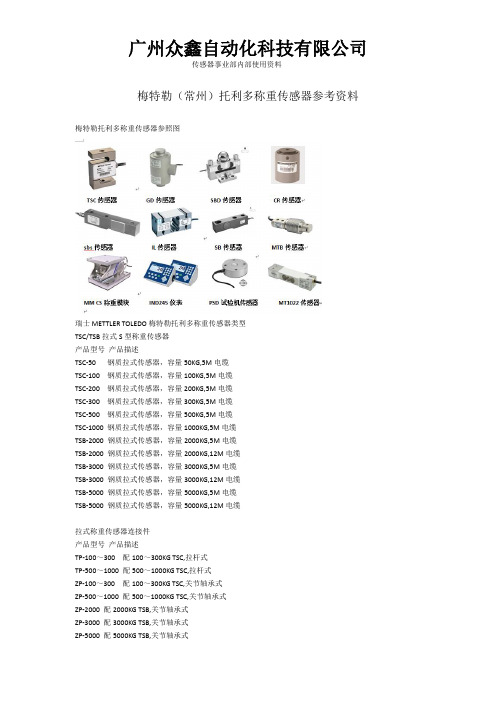
梅特勒(常州)托利多称重传感器参考资料梅特勒托利多称重传感器参照图瑞士METTLER TOLEDO梅特勒托利多称重传感器类型TSC/TSB拉式S型称重传感器产品型号产品描述TSC-50 钢质拉式传感器,容量50KG,5M电缆TSC-100 钢质拉式传感器,容量100KG,5M电缆TSC-200 钢质拉式传感器,容量200KG,5M电缆TSC-300 钢质拉式传感器,容量300KG,5M电缆TSC-500 钢质拉式传感器,容量500KG,5M电缆TSC-1000 钢质拉式传感器,容量1000KG,5M电缆TSB-2000 钢质拉式传感器,容量2000KG,5M电缆TSB-2000 钢质拉式传感器,容量2000KG,12M电缆TSB-3000 钢质拉式传感器,容量3000KG,5M电缆TSB-3000 钢质拉式传感器,容量3000KG,12M电缆TSB-5000 钢质拉式传感器,容量5000KG,5M电缆TSB-5000 钢质拉式传感器,容量5000KG,12M电缆拉式称重传感器连接件产品型号产品描述TP-100~300 配100~300KG TSC,拉杆式TP-500~1000 配500~1000KG TSC,拉杆式ZP-100~300 配100~300KG TSC,关节轴承式ZP-500~1000 配500~1000KG TSC,关节轴承式ZP-2000 配2000KG TSB,关节轴承式ZP-3000 配3000KG TSB,关节轴承式ZP-5000 配5000KG TSB,关节轴承式SB系列剪切梁传感器产品型号产品描述SB-0.3 剪切梁传感器,容量0.3T,盲孔,4M电缆SB-0.5t 剪切梁传感器,容量0.5T,盲孔,4M电缆SB-0.5t 剪切梁传感器,容量0.5T,盲孔,12M电缆SB-1t 剪切梁传感器,容量1T,盲孔,4M电缆SB-1t 剪切梁传感器,容量1T,盲孔,12M电缆SB-2t 剪切梁传感器,容量2T,盲孔,4M电缆SB-2t 剪切梁传感器,容量2T,盲孔,12M电缆SB-3t 剪切梁传感器,容量3T,盲孔,4M电缆SB-5t 剪切梁传感器,容量5T,盲孔孔,5M电缆SB-10t 剪切梁传感器,容量10T,盲孔孔,6M电缆SB-15t 剪切梁传感器,容量15T,盲孔孔,10M电缆SB-20t 剪切梁传感器,容量20T,盲孔孔,10M电缆SBT系列剪切梁传感器产品型号产品描述SBT-0.3t 剪切梁传感器,容量0.3T,通孔,4M电缆SBT-0.5t 剪切梁传感器,容量0.5T,通孔,4M电缆SBT-1t 剪切梁传感器,容量1T,通孔,4M电缆SBT-2t 剪切梁传感器,容量2T,通孔,4M电缆SBT-3t 剪切梁传感器,容量3T,通孔,4M电缆SBT-5t 剪切梁传感器,容量5T,通孔,5M电缆SBS系列剪切梁传感器产品型号产品描述SBS-0.3t 剪切梁传感器,容量0.3T,螺纹孔,4M电缆SBS-0.5t 剪切梁传感器,容量0.5T,螺纹孔,4M电缆SBS-1t 剪切梁传感器,容量1T,螺纹孔,4M电缆SBS-2t 剪切梁传感器,容量2T,螺纹孔,4M电缆SBS-3t 剪切梁传感器,容量3T,螺纹孔,4M电缆SBC系列紧密型剪切梁称重传感器及其连接件产品型号产品描述SBC-0.5t 紧密型剪切梁传感器,容量0.5T,3M电缆SBC-0.5t 紧密型剪切梁传感器,容量0.5T,6M电缆SBC-1t 紧密型剪切梁传感器,容量1T,3M电缆SBC-1t 紧密型剪切梁传感器,容量1T,6M电缆SBC-2t 紧密型剪切梁传感器,容量2T,3M电缆SBC-2t 紧密型剪切梁传感器,容量2T,6M电缆SBC-3t 紧密型剪切梁传感器,容量3T,3M电缆SBC-3t 紧密型剪切梁传感器,容量3T,6M电缆连接件SPC-0.5~3T 紧密型剪切梁称重传感器专用连接件SPC-5T 紧密型剪切梁称重传感器专用连接件SBH系列不锈钢焊接密封传感器产品型号产品描述SBH-0.25t 弯曲梁称重传感器,称重容量0.25T,5M电缆SBH-0.5t 弯曲梁称重传感器,称重容量0.5T,5M电缆SBH-1t 弯曲梁称重传感器,称重容量1T,5M电缆SBH-2t 弯曲梁称重传感器,称重容量2T,5M电缆SBH-3t 弯曲梁称重传感器,称重容量3T,5M电缆SBH-5 弯曲梁称重传感器,称重容量5T,5M电缆IL系列称重传感器产品型号产品描述IL-150KG 钢质弯曲梁传感器,容量150KG,2.5M电缆IL-250KG 钢质弯曲梁传感器,容量250KG,2.5M电缆IL-500KG 钢质弯曲梁传感器,容量500KG,2.5M电缆IL-1000KG 钢质弯曲梁传感器,容量1000KG,2.5M电缆IL-2000KG 钢质弯曲梁传感器,容量2000KG,2.5M电缆0745A/0743系列不锈钢焊接密封传感器产品型号产品描述0745A-0.22t 0745A称重传感器0.22T,2.2M电缆0745A-0.22t 0745A称重传感器0.22T,4.5M电缆0745A-0.22t 0745A称重传感器0.22T,9M电缆0745A-0.55t 0745A称重传感器0.55T,2.2M电缆0745A-0.55t 0745A称重传感器0.55T,4.5M电缆0745A-0.55t 0745A称重传感器0.55T,9M电缆0745A-1.1t 0745A称重传感器1.1T,2.2M电缆0745A-1.1t 0745A称重传感器1.1T,4.5M电缆0745A-1.1t 0745A称重传感器1.1T,9M电缆0745A-2.2t 0745A称重传感器2.2T,2.2M电缆0745A-2.2t 0745A称重传感器2.2T,4.5M电缆0745A-2.2t 0745A称重传感器2.2T,9M电缆0745A-4.4t 0745A称重传感器4.4T,4.5M电缆0745A-4.4t 0745A称重传感器4.4T,9M电缆0745A-4.4t 0745A称重传感器4.4T,18M电缆GD柱式称重传感器产品型号产品描述GD-15 柱式GD不锈钢称重传感器,容量15t,13M电缆GD-20 柱式GD不锈钢称重传感器,容量20t,13M电缆GD-30 柱式GD不锈钢称重传感器,容量30t,13M电缆GD-50 柱式GD不锈钢称重传感器,容量50t,13M电缆GD-100 柱式GD不锈钢称重传感器,容量100t,13M电缆GD柱式防爆传感器产品型号产品描述GD-15x 柱式GD不锈钢称重传感器,容量15t,13M电缆GD-20x 柱式GD不锈钢称重传感器,容量20t,13M电缆GD-30x 柱式GD不锈钢称重传感器,容量30t,13M电缆GD-50x 柱式GD不锈钢称重传感器,容量50t,13M电缆GD-100x 柱式GD不锈钢称重传感器,容量100t,13M电缆电流型模拟量输出传感器产品型号产品描述GD-15-AOC GD电流型模拟量输出传感器,容量15T,13M电缆GD-20-AOC GD电流型模拟量输出传感器,容量20T,13M电缆GD-30-AOC GD电流型模拟量输出传感器,容量30T,13M电缆GD-50-AOC GD电流型模拟量输出传感器,容量50T,13M电缆GD-100-AOC GD电流型模拟量输出传感器,容量100T,13M电缆GD-200-AOC GD电流型模拟量输出传感器,容量200T,20M电缆GD-250-AOC GD电流型模拟量输出传感器,容量250T,20M电缆GD-300-AOC GD电流型模拟量输出传感器,容量300T,30M电缆GD-400-AOC GD电流型模拟量输出传感器,容量400T,30M电缆GD-500-AOC GD电流型模拟量输出传感器,容量500T,30M电缆PGD-2-AOC GD电流型模拟量输出传感器,容量2T,13M电缆PGD-5-AOC GD电流型模拟量输出传感器,容量5T,13M电缆PGD-10-AOC GD电流型模拟量输出传感器,容量10T,13M电缆PGD-20-AOC GD电流型模拟量输出传感器,容量20T,13M电缆PGD-30-AOC GD电流型模拟量输出传感器,容量30T,13M电缆PGD-50-AOC GD电流型模拟量输出传感器,容量50T,13M电缆选配件(用于隔离电源及信号)3042隔离安全栅3042隔离安全栅屏蔽电缆瑞士METTLER TOLEDO梅特勒托利多称重模块类型FW/CW系列称重模块产品型号产品描述FW-0.3t 固定式静载模块,容量0.3t,4M电缆FW-0.3t 半浮动式静载模块,容量0.3t,4M电缆FW-0.3t 全浮动式静载模块,容量0.3t,4M电缆FW-0.5t 固定式载模块,容量0.5t,4M电缆FW-0.5t 半浮动式静载模块,容量0.5t,4M电缆FW-0.5t 全浮动式静载模块,容量0.5t,4M电缆FW-1t 固定式静载模块,容量1t,4M电缆FW-1t 固定式静载模块,容量1t,12M电缆FW-1t 半浮动式静载模块,容量1t,4M电缆FW-1t 半浮动式静载模块,容量1t,12M电缆FW-1t 全浮动式静载模块,容量1t,4M电缆FW-1t 全浮动式静载模块,容量1t,12M电缆FW-2t 固定式静载模块,容量2t,4M电缆FW-2t 固定式静载模块,容量2t,12M电缆FW-2t 半浮动式静载模块,容量2t,4M电缆FW-2t 半浮动式静载模块,容量2t,12M电缆FW-2t 全浮动式静载模块,容量2t,4M电缆FW-2t 全浮动式静载模块,容量2t,12M电缆FW-3t 固定式静载模块,容量3t,4M电缆FW-3t 半浮动式静载模块,容量3t,4M电缆FW-3t 全浮动式静载模块,容量3t,4M电缆FW-5t 固定式静载模块,容量5t,5M电缆FW-5t 半浮动式静载模块,容量5t,5M电缆FW-5t 全浮动式静载模块,容量5t,5M电缆FW-10t 固定式静载模块,容量10t,6M电缆FW-10t 半浮动式静载模块,容量10t,6M电缆FW-10t 全浮动式静载模块,容量10t,6M电缆FW-15t 固定式静载模块,容量15t,10M电缆FW-15t 半浮动式静载模块,容量15t,10M电缆FW-15t 全浮动式静载模块,容量15t,10M电缆FW-20t 固定式静载模块,容量20t,10M电缆FW-20t 半浮动式静载模块,容量20t,10M电缆FW-20t 全浮动式静载模块,容量20t,10M电缆CW-0.3t 动载模块,容量0.3t,4M电缆CW-0.5t 动载模块,容量0.5t,4M电缆CW-1t 动载模块,容量1t,4M电缆CW-2t 动载模块,容量2t,4M电缆CW-3t 动载模块,容量3t,4M电缆CW-5t 动载模块,容量5t,5M电缆CW-10t 动载模块,容量10t,6M电缆CW-15t 动载模块,容量15t,10M电缆CW-20t 动载模块,容量20t,10M电缆FWC/CWC系列称重模块产品型号产品描述FWC-0.22x 防爆固定式不锈钢静载模块,容量0.22t,4.5M电缆FWC-0.22x 防爆浮动式不锈钢静载模块,容量0.22t,4.5M电缆FWC-0.22x 防爆半防爆浮动式不锈钢静载模块,容量0.22t,4.5M电缆FWC-0.55x 防爆固定式不锈钢静载模块,容量0.55t,4.5M电缆FWC-0.55x 防爆浮动式不锈钢静载模块,容量0.55t,4.5M电缆FWC-0.55x 防爆半防爆浮动式不锈钢静载模块,容量0.55t,4.5M电缆FWC-1.1x 防爆固定式不锈钢静载模块,容量1.1t,4.5M电缆FWC-1.1x 防爆浮动式不锈钢静载模块,容量1.1t,4.5M电缆FWC-1.1x 防爆半防爆浮动式不锈钢静载模块,容量1.1t,4.5M电缆FWC-2.2x 防爆固定式不锈钢静载模块,容量2.2t,4.5M电缆FWC-2.2x 防爆浮动式不锈钢静载模块,容量2.2t,4.5M电缆FWC-2.2x 防爆半防爆浮动式不锈钢静载模块,容量2.2t,4.5M电缆FWC-4.4x 防爆固定式不锈钢静载模块,容量4.4t,4.5M电缆FWC-4.4x 防爆浮动式不锈钢静载模块,容量4.4t,4.5M电缆FWC-4.4x 防爆半防爆浮动式不锈钢静载模块,容量4.4t,4.5M电缆FWC-9x 防爆固定式不锈钢静载模块,容量9t,9M电缆FWC-9x 防爆浮动式不锈钢静载模块,容量9t,9M电缆FWC-9x 防爆半防爆浮动式不锈钢静载模块,容量9t,9M电缆FWC-13.6x 防爆固定式不锈钢静载模块,容量13.6t,9M电缆FWC-13.6x 防爆浮动式不锈钢静载模块,容量13.6t,9M电缆FWC-13.6x 防爆半防爆浮动式不锈钢静载模块,容量13.6t,9M电缆FWC-20x 防爆固定式不锈钢静载模块,容量20t,9M电缆FWC-20x 防爆浮动式不锈钢静载模块,容量20t,9M电缆FWC-20x 防爆半防爆浮动式不锈钢静载模块,容量20t,9M电缆CWC-0.22x 不锈钢动载模块,容量0.22t,4.5M电缆CWC-0.55x 不锈钢动载模块,容量0.55t,4.5M电缆CWC-1.1x 不锈钢动载模块,容量1.1t,4.5M电缆CWC-2.2x 不锈钢动载模块,容量2.2t,4.5M电缆CWC-4.4x 不锈钢动载模块,容量4.4t,4.5M电缆CWC-9x 不锈钢动载模块,容量9t,9M电缆CWC-13.6x 不锈钢动载模块,容量13.6t,9M电缆CWC-20x 不锈钢动载模块,容量20t,9M电缆GW/UW/PGW/GWA/PGWA-X模块产品型号产品描述GW-15x 防爆GW不锈钢称重模块,容量15t,,13M电缆GW-20x 防爆GW不锈钢称重模块,容量20t,,13M电缆GW-30x 防爆GW不锈钢称重模块,容量30t,,13M电缆GW-50x 防爆GW不锈钢称重模块,容量50t,,13M电缆GW-100x 防爆GW不锈钢称重模块,容量100t,,13M电缆GW-200x 防爆GW不锈钢称重模块,容量200t,,20M电缆GW-250x 防爆GW不锈钢称重模块,容量250t,,20M电缆GW-300x 防爆GW不锈钢称重模块,容量300t,,30M电缆GW-400x 防爆GW不锈钢称重模块,容量400t,,30M电缆GW-500x 防爆GW不锈钢称重模块,容量500t,,30M电缆GWA-15x 防爆GWA称重模块,容量15t,,13M电缆GWA-20x 防爆GWA称重模块,容量20t,,13M电缆GWA-30x 防爆GWA称重模块,容量30t,,13M电缆GWA-50x 防爆GWA称重模块,容量50t,,13M电缆GWA-100x 防爆GWA称重模块,容量100t,,13M电缆GWA-200x 防爆GWA称重模块,容量200t,,20M电缆GWA-250x 防爆GWA称重模块,容量250t,,20M电缆GWA-300x 防爆GWA称重模块,容量300t,,30M电缆GWA-400x 防爆GWA称重模块,容量400t,,30M电缆GWA-500x 防爆GWA称重模块,容量500t,,30M电缆产品型号产品描述UW-5x 防爆UW不锈钢称重模块,容量5kg,,3M电缆UW-10x 防爆UW不锈钢称重模块,容量10kg,,3M电缆UW-20x 防爆UW不锈钢称重模块,容量20kg,,3M电缆UW-50x 防爆UW不锈钢称重模块,容量50kg,,3M电缆UW-75x 防爆UW不锈钢称重模块,容量75kg,,3M电缆UW-100x 防爆UW不锈钢称重模块,容量100kg,,3M电缆UW-200x 防爆UW不锈钢称重模块,容量200kg,,3M电缆UW-300x 防爆UW不锈钢称重模块,容量300kg,,3M电缆UW-500x 防爆UW不锈钢称重模块,容量500kg,,3M电缆瑞士METTLER TOLEDO梅特勒托利多仪表类型料罐/料仓/定量打包秤专用仪表IND331/IND131系列称重仪表称重终端面板式IND331 33P100000000000 IND331 33P10000B000000 IND331 33P100000D00000 IND331 33P100000B00000 IND331 33P100000A00000 IND331 33P100000P00000 称重终端防尘式IND331 33H100000000J00 IND331 33H100000D00J00 IND331 33H100000B00J00 IND331 33H100000A00J00 IND331 33H100000P00J00称重终端导轨式IND131 13D100000000000 IND131 13D100000D00000 IND131 13D100000B00000 IND131 13D100000P00000 IND131 13D100000K00000IND131接线盒式IND131 13B100000000000 IND131 13B10000B000000 IND131 13B100000D00000 IND131 13B100000B00000 IND131 13B100000A00000 IND131 13B100000P00000 IND131 13D100000K00000IND245系列称重仪表称重终端普通型IND245 245G13000010J00 IND245 245G14000010J00 IND245 245G13001010J00 IND245 245G14001010J00 IND245 245G13002010J00 IND245 245G13003010J00 IND245 245G13004010J00 IND245 245G13010010J00 IND245 245G13011010J00 IND245 245G10001130J00 IND245 245G10002130J00 IND245 245G10011130J00 IND245 245G10012130J00称重终端防尘型IND245 245H13000010J00 IND245 245H14000010J00 IND245 245H13001010J00 IND245 245H14001010J00 IND245 245H13002010J00 IND245 245H13003010J00IND245 245H13004010J00 IND245 245H13010010J00 IND245 245H13011010J00XK3123 IND320专用仪表产品型号产品描述IND320 32E100000000023,基本型,防护等级IP65IND320 32E10000B000023,配料型,防护等级IP65IND320 32E10000B001023,减量法,防护等级IP65IND320 32E10000A000023,模拟量型,防护等级IP65 IND320 32E10001B000023,配料型,防护等级IP65IND320 32E100000C00023,基本型,canopen接口,IP65 IND320 32E10000BC00023,配料型,canopen接口,IP65 应用领域IND320系列称重仪表广泛应用于:土建筑和建筑路面机械称重仪表技术参数瑞士METTLER TOLEDO梅特勒托利多接线盒类型接线盒AJB模拟类AJB-005 五孔模拟接线盒(不锈钢外壳)AJB-007 七孔模拟接线盒(不锈钢外壳)AJB-003 三孔模拟接线盒(不锈钢外壳)AJB-015接线盒DJB数字类DJB-004 四孔模拟接线盒(不锈钢外壳)DJB-005 五孔模拟接线盒(不锈钢外壳)DJB-006 六孔模拟接线盒(不锈钢外壳)DJB-007 七孔模拟接线盒(不锈钢外壳)接线盒AJB-X防爆类AJB-005X 防爆五孔模拟接线盒(不锈钢外壳)AJB-007X 防爆七孔模拟接线盒(不锈钢外壳)AJB-003X 防爆三孔模拟接线盒(不锈钢外壳)DJB-005X 防爆五孔模拟接线盒(不锈钢外壳)DJB-007X 防爆七孔模拟接线盒(不锈钢外壳)AJB-005N 五孔模拟接线盒(配新结构)AJB-007N 七孔模拟接线盒(配新结构)AJB-006N 六孔模拟接线盒(配新结构)AJB-003N 三孔模拟接线盒(配新结构)接线盒DJB-N数字类DJB-005N 五孔模拟接线盒(配新结构)DJB-007N 七孔模拟接线盒(配新结构)DJB-006N 六孔模拟接线盒(配新结构)DJB-004N 四孔模拟接线盒(配新结构)接线盒DJB-C数字类DJB-004C 四孔数字接线盒(GDD.用于标准汽车衡) DJB-005C 五孔数字接线盒(GDD.用于标准汽车衡) DJB-006C 六孔数字接线盒(GDD.用于标准汽车衡) DJB-007C 七孔数字接线盒(GDD.用于标准汽车衡)接线盒DJB-CN数字类DJB-004CN 四孔数字接线盒(GDD.用于新结构汽车衡) DJB-005CN 五孔数字接线盒(GDD.用于新结构汽车衡) DJB-006CN 六孔数字接线盒(GDD.用于新结构汽车衡)。
空调技术参数及报价技术参数及报价
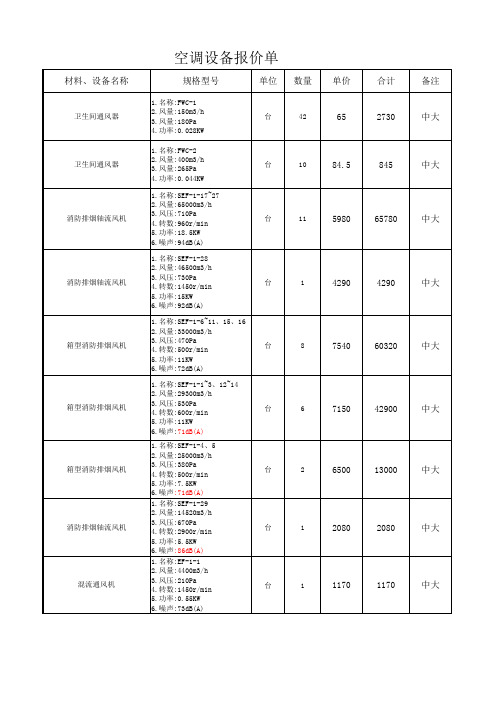
单位
数量
单价
合计
备注
卫生间通风器
台
42
65
2730
中大
卫生间通风器
台
10
84.5
845
中大
消防排烟轴流风机
台
11
5980
65780
中大
混流通风机
台
2
2145
4290
中大
混流通风机(防爆型)
台
2
1105
2210
中大
混流通风机
台
2
1560
3120
中大
混流通风机
台
2
1820
3640
中大
混流通风机
台
2
1950
单位
数量
单价
合计
备注
卫生间通风器
台
42
65
2730
中大
卫生间通风器
台
10
84.5
845
中大
消防排烟轴流风机
台
11
5980
65780
中大
全热回收新风机换气机
台
4
18786
75143
天加(含 开关)
全热回收新风机换气机
台
4
15848
63391
天加(含 开关)
全热回收新风机换气机
台
8
32205
257638
1.名称:FP-85 2.风量:850m3/h 3.冷量:4.5KW 4.热量:6.8KW 5.功率:0.075KW 6.噪声:42dB(A)
台
25
829
20718
天加
风机盘管(带温控开关)
国家标准《碳化钨粉》-(预审稿)编制说明
GB/T 4295--2008《碳化钨粉》国家标准编制说明一、工作简况1.1 任务来源根据国家标准委员会《国家标准委关于下达2016年第三批国家标准制修订计划的通知》(国标委综合[2016] 76号)的要求,由自贡硬质合金有限责任公司负责修订国家标准《碳化钨》,该项目计划编号为20161664-T-610,计划完成年限:2019年。
1.2 简况本标准规定了碳化钨粉末的技术要求、试验方法、检验规则、标志、包装、运输、储存及订货单(或合同)内容。
本标准适用于生产硬质合金等用的碳化钨粉。
GB/T 4295—2008《碳化钨粉》自2008年制定实施以来,对国内的生产企业起到了规范性的积极作用。
随着产品在高新技术领域应用的不断深入,使用单位对产品提出了更高的要求。
因此,在积极采用国内外先进标准的同时,根据我国企业生产的实际水平、设备能力、检测手段以及应用发展趋势,有必要对其进行修订。
1.3 起草单位情况及主要工作过程1.3.1 起草单位情况自贡硬质合金有限责任公司(简称“自硬公司”)始建于1965年的三线建设时期,是中国自主创建的第一家大型硬质合金和钨钼制品生产企业,是五矿集团旗下硬质合金及钨钼产业的核心成员之一。
公司在职员工约3000人,现有总资产22亿元,建有硬质合金、硬面材料、钨钼制品三大产品科研、生产、经营和出口基地。
产品广泛应用于机械、冶金、石油、矿山、建筑、电子、航天航空等领域。
综合实力居国内前列,先后获得“五一劳动奖状”、“中国名牌产品”、“中国驰名商标”等荣誉称号。
公司拥有100多项科研成果和国家级重点新产品,获得授权有效专利160多项。
公司通过了ISO9001:2000质量体系、ISO14001环境管理体系、OHSAS18001职业安全健康体系认证,质量检测体系获得中国合格评定国家认可委员会(CNAS)认可,计量控制体系获得国家ISO10012测量管理体系认证。
1.3.2 主要工作过程为做好本标准的修订工作,自贡硬质合金有限责任公司成立了专门的《碳化钨》国家标准制定工作组。
FWC特灵

HFCFFWCFWD风机盘管机组HFCF 风机盘管机组转速高速中速低速高速中速低速高速中速低速高速中速低速高速中速低速高速中速低速高速中速低速高速中速低速高速中速低速型号020304050608101214风量m 3/h 34026019051038026068049034085067043010207104801360102071017001260850204016701150238017901300冷量kW2.161.681.253.522.752.044.253.40 2.645.224.443.296.184.943.717.566.354.849.477.955.9711.089.757.6512.8111.149.22热量kW 3.372.742.125.164.023.04 6.465.10 3.888.026.744.819.30 7.35 5.30 12.2210.267.8215.5112.879.6218.0615.8912.120.5117.8414.15功率w 2318152920174332276730257759481171008514211087173140114195170148噪音dB(A)35 272332232137292342352543332645 39 32 46 38 27 50 44 35 524639冷量kW 2.10 1.64 1.22 3.41 2.66 2.05 3.70 2.96 2.29 5.09 4.33 3.21 5.81 4.65 3.49 7.51 6.31 4.81 9.66 8.11 6.09 11.58 10.19 7.99 12.65 11.01 9.11热量kW 3.27 2.65 2.06 5.35 4.17 3.16 5.70 4.50 3.42 7.89 6.63 4.73 9.12 7.20 5.20 12.31 10.40 7.88 15.66 13.00 9.71 18.58 16.35 12.45 21.15 18.40 14.59功率w 443429563933644840858069927057145124105176136108214173141286257217噪音dB(A)413828423526453827464031474234504538514434545041564938水流量l/s 0.1080.172 0.209 0.256 0.299 0.368 0.459 0.539 0.625 水压降kPa 103319273822283849水流量l/s 0.1030.166 0.181 0.250 0.283 0.367 0.471 0.565 0.621 水压降kPa 123115263723313849标准静压型(机外余压12Pa )高静压型(机外余压50Pa )注: 1. 制冷工况:进风干/湿温度DB/WB:27/19.5°C ,冷冻水进出水温度:7/12°C 。
钢铁工业的水足迹计算

中国是世界上生产钢铁最多的国家。
这个重工业的特点是重要的水耗量和数量众多的雨水有关的环境灾害。
这这项研究中,我们提出了水足迹的使用,以代替常规指标(每顿钢铁的淡水消耗(FMC),或者每吨钢铁的水耗量(WC))。
以中国东部的一个钢厂为例,我们建立了一个水足迹计算模型,包括直接和虚拟水足迹。
然后利用系统边界分析方法提出建立一个常见、可行的工业水足迹评价方法。
具体地说,我们从生命周期评价的角度分析了钢铁行业的特点。
以水足迹计算的结果为基础进行水风险评估。
选中钢厂水消费(蓝水)足迹为2.24*107m3,包括虚拟水和2011年为6.5 * 108m3的理论水污染(灰水)足迹,表明这个企业对水环境构成了严重的威胁。
对蓝水和灰水足迹分别进行计算以提供更详细的水风险信息,而不是添加对环境没有那么重要的这两个指标。
1 简介水和能源对炼钢来说是至关重要的组成部分。
中国铁的主要生产地,因此对国际钢铁工业的发展起到了重要的作用。
表1列举了2008到2010年的钢铁主要生产国的钢产量。
2004年,中国钢铁行业水耗量是4*109m3,占了年度工业水耗量的10%。
钢铁行业通过废水排放严重影响了当地的水环境。
废水中有毒污染物种类很多,比如未溶解金属包括Cd、石油衍生物、挥发性酚和砷等等。
因此,钢铁行业严重影响了当地、地区乃至全球的水资源,并且面临很高的水风险。
现在,钢铁行业使用吨钢淡水耗量(FWC),吨钢水耗量(WC)等指标。
吨钢淡水耗量指生产1吨钢铁消耗的淡水量。
这里面的淡水指的是进入钢厂水系统的新鲜自来水,地下水和地表水,不包括用于冷却的循环水。
吨钢水耗量值生产1吨钢铁所用的所有水,包括回收水和再生水。
FWC和WC相对来说简单实用。
但是它们仅仅反映了钢铁行业的直接水耗量,并且忽略了虚拟水耗量和废水污染。
虚拟水的概念由Allan于1998年提出,指的是输入当前进程所需要生产的水。
举个例子,对钢厂来说,发电所需要的水会被认为是这个企业的虚拟水。
南自厂FWC 2000型分布式网络自动化测量系统说明书

FWC2000型分布式网络测量系统目录一、FWC2000型分布式网络测量系统概述 ---------------------------------------------- 11.概述 ----------------------------------------------------------------------- 1 2.典型系统配置 --------------------------------------------------------------- 2 二、自动化监测设计选型 ------------------------------------------------------------ 31.自动化监测设备选择 --------------------------------------------------------- 3 2.计算机及其外设选择 --------------------------------------------------------- 3 3.FWC2000测量单元配置 ------------------------------------------------------- 3 4.供电电源的选择 ------------------------------------------------------------- 3 5.通讯介质的确定 ------------------------------------------------------------- 3 6.避雷要求及其他 ------------------------------------------------------------- 3 三、FWC 2000 测量单元 ------------------------------------------------------------- 51.基本组成 ------------------------------------------------------------------- 5 2.几何尺寸、重量 ------------------------------------------------------------- 5 3.外形 ----------------------------------------------------------------------- 5 四、AMU系列测量模块 -- ------------------------------------------------------------ 61.AMU-1008(AMU-1016E)差动电阻式(压阻式)仪器测量模块 ------------------------- 6 2.AMU-2008(AMU-2016E)振弦式仪器测量模块 ------------------------------------ 10 3.AMU-3008(AMU-3016E)应变片式仪器测量模块 ---------------------------------- 13 4.AMU9001防雷电源管理模块 -------------------------------------------------- 16 5.AMU9485防雷RS485通讯模块 ------------------------------------------------ 16 6.AMU9485L光纤通讯模块 ----------------------------------------------------- 16 五、FWC2000安全监测系统软件 ----------------------------------------------------- 171.概述 ---------------------------------------------------------------------- 17 2.软件主要特点 -------------------------------------------------------------- 17 3.软件结构与主要功能模块 ---------------------------------------------------- 18一、 FWC 2000型分布式网络测量系统概述1.概述FWC 2000型分布式网络测量系统(以下简称测量系统),是国家电力公司南京电力自动化设备总厂南京水利电力仪器工程有限责任公司推出的用于工程安全自动化测量的新一代产品。
中文版工作家庭平衡量表的信效度研究
mann 等人编制的员工总体工作满意度问卷 , 共有
3 个项目。心理健康采用李虹等修订的 GHQ-20 , 包括自我肯定、 忧郁和焦虑三个维度, 共 20 个项目。 1.2
[17]
对正式研究数据进行验证性因素分析, 并比较 了单因素模型 (所有项目测的是工作家庭平衡一个 维度) 、 二因素模型 (工作家庭冲突和工作家庭促进 是两个不同维度) 和四因素模型 (工作侵扰家庭、 家 庭侵扰工作、 工作促进家庭和家庭促进工作是四个 不同维度) 。所得结果见表 2。 从表 2 的结果可知, 四因素模型的各项拟合指
受到研究者的重视。在早期研究中, 研究者关注更 多的是二者关系的消极方面——工作 - 家庭冲突
过去的 30 多年里, 工作与家庭的关系问题一直
positive spillover) [5]、 工作 - 家 庭 丰 富 (work-family en⁃ richment) [8,9] 和工作 - 家庭增益 (work-family enhance⁃ ment)[10]等。 family facilitation) 是指一个角色的经历能提高另一 个角色的生活质量, 其中角色质量主要表现为角色 绩效或正性情感方面[5]。他们进一步指出, 工作-家 庭促进包括两个方面: 家庭中获得的资源 (能力的发 展, 弹性制, 身体和心理资本, 物质资源) 或者直接提 高工作绩效 (指工具性途径) , 或者间接提高工作正 性情感 (指情感性途径) , 即家庭促进工作 (familyto-work facilitation, FWF) ; 在工作中获得的资源 (能 力的发展, 弹性制, 身体和心理资本, 物质资源) 或者 作促进家庭 (work-to-family facilitation, WFF) 。 直接提高家庭绩效或间接提高家庭正性情感, 即工 Barneet 认为, 对工作与家庭关系的完整理解应 Grzywacz 和 Marks 指出, 工作-家庭促进 (work-
金刚石工具粉末

注:如用户对化学成分、粒度组成和松装密度另有要求,由供需双方商定。
注:如用户对化学成分、粒度组成和松装密度另有要求,由供需双方商定。
◆中文名称:羰基铁粉简称CIP◆英文名称:Carbonyl Iron Powder◆CAS编码:7439-89-6, UN 3089◆分子式:Fe◆分子量:55.845羰基铁粉最早由德国人发明,二战时德国的工厂被美国征收,从此美国也开始生产羰基铁粉。
目前德国BASF公司拥有世界上最大,最先进的羰基铁粉生产线。
羰基铁粉是通过CO与铁在高温高压下反应,生成5羰基铁油状物,经低压分离后得到产品。
经退火防氧化处理即可出货。
当温度为200℃,200bar的条件下羰基合成反应式如下Fe+5CO Fe(CO)5羰基铁在300℃,1bar的条件下分解为Fe和COFe(CO)5 Fe+5CO在分解过程中,因为Fe 有催化CO与CO2 反应的作用,通常采用通NH3 作为保护气体来抑制该反应。
这样一来羰基铁粉中就不可避免的会有N元素的存在。
从旋风收集器中收集到的产品一般铁含量约在97%左右,其中C和N的含量均小于1%。
由于有Fe2O3,Fe3N 等杂质的存在,同时,铁粉表明也会对CO和NH3气体有一定的吸附,这些因素造成铁粉硬度比较大,通常被称之为硬粉。
将铁粉用H2气体还原1小时,铁含量将提高到99.0%左右,同时其他元素的含量也将明显降低。
这种还原过的羰基铁粉,硬度稍低,也被称之为软粉。
羰基铁粉活性很大,正常情况放置一段时间后,因为熵的增加,会发生自动团聚。
发生团聚的铁粉颗粒度增加,颗粒粘粘,对于注射成型应用有比较大的影响。
目前市场上质量最好的羰基铁粉为德国BASF公司生产。
羰基铁粉对工艺的要求非常高,5羰基铁分解时温度变化3度,气体流量增加5%就能明显改变羰基铁粉粒度及碳含量。
外观:深灰色粉末。
◆基本用途:1.传统粉末冶金及注射成型:传统粉末冶金中的高比重合金,需要采用活性较大的铁粉作为烧结中的液相,形成较为连续的粘结相,抑制脆性相的产生,从而获得高致密度或全致密的高性能产品。
JBL AC2215 95 双向喇叭说明书
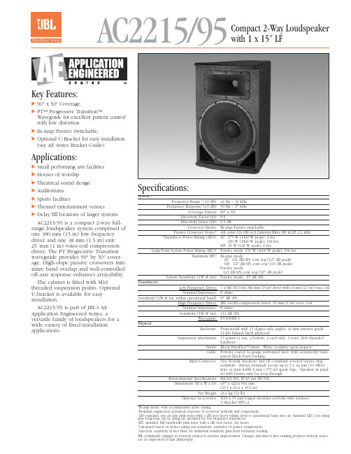
AC2215/95Compact 2-Way Loudspeaker with 1 x 15" LFKey Features:᭤90°x 50°Coverage.᭤PT™ Progressive Transition™Waveguide for excellent pattern control with low distortion.᭤Bi-Amp/Passive Switchable.᭤Optional U-Bracket for easy installation (see AE Series Bracket Guide).Applications:᭤Small performing arts facilities ᭤Houses of worship᭤Theatrical sound design ᭤Auditoriums ᭤Sports facilities᭤Themed entertainment venues᭤Delay/fill locations of larger systems AC2215/95 is a compact 2-way full-range loudspeaker system comprised of one 380 mm (15 in) low frequency driver and one 38 mm (1.5 in) exit/25mm (1 in) voice-coil compression driver. The PT Progressive Transition waveguide provides 90°by 50°cover-age. High-slope passive crossovers min-imize band overlap and well-controlled off-axis response enhances arrayability. The cabinet is fitted with M10threaded suspension points. Optional U-bracket is available for easy installation.AC2215/95 is part of JBL’s AE Application Engineered Series, aversatile family of loudspeakers for a wide variety of fixed installation applications.Specifications:System:Frequency Range 1(-10 dB):42 Hz – 19 kHz Frequency Response 1(±3 dB):50 Hz – 17 kHz Coverage Pattern:90°x 50°Directivity Factor (Q):8.9Directivity Index (DI):9.5 dBCrossover Modes:Bi-amp/Passive switchablePassive Crossover Slopes 2:4th order (24 dB/oct) Linkwitz-Riley HP & LP, 2.2 kHz Transducer Power Rating (AES)3:LF: 275 W (1100 W peak), 2 hrs250 W (1000 W peak), 100 hrs HF:30 W (120 W peak), 2 hrsLong-Term System Power Rating (IEC)4:Passive mode: 250 W (1000 W peak), 100 hrsMaximum SPL 5:Bi-amp mode:LF: 121 dB-SPL cont avg (127 dB peak)HF: 127 dB-SPL cont avg (133 dB peak)Passive mode:121 dB-SPL cont avg (127 dB peak)System Sensitivity 6(1W @ 1m):Passive mode: 97 dB SPLTransducers:Low Frequency Driver: 1 x JBL M115-8A 380 mm (15 in) driver with 63 mm (2.5 in) voice coil Nominal Impedance:8 ohmsSensitivity 6(1W @ 1m, within operational band):97 dB SPLHigh Frequency Driver:JBL 2412H compression driver, 25 mm (1 in) voice coil Nominal Impedance:8 ohms Sensitivity (1W @ 1m):112 dB SPLWaveguide:PT-F95HF-1Physical:Enclosure:Trapezoidal with 15 degree side angles, 16 mm exterior grade11-ply Finnish birch plywoodSuspension Attachment:15 points (4 top, 4 bottom, 2 each side, 3 rear), M10 threadedhardwareFinish:Black DuraFlex™ finish. White available upon request.Grille:Powder coated 14 gauge perforated steel, with acoustically trans-parent black foam backing.Input Connector:NL4 Neutrik Speakon ®and CE-compliant covered barrier stripterminals. Barrier terminals accept up to 5.2 sq mm (10 AWG)wire or max width 9 mm (.375 in) spade lugs. Speakon in paral-lel with barrier strip for loop-through.Environmental Specifications:Mil-Std 810; IP-x3 per IEC529.Dimensions (H x W x D): 637 x 422 x 504 mm(25.1 x 16.6 x 19.9 in)Net Weight:23.6 kg (52 lb)Optional Accessories: M10 x 35 mm forged shoulder eyebolts with washersU-Bracket MTU-2Bi-amp mode, with recommended active tuning.Resultant engineered acoustical response of crossover network and components. AES standard, one decade pink noise with 6 dB crest factor within device's operational band, free air. Standard AES 2 hr rating plus long-term 100 hr rating are specified for low-frequency transducers.IEC standard, full bandwidth pink noise with 6 dB crest factor, 100 hours.Calculated based on power rating and sensitivity, exclusive of power compression.Anechoic sensitivity in free field, no additional sensitivity gain from boundary loading.JBL continually engages in research related to product improvement. Changes introduced into existing products without noticeare an expression of that philosophy.᭤AC2215/95 Compact 2-Way Loudspeaker with 1 x 15" LFHorizontal 1/3 Octave PolarsSS AC2215/95CRP 10M 7/02᭤AC2215/95 Compact 2-Way Loudspeaker with 1 x 15" LFVertical 1/3 Octave PolarsJBL Professional8500 Balboa Boulevard, P.O. Box 2200Northridge, California 91329 U.S.A.©Copyright 2002 JBL ProfessionalAHarman International Company。
深圳万物安全科技有限公司介绍企业发展分析报告

Enterprise Development专业品质权威Analysis Report企业发展分析报告深圳万物安全科技有限公司免责声明:本报告通过对该企业公开数据进行分析生成,并不完全代表我方对该企业的意见,如有错误请及时联系;本报告出于对企业发展研究目的产生,仅供参考,在任何情况下,使用本报告所引起的一切后果,我方不承担任何责任:本报告不得用于一切商业用途,如需引用或合作,请与我方联系:深圳万物安全科技有限公司1企业发展分析结果1.1 企业发展指数得分企业发展指数得分深圳万物安全科技有限公司综合得分说明:企业发展指数根据企业规模、企业创新、企业风险、企业活力四个维度对企业发展情况进行评价。
该企业的综合评价得分需要您得到该公司授权后,我们将协助您分析给出。
1.2 企业画像类别内容行业软件和信息技术服务业-软件开发资质一般纳税人产品服务是:计算机信息系统集成,计算机软硬件、办1.3 发展历程2工商2.1工商信息2.2工商变更2.3股东结构2.4主要人员2.5分支机构2.6对外投资2.7企业年报2.8股权出质2.9动产抵押2.10司法协助2.11清算2.12注销3投融资3.1融资历史3.2投资事件3.3核心团队3.4企业业务4企业信用4.1企业信用4.2行政许可-工商局4.3行政处罚-信用中国4.4行政处罚-工商局4.5税务评级4.6税务处罚4.7经营异常4.8经营异常-工商局4.9采购不良行为4.10产品抽查4.11产品抽查-工商局4.12欠税公告4.13环保处罚4.14被执行人5司法文书5.1法律诉讼(当事人)5.2法律诉讼(相关人)5.3开庭公告5.4被执行人5.5法院公告5.6破产暂无破产数据6企业资质6.1资质许可6.2人员资质6.3产品许可6.4特殊许可7知识产权7.1商标7.2专利7.3软件著作权7.4作品著作权7.5网站备案7.6应用APP7.7微信公众号8招标中标8.1政府招标8.2政府中标8.3央企招标8.4央企中标9标准9.1国家标准9.2行业标准9.3团体标准9.4地方标准10成果奖励10.1国家奖励10.2省部奖励10.3社会奖励10.4科技成果11土地11.1大块土地出让11.2出让公告11.3土地抵押11.4地块公示11.5大企业购地11.6土地出租11.7土地结果11.8土地转让12基金12.1国家自然基金12.2国家自然基金成果12.3国家社科基金13招聘13.1招聘信息感谢阅读:感谢您耐心地阅读这份企业调查分析报告。
November 2022 Page 1 8 COP 3 软件安装指南说明书

COP 3 DocumentationInstallation GuideContentDisclaimer 1 Purpose 1 Required configuration 2 Installation procedure 2 Launch COP 5 Install / activate licence 5 Installation of network licences 7DisclaimerDue to the complexity of the calculation methods used, this software is only intended for professional users active in the domain of steel constructions who are fully aware of the possibilities, inadequacies and suitability of the software for the various concrete appli-cations. THE USER USES THIS SOFTWARE ON HIS OWN RESPONSIBILITY AND AT HIS OWN RISKS.This software was developed by Feldmann + Weynand GmbH (hereinafter F+W) in co-operation with Feldmann + Weynand Engineers GmbH (hereinafter FWC). No right or warranty is granted to the user of the software. All rights (including intellectual property) continue to belong exclusively to F+W and FWC respectively. F+W and/or FWC do not assume any liability towards the user of this software.The user of this software undertakes to hold F+W and FWC free and harmless from any claim and any direct and/or consequential damages.BY USING THIS SOFTWARE, THE USER OF THIS SOFTWARE CONFIRMS THAT HE IS AWARE OF THE ABOVE TEXT AND THAT HE THEREBY ACCEPTS ALL LE-GAL CONSEQUENCES AND OBLIGATIONS RESULTING FOR HIM THEREFORE.Note:This text is an English translation of the German disclaimer. In case of any ambiguities, the disclaimer in German shall always apply.PurposeCOP is a special software package to design joints according to the European standard EN 1993 (Eurocode 3), and here in particular EN1993-1-8.The application of the design methods for joints is rather complex and long to apply.Therefore design tools for practitioners are required for a safe and economic application of the Eurocode 3. The software COP has been developed in order to provide the de-signer a simple tool to perform a full set of design checks according to EN 1993-1-8 for the design of joints.The present documentation gives a comprehensive overview on how to install the soft-ware.Required configurationThe software is designed for Microsoft Windows. The software has been tested on Windows 10. It should also still run under Windows 7, but this is not assured. To install and run the software 500 MB memory (minimum) and 400 MB hard disk space is re-quired.The software is developed for the Microsoft .NET Framework. The .NET Framework version 4.6 or higher must be installed.Installation procedureIn order to install the COP software on a PC execute the provided installation file “COP_x.y.z_Setup”(“x.y.z”representing the actual version number). The following screen appears:Select a language for the installation procedure and press "OK" to continue.The COP Setup Wizard will start.Press “Next” to continue.On the following screen you can specify the installation folder.Press “Next” to continue.To protect your software, the licence server 'CodeMeter' is used. COP installs a third party software called CodeMeter including a service called “CodeMeter Runtime Serv-er”, hereinafter also referred to as “license server”. CodeMeter is a licensing and digital rights management system from Wibu-Systems ().As a local service, the licence server manages licences on the local PC and, at the same time, it enables as a 'network client' the access to licences available in the net-work. In addition, the licence server can be configured as a 'network server' and thus make network licences available throughout the network.If the CodeMeter software is already installed on your machine, COP will update the software if necessary. If the already installed CodeMeter software has a newer version, COP will of course skip the installation of CodeMeter.On the next screen you may decide how to configure the “license server”. In most cas-es, you would select the first option “Run as ‘local service’ or ‘network client’” (default). Only in case you bought a network license and you are installing COP on a machine that will (also) provide your license to other machines, select the second option “Run as ‘network server’”. Detailed instructions for the installation of network licences can be found below in the chapter “Installation of network licences”.Note: If the licence server is already installed on this computer and configured as a network server, the configuration cannot be changed here since the licence server may also beused by other software. However you can change the configuration later using theCodeMeter Control Center.Select the desired configuration and press “Next”to continue. The “Ready to Install” page will appear.If all settings are correct, click “Install” to start the installation process.Press "Cancel" to terminate the installation procedure here.After pressing “Install”, t he installation procedure will start to install COP on your com-puter. When done, so the following screen will appear.Click “Finish” to exit the setup program. Unless you unselect the option “Start COP now”, COP will be started after the setup program is terminated.Launch COPTo launch COP, click on the COP icon on your desktopor select “Windows Start | Feldmann + Weynand | C OP”The first time COP is started, the welcome window appears. Please confirm the dis-claimer. COP starts and displays the page “New - Create a new project”.Install / activate licenceIf you have purchased a new COP licence, you still have to install or activate this li-cence after installing COP.COP is protected to prevent illegal copying. Two types are available for the software protection:S OFTWARE-BASED PROTECTION (“LICENCE FILE”)With the software-based protection, the software is protected by installing a licence file on the local computer (or on a licence server in the case of a network licence). Please note that the software-based protection (licence file) is bound to the computer hardware and therefore cannot be transferred to another computer. Likewise, this type of protec-tion cannot be used in virtual environments.To create a new licence as software-based protection (i.e. a licence file), we need a licence request file from you. The licence request file contains characteristics of thehardware on which the licence file should be installed. Start COP and open the page “Licence” in the menu “File”. There, click on the button “Request licence...” to start the “Wizard for creating licence request files”. Select any directory in which the licence re-quest file should be saved and click on “Generate licence request file”. Please send the generated licence request file (*.WibuCmRaC) by email to ******************.1. Request licenceWe will then send you an email with your personal licence activation file, which you can install on your computer using the licence activation wizard integrated in COP. Please note: The licence file can only be installed / activated on the computer on which the licence request file was created.Save the licence activation file (*.WibuCmRaU) in any directory. Start COP and open the “Licence” page in the “File” menu. There you start the “L icence activation wizard” by clicking on the button “Activate/update licence...”. Use the “Browse” button to select the directory in which you have saved the licence activation file and then click on the “Im-port licence activation file” button.2. Activate licenceCOP will now import and activate the licence. When the process is complete, the li-cence is automatically recognised by COP and the corresponding licence information is displayed at the top of the page.H ARDWARE-BASED PROTECTION (“D ONGLE”)After purchasing a licence with hardware-based protection, we will send you a ready-configured dongle with your personal licence by post. Plug the dongle into a USB port on your computer (or, in the case of a network licence, into a USB port on the licence server). After the installation of COP, COP will automatically recognise the dongle.Note:You can use the dongle at any computer on which COP is installed, i.e. the li-cence can easily be transferred from one computer to another.Installation of network licences1.G ENERALAll the steps to install COP network licences are explained below. For this purpose, a network server and any number of local clients (network clients) will be installed. The network server provides available licences that are recognised by the network clients automatically.To install both the network server and network clients, please use the same COP setup file, which you can download at any time from the customer area on the COP website.2.N ETWORK S ERVER –I NSTALLATION AND C ONFIGURATION2.1 Software based Protection (“Licence File”)Installing SoftwareFirst install COP on a computer which you would like to use as network server. This can be any Windows machine, i.e. also a workstation. However, it should be a computerthat can always be accessed within the network. During installation, select in the setup wiz ard on page “Licence server configuration” the option “Run as ‘network server’”. Note: Please note that a software based protection (licence file) cannot be installed on virtual machines. To install COP on a virtual machine, you need a hardware based protection(dongle).Install / activate licenceIf you have purchased a new COP licence, you still have to install or activate this li-cence after installing COP. Detailed instructions can be found above in the chapter "In-stall / activate licence".Note: The network server that has now been installed can also be used as a workstation for COP. Install COP now on any number of additional computers as described below inthe chapter “3. Network Clients – Installation and configuration”.2.2 Hardware based Protection (“Dongle”)Installing SoftwareFirst install COP on a computer which you would like to use as network server. This can be any Windows machine, i.e. also a workstation. However, it should be a computer that can always be accessed within the network. During installation, select in the setup wizard on page “Licence server configuration” the option “Run as ‘network server’”. Start COP afterwards. COP will detect the dongle automatically as soon as you connect the dongle to your computer.Note: The dongle can be plugged in or removed at any time. The current state is always rec-ognised by all clients in the network. Attention! If you remove the dongle when a net-work client is using one licence of this dongle, the network client loses the licence andall program features linked to this licence will be locked. However, the project can besaved, so that no data is lost. If you plug in the dongle again, the network client will au-tomatically find the licence again, and you can continue using COP without any re-striction.3.N ETWORK C LIENTS –I NSTALLATION AND CONFIGURATIONInstall COP on each of your client computers by executing the COP setup file. In the setup wizard on the page “Licence server configuration” select the option “Run as ‘local service’ or ‘network client’” (default setting). Start CoP afterwards.In order to find the network licence of COP, the option "Search for network licences" in the menu "File" on the page "Licence" must be activated. After a new installation of COP this option is always activated. As soon as the network server is ‘visible’ for this client computer, COP will find the licence server automatically. The licence server will then immediately allocate a licence for this client, provided that not all licences are in use at this moment.。
玻璃钢夹砂管施工的接缝处理与试压技术
玻璃钢夹砂管施工的接缝处理与试压技术邵成猛;王军辉【摘要】玻璃钢夹砂管在非压力管道中有着广泛的应用,但很少应用于压力管道.青草沙凌桥支线C3标工程第一次将玻璃钢夹砂管应用于长距离压力曲线管道之中,以此工程为背景,对玻璃钢夹砂管的连接形式进行了探讨,开展了接缝的强度和水压试验,总结了接缝处理技术流程和施工要点,设计了闭水试验支撑系统,对管道整体进行了泵压试验,结果证明将玻璃钢夹砂管用于压力管道是可行的.该研究可为今后玻璃钢夹砂管应用于压力管道施工提供有益的借鉴.%Class fiber reinforced plastic pipe with motar (FRPM) is widely used in non-pressure tunnel, but it is not widely used in pressure tunnel. In this paper, glass FRPM was first time used in the long distance pressure tunnel of Qingcaqsha Lingqiao extension. The connection form of glass FRPM was analyzed. The joint strength and water pressure tests were carried out. The joint processing procedures and construction technical were summed up and a closed water test support system was designed. The result indicates that glass FRPM can be used in pressure tunnel. The research is a useful reference for similar projects.【期刊名称】《净水技术》【年(卷),期】2012(031)004【总页数】5页(P129-133)【关键词】玻璃钢夹砂管(FRPM);连接;接缝处理;闭水试压【作者】邵成猛;王军辉【作者单位】中铁十六局集团有限公司,北京100018;上海申通地铁集团有限公司,上海201103【正文语种】中文【中图分类】TU745.3随着城市轨道交通、水利等建设的蓬勃开展,尤其是城市给排水系统的大力建设,顶管法施工技术在我国得到了越来越广泛的应用[1-6]。
车间设计—粉末冶金

计算说明书课题年产130吨硬质合金物料平衡计算院(系)冶金工程学院专业金属材料与热处理技术班级金属101姓名学号2012 年11 月第1章前言物料平衡计算是进行硬质合金生产前必不可少的一部分。
物料平衡计算的目的是用数学分析的方法计算每一道工序产品与生产该产品所需的原料、辅助材料之间的数量平衡关系。
物料平衡计算是确定设备、劳动力、生产面积、运输工具和各种动力等需要量的计算依据。
在冶金物料平衡计算中,通常采用两种方法:一种是按工序工艺流程“自上而下”的计算方法,另一种是“自下而上”的计算方法。
若规定出工厂的产品数量或在生产过程中若所以返回料和进行残料处理时,一般采用“自下而上”的方法,若规定出原材料处理量则采用“自上而下”的方法比较好。
“自上而下”的方法是根据生产过程的工序顺序,从第一个工序开始顺次计算各个工序的成品产量与损失量,最后综合整个生产过程中各个工序的产品数量和所以损失。
在这里,我采用的是“自下而上”的计算方法,即根据工艺流程从最终的成品产量开始向上逐步计算出整个生产过程开始所需要的原料为止。
工艺流程是:制粉→制备混合料→压制、半检→烧结、加工。
所以从产品量开始逐步向上计算。
其具体步骤为:(1)由本工序已知的产出量和产出率计算出本工序的进料量。
(2)由本工序的可返回损失率和不可返回损失率,计算出本工序的可返回损失量和不可返回损失量。
(3)由本工序的进料量和可返回料量计算出本工序的实际进料量。
(4)如果本工序实际进料量为多元组分,则应按每一组元的成分的百分数分别计算出它们的进料量。
(5)当原材料中金属含量不是100%时,一般应按原料成分直接进行计算。
为了简化计算过程也可首先按原料中所含纯金属量进行计算,然后将其计算结果根据金属在原料中的含量换算成原料的进料量。
(6)所需数字全部计算完毕后,为了清楚和验算的差错,应分别列出各工序的平衡列表。
在平衡表中,进料量总和与出料量总和应该相等。
否则说明计算有差错应予以改正使之平衡。
CT二次负载计算方法
一、保护CT运行要求1、继电保护及安全自动装置(包括微机故障录波器等)电流必须取自保护级烧组(P或D/B)。
严禁取自计量烧组(0.2或0.5/1.0/3.0)。
2、继电保护及安全自动装置CT(包括主变套管、中性点、棒间隙等)在一次最大短路电流对应的极限误差不得超过标称值(5%或10%)。
3、新建发、变电工程应使用IA制CT。
这样可允许更大的二次负载和短路电流,更能适应电网的不断发展。
4、220KV及以上系统双重化配置的两套保护装置,其电流、电压回路必须彻底独立,严禁两套保护装置之间有任何电气联系。
同一套表保护装置主、后备保护可以共享数据。
5、、110KV及以下系统配置的单套保护装置,其主、后备保护电流回路必须彻底独立。
二、电流互感器(CT)的误差由于励磁电流的存在,二次电流与换算后的一次电流不但幅值上不相等,而且相位上也不相同,这就造成了CT的误差。
由于一、二次电流的不等造成的电流误差,称为比误差;由于相位不同造成的角度误差称为相差。
根据有关规定,在允许二次负载、允许最大短路电流饱和倍数情况下,比误差不大于5%-10%,相差不大于7·。
CT的误差与流过CT的一次短路电流,CT的变比、容量、二次负载、接线方式、铁芯结构及材料等多种因素密切相关。
合格的CT是继电保护、安全稳控装置正确动作的前提条件,也是电网安全、稳定运行基本保障。
保护装置不正确动作之后;原因不明。
其中一个重要原因与CT饱和有关。
由于故障录波不完善,保护信息部完整(微机化率低活性能不完善),事故分析不到位,上述原因长期被忽视,日月积累,今年来问题在110KV及以上系统开始显露,已造成多起电网事故(包括配网事故),教训是非常深刻的。
三、减小误差的主要措施;励磁电流是造成CT的误差的主要原因,因此要减小误差就必须在减小励磁电流着手。
主要措施如下:1、在CT的设计、研发阶段采用高导磁率的铁芯材料,增大铁芯截面、缩短侧路长度,尽量提高CT的饱和倍数。
