5700使用说明书
5700操作手册

第一章ECLIPS-5700 硬件系统第一节系统简介一、ECLIPS 地面系统概述ECIPLS-5700 数控测井地面系统是美国ATLAS 公司90 年代开发生产的新一代测井地面数据采集系统。
该系统采用功能很强的工作站作为主机及高速数据通讯的WTS 遥传系统。
软件以多任务、多用户的UNIX 操作系统为基础,大量采用现代图象处理显示技术。
通过配备阵列化、成像化及大信息量为特点的新一代井下仪器,实现以多参数采集、多任务分时处理为特点的实时测井数据采集、控制和处理。
为客户提供常规和成像测井图件及记录数据,并能完成井壁取心、射孔和测井数据的现场通讯传输及现场测井数据的初步分析处理等服务。
图1.1.1 为ECLIPS-S 型地面系统外观图。
ECLIPS5700 系统通过采用先进的数字数据采集技术和先进的图象显示技术来保证测井数据的质量。
其具有如下特点:1、该系统记录的数据包括仪器的原始信号、经过刻度的工程值和处理后的数据。
由于记录了仪器的原始信号,所以出现刻度误差时可以用不同的参数重新处理测井资料。
2、刻度值和校验值全部都可显示出来,由操作员确认,超差数值会闪亮,引起操作员的注意。
3、可采用多窗口显示核测井仪器所获得的能谱及声波类仪器所获得的波形。
通过用户控制这些窗口既可显示原始数据,也可显示处理过的数据,以便操作员进行实时测井数据的质量控制。
4、可以在主要测井曲线上实时重叠显示重复曲线,以验证曲线的重复性。
5、实时绘制交会图,使操作员可以根据预期的模型验证测井响应的正确性。
6、实时环境校正,以消除测井质量控制过程中操作员的主观评估成分。
7、实时相似校正,以验证声波波形资料的完整性。
8、采用人员安全和数据保护系统。
9、通过采用高端的计算机技术及冗余设计简化数据采集和处理过程,缩短现场工作时间并保证系统的可靠性。
ECLIPS 系统服务平台可用于全部以WTS 方式传输和以传统的电缆遥测传输(3508,3506,3504)的下井仪器。
5700使用注意事项

5700使用注意事项一.静态作业注意事项1.静态观测时,开机后等待接收机跟踪大于四颗以上卫星(即卫星跟踪灯慢闪)后,按压数据记录按钮;一定要保证数据记录灯亮,否则没有记录数据。
2.一个时段观测结束后,应先按压数据记录按键,关闭数据采集;然后关闭接收机电源。
二.接收机使用注意事项1.连接Lemo电缆时,要确保接收机端口的红点与电缆接头对齐。
千万不要用力插电缆,以防损坏接头的插脚。
2.断开Lemo电缆后,用滑动轴环或系索拉住电缆,然后从端口直拔电缆接头,不要扭动接头或拉拽电缆。
3.要安全地连接TNC电缆,把电缆接头与接收机插座对齐,再把电缆接头小心地插到插座上,直到完全吻合为止。
4.5700放入内置电池,让电池正面向着袖珍闪存/USB的门。
电池下侧有一个中间凹槽,此凹槽用来作对齐线,以便把电池准确地插到接收机内。
5.5800内置电池放到电池舱内时,确保接触点的位置准确地与接收机的接触点对齐。
把电池和电池舱作为一个整体滑入到接收机内,直到电池舱安置到位并卡定为止。
6.收起电缆时,一定要把电缆盘成环状,避免电缆的扭折。
7.夏天工作时,尽量避免仪器直接暴晒在阳光下。
三.5700电池使用注意事项电池不用时会放电(低温情况下放电迅速)。
如果要长时间存放锂电池,在存放前要确认它充满了电,并且应该至少保证每隔三个月重新充电一次。
为了防止电池深度放电,设计时进行了如下考虑:当电池包放电到5.9伏时,5700系统将切换电池或停止吸收电源。
达到深度放电的电池不能再次充电,只能更换。
以下给出了使电池性能最佳化并且延长电池寿命的建议:1.用之前给所有新电池完全充电。
2.不要让电池放电到5伏以下。
外业工作时,当第二块电池电量耗尽时,应该结束测量工作;不要强行继续工作。
3.如果不加外接电源,则不要在接收机或外部充电器中放置电池。
4.长期存放电池时,应把电池从接收机取出,放置于塑料袋内并存放在干燥的环境。
5.如果必须存放电池,在存放前要完全充电。
Trimble 5700 接收机简要操作说明

Trimble 5700 接收机简要操作说明一、操作面板、接口介绍1.注释:Power button:电源开关按钮Data button:数据存贮按钮Logging/Memory LED :数据记录LED指示灯SV Tracking LED :卫星跟踪指示灯Radio/Event marker LED :电台/Event marker指示灯Battery LEDS :电源指示灯(A与B)图一2.电源显示操作电源开关按钮数据存贮按钮打开接收机电源按下至灯亮松开关闭接收机电源按下至灯熄松开开始数据记录按下至灯亮松开停止数据记录按下至灯灭松开删除所有机内存储数据按住持续15秒松开恢复厂家设置按住持续15秒松开删除接收机内置软件按住持续30秒松开格式化PC卡按住持续30秒松开A.数据存储灯B.卫星跟踪灯C.电台LED慢闪:接收到信号D .电池LED指示4.主机接口说明:充电接口图二手簿接口 外接电源或电脑接口外接电源、基站电台数据线接口电台天线馈线接口(流动站)卫星天线馈线接口1. 充电如下图所示图三设备 :数据下载线(串口)、Trimble 电源适配器充电接口 :port2或3(也是外接电源接口) 电源指示灯状态:绿色 充电时间 :8小时使用时间 :静态5小时/只,RTK3.5小时/只2. 静态外业设备主机3台以上(含内置电池及PC 卡) 配套zephry 天线 配套天线馈线配套对点机座及连接器 配套脚架配套测高尺(如果需高程)对应电池口 (Port2或3)数据下载线(串口)电源适配器交流电源线接口1.操作流程A.架设脚架、基座、卫星天线B.连接天线与主机C.对中整平D.量取天线高(如图)E.开机并存储数据注:B、C可互换,但注意保持对中整平效果图四F、等待存储数据至足够G、停止存贮数据、关闭电源H、收仪器点名仪器号起始时间结束时间操作员四、内业数据下载1.连接方式:a.串口连接(图五)B口连接(图六)图五图六2.下载操作(具体见TGO中文说明书)五、内置电池与PC卡操作按下打开向中间压打开。
NikonCoolPix5700使用宝典

NikonCoolPix5700使用宝典没有一款DC是完美的,性能的完美势必带来价格的不完美,反之亦然。
各厂商只能通过突出某方面的特色而提高性价比来赢取某一层面的用户。
对于定位在家用级的nikon CP5700以其著名的品牌、小巧的机身、5M的高象素、8X4的大变焦力、灵便的旋转LCD、大量的用户设置功能等特色而倍受青睐;同时,因为设计理念及定位目标的不同,不可避免的存在一些遗憾,而一些基本功能的缺省也确实影响了用家对这款DC的发挥。
以下从硬件及软件两方面谈谈CP5700的遗憾及其diy改进。
一.硬件方面1.加装滤镜可能是出于缩小机身尺寸的考虑,5700采用了外变焦设计。
这种设计至少带来以下问题:如何加接滤镜;如何避免外物对伸缩镜筒的碰撞;如何防尘防潮。
据说5700本身是带UV镜的,但看不出这UV是可拆卸的;同时,作为半专业级的DC,连基本的CPL都没法装,而nikon本身也不提供解决方案(UR-E8套筒是专为其广角及增倍镜头设计的转接环,不能用于加装滤镜),不能说不是一种遗憾。
至于碰撞及进尘进汽,也许并不会发生,但有这样的耽心总是郁闷。
加接滤镜常有两种方法:一是直接在伸缩镜头上装转接环,滤镜加在转接环上;二是加套筒。
但都必须避免由此而带来的两个新问题:产生成象暗角;使用内闪时,产生阴影。
笔者做过两个套筒:53.5-58及53.5-62,测试的结果是,58mm 的用内闪无阴影,但加UV时广角有严重暗角;62mm的无暗角,但内闪有严重阴影。
尽管套桶可兼顾滤镜、防碰和防尘,也只能放弃了。
这时才明白sony 的707设计成大炮而内闪置于炮筒之上的道理,5700若采用同样的设计,炮桶可要威猛得多!CP5700并不主张在其镜头上直接加接滤镜,所以镜头前端并未留有常规罗纹。
但镜前的一道凹槽,为“不法分子”提供了可乘之机,有人用橡胶圈将转接环卡进凹槽,便可加装滤镜了。
笔者是在凹槽上卡了半圈钢丝环,再将自制的带凹槽的52mm的转接环卡在钢丝环上,很牢固,不易拔出,无暗角亦无阴影。
广州诚敏电子科技有限公司 NHR-5700 系列多回路数字显示控制仪使用说明书

广州诚敏电子科技有限公司1 版本号:5700-110628NHR-5700系列多回路数字显示控制仪使用说明书一、概述NHR-5700系列多回路数字显示控制仪采用了表面贴装工艺,全自动贴片机生产,具有很强的抗干扰能力。
本仪表支持多种信号类型输入,可与各类传感器、变送器配套使用,实现对温度、压力、液位、速度、力等物理量的测量显示,可巡回检测8~16路测量信号,带8路或16路“统一报警输出”、“16路分别报警输出”、统一变送输出”、“8路分别变送输出”功能、485/232通讯等输出功能,适用于需要进行多测量点巡回检测的系统。
三、仪表的面板及显示功能1)仪表外形尺寸及开孔尺寸广州诚敏电子科技有限公司22)显示窗PV 显示窗:显示测量值;在参数设定状态下,显示参数符号 SV 显示窗:显示通道数;在参数设定状态下,显示设定参数值 3)面板指示灯AL1:第一报警指示灯 AL2:第二报警指示灯 AL3:第三报警指示灯 AL4:第四报警指示灯 AL5:第五报警指示灯 AL6:第六报警指示灯 AL7:第七报警指示灯 AL8:第八报警指示灯 AL9:第九报警指示灯 AL10:第十报警指示灯 AL11:第十一报警指示灯 AL12:第十二报警指示灯 AL13:第十三报警指示灯 AL14:第十四报警指示灯 AL15:第十五报警指示灯 AL16:第十六报警指示灯5)标准配线仪表在现场布线注意事项:PV 输入(过程输入) 1、减小电气干扰,低压直流信号和传感器输入的连线应远离强电走线。
如果做不到应采用屏蔽导线,并在一点接地。
2、在传感器与端子之间接入的任何装置,都有可能由于电阻或漏流而影响测量精度。
热偶或高温计输入应采用与热偶对应的补偿导线作为延长线,最好有屏蔽。
RTD (铂电阻)输入三根导线的电阻必须相同,导线电阻不能超过15Ω。
四、通电设置仪表接通电源后进入自检(见右图),自检完毕后,仪表自动转入工作状态,在工作状态下,按压键显示LOC ,LOC 参数设置如下: 1. 1) Loc 等于任意参数可进入一级菜单(LOC=00;132时无禁锁);2) Loc=132,按压键4秒可进入二级菜单;3)Loc=130,按压键4秒可进入时间设置菜单,对于带打印功能的表;4)Loc 等于其它值,按压键4秒退出到测量画面。
5700操作说明书

3.LED灯闪烁示意
A.数据存储灯
状态
指意
常亮
数据正在存储
慢闪
已存够快速静态数据(相对而言),或接收机处于监控状态,检测新的软件安装
快闪
数据正存储,数据快满
闪烁
接收机处于睡眠状态,并将在预定的开始时间前五分钟启用
灯熄
停止存储数据,PC卡已满
B.卫星跟踪灯
状态
含义
慢闪
正在跟踪四颗或四颗以上卫星
注:如果立即想查看所测点的坐标,就可以按“ESC”或“MENU”返回主菜单,进入“文件”中的“查看当前任务”即可看到
c.连续地形点
在“测量”菜单下选“连续地形点”,显示:
测量选项
F1 F5
或
或
按测量存
结束
F1
6.放样、
a.应先将需要放样的点、直线、曲线“键入”,将路由“TGO“导入控制器
b.从主菜单中,选“测量”,从“选择测量形式”菜单中选“RTK”,然后从选“放样”回车,显示:
基准站无线电
连接
F1
按下F1后,显示:
无线电变到:
任选一
任选一
按回车返回“基准站无线电”,再按回车返回“TRIMBLE RTK菜单”,再按下“确认”对应的F1,按回车,返回“测量”菜单,显示:
测量
选择“启动基准站接收机”,输入基准站坐标(最好是WGS-84坐标,若不是已知点,按下“此处”对应的F3,坐标就自动出现,关于基准站坐标这一点,在RTK原理中会详细讲解),天线高,按下“开始”对应的F1,控制器上就会出现“断开控制器与接收机连接”提示,而且在电台的右上角出现“TRANS”在闪动,这样就会完成基准站操作。
测量精确选项测量精确选项
5700A 5720A 系列 II 多功能校准仪 使用说明书

PN 3474006 (Traditional Chinese)May 1996, Rev. 1, 5/09© 2009 Fluke Corporation. All rights reserved. Printed in USA. All product names are trademarks of their respective companies. 5700A/5720A Series II Multi-Function Calibrator使用說明書目錄表標題頁碼本說明書的內容包括什麼? (1)使用安全摘要 (1)W保險絲和電源電壓 (2)基本操作 (2)簡短的校準程序練習 (2)暖機 (3)練習:直流歸零校準 (3)連接電錶 (3)施加直流電壓 (3)檢查校準儀的不準確度 (4)練習:啟動誤差計算模式 (4)檢查電錶的高低檔位 (4)練習:施加交流電壓 (4)前面板組件 (5)輸出顯示器(左邊) (5)控制顯示器(右邊) (5)顯示器保護裝置 (5)前面板按鍵 (5)前面板連接器 (10)後面板組件 (11)後面板連接器 (11)開關及保險絲座 (12)推薦電纜 (13)連接受測機器(Unit Under Test) (14)誤差計算模式的使用 (19)遙控操作 (19)RS-232-C 介面參數 (20)i5700A/5720A使用說明書iiSeries II Multi-Function Calibrator 本說明書的內容包括什麼? 1本說明書的內容包括什麼本說明書內包含如何安全使用本儀器的資料,一節簡單的儀表校準操作程序及本機使用手冊的摘要。
有關本校準儀詳細的特點、功能及操作程序,請參閱使用手冊(Operator Manual)使用安全摘要WX 警告本機各接頭可能產生致命的電壓。
請遵守本說明書的所有安全考量。
為避免觸電,操作者不可接觸到OUTPUT HI 或者SENSE HI 的連接柱。
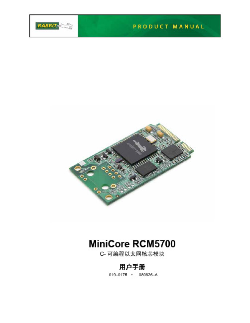
MiniCore RCM5700 用户手册说明书

MiniCore RCM5700 C-可编程以太网核芯模块用户手册019–0176•080826–AMiniCore RCM5700 用户手册零件号 019-0176 • 080826–A • 美国印刷©2008 Digi International Inc. • 版权所有。
在未经 Digi International 明确书面许可的情况下,该手册的任何部分不得以任何形式复制或传播。
只要在副本中保留本版权页,您即有权制作本手册的一本或多本副本。
这些手册副本在未经 Digi International 明确书面许可的情况下不得以任何理由出租或出售。
Digi International 保留不预先通知即对其产品进行修改或改进的权利。
商标Rabbit, MiniCore 及 Dynamic C 都是 Digi International 公司的注册商标。
Wi-Fi 是 Wi-Fi 联盟的注册商标。
Rabbit 5000 及 MiniCore 是 Digi International 公司的商标。
您无需注册即可从 Rabbit 网站免费下载本手册的最新版本。
Digi International 公司MiniCore RCM5700目录第1. 章.简介11.1 RCM5700 的特性 (2)1.2 RCM5700 的优点 (3)1.3 开发和评估工具 (4)1.3.1 RCM5700 标准开发包 (4)1.3.2 RCM5700 豪华开发包 (4)1.3.3 软件 (5)1.3.4 网上文档 (5)第2. 章. 初始使用72.1 安装 Dynamic C (7)2.2 硬件的连接 (8)2.2.1 步骤 1 — 准备好开发用的接口板 (8)2.2.2 步骤 2 — 在接口板上安装模块 (9)2.2.3 步骤 3 — 连接 USB 电缆 (10)2.3 启动 Dynamic C (12)2.4 运行示例程序 (12)2.4.1 故障排查 (12)2.5 然后我应当做什么? (13)2.5.1 技术支持 (13)第3. 章. 运行示例程序153.1 简介 (15)3.2 示例程序 (16)第4. 章. 硬件参考资料214.1 RCM5700 数字输出入接口 (22)4.1.1 存储器输入/输出接口 (28)4.1.2 其他输出入接口 (28)4.2 串行通讯 (29)4.2.1 串行口 (29)4.2.2 以太网 PHY (30)4.2.3 编程口 (30)4.3 编程模式 (31)4.3.1 RCM5700 的单独运行 (32)4.4 其他硬件 (33)4.4.1 时钟倍频 (33)4.4.2 频谱扩展 (33)4.5 存储器 (34)4.5.1 静态随机存储器 (34)4.5.2 闪存 (34)4.5.3 RAM存储器的加密 (34)用户手册第5. 章. 软件参考资料355.1 关于 Dynamic C 的更多内容 (35)5.2 Dynamic C 功能调用 (37)5.2.1 数字输入/输出 (37)5.2.2 串行通讯驱动程序 (37)5.2.3 用户块 (37)5.2.4 RCM5700 的复制 (38)5.2.5 TCP/IP 驱动程序 (38)5.3 升级 Dynamic C (38)5.3.1 添加功能模块 (38)附录 A. RCM5700 规范39A.1 电气和机械特性 (40)A.2 Rabbit 5000 微处理器特性 (44)A.2.1 存储器存取时间 (46)A.3 跨接线的配置 (49)附录 B. 接口板51B.1 简介 (52)B.1.1 接口板特性 (53)B.2 尺寸和布局 (54)B.2.1 电路板连接器 (55)B.3 电源 (56)B.4 使用接口板 (57)B.4.1 添加更多电路板 (58)B.5 接口板跨接线的配置 (59)附录 C. 应用电路开发板61C.1 简介 (62)C.1.1 应用电路开发板特性 (62)C.2 尺寸和布局 (63)C.2.1 电路板连接器 (65)C.3 使用应用电路开发板 (66)C.3.1 添加更多电路板 (67)附录 D. 数字输入/输出附件板69D.1 简介 (70)D.1.1 数字输入/输出附件板特性 (70)D.2 尺寸和布局 (71)D.2.1 电路板连接器 (72)D.3 使用 Digital 输入/输出附件板 (73)D.3.1 配置 (74)D.3.2 添加更多电路板 (76)附录 E. 串行通讯附件板77E.1 简介 (78)E.1.1 串行通讯附件板特性 (78)E.2 尺寸和布局 (79)E.2.1 电路板连接器 (80)E.3 使用串行通讯附件板 (81)E.3.1 配置 (82)E.3.2 添加更多电路板 (84)MiniCore RCM5700附录 F. 使用TCP/IP 特性85F.1 TCP/IP 的连接 (85)F.2 关于 IP 地址的 TCP/IP 入门 (87)F.2.1 IP 地址的解释 (89)F.2.2 如何使用 IP 地址 (90)F.2.3 动态分配互联网地址 (91)F.3 将您的设备置于网络内 (92)F.4 运行 TCP/IP 示例程序 (93)F.4.1 如何设定示例程序内的 IP 地址 (94)F.4.2 如何将计算机设定为直接连接 (95)F.5 运行 PINGME.C 示例程序 (96)F.6 以直接连接方式运行更多示例程序 (97)F.7 然后我应当做什么? (98)附录 G. 电源99G.1 电源 (99)G.1.1 备用电池 (100)G.1.2 备用电池电路 (101)G.1.3 复位脉冲发生器 (101)索引103设计原理图105用户手册MiniCore RCM57001. 简介小型微处理器模块 RCM5700 兼具微型 PCI Express 插卡的外形尺寸和带有 10/100Base-T 以太网功能和 128KB 静态随机存储器的高性能 Rabbit®5000 微处理器。
勃利 Kinetix 5700 训练工站目录说明书

OPERATOR INTERFACE PANEL • 9 illuminated
pushbuttons • 3 illuminated
selector switches • 1 three-position selector
switch
Catalog Number
ABT-TDK5700
Workstation Functionality
Allen-Bradley, CompactLogix, expanding human possibility, Kinetix, Logix 5000 and Studio 5000 Logix Designer are trademarks of Rockwell Automation, Inc. Trademarks not belonging to Rockwell Automation are property of their respective companies.
Unit Dimensions • Width: 24.80 in (62.99 cm) • Height: 20.87 in (53.07 cm) • Depth: 15.23 in (38.68 cm) • Weight: 75 lbs. (34.47 kg) Estimated Lead Time 7 weeks. Some items are available for immediate shipment. Please call for availability. 220-240V Plug Options See the available document on Literature Library for 220-240V Plug Options for Workstations used in EMEA/AP (GMST10-PP524). Related Products The workstation can be used in conjunction with the following products: • Studio 5000 Logix Designer and Logix 5000™ Motion Control Procedures Guide
5700操作手册

第一章ECLIPS-5700 硬件系统第一节系统简介一、ECLIPS 地面系统概述ECIPLS-5700 数控测井地面系统是美国ATLAS 公司90 年代开发生产的新一代测井地面数据采集系统。
该系统采用功能很强的工作站作为主机及高速数据通讯的WTS 遥传系统。
软件以多任务、多用户的UNIX 操作系统为基础,大量采用现代图象处理显示技术。
通过配备阵列化、成像化及大信息量为特点的新一代井下仪器,实现以多参数采集、多任务分时处理为特点的实时测井数据采集、控制和处理。
为客户提供常规和成像测井图件及记录数据,并能完成井壁取心、射孔和测井数据的现场通讯传输及现场测井数据的初步分析处理等服务。
图1.1.1 为ECLIPS-S 型地面系统外观图。
ECLIPS5700 系统通过采用先进的数字数据采集技术和先进的图象显示技术来保证测井数据的质量。
其具有如下特点:1、该系统记录的数据包括仪器的原始信号、经过刻度的工程值和处理后的数据。
由于记录了仪器的原始信号,所以出现刻度误差时可以用不同的参数重新处理测井资料。
2、刻度值和校验值全部都可显示出来,由操作员确认,超差数值会闪亮,引起操作员的注意。
3、可采用多窗口显示核测井仪器所获得的能谱及声波类仪器所获得的波形。
通过用户控制这些窗口既可显示原始数据,也可显示处理过的数据,以便操作员进行实时测井数据的质量控制。
4、可以在主要测井曲线上实时重叠显示重复曲线,以验证曲线的重复性。
5、实时绘制交会图,使操作员可以根据预期的模型验证测井响应的正确性。
6、实时环境校正,以消除测井质量控制过程中操作员的主观评估成分。
7、实时相似校正,以验证声波波形资料的完整性。
8、采用人员安全和数据保护系统。
9、通过采用高端的计算机技术及冗余设计简化数据采集和处理过程,缩短现场工作时间并保证系统的可靠性。
ECLIPS 系统服务平台可用于全部以WTS 方式传输和以传统的电缆遥测传输(3508,3506,3504)的下井仪器。
5700A电压标定仪用户操作手册说明书

E,
3OOk-5OOk
10
1
1
500k-1M
15
1
1
± (ppm output + llV) ± (ppm output llV)rC
10-20
150 + 20
2+ 1
2+1
20-40
80 + 15
2+ 1
2+1
40·20k
12 + 2
2+ 1
2+ 1
220mV
20k-50k
10 + 2
15 + 2
15 + 2
~V
220mV 2.2V l1V 22V 220V
1100V
.3 +.3 .3 + 1 .3 + 2.5 .4 + 5 .5 + 40 .5 + 200
.4 +.1 .3+ .1 .15+ .2 .2 +.4 .3 + 5 .5 + 10
1.5 +.5 1.5 + 2 1 + 1.5 1.5 + 3 1.5 +40 3 +200
Absolute Uncertainty
± 5°C from calibration temperature
雷克萨斯 LX570 汽车 说明书

6速电子控制自动变速系统,为SUV 而生自动变速系统与强大的综合装置协同工作,以适应发动机的高扭矩,再配以精准的齿轮运转,无论 越野或是公路行驶,都将为您带来强劲动力和舒适 体验。
6速电子控制自动变速系统(6 Super ECT) 拥有大范围和密齿比,可以在启动时瞬时加速,在高转速的公路行驶中提供平顺的加速,也能在 低转速的越野行驶中驾驭强劲动力。
领先时代的 降挡控制可在减速时大幅降低油耗,人工智能 变速系统(AI-SHIFT)会根据您的驾驶意图和路况 自动选择变速模式,多模式自动变速系统则让您 享受到手动换挡的运动驾驶乐趣。
5.7升V8发动机,以智能科技激发每一丝潜能杰出的性能表现无畏任何路况条件,宽广的扭矩带能够在2200转速/分钟状态下提供90%的最大扭矩,足以在越野的中低速域爆发出无可匹敌的澎湃动力,更能在 适合公路行驶的高速域持续加速;领先科技DualVVT-i 双智能正时可变气门控制系统, 通过提高进气和排气效率,大幅提高燃烧效率,令5.7升的大排量,同时拥有媲美普通4.0升发动机的燃油经济性;雷克萨斯在减少摩擦损耗方面的不懈努力,让LX570的发动机运转平滑顺畅而且悄无声息。
全时四轮驱动系统(AWD )LX570传动系统采用TORSEN ®防滑差速器LSD*,可以根据路况变化调节 前后轮的扭矩分配。
正常行驶时,系统采用前后比例为40:60的扭矩分配。
在转弯和轮胎打滑时,则优化驱动力并确保良好的牵引力。
圆柱形系统开关 按钮令传动操作异常简便。
*TORSEN ®防滑差速器LSD 为JTEKT 公司注册商标。
汽车稳定控制系统(VSC )感知急转弯或在湿滑路面上转弯时导致的急刹车,并控制车辆的制动力和 驱动力,确保车辆的稳定性。
世界首创四轮主动悬架高度控制系统(AHC)可在高速行驶时自动降低车身高度,确保车身稳定性,提高车辆的空气动力学 性能。
而在L4或低速行驶模式下,则提高车身高度以适应更长的悬架冲程, 在颠簸路况下保持良好的驾驭表现。
高准5700以太网变送器安装手册说明书

安装手册MMI-20035329, Rev AF2023 年 2 月Micro Motion™(高准) 5700 以太网变送器以太网安装安全信息本手册提供的安全信息用于保护人员和设备。
在进行下一步操作前,请仔细阅读每条安全信息。
安全和认证信息如按照本手册中的说明正确安装,则高准产品符合所有适用的欧洲指令。
请参阅 EU 符合性声明,以了解本产品适用了哪些指令。
附带以下文档:针对所有相关欧洲指令的 EU 符合性声明,以及全套 ATEX 安装图纸和说明书。
此外,还可以访问或通过您的当地高准支持中心,获取适用于欧盟以外地区安装的 IECEx 安装说明以及适用于北美地区安装的CSA 安装说明。
符合压力设备指令的设备所附的信息可通过获取。
在欧洲的危险环境安装,如果本国没有相关标准,则可参考标准 EN 60079-14。
其他信息如需获得故障排查信息,请参阅组态手册。
产品样本和手册可从高准网站获取。
退货政策退回设备时必须遵循高准程序。
遵循这些程序可确保符合政府运输机构的法规要求,同时有助于为高准员工提供安全的工作环境。
如不遵守高准规程,高准将不会接受您退回的设备。
有关于返修程序和返修表格,请登录获取,或致电高准客户服务部门获取。
2内容第 章1 开始之前.......................................................................................................................................51.1 关于本手册.....................................................................................................................................51.2 风险说明........................................................................................................................................51.3 相关文档........................................................................................................................................5第 章2 安装准备.......................................................................................................................................72.1 安装检查表.....................................................................................................................................72.2 改装现有安装的其他注意事项.......................................................................................................82.3 电源要求........................................................................................................................................92.4 以太网网络中的 5700 型变送器..................................................................................................10第 章3 安装和传感器接线.......................................................................................................................153.1 一体化安装变送器安装和传感器接线.........................................................................................153.2 安装变送器..................................................................................................................................153.3 分体式变送器与传感器的接线.....................................................................................................183.4 仪表部件接地...............................................................................................................................203.5 旋转传感器上的变送器(可选).................................................................................................223.6 旋转变送器上的用户界面(可选).............................................................................................243.7 旋转远程安装变送器(可选)上的传感器接线盒.......................................................................25第 章4 通道接线.....................................................................................................................................274.1 可用通道......................................................................................................................................274.2 I/O 通道接线................................................................................................................................274.3 以太网通道接线...........................................................................................................................33第 章5 电源接线.....................................................................................................................................375.1 电源接线......................................................................................................................................375.2 使用 M12 端头电缆(可选)进行电源接线................................................................................38第 章6 设置打印机.................................................................................................................................396.1 通过更改打印机默认 IP 地址来设置打印机................................................................................396.2 使用打印机默认 IP 地址来设置打印机........................................................................................406.3 复位接口设置...............................................................................................................................426.4 功能检查失败...............................................................................................................................42第 章7 接通变送器电源..........................................................................................................................43第 章8 设置向导.....................................................................................................................................45第 章9 使用显示控制..............................................................................................................................47第 章10 可用服务端口连接.......................................................................................................................49附录 A 将 5700 连接到 3100 继电器.......................................................................................................51安装手册内容MMI-200353292023 年 2 月安装手册3内容安装手册2023 年 2 月MMI-200353294高准 5700 以太网变送器1 开始之前1.1 关于本手册本手册提供有关高准变送器规划、安装、接线和初始设置的信息。
HP Deskjet 5700 系列 说明书

HP Deskjet 5700 系列
1
7 打印提示....................................................................................................41 打印快捷方式.............................................................................................41 快速/经济打印............................................................................................42 一般打印....................................................................................................42 演示打印....................................................................................................43 灰度打印....................................................................................................43 为打印机设置默认设置..............................................................................43 选择打印质量.............................................................................................44 设置页面顺序.............................................................................................44 在单张纸上打印多页..................................................................................45 打印预览....................................................................................................46 设置自定义纸张尺寸..................................................................................47 选择纸张类型.............................................................................................48 打印任务快速设置......................................................................................49 双面打印....................................................................................................51 调整文档大小 ............................................................................................53 水印...........................................................................................................55
艾默生 5700 变送器 EtherNet IP RSLogix 集成指南说明书

Integration GuideMMI-20029770, Rev AEMarch 2022 Micro Motion™ 5700 TransmittersEtherNet/IP Rockwell RSLogix Integration GuideSafety messagesSafety messages are provided throughout this manual to protect personnel and equipment. Read each safety message carefully before proceeding to the next step.Safety and approval informationThis Micro Motion product complies with all applicable European directives when properly installed in accordance with theinstructions in this manual. Refer to the EU declaration of conformity for directives that apply to this product. The following are available: the EU declaration of conformity, with all applicable European directives, and the complete ATEX Installation Drawings and Instructions. In addition the IECEx Installation Instructions for installations outside of the European Union and the CSAInstallation Instructions for installations in North America are available on the internet at or through your local Micro Motion support center.Information affixed to equipment that complies with the Pressure Equipment Directive, can be found on the internet at. For hazardous installations in Europe, refer to standard EN 60079-14 if national standards do not apply. Other informationFull product specifications can be found in the product data sheet. Troubleshooting information can be found in the configuration manual. Product data sheets and manuals are available from the Micro Motion web site at .Return policyFollow Micro Motion procedures when returning equipment. These procedures ensure legal compliance with governmenttransportation agencies and help provide a safe working environment for Micro Motion employees. Micro Motion will not accept your returned equipment if you fail to follow Micro Motion procedures.Return procedures and forms are available on our web support site at , or by phoning the Micro MotionCustomer Service department.Emerson Flow customer serviceEmail:•Worldwide: ************************•Asia-Pacific: **************************Telephone:2Integration Guide Contents MMI-20029770March 2022 ContentsChapter 1Before you begin (5)1.1 About this document (5)1.2 Related documentation (5)Chapter 25700 transmitters in Ethernet networks (7)2.1 Star topology (7)2.2 Ring topology (8)2.3 Daisy-chain topology (9)Chapter 3Integrate with RSLogix 5000 (11)3.1 Integrate with Rockwell RSLogix 5000 versions 20 and later (11)3.2 Integrate with Rockwell RSLogix 5000 versions 19 and earlier (16)Chapter 4Use explicit (messaging) using the Modbus Object (21)Chapter 5Use explicit (messaging) using the Analog Input Object (25)5.1 Read mass flow value example (25)5.2 Write mass flow example (26)Appendix A Assembly object (04HEX – 16 instances) (27)A.1 Definitions (27)A.2 Class attributes (27)A.3 Input assemblies (27)A.4 Output assemblies (37)A.5 Output Only Heartbeat (instance 253) (40)A.6 Input Only Heartbeat (instance 254) (40)A.7 Listen Only Heartbeat (instance 255) (40)A.8 Usage notes (41)A.9 Common services (41)Appendix B Assembly connections (43)Appendix C Modbus object (44HEX – 1 instance) (45)C.1 Modbus class attributes (45)C.2 Instance attributes (45)C.3 Common services (45)Appendix D Analog Input Point object (0AHEX-51 instances) (49)EtherNet/IP Rockwell RSLogix Integration Guide3Contents Integration Guide March 2022MMI-20029770 4Micro Motion 5700 EtherNet/IP transmittersIntegration Guide Before you begin MMI-20029770March 2022 1 Before you begin1.1 About this documentThis document provides information about how to integrate a Micro Motion 5700 EtherNet/IP transmitter with Rockwell RSLogix 5000.ImportantThis manual assumes that:•The transmitter has been installed correctly and completely according to the instructions in the transmitter installation manual.•Users understand basic transmitter and sensor installation, configuration, and maintenance concepts and procedures.•Users have already set up a Programmable Logic Controller (PLC) project with a working Ethernet network.1.2 Related documentationYou can find all product documentation via the product documentation DVD shipped with the product or at .•Micro Motion 5700 Product Data Sheet•Micro Motion 5700 with Ethernet Transmitters: Installation Manual•Micro Motion 5700 with Ethernet Transmitters: Configuration and Use Manual•Hazardous area installation — see the approval documentation shipped with the transmitter, or download the appropriate documentationEtherNet/IP Rockwell RSLogix Integration Guide5Before you begin Integration Guide March 2022MMI-20029770 6Micro Motion 5700 EtherNet/IP transmitters2 5700 transmitters in Ethernet networksYou can install the 5700 Ethernet transmitter in star, ring, or daisy-chain networks using industrial-rated shielded Ethernet cables.•Make sure that each cable is no longer than 328 ft (100 m).•Connect the 5700 Ethernet transmitter to the host system via a LAN (Local Area Network) and not a WAN (Wide Area Network).•Follow all network security best practices.2.1 Star topology5700 Ethernet transmitters can be installed in a star network.Figure 2-1: 5700 star networkA.Programmable Logic Controller (PLC)B.5700 with Ethernet outputC.External Ethernet switchIntegration Guide 5700 transmitters in Ethernet networksMMI-20029770March 2022EtherNet/IP Rockwell RSLogix Integration Guide 72.2 Ring topology5700 Ethernet transmitters can be installed in a ring network.Figure 2-2: 5700 ring networkA.Programmable Logic Controller (PLC)B.5700 with Ethernet output5700 transmitters in Ethernet networks Integration Guide March 2022MMI-200297708Micro Motion 5700 EtherNet/IP transmitters2.3 Daisy-chain topology5700 Ethernet transmitters can be installed in a daisy-chain network.Figure 2-3: 5700 daisy-chain networkA.Programmable Logic Controller (PLC)B.5700 with Ethernet outputIntegration Guide 5700 transmitters in Ethernet networksMMI-20029770March 2022EtherNet/IP Rockwell RSLogix Integration Guide 95700 transmitters in Ethernet networks Integration Guide March 2022MMI-20029770 10Micro Motion 5700 EtherNet/IP transmitters3 Integrate with RSLogix 50003.1 Integrate with Rockwell RSLogix 5000 versions 20 and laterIf you have Rockwell RSLogix 5000 version 20 or later firmware and programming software, use this section to load the 5700 Electronic Data Sheet (EDS) and commission the device using the RSLogix 5000 programming package.PrerequisitesIf you are upgrading the EDS from an older version, unregister the old EDS first using the RSLogix 5000 EDS Hardware Installation Tool at Tools→EDS Hardware Installation Tool.Procedure1.Download the EDS file using one of the following methods:From the transmitter display, choose Menu→USB Options→TransmitterDownload Support Files→EDS file.Follow the menu to copy the EDS file to the memory drive.Copy the zip file from the USB memory drive to the PC where RSLogix 5000 isUnzip the file to a chosen location.In RSLogix 5000, choose Tools→EDS Hardware Installation Tool and register the2.To add the 5700 Ethernet device to the RSLogix 5000 Ethernet network, right-click the Ethernetnetwork and select New Module…Examplea)Select the 5700 from the Select Module Type window and press Create.ExampleThe New Module properties dialog is displayed. The EDS generates an Add On Profile (AOP) for the 5700 that loads all the variables into the controller's input and output image tables as named variables with the correct data types.b)Enter the Name of the module.c)Enter the IP Address.3.Change or keep the current connection type.4.From the General tab, change the connection type:a)Select the Change… button.Exampleb)Click the current connection.Default = Mass Flow In & BasicA pull-down menu with all the available connection types is displayed. For descriptions, seeTable B-2.c)Select your appropriate connection, and press OK.NoteIf you change the connection after the device goes online, you will need to take the controller offline in order for the change to take effect.5.On the New Module properties dialog, click OK.6.On the Select Module Type dialog, click Close.7.Open Controller Tags to verify the organization of data.3.2 Integrate with Rockwell RSLogix 5000 versions 19 and earlierUse this section if you have Rockwell RSLogix 5000 version 19 or earlier firmware and programming software. These early versions do not support the transmitter Electronic Data Sheet (EDS)-generated Add On Profile (AOP). Instead, you must use the generic module hardware tree.Procedure1.Download the EDS file using one of the following methods:From the transmitter display, choose Menu→USB Options→TransmitterDownload Support Files→EDS file.Follow the menu to copy the EDS file to the memory drive.Copy the zip file from the USB memory drive to the PC where RSLogix 5000 isUnzip the file to a chosen location.Download the EDS from the Micro Motion 5700 Ethernet product website.Unzip the file to a chosen location.2.In RSLogix 5000, choose Tools→EDS Hardware Installation Tool and register the 5700 EDS file.3.To add the 5700 Ethernet device to the RSLogix 5000 Ethernet network, right-click the Ethernetnetwork and select New Module....4.From the By Vendor tab, select ETHERNET-MODULE Generic Ethernet Module.Example5.Select OK.6.Select Data-DINT as the module data type.7.Select the appropriate assembly instances for your application.Enter the assembly numbers in the generic module setup, along with the data sizes that are listed in Table B-1.Examplea.Input = 101b.Output = 150c.Configuration = 1NoteThe 5700 does not use a Configuration instance. Enter 1 in the Assembly Instance column, and0 length for the Size column.8.Enter the IP Address of the transmitter.9.Press OK.10.Open Controller Tags to see the data organization.e your preferred programming techniques to convert the data from the input and output imagetables to the correct data types.•The transmitter process variables are generally type REAL, use the COP command to convert them.•The byte ordering is correct, so no byte swapping is needed.Example4 Use explicit (messaging) using the Modbus ObjectThe programming for explicit variables is the same regardless of the controller firmware version. Explicit messaging differs from implicit messaging in that the service code and class refer to a Modbus data type rather than a specific data item. The message source element provides the location of the desired data in the transmitter's database. The only difference is that the Common Industrial Protocol (CIP) message type refers to a type of data in the transmitter's internal database rather than a specific data item. The desired data item is referenced as the Modbus address in the CIP message. The data item does not have to be part of an assembly, so in the example in Figure 4-1, a batcher data item is requested to be read.For more information about CIP message codes, see Modbus object (44HEX – 1 instance).Procedure1.Create the Msg and select it.2.Select the Source Element that was previously created as a controller scope tag.Figure 4-1: Batch status messageExampleThe following example shows a message that writes data to the transmitter database.The Automatic Overshoot Compensation (AOC) value is a floating point number that you will need to convert to integer format using a COP command prior to referencing it in the Source Element of the message.Integration Guide Use explicit (messaging) using the Modbus ObjectMMI-20029770March 2022Combine the AOC value with the transmitter database (Modbus) address and length to form the message's source element. This can be an array as shown in the following graphic or a user-defined data type (UDT). The first element is the Modbus address (zero based), the second is the length, andfinally the data in integer (INT) format.The address and data length will be returned if the write is successful. For example, Set_AOC_Rtn.Use explicit (messaging) using the Modbus Object Integration Guide March 2022MMI-20029770Integration Guide Use explicit (messaging) using the Modbus Object MMI-20029770March 2022Use explicit (messaging) using the Modbus Object Integration Guide March 2022MMI-200297705 Use explicit (messaging) using the Analog Input ObjectAs described in the previous chapter, explicit messaging using the Modbus object gives the programmer access to all the data available in the transmitter database. A simpler method than using the Modbus object to access process variable values, engineering units, and status, is to use the standard Common Industrial Protocol (CIP) Analog Input object.Related informationAnalog Input Point object (0AHEX-51 instances)5.1 Read mass flow value exampleThe following example shows a message that reads the mass flow value using the mass flow instance of the Analog Input class.Procedure1.Create the Msg and select it.2.Enter A in the Class field.The A comes from the Analog Input object class 0xA.e Analog Input Point object (0A HEX -51 instances) as a reference for the following steps:a)Enter the appropriate instance in the Instance field as a hexadecimal number.In this example, Mass Flow is Instance 1.b)Enter the appropriate attribute in the Attribute field as a hexadecimal number.In this example, the value parameter is Attribute 3.Integration Guide Use explicit (messaging) using the Analog Input ObjectMMI-20029770March 20225.2 Write mass flow exampleThe following example shows a message that writes the mass flow units using the mass flow instance of the Analog Input class.Procedure1.Create the Msg and select it.2.Enter A in the Class field.The A comes from the Analog Input object class 0xA.e Analog Input Point object (0A HEX -51 instances) as a reference for the following steps:a)Enter the appropriate instance in the Instance field as a hexadecimal number.In this example, Mass Flow is Instance 1.b)Enter the appropriate attribute in the Attribute field as a hexadecimal number.In this example, the engineering units parameter is Attribute 100 (64 Hex).Use explicit (messaging) using the Analog Input Object Integration Guide March 2022MMI-20029770Integration Guide Assembly object (04HEX – 16 instances) MMI-20029770March 2022 A Assembly object (04HEX – 16 instances)A.1 DefinitionsA.2 Class attributesClass attributes (instance 0)A.3 Input assembliesTable A-1: Input instance attributes (Instances 100-112)Table A-2: Common input dataAssembly object (04HEX – 16 instances)Integration Guide March 2022MMI-20029770Integration Guide Assembly object (04HEX – 16 instances) MMI-20029770March 2022Table A-3: Liquid volume flowAssembly object (04HEX – 16 instances)Integration Guide March 2022MMI-20029770 Table A-4: Gas volume flowTable A-5: API referralTable A-6: Concentration measurementTable A-7: BatcherTable A-8: Small input configurable data setTable A-9: Medium input configurable data setTable A-10: Large input configurable data setTable A-11: Advanced Phase Measurement (APM) – liquidTable A-12: Advanced Phase Measurement (APM) – gas volume(1)Do not include the parenthesis in the label. Table A-13: Wet Gas MeasurementTable A-14: Device StatusA.4 Output assembliesTable A-15: Common output data — Discrete actions onlyNoteCommon output data is required for every output assembly in order to access 5700 functions. Depending on the application, not all functions may be used.Table A-16: External process dataTable A-17: BatcherTable A-18: Batcher and external process dataTable A-19: Output configurable dataTable A-20: Advanced Phase Measurement (APM)A.5 Output Only Heartbeat (instance 253)Use of this instance number in place of an input assembly instance number allows I/O connections to only write data to the transmitter without any input data returned.If not practical, remove this instance.A.6 Input Only Heartbeat (instance 254)Use of this instance number in place of an output assembly instance number allows I/O connections to monitor the input data from the transmitter without providing any output data, called an “input only”connection. Conceptually, input-only connections are used when HMIs or monitoring systems need to track input data, while still allowing a Programmable Logic Controller (PLC) to provide the control side, or write the outputs.This connection type is required per the Recommended Functionality for EtherNet/IP Devices document.For more information about Input Only connections, see Volume 1 of the ODVA Specification (Common Industrial Protocol).A.7 Listen Only Heartbeat (instance 255)Much like Input Only connections, Listen Only connections use this instance number in place of an output assembly instance number to open an I/O connection. The I/O connection monitors the input data from theIntegration Guide Assembly object (04HEX – 16 instances) MMI-20029770March 2022 transmitter. Existing I/O connections have dependencies for allocation and timeouts that are different than Input Only connections.A.8 Usage notesAll output assemblies contain a common data as outlined in assembly instance 150. To maintain proper ownership of the output data (no toggling of outputs between multiple sources), only a single output assembly may be selected for use in I/O messaging. To achieve this, there is an output lock in place to mark all output assemblies as “owned” even though only a single assembly is actually in use.All input instances can properly co-exist since no ownership is required. While not practical for most applications, multiple PLCs can theoretically open Input Only connections to any or all of the input assembly instances, up to the maximum number of I/O connections supported.A.9 Common servicesAssembly object (04HEX – 16 instances)Integration Guide March 2022MMI-20029770Integration Guide Assembly connections MMI-20029770March 2022 B Assembly connectionsTable B-1: Input and output assembliesTable B-2: Connection typesAssembly connections Integration Guide March 2022MMI-20029770Integration Guide Modbus object (44HEX – 1 instance) MMI-20029770March 2022 C Modbus object (44HEX – 1 instance)The Modbus object provides a “pass through” to the internal Modbus representation of any data point. All validation related to addressing, length, or write validation is handled by the Modbus DLL.C.1 Modbus class attributesC.2 Instance attributesNo instance attributes are defined.C.3 Common services4B HEX Read_Discrete_Inputs (Modbus FC 0x02)Table C-1: Request formatTable C-2: Response formatModbus object (44HEX – 1 instance)Integration Guide March 2022MMI-200297704C HEX Read_Coils (Modbus FC 0x01)Table C-3: Request formatTable C-4: Response format4D HEX Read_Input_Registers (Modbus FC 0x04)Table C-5: Request formatTable C-6: Response format4E HEX Read_Holding_Registers (Modbus FC 0x03)Table C-7: Request formatTable C-8: Response formatIntegration Guide Modbus object (44HEX – 1 instance) MMI-20029770March 20224F HEX Write_Coils (Modbus FC 0x0F)Table C-9: Request formatTable C-10: Response format50HEX Write_Holding_Registers (Modbus FC 0x10)Table C-11: Request formatTable C-12: Response formatModbus object (44HEX – 1 instance)Integration Guide March 2022MMI-20029770D Analog Input Point object (0A HEX -51instances)Table D-1: AttributesTable D-2: ServicesTable D-3: InstancesIntegration Guide Analog Input Point object (0A HEX -51 instances)MMI-20029770March 2022Analog Input Point object (0A HEX-51 instances)Integration Guide March 2022MMI-20029770。
天宝Trimble_5700用户指南

Trimble 5700 user guide 一、基本说明图示四个基本面板前控制面板后面板底面板顶接口面板顶面板接口功能两种移动安装静态测量量取天线高与手机相连二、基本操作1 谨慎操作:勿在电脑上格式化CF卡,应在接收机里格式化之——置卡于接收机内,长按电源按钮30秒。
2 前面板操作:前面板按钮与指示灯⑴开、关接收机:按下电源按钮,接收机处于“开”状态,按住电源按钮,2秒钟后LED灯全熄灭,放开按钮,接收机被关闭。
按下记录按钮,开始记录;按下记录按钮2秒钟,记录灯熄灭,停止记录。
⑵黄色的LED记录指示灯的几种状态:正常闪烁为每3秒闪一次。
开:数据被存入;慢闪:足够的静态数据被存入。
如果红色的SV Tracking LED长亮,并且其它LED 不亮,表明接收机处于监视模式,关闭电源并重开,即进入正常操作状态。
快闪:数据被存入,但内在较少。
更慢闪:接收机处于休眠模式,定时应用文件开始前5分钟将唤醒接收机。
关:数据没记录。
⑶红色卫星跟踪LED指示灯的几种状态:正常闪烁为每3秒闪一次。
慢闪:索定4颗以上卫星;快闪:索定3颗以下卫星;关:无索定卫星;开:接收机处于监视状态,正在检查新固件并安装。
⑷绿色LED无线电指示灯:慢闪:收到一个数据包或事件标识。
⑸LED电池灯的状态如下表:⑸两种数据格式:*.t01含有GLONASS数据,*.dat只含有GPS数据,Trimble Business Center支持*.t01,而Trimble Geometic Office只支持*.dat。
三、数据传输接收机中的CF卡可容纳500多个文件,卡中文件必须为8.3格式,不支持文件扩展名。
数据传输可用的软件:Trimble Business Center software(*.t01), Trimble Data Transfer utility(*.dat).也可把CF卡直接从接收机取出装入电脑拷贝。
数据类型及传输软件:Trimble Geomatics Office不支持*.t01,因而,用TGO解算之前,必须将数据从*.t01转为*.dat,但转换后GLONASS数据随之丢失。
N5700快速参考指南

GPIB 地址:按住 OCP/488 时,可选择 GPIB 地址。
2 – CV(恒压)指示灯
亮起时,表示设备正在恒压模式下工作 - 输出电压保持恒定。
3 – DC VOLTS(直流电压) 显示屏
4 – DC AMPS(直流电流) 显示屏
LED 显示屏,通常显示在感测端子上测得的电压 。按下 LIMIT 时,该 显示屏将显示已设定的电压设置。按住 OVP/UVL 时,该显示屏将显示 OVP 或 UVL 设置。按住 OCP/488 时,该显示屏将显示 GPIB 地址。按 住 LAN 时,该显示屏将显示 IP 和以太网地址。 LED 显示屏,通常显示在输出端子处测得的电流 。按下 LIMIT 时,该 显示屏将显示已设定的电流设置。按住 LAN 时,该显示屏将显示 IP 和以太网地址。
Agilent N5700 直流电源概览 4 前面板概览 6 后面板概览 8 安装设备 11 连接电源线 12 连接负载(6V 到 60V 设备) 14 连接负载(80V 到 600V 设备) 15 输出电压感测 16 负载注意事项 17 并联连接 18 串行连接 20 一般工作方式 21 保护功能 22 输出开/关控制按钮 23 输出电压和电流的模拟编程 25 配置和使用远程接口 27
根据美国和国际版权法,未经安捷伦科技公司事先同意和书面许可,本 文档的任何部分不得影印、复制或翻译成其他语言。
本文档所含资料“按原样”提供,在以后的版本中如有修改,恕不另行 通知。此外,在适用的法律所允许的最大范围内,安捷伦对与此手册相 关的内容及其中所含的信息不作任何明示或默示的保证,包括但不限于 为特定目的的适销性和适用性所作的默示保证。对其中包含的错误或由 供给、使用本文档或由本资料的适用性而引起的偶然或继发的损失,安 捷伦不承担任何责任。如果在安捷伦和用户单独签订的书面协议中有关 此文档资料的保证条款与此处的条款发生冲突,则以单独签订协议中的 保证条款为准。
