安装说明
HP打印机安装指南说明书

使用入门1. 请按照设置手册页上的说明设置打印机。
2. 请访问 12 安装移动应用或 HP 打印机软件并将打印机 连接至您的网络。
对于 Windows® 用户,如果您的计算机未连接到 Internet ,请将打印机软件 CD 插入到您的计算机中。
如果 安装程序没有启动,请浏览至“计算机”,双击带 HP 徽标的 CD/DVD 驱动器图标,然后双击 setup.exe 。
3. 在线创建账户以激活您的打印机。
安装移动应用或打印机软件后,将全程指导您创建账户。
了解更多信息电子版帮助:安装软件期间,通过从推荐的软件中选择电子版帮助来安装帮助文件。
打印、疑难排解和支持的信息;除此之外,还有通告、环境和管制信息,自述文件:该自述文件包含有关系统要求的信息和有关设置和使用打印机的更新信息。
将 HP 打印机软件 CD 插入到您的计算机中,然后双击 ReadMe.chm (Windows) 或打开“文档”文件夹 (OS X)。
在 Web 上:其他帮助和信息:/go/support 。
打印机注册: 。
一致性声明: www.hp.eu/certificates 。
此处包含的信息如有更改恕不另行通知。
*G3J47-90013**G3J47-90013*G3J47-90013Windows® 8.1单击“开始”屏幕左下角的向下箭头,选择打印机名称,单击帮助,然后选择 搜索 HP 帮助。
Windows® 8在“开始”屏幕上,右键单击屏幕上的空白区域,单击应用程序栏中的所有 应用程序,选择打印机名称,然后选择帮助,再选择搜索 HP 帮助。
Windows® 7Windows Vista®Windows XP®单击开始,选择程序或所有程序,然后依次选择 HP 、打印机名称和帮助。
OS X v10.10 Yosemite OS X v10.9 Mavericks OS X v10.8 Mountain Lion在查找程序中,选择帮助菜单中的帮助中心。
使用说明和安装说明说明书

R e g i s t e ry o u rn e w d e v i c eo nM y B o s c h no w a n dg e t f r e e b en e f i t s:b o sc h-h o me.c o m/w e l c o m e Warming drawerBIC510N.0W BID510N.0W[en]User manual and installation instructions2 [zh]使用说明和安装说明11en Safety2Table of contentsINFORMATION FOR USE 1Safety.................................................................... 22Preventing material damage ............................... 33Environmental protection and saving en-ergy....................................................................... 34Familiarising yourself with your appliance........ 45Before using for the first time............................. 46Tableware............................................................. 47Basic operation.................................................... 58Preheating tableware........................................... 59Keeping food warm.............................................. 510Cleaning and servicing........................................ 611Troubleshooting................................................... 612How it works......................................................... 713Customer Service. (814)INSTALLATION INSTRUCTIONS (8)14.4Safe installation ...................................................91 SafetyObserve the following safety instructions.1.1 General information¡Read this instruction manual carefully.¡Keep the instruction manual and the product information safe for future refer-ence or for the next owner.¡Do not connect the appliance if it has been damaged in transit.1.2 Intended useThis appliance is designed only to be built into kitchen units. Read the special installation instructions.Only a licensed professional may connect ap-pliances without plugs. Damage caused by in-correct connection is not covered under the warranty.Only use this appliance:¡To keep food warm and to warm cookware.¡In private households and in enclosed spaces in a domestic environment.¡Up to an altitude of max. 4000 m abovesea level.Do not use the appliance:¡On boats or in vehicles.¡with an external timer or a remote control.1.3 Restriction on user groupThis appliance may be used by children aged 8 or over and by people who have reduced physical, sensory or mental abilities or inad-equate experience and/or knowledge,provided that they are supervised or have been instructed on how to use the appliance safely and have understood the resulting dangers.Do not let children play with the appliance.Children must not perform cleaning or user maintenance unless they are at least 15 years old and are being supervised.Keep children under the age of 8 years away from the appliance and power cable.1.4 Safe useWARNING ‒ Risk of fire!The inside of the appliance gets very hot and may cause flammable materials to ignite.▶Never place flammable objects or plasticcontainers in the appliance.WARNING ‒ Risk of burns!The accessories and cookware become very hot during operation.▶Always use oven gloves when removing hot accessories or cookware from the ap-pliance.The inside of the appliance becomes very hot during operation.▶Never touch the inside of the appliance while it is hot.▶Keep children away from the appliance.The appliance becomes hot during operation.▶Allow the appliance to cool down beforecleaning.WARNING ‒ Risk of electric shock!Incorrect repairs are dangerous.▶Repairs to the appliance should only be carried out by trained specialist staff.▶Only use genuine spare parts when repair-ing the appliance.▶If the power cord of this appliance is dam-aged, it must be replaced by trained spe-cialist staff.Preventing material damage en3If the insulation of the power cord is dam-aged, this is dangerous.▶Never let the power cord come into contact with hot appliance parts or heat sources.▶Never let the power cord come into contact with sharp points or edges.▶Never kink, crush or modify the power cord.An ingress of moisture can cause an electric shock.▶Do not use steam- or high-pressure clean-ers to clean the appliance.If the appliance or the power cord is dam-aged, this is dangerous.▶Never operate a damaged appliance.▶Never pull on the power cord to unplug the appliance. Always unplug the appliance at the mains.▶If the appliance or the power cord is dam-aged, immediately unplug the power cord or switch off the fuse in the fuse box.▶Call customer services. →Page 8WARNING ‒ Risk of suffocation!Children may put packaging material over their heads or wrap themselves up in it and suffocate.▶Keep packaging material away from chil-dren.▶Do not let children play with packaging ma-terial.Children may breathe in or swallow small parts, causing them to suffocate.▶Keep small parts away from children.▶Do not let children play with small parts.2 Preventing material damageATTENTION!Excessive weight may damage the appliance.▶The appliance has a maximum load capacity of 15 kg.Moisture may damage the appliance.▶Do not use the appliance to store food and drinks.The humidity of the food may cause corrosion dam-age.3 Environmental protection and saving energy3.1 Disposing of packagingThe packaging materials are environmentally compat-ible and can be recycled.▶Sort the individual components by type and dispose of them separately.en Familiarising yourself with your appliance44 Familiarising yourself with your appliance4.1 ApplianceYou can find an overview of the parts of your appliance here.4.2 ControlsYou can use the control panel to configure all functions of your appliance and to obtain information about the 5 Before using for the first timeConfigure the settings for initial start-up. Clean the ap-pliance and accessories.5.1 Cleaning and heating up the appliance before using it for the first time1.Clean the appliance.2.Remove the accessories.3.Heat up the appliance at 80 °C for one hour.a Smoke development and odour development arenormal.6 TablewareThese instructions help you to avoid damaging your tableware.6.1 Suitable tablewareThe warming drawer has a maximum load capacity of 15 kg. You can use it to preheat the place settings for 6 or 12 people, for example.Drawer – 14 cm Drawer – 29 cm 6 dinner plates 24 cm diameter 12 dinner plates 24 cm diameter 6 soup bowls 10 cm diameter 12 soup bowls 10 cm diameter 1 bowl 19 cm diameter 1 bowl 22 cm diameter 1 bowl17 cm diameter 1 bowl 19 cm diameter 1 meat platter32 cm1 bowl17 cm diameter 2 meat platters32 cmBasic operation en57 Basic operation7.1 Opening the appliance▶Press on the centre of the warming drawer.a The warming drawer pops open and can be pulledout.7.2 Closing the appliance▶Press on the centre of the warming drawer andpush it back in.7.3 Switching on the appliance▶Press .7.4 Switching off the appliance▶Press .7.5 Setting the temperature▶Set the temperature to any value between , and .8 Preheating tablewareFood does not cool down as quickly on preheated tableware. Drinks also remain warm for longer.8.1 Starting the "Preheat tableware"functionWARNING ‒ Risk of burns!Drinking vessels become very hot at high temperat-ures.▶For drinking vessels, set the settings to .1.Place an anti-slip mat at the bottom of the drawer toprevent the tableware scratching the interior surface of the drawer.2.Place the tableware in the warming drawer.‒Distribute the tableware across the entire bottom of the warming drawer to reduce the preheating time.Do not block the ventilation opening with tall items of tableware or stacks of plates. Keeping the ventila-tion opening clear ensures that hot air can circulate efficiently.3.Turn the temperature selector to set the required temperature.A setting of up to is suitable for tableware. For drinking vessels, the settings from to are suit-able.4.Switch on the appliance.a The operation indicator lights up, the applianceheats up and the fan runs.5.Close the warming drawer.Note: The preheating time depends on the material,thickness, quantity and distribution of the tableware.For place settings for 6 people, the preheating time is approx. 15-25 minutes.8.2 Ending the "Preheat cookware" functionWARNING ‒ Risk of burns!The accessories and/or cookware become very hot during operation.▶Always use oven gloves to remove accessories or cookware from the cooking compartment.1.Open the warming drawer.2.Switch off the appliance.3.Remove the cookware.9 Keeping food warmYou can use the warming drawer to keep food warm for a certain period of time.We advise against keeping food warm for longer than an hour. Suitable food includes meat, poultry, fish,sauces, vegetables, side dishes and soups.9.1 Starting the "Keep food warm" functionATTENTION!Hot cookware from the hob damages the anti-slip mat in the warming drawer.▶Never take hot pots and pans off the hob and place them directly on the anti-slip mat.1.Place an anti-slip mat at the bottom of the drawer toprevent the tableware scratching the interior surface of the drawer.The anti-slip mat is food-safe. Dry food can be heated directly on the anti-slip mat in the warming drawer. The anti-slip mat must then be cleaned.2.Place the tableware in the warming drawer.3.Turn the temperature selector to set the required temperature.4.Switch on the appliance.a The operation indicator lights up, the appliance heats up and the fan runs.5.Preheat the tableware for approx. 10 minutes.6.Place food into the preheated tableware.‒Do not completely fill the tableware with food to prevent any content from spilling out when you open and close the warming drawer.‒Cover food which dries out easily with a heat-res-istant lid or aluminium foil.7.Close the warming drawer.en Cleaning and servicing69.2 Ending the "Keep food warm" functionWARNING ‒ Risk of burns!The accessories and/or cookware become very hot during operation.▶Always use oven gloves to remove accessories or cookware from the cooking compartment.1.Open the warming drawer.2.Switch off the appliance.3.Remove the cookware.10 Cleaning and servicingTo keep your appliance working efficiently for a long time, it is important to clean and maintain it carefully.10.1 Cleaning productsYou can obtain suitable cleaning products from after-sales service or the online shop.ATTENTION!Unsuitable cleaning products may damage the sur-faces of the appliance.▶Do not use harsh or abrasive detergents.▶Do not use cleaning products with a high alcohol content.▶Do not use hard scouring pads or cleaning sponges.▶Only use glass cleaners, glass scrapers or stainless steel care products if recommended in the cleaning instructions for the relevant part.▶Wash sponge cloths thoroughly before use.10.2 Cleaning the applianceWARNING ‒ Risk of electric shock!An ingress of moisture can cause an electric shock.▶Do not use steam- or high-pressure cleaners toclean the appliance.WARNING ‒ Risk of burns!The appliance becomes hot during operation.▶Allow the appliance to cool down before cleaning.Requirement: The appliance is switched off.1.Clean the appliance with a damp cloth and a neutral cleaning agent, such as washing-up liquid and wa-ter.2.Dry with a soft cloth.10.3 Cleaning the stainless steel surfaces1.Always remove limescale, grease, starch or albuminstains immediately.Corrosion may form under such stains.2.Clean with water and some washing-up liquid.3.Dry with a soft cloth.10.4 Cleaning the glass front▶Clean the glass front using a glass cleaning productand a soft cloth.‒Do not use any abrasive sponges that may scratch or any glass scrapers.10.5 Cleaning the anti-slip mat1.Remove the anti-slip mat to clean it.2.Clean the anti-slip mat with washing-up liquid.11 TroubleshootingYou can rectify minor faults on your appliance yourself.Read the troubleshooting information before contactingafter-sales service. This will avoid unnecessary costs.WARNING ‒ Risk of injury!Improper repairs are dangerous.▶Repairs to the appliance should only be carried out by trained specialist staff.▶If the appliance is defective, call Customer Service.WARNING ‒ Risk of electric shock!Incorrect repairs are dangerous.▶Repairs to the appliance should only be carried out by trained specialist staff.▶Only use genuine spare parts when repairing the appliance.▶If the power cord of this appliance is damaged, it must be replaced by trained specialist staff.11.1 MalfunctionsFaultCause and troubleshooting The cookware or food is not heating up.There has been a power cut.▶Check whether the lighting in your kitchen or other appliances are working.The appliance is switched off.▶Switch the appliance on.The warming drawer is not completely closed.▶Close the warming drawer.How it works en7FaultCause and troubleshooting The appliance is not working.The circuit breaker is faulty.▶Check the circuit breaker in the fuse box.The cookware or food does not get warm enough.The cookware or food has not been heated for long enough.▶Heat the cookware or the food for a longer period of time.The warming drawer is not completely closed.▶Close the warming drawer.The warming drawer was open for a long time.▶Close the warming drawer.The warming drawer was not adequately preheated.▶Preheat the warming drawer sufficiently.The ventilation opening has been blocked by tableware.▶Remove tall tableware from the ventilation opening.The operation indic-ator light does not light up.The operation indicator light is defective.▶Call the after-sales service. → "Customer Service", Page 8The fuse in the fuse box has blown.The circuit breaker is faulty.▶Pull out the mains plug.▶Call the after-sales service. → "Customer Service", Page 812 How it worksHere, you can find the ideal settings for various dishes as well as the best accessories and cookware. We have tailored these recommendations to your appliance.12.1 Recommended settingsThe following settings have been specially tested for your appliance.Tableware and drinking vessels DishPreheating thePreheating tableware Level InformationDefrosting frozen foods DishPreheating the Preheating tableware LevelInformationen Customer Service 8Warming DishPreheating thePreheating tableware Level InformationmuffinsKeeping warm DishPreheating the Preheating tablewareLevel InformationMelting DishPreheating the Preheating tableware LevelInformationProving dough Dish Preheating thePreheating tableware Level Information trays13 Customer ServiceDetailed information on the warranty period and terms of warranty in your country is available from our after-sales service, your retailer or on our website.If you contact Customer Service, you will require the product number (E-Nr.) and the production number (FD) of your appliance.The contact details for Customer Service can be found in the enclosed Customer Service directory or on our website.13.1 Product number (E-Nr.) and production number (FD)You can find the product number (E-Nr.) and the pro-duction number (FD) on the appliance's rating plate.You can see the rating plate with these numbers when you open the drawer.Make a note of your appliance's details and the Cus-tomer Service telephone number to find them again quickly.14 Installation instructionsObserve this information when installing the appliance.Installation instructions en914.1 Included with the applianceAfter unpacking all parts, check for any transport dam-age and for completeness of delivery.14 cm29 cm14.2 Installation in the cabinetYou will find the dimensions of the appliance here14 cm29 cm14.3 Instructions for the electrical connectionIn order to safely connect the appliance to the elec-trical system, follow these instructions.¡The appliance must only be connected to a protect-ive contact socket that has been correctly installed.Only a qualified electrician may install a socket or replace the connecting cable, taking the appropriate regulations into account.¡The appliance must only be connected with the power cable provided. Connect the power cable to the back of the appliance.¡Connecting cables with various plug types are avail-able from after-sales service.¡No multi-plugs, multiple connectors or extension leads must be used. Overloading causes a risk of fire.¡If the plug can no longer be reached after the in-stallation, a partition must be provided in the phases in the permanent electrical installation in accord-ance with the installation regulations.Follow these safety instructions when in-stalling the appliance.WARNING ‒ Risk of suffocation!Children may put packaging material over their heads or wrap themselves up in it and suffocate.▶Keep packaging material away from chil-dren.▶Do not let children play with packaging ma-terial.WARNING ‒ Risk of electric shock!If the insulation of the power cord is dam-aged, this is dangerous.▶Never let the power cord come into contact with hot appliance parts or heat sources.▶Never let the power cord come into contact with sharp points or edges.▶Never kink, crush or modify the power cord.en Installation instructions10WARNING ‒ Risk of injury!Sharp-edged parts may be accessible during installation.▶Wear protective gloves.14.5 InstallationFitted unitsThis is where you can find information about safe in-stallation.ATTENTION!Covering the ventilation slots and air intake openings causes the appliance to overheat.▶Do not cover ventilation slots and air intake open-ings.If the appliance is installed behind a decorative panel,this may cause it to overheat.▶Do not install the appliance behind a decorative panel.The built-in unit must not have a rear panel behind the appliance.The minimum distance between the wall and the cab-inet base or back wall of the cabinet that is situated above must be complied with.Observe the installation instructions for the appliance installed above.If no intermediate floor is possible above the appliance or above the oven, install tilt protection for the appli-ance. Suitable tilt protection can be obtained from cus-tomer service, on our website or in the online shop.Installing the applianceWARNING ‒ Risk of electric shock!If the insulation of the power cord is damaged, this is dangerous.▶Never let the power cord come into contact with hot appliance parts or heat sources.▶Never let the power cord come into contact with sharp points or edges.▶Never kink, crush or modify the power cord.WARNING ‒ Risk of injury!After removing the transport lock, the drawer may open suddenly during transport.▶Transport the appliance in such a way that the drawer does not accidentally open.The high weight of the appliance may result in injury when lifted.▶Do not lift the appliance on your own.1.Insert the power cord into a protective contactsocket.The power cord must not touch the rear and base of the appliance after installation.2.Insert the appliance.3.Centre the appliance.4.5.Remove and dispose of the protective padding.安全性 zh 11目录使用说明书1安全性 (11)2避免财产损失 (12)3环境保护和节约 (12)4了解机器 (12)5首次使用前 (12)6餐具 (13)7操作基本知识 (13)8预热餐具 (13)9食物保温 (13)10清洁和保养 (14)11处理故障 (14)12工作原理 (15)13客户服务 (16)14安装说明书 (16)14.4安全安装..............................................................171 安全性请注意以下安全注意事项。
软件安装说明书
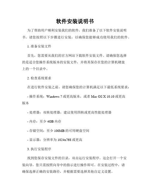
软件安装说明书为了帮助用户顺利安装我们的软件,我们准备了以下软件安装说明书。
请您按照以下步骤进行安装,以确保您能够成功使用我们的软件。
1. 准备安装文件首先,您需要从我们的官方网站下载软件安装文件。
请确保您选择的是适合您操作系统版本的安装文件,并将其保存在您的计算机硬盘上的一个目录中。
2. 检查系统要求在进行软件安装之前,请您确保您的计算机满足以下最低系统要求:- 操作系统:Windows 7或更高版本,或者Mac OS X 10.10或更高版本- 处理器:双核处理器,建议使用四核或更高性能处理器- 内存:至少4GB内存- 存储空间:至少100MB的可用硬盘空间- 显示器:分辨率为1024x768或更高3. 执行安装程序找到您保存安装文件的目录,双击运行安装程序。
这会打开一个安装向导,您只需按照向导中的指示进行操作即可。
在安装过程中,请确保选择正确的安装路径,并根据需要选择其他自定义设置。
4. 阅读许可协议在安装过程中,您将看到软件使用许可协议。
请仔细阅读所有条款和条件,并在同意之前确保您理解其中的内容。
如果您不同意协议的任何条款,请不要继续安装软件。
5. 等待安装完成一旦您点击了“同意”或“安装”按钮,安装程序将开始复制文件并配置软件。
请耐心等待直到安装完成。
这可能需要一些时间,取决于您的计算机性能和文件大小。
6. 快捷方式创建安装程序将询问您是否要在桌面上创建软件的快捷方式。
如果您想要快速访问软件,您可以选择创建快捷方式。
否则,您可以选择不创建。
7. 完成安装一旦安装完成,您将看到一个安装成功的提示。
点击“完成”按钮关闭安装程序。
8. 启动软件现在,您可以通过双击桌面上的快捷方式或者从“开始”菜单中找到软件并点击打开。
软件将启动并显示欢迎界面。
9. 激活软件有些软件可能需要激活才能正常使用。
请确保您按照软件提供的激活指南进行操作。
通常,您需要输入许可证密钥或注册邮箱,并遵循指示完成激活过程。
设备安装说明
设备安装说明合同书甲方:地址:联系人:联系电话:乙方:地址:联系人:联系电话:鉴于甲方需要安装设备,为确保安装工作的顺利进行,甲方与乙方达成以下协议:一、安装内容1.1 甲方将提供具体设备的名称、型号及数量,并提供设备安装所需的技术规范和操作手册。
1.2 乙方将根据甲方提供的技术规范和操作手册,按照规范和要求进行设备安装。
二、工作时间与地点2.1 安装工作将于合同签署后的第三个工作日开始进行。
2.2 安装工作地点为甲方提供的设备安装场地。
三、责任与义务3.1 甲方的责任与义务:(1) 提供准确、完整的设备信息及技术规范,确保设备可以正常进行安装。
(2) 提供设备安装场地,并保证场地符合设备安装要求。
(3) 提供合理的配合与协助,确保设备安装工作的正常进行。
3.2 乙方的责任与义务:(1) 根据甲方提供的技术规范和操作手册进行设备安装。
(2) 保证所安装设备的质量和性能符合技术规范和要求。
(3) 完成设备安装工作后,进行设备的调试与测试,确保设备正常运行。
四、费用支付4.1 设备安装费用为人民币(以下简称"RMB")________元。
4.2 甲方应于设备安装完成后的三个工作日内支付安装费用。
五、保修与维护5.1 乙方将对所安装的设备提供免费保修期一年的服务。
5.2 保修期内,如果设备出现质量问题,经乙方确认后,乙方将负责免费维修或更换设备。
5.3 保修期外,如设备出现问题,乙方将提供有偿维修服务。
六、合同变更与解除6.1 本合同的任何变更或补充应经双方书面协商一致,并签署补充协议。
6.2 如因不可抗力等原因导致合同无法履行,双方应及时通知对方,并协商解决方案。
6.3 本合同有效期自双方签字盖章之日起,至设备安装完成并验收合格之日止。
七、争议解决7.1 双方如因本合同产生的争议,应首先通过友好协商解决,若无法解决则提交相关负责机构处理。
7.2 本合同适用中华人民共和国法律。
八、其他8.1 本合同正本一式两份,甲、乙双方各执一份,具有同等法律效力。
山东通安装使用说明书
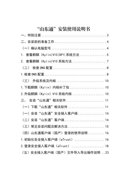
“山东通”安装使用说明书一、特别注意 (3)二、安装前的准备工作 (4)(一)确认电脑型号 (4)1.查看麒麟(Kylin)V10(SP1)系统方法 (5)2.查看麒麟(Kylin)V10系统方法 (7)(二)检查DNS配置 (8)1.检查DNS配置 (8)(三)升级系统及内核 (10)1.下载麒麟(Kylin)内核补丁包 (10)2.升级麒麟(Kylin)V10系统内核 (10)三、安装“山东通”相关软件 (11)(一)下载“山东通”相关软件 (11)(一)安装“山东通”安全接入客户端 (14)(二)安装“山东通”客户端 (14)(三)常见安装问题及解决方法 (15)(四)山东通客户端(国产)登录的使用说明 (16)1.初始化安全接入客户端(aTrust) (16)2.登录安全接入客户端(aTrust) (18)(五)安全接入客户端(国产)文件导入导出操作说明 ..23“山东通”安装使用说明书本安装说明书为各级部门技术人员提供参考,内容包含3款操作系统和3款CPU芯片型号的9种组合,从查看电脑参数型号、检查DNS配置、安装系统内核补丁包和“山东通”软件4个步骤详细介绍信创电脑安装“山东通”软件的流程,同时在“山东通”的下载中心提供各种组合的操作系统升级、内核补丁及山东通相关使用操作。
一、特别注意风险一:系统重新安装统信系统通过系统重装升级到1050属于全新系统升级,有以下风险:原系统存储的个人数据全部丢失,需要备份;导致省级、市级信创工作统一配发的wps、pdf、ofd、签章软件,以及杀毒软件商业授权失效,需要向省级、市级信创工作团队申请进行系统升级风险评估方可进行;可能导致部分办公或行业的应用软件及外设产品无法适配,需要向应用软件或外设产品牵头推广单位申请系统升级的风险评估后方可进行。
—3—“山东通”安装使用说明书—4—时代亿信终端安全登录万里红主机监控与审计奇安信终端安全管理中孚终端安全登录天融信主机监控与审计北信源终端安全登录风险三:内核补丁升级麒麟V10系统版本、统信(UOS)20系统的内核版本升级,属于内核补丁升级。
产品安装说明

产品安装说明为了确保顾客的使用体验,以下是本产品的安装说明。
请您按照以下步骤进行操作,以便正确和顺利地安装产品。
一、准备工作在安装产品之前,请确保您已经准备好以下物品:1.本产品的包装盒;2.产品说明书;3.安装所需的工具(根据产品的不同可能有所不同,一般包括螺丝刀、扳手等);4.电源线(如果需要连接电源的话)。
二、安装步骤1.打开包装盒,将产品取出。
请注意避免损坏产品或者其配件。
2.仔细阅读产品说明书,了解产品的使用方法、注意事项和安装步骤。
3.根据产品说明书的指引,选择一个合适的安装位置。
请确保该位置稳固且能够满足产品的安装要求。
4.如果产品需要固定在墙壁或其他表面上,请使用适当的工具进行固定。
在固定之前,请确认所选择的位置合适并没有其他障碍物。
5.根据产品说明书中的连接图示,将相关线缆连接到正确的接口上。
请确保连接稳固,没有松动。
6.如果需要连接电源,请将电源线连接到电源插座上。
在连接之前,请关闭电源开关以确保安全。
7.检查所有连接和固定点,确保产品安装牢固且位置正确。
8.根据产品说明书中的操作指引,打开产品的电源开关。
三、注意事项1.在安装产品之前,请仔细阅读产品说明书。
如果有任何疑问或者不明之处,请及时联系厂家或客服进行咨询。
2.请使用正确的工具进行安装,并根据说明书的指引操作。
不要随意更改或拆卸产品的部件。
3.在安装过程中,注意安全。
如果需要操作高处或者使用电源,请采取相应的安全措施。
4.安装完成后,请及时清理安装过程中产生的垃圾和杂物,保持安装环境的整洁。
5.如有其他特殊要求或者注意事项,请参考产品说明书中的相关内容。
四、售后服务如果在使用过程中遇到任何问题或者需要进一步的帮助,请及时联系我们的售后服务部门。
我们将竭诚为您提供最佳的解决方案和服务。
请您按照以上安装说明进行操作,祝您使用愉快!如有任何问题,请随时与我们联系。
感谢您对我们产品的支持!。
QSAN XCubeSAN快速安装手册说明书
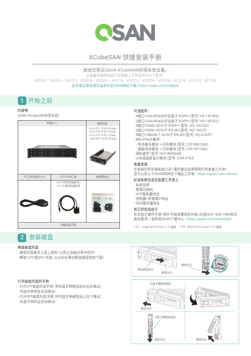
感谢您购买QSAN XCubeSAN 存储系统设备。
此安装手册将会指引您快速上手并适用于以下型号:XS5224 XS5216 XS5212 XS5226 XS3224 XS3216 XS3212 XS3226 XS1224 XS1216 XS1212 XS1226此手册之其他语言版本可至QSAN 网站下载:https:///m5jzpd打开磁盘托盘的手柄- 打开LFF 磁盘托盘手柄:将托盘手柄按钮由右向左移动; 托盘手柄将会自动弹出。
- 打开SFF 磁盘托盘手柄:将托盘手柄按钮由上往下移动; 托盘手柄将会自动弹出。
XCubeSAN 快速安装手册1 开始之前内容物QSAN XCubeSAN 机型包括:可选配件:- 4端口16Gb/8Gb 光纤信道子卡SFP+(型号:HQ-16F4S2)- 2端口16Gb/8Gb 光纤信道子卡SFP+(型号:HQ-16F2S2)- 4端口10GbE iSCSI 子卡SFP+(型号:HQ-10G4S2)- 2端口10GbE iSCSI 子卡RJ45(型号:HQ-10G2T )- 4端口1GBASE-T iSCSI 子卡RJ45(型号:HQ-01G4T )- BBU+Flash 模块: - 电池备份模块 + 闪存模块(型号:C2F-BM128G ) - 超级电容模块 + 闪存模块(型号:C2F-SP128G )- 滑轨套件(型号:SLR-RM3640)- USB 液晶屏显示模块(型号: LCM-U162)准备安装在安装您的存储系统之前,强烈建议您参照我们的准备工作表。
您可以在以下QSAN 的网页下载此工作表: https:///zk6ucs纪录系统信息在配置工作表上- 系统名称- 管理员密码- NTP 服务器地址- 控制器1的管理IP 地址- DNS 服务器地址其它的信息如下有关其它硬件手册、软件手册或兼容性列表(包括HDD 、SSD 、HBA 和交换机要求),请参阅QSAN 下载中心: https:///download1LFF : Large Form Factor / 3.5” 磁盘 2 SFF : Small Form Factor / 2.5” 磁盘2 安装磁盘解锁磁盘托盘- 磁盘托盘基本上是上锁的,以防止运输过程中损坏。
安装使用说明书
安装使用说明书(1)安装使用说明书是为本样本所有泵类产品而编辑的安装使用指南。
(2)设备应安装在平稳而固定的机架上或水泥地面上,底座的固定螺丝可用膨胀螺丝,大型设备可用底脚螺丝,本系列具有良好的动平衡和无噪音设计。
(3)安装完成后在接管线时建议在进出口安装一段金属波纹软管,以防机头负压变形不能正常工作。
(4)电机采用国内优质电机,电源380V,三相,50H z。
泵类系列设备进口在侧面,出口为上面,配对法兰标准为HG5010-58,PN=0.6Mpa。
(5)在接通电源后启动电机时,如果密封形式是单面密封,那首先先进物料后点动几下电机,在确认物料进入泵腔后,而且无异常响声时,可以正常启动电机;如果如果密封形式是双面密封,必须先通冷却水(油),冷却管在泵头与机座中间的2根细管,进出水方式:为下进上出,待冷却水(油)溢出后,点动几下电机,无异常响声时可以正常启动电机。
(6)在点动电机时一旦发现电流过大,跳闸,电机运转不正常时,首先检查泵头工作腔内是否有异物,或者用手盘动电机是否能转动,如果能转动,就要考虑电机及配电箱接线螺丝是否松动,电线是否符合规定等,以及是否关小闸门减少物料的流量。
(7)严禁石块,铁钉,木块等硬质物料进入泵体,必要时请在进出口处添加快开过滤器。
(8)在处理量大时或扬程高时,请在出口处增加一台相匹配泵作为输送,本系列设备进入口压力≤0.2 Mpa。
(9)较长时间不工作时,请将泵内物料排除干净,排污口在泵头的下面,检修安装时首先擦干净泵体内的每一个要件,然后逐件按顺序安装,完成后首先用手转一下电机,仔细听一下泵体内是否有异常摩擦声,如有请重装,直至无异常声响为止。
本说明书最终解释权属启东市东盛化工机械厂Installation Instruction(1) Installation Instruction is edited for all pump products on our catalogue.(2)Equipment should be installed in the stable and fixed rack or a concrete floor, the base of the fixed screw can be expansive screw. Large-scale equipment can use foot series have a good dynamic balance and noise-free design.(3)When take over the line after installation,we suggest that install a metal corrugated hose in the inlet and outlet, which prevents deformation of the nose suction from being not work..(4)Electric motor adopts superior quality,power supply 380V,three phase,50HZ. Pump series equipment imports in the side,exports above the matching flange 5010-58, PN = 0.6Mpa.(5)After connecting to the power the motor get started ,if the design of sealing is singel ,after putting into material and before starting the motor,It should make sure that the materials have been entered the pump chamber and no abnormal noise .If the design of sealing is double ,first passing cooling water (oil),cooling the two tubules between pump head and base .The way of inputing water and outputing water : inputing water from the bottom and outputing the water from the top ,after the overflowing of cooling water (oil),jop the motor seveal times ,if there is no abnormal noise ,the motor can be started normally !(6)While joping the motor ,if the current become big ,under voltage trip and the motor works unnormally ,firstly check whether there are some foreign body in the working chamber ,then check the motor and find whether it can move by hands ,if it can move ,then you need consider the motor ,the connecting screw of distribution box , and whether the wire is up to specification and try to close the gate little to reduce the flow of the materials .(7)Stones,nailes,wood such hard materials are prohibited into pump body,if necessary,please add up open filters at extrance and exit.(8)In large quantity or high lift, please add a match pump to transport at the exit; the inlet’s pressure of this series equipment ≤0.2 Mpa.(9)Longer period of time when not working,please rule out a clean pump materials,below the outfall in the pump head,repair the installation first wipe every element of the pump body, then piece by piece in order to install, after that turn the motor by hand, Listen carefully if it has unusual friction sound in the pump,if any, please reinstal until no abnormal sound up.Regarding the above instruction , Qidong dongsheng chemical machinery factory has the final y right to interpret.。
产品安装说明书

1.0 安装说明1.1 安装指南1.1.1 安装位置注意在安装配套设备时,请确保交流电源线、PLC、电磁阀、启动器、继电器或其它类型的电气接口设备与本产品保持适当距离,避免不同设备之间产生电磁干扰。
需特别注意安装变频器、伺服驱动器和开关电源等强干扰源设备时与本产品保持较远距离,此类设备的输入和输出线请务必采用屏蔽电缆线,并将屏蔽网接到系统的星形接地点。
1.1.2 环境注意事项1.2.1 电源要求1.1.3 应用环境本公司产品是依据工业应用环境而设计,设计的应用环境温度能够在-10℃~50℃的大多数工业环境中稳定工作,可能不适用于某些特别的室外环境,请使用者慎重选择!1.1.4 电气环境本公司产品已经通过测试符合欧盟CE电气认证的标准,即产品的电路设计可以抵抗电气噪声的干扰,但并不保证适应所有情况的电气噪声干扰,请使用者正确的布线和接地以确保正确使用。
1.2 电源连接在安装本产品前请确认符合所在区域或国家的电气标准,详情请向厂家咨询。
显示尺寸整机尺寸有效显示区尺寸3.5英寸102.5*60*17mm73.44*48.96mm液晶屏尺寸85.5*55*4mm螺丝孔间距96*40mm显示尺寸整机尺寸开孔尺寸3.5英寸115*71*25mm107*65mm有效显示区尺寸73.44*48.96mm建议开孔尺寸109*67mm系列 安装说明书AST 正面背面左侧面右侧面4.5 AST035串口屏通讯接口针脚定义(三选一):底面5.1 AST035触摸屏正面通讯接口针脚定义(三选一):5.0 触摸屏系列请前往本公司官网下载编程软件,注意匹配编辑软件版本:《HMILite_Setup_V2.1组态软件》。
2.0 编程软件显示尺寸整机尺寸有效显示区尺寸2.4英寸78.5*48.5*17mm48.96*36.72mm液晶屏尺寸60.5*42.5*4mm螺丝孔间距68.5*36.5mm显示尺寸整机尺寸有效显示区尺寸2.8英寸86.5*55.5*17mm57.6*43.2mm液晶屏尺寸69*50*4mm螺丝孔间距78*46.5mm显示尺寸整机尺寸有效显示区尺寸2.4英寸78.5*48.5*12mm48.96*36.72mm液晶屏尺寸60.5*42.5*4mm螺丝孔间距68.5*36.5mm显示尺寸整机尺寸有效显示区尺寸2.8英寸86.5*55.5*12mm57.6*43.2mm液晶屏尺寸69*50*4mm螺丝孔间距78*46.5mm4.1 AST024串口屏背面左侧面右侧面3.0 型号定义AST K 028NGD通信类型:D表示串口1为485通信,E表示串口1为232通信,T表示串口1为TTL通信外壳颜色: G表示外壳颜色为灰色触摸类型: N表示不带TP ,R表示带TP 屏尺寸: 表示产品型号尺寸 2.8寸K:表示带按键,E表示经济款屏系列:表示串口屏系列ASTE024/028 通讯接口针脚定义:4.4 ASTE028串口屏4.2 AST028串口屏AST024/028 通讯接口针脚定义(三选一):4.0 串口屏系列。
GW01 GW01-WIFI GW01-4G HMI 安装手册说明书

1.1环境要求工作环境温度:GW01/GW01-WIFI/GW01-4G 的设计规范可以保证它能够在32℉~122℉(0~50℃)的大多数工业环境中稳定工作。
1.2电源要求输入电压:DC12V-DC28V;特别需要注意与变频调速器和开关电源供应器保持较远的距离,这类设备的输入和输出电缆都必须采用屏蔽电缆,并将屏蔽网接到系统的星形接地点; 直流电源必须与交流主电源正确的隔离开;不要让GW01/GW01-WIFI/GW01-4G 设备和感性负载或控制器的输入电路共用电源。
注意:产品内部的快速熔丝在电源电压过高的时候可以起到保护作用,但并不能够确保内部电子元件不被损坏。
2.1尺寸图2.2安装说明GW01/GW01-WIFI/GW01-4G 的安装方式:轨道式安装和支架式安装。
2.3电源连接在连接电源前,请确认符合所有当地和国家的电气标准。
电源线缆请选择耐压值和电流值符合安全规定的线缆。
将产品背面接线端子的螺丝按逆时针方向旋松,插入电源电缆,然后顺时针拧紧接线端子的螺丝。
注意:将电源的正极接到标有‘DC24V’的端子上,直流的地接到标有‘GND’的端子上,地线接到标有‘FG’的端子上。
3.1电源端子3.2双以太网接口10M/100M 自适应以太网RJ45端口,接入云平台进行远程监控。
连接采用五类UTP 网线与带网口的设备连接端口作用用于HMI 组态的上/下载,系统参数的设置和在线模拟;构成多HMI 联机;与PLC 等通过以太网通讯;通过以太网口与PC 机通讯3.3WiFi 功能(仅GW01-WIFI 支持)功能:通过无线WiFi 连接,进行数据传输与下载3.44G 功能(仅GW01-4G 支持)功能:通过互联网4G 连接(默认外网路由优先级为4G)然后以太网;绑定了IP 的以太网PLC 通信,按选择的网口通信,来进行数据传输与下载。
3.5USB SLA VE 接口3.6COM0/COM2COM0/COM2通讯端口是9针D 型公座。
机械部件安装指南说明书
INSTALLATION:Check 1. mounting structure making sure it is rigid, level andwell supported. Inspect shaft to insure it is smooth (32 micro-inch finish or better), within commercial tolerances and free of burrs or rough spots.Disassemble and thoroughly clean all parts of the pillow2. block, Housing caps and liner caps are matched to their bases and should not be interchanged. Housing and liners should be interchanged as assemblies only.WARNING: Rust preventatives and solvents can be toxic and/or flammable. Follow directions and safety procedures recommended by their manufacturers.ATTENTION: Liner assembly has critical machines surfaces which are easily damaged. Use care in handling to protect these surfaces. Liner parts should be placed on a soft, CLEAN surface.Position 3. housing base on pedestal so that oil gauge is inthe position specified on the construction drawing. Do not tighten housing base to pedestal . Apply oil to the spherical seats in the housing base.Set liner base in housing base and apply oil to liner bearing4. surface.ATTENTION: Care should be taken when reinstalling coolant pipes. Use pipe sealant and tighten securely. Over tightening may result in liner damage.Apply oil to 5. shaft in the bearing area and set shaft in place.Check alignment 6. of pillow block by noting clearancebetween housing and shaft at each end of the housing—clearance should be uniform within 1/32”. Shim bearing pedestal where possible, otherwise use full length shims under base as required. Alignment of pillow block should be as accurate as possible. The self-alignment feature of the unit is to compensate for normal shaft deflection and possible setting of the supports.Place 7. oil rings around outside of lower liner and over shaft.Peen screws to insure that they are secure. Make sure rings rotate freely on shaft.Thrust Collars 8. , to be used in a fixed unit, should now beinstalled. Remove clamp screws from thrust collars and clean cracked joint with wire brush. Back off set screws to clear inside of collar. Place one collar half on shaft so shaft flinger groove is next to liner base in the non-expansion (fixed) bearing. Rotate collar half around shaft and place other half in position. Bring halves together at joint, making sure match at joint is perfect and insert clamp screws. There should be no offset at collar face. Tap halves together and tighten (Soc Hex) clamp screws alternately and evenly to torque specified in Table 2. Repeat above operation for opposite end of bearing. Assemble two collars on one bearing only . Tap collar up to WARNING: Because of the possible danger to persons(s) or property from accidents which may result from the improper use of products, it is important that correct procedures be followed. Products must be used in accordance with the engineering information specified in the catalog. Proper installation, maintenance and operation procedures must be observed. The instructions in the instruction manuals must be followed. Inspections should be made as necessary to assure safe operation under prevailing conditions. Proper guards and other suitable safety devices or procedures as may be desirable or as may be specified in safety codes should be provided, and are neither provided by Baldor Electric Company nor are the responsibility of Baldor Electric Company. This unit and its associated equipment must be installed, adjusted and maintained by qualified personnel who are familiar with the construction and operation of all equipment in the system and the potential hazards involved. When risk to persons or property may be involved, a holding device must be an integral part of the driven equipment beyond the speed reducer output shaft.INSTRUCTION MANUAL FOR 1-11/16” thru 3-7/16” SLEEVOIL®Plain-Water Cooled Pillow BlocksThese instructions must be read thoroughly before installation or operation.face of lower liner allowing a total clearance of .006”–.012” on sizes 1–11/16” and 1–15/16”, and .008”–.014” on sizes 2–3/16” through 3–7/16”, then tighten (Soc Hex) set screw to torque specified in Table 2. Collar should run parallel to end face of liner within .002”.Apply oil to bearing surface of 9.liner cap . Locate cap in place on lower liner making sure oil ring is free to rotate.The Sleevoil liners 1-11/16” thru 3-7/16” have upper halves that are normally reversible on the lower half. By design, they are not doweled together and therefore not match-marked. Two modifications which require match-marking of these ‘PL-WC’ liners, 1-11/16” thru 3-7/16” are:When using full (Type II) Bronze Thrust Plates • :Since liners are doweled together and machined as an assembly, care must be used to insure match marks are adjacent to each other and identical. The match marks will be on the Bronze Thrust Plate halves for b.t.p. face squareness after machining. Since the liner halves are doweled together, a liner with Type II Bronze Thrust Plates is rigid and does not allow the upper half to self-align to the plunger screw. To compensate for this loss of self-alignment, a special plunger screw washer is required. This special loose washer must be positioned on the upper liner spherical seat and under the plunger screw to insure alignment of liner bore to shaft in operation.When Liners Have a Cylindrical Bore • : Since the locationof the bore centerline to the liner dowels is then rigidly fixed, an upper liner reversed on a lower or interchanged halves from two different liners can severely change the clearances between shaft and liner bore.Tighten 10. housing base to pedestal. Torque bolts to value given in Table 3. Shaft should rotate freely.Thread 11.dust seal and seal spring into groove at end of housing base and around shaft. Hook ends of spring together; taking care not to overstress spring when stretching. Permanent set can cause loss of working load and looseness on shaft; resulting in oil leakage during operation. For size 3-7/16” thread dust seal and seal retainer into groove at end of housing base and around shaft. Slide free end of seal retainer thru clasp and pull tightly. Hold clasp with screwdriver and pull free end of retainer as tightly as possible with pliers. If tightened properly, it will be difficult to move seal sideways. Cut off excess material, and discard it so it won’t drop in housing bottom. If unit is furnished with auxiliary seals, install a second seal on each end.If using End Closure , neoprene discs should be installed at this time. Consult construction drawing for type of seal recommended .Apply Gasket Eliminator to Sleevoil housing base along outer 12.contour of joint. Loosen plunger screw and locate housing cap on base taking care not to damage dust seals or housing gasket. To reduce chances for leakage, a non-hardening sealant may be used under cap bolts. Torque housing bolts to value given in Table 4. The plunger screw must be loose until the housing bolts have been tightened .These Sleevoil ‘PL-WC’ housings have match marks permanently stamped on the water grommet pad starting in June 1988. These match marks permanently insure that parts stay paired and critical orientation of assemblies is maintained.Cap Loaded Bearings: Shaft must be held down to installcap, tighten plunger screw to recommended torque given in Table 4 with shaft held down. Mark position of plunger screw.Loosen plunger screw one complete turn and loosen shafthold down. Then tighten plunger screw while tightening shaft hold-down until plunger screw is tightened to the mark. Donot over-tighten shaft hold-down as this can misalign thebearing. Remove shaft hold-down and tighten plunger screw locknut.NOTE: Do not tighten plunger screw on accompanying base loaded bearing until cap loaded bearing has been installed and hold-down removed.Base Loaded Bearings: Tighten plunger screw to recommended torque given in Table 4 and tighten locknut.The13. oil level gauge may be located any distance from thepillow block by the use of a coupling and pipe of the desired length. The extended pipe must be supported so that itremains straight and perfectly level. Use a spirit level—do not guess. Use pipe sealer on all connections.IMPORTANT: Check and re-torque plunger screw to thespecified torque after 24 hours of initial start-up and then check and retorque periodically as required.Remove all pipe plugs and flush liner bore and housing14.thoroughly with solvent or cleaner. Reinstall pipe plugs using pipe sealer. Tighten securely.Each housing base has predrilled holes for doweling bearing 15.to base plate.LUBRICATION and OPERATIONSince the satisfactory operation of the pillow block depends almost entirely on the oil film being maintained between the shaft and liner bearing surface, it is recommended that a high grade straight mineral oil with rust and oxidation (R & O) inhibitors and anti-foam agents be used. Check equipment specifications for specific recommendations of oil viscosity by equipment manufacturer. Oil viscosity is determined by the equipment manufacturer and normally specified on the construction drawing or in the operating manual. Otherwise, see Table 1. Information regarding qualities and properties of specific oils should be referred to the lubricant manufacturer.TABLE 1—Recommended Oil ViscosityIf not specified by equipment manufacturer.Ambient Temp.Fahr. DuringStart UpSpeed SAE/ISO Oil RequiredBelow -10ºAll Consult Equipment Manufacturer-10º to 32ºAll SAE, 10/ISO3232º to 70ºLowHighLow SAE 20/ISO68 SAE 10/ISO32 SAE 30/ISO100Above 70ºHigh SAE 10/ISO32 for Light LoadsSAE 20/ISO68 for Heavy Loads Use high grade, high quality, well refined petroleum oils of the straight mineral type, with rust and oxidation inhibitor and anti-foam agent only.Table 2SLEEVOIL Size StandardOilCap.Fl.-Oz.COLLARCLAMP SCREW SET SCREWScrewSize(Soc Hex)WrenchTorque(In.-Lbs.)ScrewSize(Soc Hex)WrenchTorque(In.-Lbs.)1-11/1681/4–20NC1605/16–18NC140 1-15/1681/4–20NC1605/16–18NC140 2-3/16105/16–18NC3257/16–14NC350 2-7/16155/16–18NC3257/16–14NC350 2-11/16183/8–16NC5801/2–13NC600 2-15/16183/8–16NC5801/2–13NC600 3-7/16331/2–13NC14255/8–11NC1200Approximate viscosity:SAE 10–183 SUS at 100ºF; 46 SUS at 210ºFSAE 20–348 SUS at 100ºF; 57 SUS at 210ºFSAE 30–489 SUS at 100ºF; 65 SUS at 210ºFISO32 -158 SUS at 100ºF; 44 SUS at 210ºFISO68 -335 SUS at 100ºF; 55 SUS at 210ºFISO100–495 SUS at 100ºF; 66 SUS at 210ºFFill the pillow block with oil to the top of the center circle in the oil gauge. After placing into operation, remove inspection covers and check to make sure oil rings are bringing up oil. Operation should be checked frequently during the first few days. After some running of base loaded bearings only, loosen plunger screw 1/4 turn, then retighten as specified. This will allow the liner to align with the shaft. For cap loaded bearings, follow installation procedure. If noise develops, check alignment of housing, collar runout, plunger screw and all operating parts. Check all points and make sure all screws and nuts are tightened after several days operation. Maintain oil level above bottom of center circle at all times while unit is in operation.Oil Maintenance ScheduleDrain, flush, and refill with oil after 2 to 3 weeks of initial break-in operation. Since the satisfactory operation of the bearing depends entirely on an oil film being maintained between the shaft and the bearing liner surface, it is recommended that an oil analysis be performed at these regular intervals.Every 3 months for 24 hour/day service•Every 6 months for 8 hour/day service•Acceptability of oil should be referred to the lubricant manufacturer. If oil quality is acceptable then repeat this procedure in 3 month intervals. Visually check oil for contamination between oil analysis checks. Oil service life depends upon several factors such as ambient conditions, operating temperature and frequency of bearing starts and stops. It is recommended that the oil be changed at least once per year for unfiltered static applications. Removing contaminants through the use of either the OLF (Oil Level and Filtration) Unit or a circulating oil system can extend oil service life. Consult equipment manufacturer for more information.Oil film temperature in liner during operation should not exceed 180ºF. If in doubt, consult equipment manufacturer.Any question on installation, maintenance, or arrangement of coolant connection inlets and outlets should be referred to the original equipment manufacturer.Table 3SLEEVOILSizeStandardHOUSING/PEDESTAL BOLTSThreadSizeTorque(In-Lbs)1-11/161-15/165/85/8120012002-3/162-7/163/43/4210021002-11/162-15/167/87/8204020403-7/163/42100Table 4SLEEVOILSizeStandardPLUNGER SCREW HOUSING CAP BOLTSWrench Size(Soc Hex)Torque(In-Lb)ThreadSizeTorque(In-Lb)1-11/161-15/165/85/83003007/16–147/16–143603602-3/162-7/165/85/83504001/2–131/2–136006002-11/162-15/165/85/84504505/8–115/8–11108010803-7/165/85003/4–101920Reference Name of Part No. Reqd.Part Numbers1-11/161-15/162-3/162-7/162-11/162-15/163-7/16Non. Exp. Pillow Block1134215134216134217134218134219134220134221 Exp. Pillow Block1132984132985132986132987132988132989132990 Modular Housing1132941132942132943132944132993132994132996 Housing Machining 1133845133848133851133854133857133860133863 13● Housing Bolt4411439411439411112411113411117411147411186 14● Washer4419194––––––15Oil Level Plug2430012430012430012430012430012430012430012 16Drain Plug2430008430008430008430008430008430008430008 17Thermcouple Plug1––––43001243001243001218Thermcouple AdapterBush1––––430081430081430081 24● Gasket Eliminator1427359427359427359427359427359427359427359 26Inspection Cover ☐1405005405005405005405005405005405005405005 27Nameplate1133267133267133267133267133267133267133267 28Oil Gauge1430127430127430127430127430127430127430127 29Oil Gauge Gasket1418110418110418110418110418110418110418110 32Plunger Screw1422393422393422394422395422397422397422398 34Plunger Screw Nut1133368133368133368133368133368133368133368❍Seal Kit1389821389822389823389824389825389826389827 36● Dust Seal2133601133602133603133604133605133606132810 38● Seal Spring2133181133182133183133184133184133185133579 40Oil Ring1130044130045130047130049130050130051130054 43Circ Oil Drain Plug1––––––430016 44Liner Assembly 1133583133584133585133586132959132950132951❍● Brass Elbow2430068430068430068430068430068430068430068 46● Water Pipe2430158430158430162430162430162430162430162 49Grommet2133021133021133021133021133021133021133021 50Grommet Washer2133025133025133025133025133025133025133025 51Grommet Nut2407254407254407254407254407254407254407254❍Thermostat2––––––133116❍Heater2––––––132835❍Flex Water Hose Kit1133344133344133344133344133344133344133344❍End Cover❑❑133981133982133983133984133985133986133987❍Split End Plate ❒❒133124133125133126133125133128133129–❍End Plate Cap Screw ☐4417044417044417044417044417044417044–❍Aux Dust Seal Kit2––––––132811❍Housing End Cap Kit1––––––132542 52Split Thrust Collar ⏹2133250133255133260133260133270133275133280 54Thermostat Plug1––––––430012 56Heater Plug1––––––430012Includes housing cap and base, and parts listed immediately below Housing Machining.Liner assembly includes liner cap and base, and parts listed immediately below.● The parts marked are furnished with the assemblies under which they are listed.❍ Not shown on drawing.⏹ 2 required for non-expansion pillow blocks only☐ 4 required per end plate.☐ Nameplate must be ordered separately ❑ Neoprene disc for use when desired, or installations where shaft does not extend through housing. 1 required, for size 1 7/16” to 2 15/16”. 2 required for size3 7/16”.❒ Auxillary plate for bolting to one or both ends of housing where conditions are extremely dirty. Requires one additional dust seal and seal spring per end plate.Requires special matching on housing.World HeadquartersP .O. Box 2400, Fort Smith, AR 72902-2400 U.S.A., Ph: (1) 479.646.4711, Fax (1) 479.648.5792, International Fax (1) 479.648.5895Dodge Product Support6040 Ponders Court, Greenville, SC 29615-4617 U.S.A., Ph: (1) 864.297.4800, Fax: (1) 864.281.2433All Rights Reserved. Printed in USA.11/09 PRINTSHOP 100© Baldor Electric Company MN3055 (Replaces499959)。
安装说明书(仅供熟悉和学习用)
安装说明书(仅供熟悉和学习用)首先声明不适用苹果手机,只适合安卓系统手机,不要做侵犯他人隐私等违法用途监控范围:短信,通话记录,通话录音,手机QQ 微信聊天,GPS定位(需要拿到对方手机亲自安装)基本安装思路只有三步:1。
跟安装手机软件游戏一样,将下载的程序安装到手机2。
在手机里打开程序,设置好你的邮箱密码。
3。
测试邮箱,及监控是否正常。
完成后在程序里点隐藏图标(隐藏一定图标一定要在你确保一切正常以后)。
更具体安装说明:安装前准备一个邮箱帐号用来收发监控报告。
(如果是QQ邮箱,需要到邮箱后台设置-帐户最下面打勾POP3/SMTP选项)如果手机有装360卫士需要先到360杀毒-设置-自动联网查杀关了提示:安装后程序有图标,安装测试完后在程序里点隐藏,但不要提前点隐藏。
1。
用91手机助手安装程序到手机或者在手机里直接下载安装到手机。
电脑安装前请选择安装路径到手机内存。
(如果手机安装没有选择,请安装后在设置-应用-所有里找到“系统” 查看是否安装到了内存,如果不是进行移动。
一定要选择安装到内存,否则无法开机自动运行)2。
安装完,桌面里多了个“系统”,直接打开。
设置好邮箱,邮箱密码,点击发送测试邮件看是否成功,是否能收到邮件。
点开启监控,再返回退出。
3。
打电话发短信,每个功能测试一次看能不能收到邮件报告,如果手机有弹出授权之类的都点允许-记住。
4。
重起手机然后进程序看下监控是否打勾,如果打勾说明程序可以正常自动启动,点隐藏图标。
如需重新设置,拨打77886挂断显示图标。
(如果没有自动启动,请查找手机上安全工具的自启管理进行设置)(如果提前隐藏后打77886挂断无法显示图标的话,设置-应用-所有程序里找到系统清除数据卸载重装)(如果打开了防卸载后,要卸载请先到系统设置-安全-设备管理器取消一下系统的打勾)小M手机/Miui系统安装后请在手机进行以下2步:1。
到设置-应用-全部找到“系统”-点权限管理- 点“我信任该程序”跟“自动启动” (或者在安全工具或其它安装的安全软件里)2。
安装流程说明书
安装流程说明书【安装流程说明书】一、前言感谢您选择我们的产品,本安装流程说明书旨在详细介绍产品的安装步骤,以帮助您顺利进行安装并使用。
请您仔细阅读并按照本手册的步骤进行操作,保证安装过程顺利进行。
二、准备工作1.确认产品配送是否完整:请仔细核对产品包装箱内的物品清单,确保配送的产品齐全,并未损坏;2.准备所需工具:根据产品安装所需工具清单,确认是否准备齐全,并确保工具的可用性;3.选择安装位置:根据产品使用要求,选择合适的位置进行安装,并确保该位置符合产品的使用环境要求。
三、安装步骤1.拆箱检查与准备(1) 将产品的包装箱放置在一个平整、宽敞的空间上,并小心地打开包装箱;(2) 将产品及附件取出,并仔细检查产品是否有损坏,同时核对配送清单上的物品是否完整;(3) 为了保证安装的顺利进行,清理安装场地,确保场地干净整洁,为后续的工作做好准备。
2.组装产品(1) 参照附带的安装图纸或说明书,依据所提供的图示步骤,按照顺序进行产品的组装;(2) 使用正确的工具和配件,确保组装过程中的每一个连接点都可靠牢固,以确保产品稳定性和安全性。
3.连接电源和调试(1) 根据产品的电源要求,正确连接产品电源;(2) 按照产品说明书中的相关步骤,进行产品的调试,确保产品的正常运行;(3) 如遇到调试问题,请及时参考产品说明书中的故障排除方案,或联系客户服务中心进行咨询。
4.安装辅助设备(如有)(1) 根据产品配套设备的说明,依据提供的图示或文字步骤,安装和连接辅助设备;(2) 确保辅助设备与产品的连接牢固可靠,并进行相关设置和调试。
5.安装完成与验收(1) 安装完毕后,仔细检查产品的每一个连接点,确认产品已经安装到位,并确保没有松动或未连接好的部分;(2) 做好安装记录,记录产品的型号、序列号以及安装日期等信息;(3) 如已安装辅助设备,进行相关功能测试,确保设备的正常工作;(4) 完成验收后,将安装场地恢复原状,清理残留物并妥善处理废弃物。
通用安装使用说明书范文

通用安装使用说明书范文◇1概述1.1概述本安装使用说明书包括深蓝泵业有限公司EAP、EAPG、ANS、某L、Z 某、ESH、ESHK、EHG、SCS、DCS、EDS、HDD、LYA、LG、LC、LDB、HZW、PP系列产品的所有安装、试车、使用和维修的基本知识,具体各个规格产品的结构特点、使用参数、拆卸、安装见其专用安装使用说明书。
所有维修工程师和现场服务的全体专职人员在安装和试车前必须阅读本手册并且经常使用它。
1.2质量保证产品质量保证依据定货合同执行。
1.3安全规则1.3.1使用手册的指示标志-不注意安全规则会导致人员危险而表示的危险符号:-电压警惕符号:-需要注意而没注意从而导致的机械故障或运行故障的安全规则符号:注意-直接在装置上的指示符号,如:旋转方向箭头、泵名牌、接口说明符号等,为了使用方便,要保持这些标志的完整、清晰。
1.3.2人员的资格和培训服务、维修、检查和安装的全体人员必须具有从事这种工作的资格。
每个人的责任、权限和检测范围必须固定和清楚。
如果没有一定的相关知识,可经过厂家进行必要的培训和教导。
对于使用者,还需要完全理解生产商提供的操作手册。
1.3.3安全操作说明-泵只有在数据单中所规定的范围内运行,才能保证其正常工作。
在任何情况下,都不要超过数据单中提供的数据极限值。
-如果辅助装置(如冷却装置、最小流量装置、润滑装置、密封冲洗装置)发生故障,会导致泵电压增高、密封失效,轴承温升增加等现象发生。
因而确保泵的辅助装置运转正常。
-若泵零件温度很高或很低以至于会对人员造成伤害时,应采取防护措施,避免接触。
-为防止停车时回流现象出现,必须安装止回流装置。
-运行前必须检查安全防护装置是否可靠(如联轴器护罩)。
-输送危险污染环境的液体要符合环境保护法。
-应经常检查易损件,并保证适时更换已磨损的零件,如:叶轮、口环等。
-装配和拆卸过程中,要有稳定的紧固装置,且要防止零部件掉下引起意外情况发生。
Allura Flex安装指南说明书

Installation Guidance Note:Allura FlexGeneral AdviceThe appearance, performance and durability of the installed floorcovering will be determined to a large extent by the quality of the prepared subfloor and the conditions in which they are laid. As with any resilient floor covering irregularities in the subfloor will be apparent in the finished flooring.The installation of Allura Flex should be carried out in accordance with BS8203:2017 installation of resilient floor coverings - Code of practice. Areas to receive flooring should be free from other trades, fully enclosed and weather tight.Subfloors should be clean and free of all contaminants, smooth, sound, even and permanently dry.Note: contaminants can affect the adhesion of the new floor covering and/or cause migrating stains. It is therefore important that contaminants such as cleaning chemical residues, old adhesive residues and remains of old floor coverings such as residues of carpet tile backings are removed or, where permissible, isolated with an appropriate subfloor treatment.Areas to receive flooring shall be adequately lit to allow for proper inspection of the substrate, installation and for final inspection.Always conduct moisture tests on all substrates. All ground-based level floors should have an effective moisture barrier.It is essential that the laying area is at a steady temperature of 18 to 27o C for 48 hours prior to, during, and for 24 hours after installation. The material and adhesive should be conditioned in the same environment for at least 24 hours prior to the installation. Where the floorcoverings have been stored or transported immediately prior to delivery in temperatures below 10o C the acclimatisation period should be extended to 48 hours.Prior to installation tiles should be checked to ensure that the correct colour, batch number and quantity have been received and that the material is in good condition. No claim will be accepted for incorrect colour, pattern or obvious damage if the material has been fitted.Use material from the same batch/dye lot. The use of different production batches will always result in visible shade differences. The batch number is clearly marked on the material packaging and must be checked before commencement of installation.Store Allura Flex tiles and planks in cartons stacked, maximum 5 cartons, ensuring that they fully supported and are laying flat.Do not remove more tiles from the box than can be installed within 1 hour.Allura Flex is occupier ready on completion of the installation. However, if the newly installed floor is going to be subjected to site traffic, particularly heavy, high point load wheeled traffic, the floor should be protected during this phase (see “on completion” at the end of this guide).Note: Installation over the following substrates falls outside the scope of BS8203:2017 and the recommendations below should be followed:Raised Access FloorsThese should be smooth, level and clean of all contaminants. Degreasing may be necessary on steel faced panels (chemical cleaning agents should be thoroughly rinsed/neutralized after cleaning). All old adhesive/floor covering residues must be removed.Raised access flooring panels have a tendency to settle shortly after installation and this should be taken into account when assessing the appearance of the Allura Flex tiles or planks fitted onto raised access flooring systems. Ridges between uneven raised access floor panels and/or gaps between adjacent panels will telegraph through to the finished tile installation.Panels should be checked before commencing installation to ensure that they are close fitting and level. Uneven or loose floor panels should be levelled or re-fixed before installing Allura Flex tiles or planks.Notes:•Incidental low-level light will exaggerate any unevenness in the subfloor.•If a suitably flat and level raised access panel substrate cannot be achieved, the raised access floor should be overlaid with plywood or levelled using a suitable self-levelling smoothing underlaymentcompound.•See additional advice below for the installation of Hungarian point planksOld resilient flooringIt is recommended that existing floor coverings are removed, and that the subfloor is prepared in accordance with BS8203:2017.If existing floor coverings cannot be removed contact Forbo Technical Services for further advice.Underfloor heatingAs with all Forbo floor coverings, Allura Flex can be used in conjunction with under-floor heating systems.It is imperative that the underfloor heating systems have been previously commissioned and found to be functioning correctly prior to the floor finish being installed. Ensure that the underfloor heating system is switched off 48 hours prior to the floor covering installation commencing and remains off for at least 48 hours after the installation is complete.During the period of decommissioning of the underfloor heating system, an alternative heating source should be provided, if required, to ensure that the area of installation is kept at a constant temperature of 18o C – 27o C. Gradually increase the temperature over a number of days by only a few degrees per day until the desired room temperature is reached.The temperature should never exceed the industry agreed maximum of 27o C at the underside of the floor covering (the adhesive line). Failure to follow these guidelines can result in the floor covering de-bonding, joints opening, and on some occasions discolouring, all of which can occur within a long or short period of time. Further information on the requirements for underfloor heated subfloors can be found in BS8203:2017.Adhesive Recommendations and applicationThe following information is provided for general guidance. In all cases the adhesive manufacturers’ full usage and application instructions should be consulted and followed before commencing the installation.Allura Flex tiles should be installed using a high grab, plasticizer migration resistant tackifier adhesive. Forbo recommends Forbo Eurocol 542 Eurofix Tack Plus. If alternative products are to be used consult with the supplier for more information, guidance and warranty.Use a short pile roller to apply the tackifier. It is essential that tackifiers are allowed to dry to a tacky finish before laying the floor covering. Failure to do so could result in a permanent non-release bond.Note:1.The adhesive must be spread evenly over the entire floor area including up to perimeter edges2.Porous substrates may require priming with a diluted application of the adhesive.3.Always clean away excess adhesive with a damp cloth before it is allowed to dry.In most applications Forbo Eurocol 542 tackifier adhesive will be sufficient in heavy commercial usage areas, however, where tiles or planks are liable to be subject to heavy static or dynamic loads, they should be fully adhered using Forbo Eurocol 640 Eurostar special (EC1 Low emission adhesive).Note: Forbo Flooring recommends to fully adhere Allura Flex in areas liable to be subjected to abnormal temperature variation in use, for example, retail premises with glazed window fronts, open spaces in offices with large glazed areas, conservatories etc. The use of a high temperature adhesive that is compatible with the floor covering and the subfloor is recommended.The installation, on completion, should be rolled with an appropriate weighted roller (recommended 68kg) to ensure good contact with the adhesive. Areas that cannot be rolled with the large roller e.g. abutments such as architraves or skirting boards should be rolled with a hand roller or pressed into the adhesive with a rubbing hammer.InstallationFor the installation direction of Allura Flex tile please note the following:•Stone, concrete and sand tiles may be laid either in bond (monolithic) or brick pattern•Textile designs should be installed tessellated.Tessellated Monolithic BrickTraditional wood designs do not require shuffling prior to installation, but dry laying will identify best use of design.Like the natural material, some designs will vary in tone and colour. This is intentional and gives the floor a more authentic appearance.Note:see additional installation advice below for Hungarian point” planksSetting outForbo tile products are installed using conventional tile installationtechniques.The correct starting point for setting out a tiled floor is traditionally thecentre of the area - although this may not be the final starting point whentile laying begins. Some adjustment of the starting point may be required,for example, to avoid small perimeter cuts, where the tiles are to be laidwith a border, or with designs such as Hungarian Point.Figure AIn corridors and small spaces, it may be simpler to work lengthwise fromone end, using the centre line as a guide.The centre line is drawn as follows: a chalk line is snapped from centre of wall A-B (=E) to the centre of wall C-D (=F). The centre of line E-F is found (M). Draw a perpendicular line through M using the 3:4:5 method to establish G-H (Figure A).Starting at centre point M, measure out lengthwise and width wise to the walls. Wherever possible, cuts of less than 60mm or so should be avoided as these are more likely to come loose at some stage in the life of the installation. Adjust the position of lines E-F and G-H if necessary.Laying tiles or planksBegin laying tiles at the starting point, ensuring that the tile is laid exactly along the layout lines. If the first few tiles are not installed accurately, the entire installation will be affected. Lightly roll each row of planks with a hand roller to ensure an initial firm adhesive bond.Note: In a large area, two or more fitters may be placing tiles at the same time. As finger pressure in butting the tiles or planks together may be slightly different, we suggest starting from a common point and work away from it to avoid tiles or planks going out of bond.Remove fresh adhesive residue immediately with a clean white damp cloth. Dried adhesive residue can be removed with a clean white cloth and soapy water.Fully adhered installationIn situations where the tiles or planks are being fully adhered the time it takes to mark and cut the border tiles must be taken into consideration when planning the installation. Without adequate planning, it is likely that the working time of the adhesive in the area of the border tiles will be exceeded before the tiles are installed, which will result in an inadequate bond of the border tiles. The successful installation of border tiles is best accomplished by following one of two strategies:a.When laying out tiles, determine the edge of a field tile a comfortable distance from each wall and thensnap chalk lines around the perimeter of the room. When spreading adhesive, use these lines as a guide to stop spreading adhesive and install the field tiles up to the adhesive spread lines. Once the field tiles have been installed, the border tiles can be “dry” fitted (before spreading the adhesive). After theborder tiles have been cut, adhesive can be applied in the area of the border tiles and the tiles can be placed into the adhesive.b.Plan the sequence of spreading adhesive so that the border tiles can be cut and placed into the adhesivebefore the adhesive working time has been exceeded.Hungarian PointThis design is made up of left and right planks which are installed together in rows (option 1) or either side of a standard plank (option 2). Each box has an equal number of A and B planks packed face-to-face and back-to-back in the box.Hungarian Point Laying Option 1 Hungarian Point Laying Option 2Note: As with any geometric design, irregularities or undulations in the subfloor can result in the bond of tiles or planks drifting during installation. This is particularly important with the installation of Hungarian point planks if the points of the planks are to meet consistently and particular attention should be given to the preparation of the subfloor to ensure that the highest standard of subfloor regularity/level is achieved i.e. within SR1 surface regularity standard (no greater than 3mm variance within 2 metres).On completion of the installationFirst impressions may have more impact on the client than hours of skilled fitting.The completed installation should be cleared of scrap material and debris, the floor swept or vacuumed, and any traces of adhesive residues removed from the floor and skirtings.If the floor covering is to be protected from other trades or site traffic prior to project completion, a protection product should be chosen that is appropriate for the type and level of traffic likely to be experienced and the potential for impact, scratching or indentation damage.In many cases it is customary for the initial floor preparation to be left, or subcontracted, to a professional cleaning and maintenance contractor who will have the staff and equipment to do the job thoroughly.If the optimum performance of any new floor covering is to be achieved, it is important that the correct cleaning and maintenance procedures are used from day one. Cleaning and maintenance guides for all Forbo Flooring products are available for download at: /alluraflexCleaning and maintenance guides should be passed onto the main contractor, client or end user as appropriate on completion of the installation, and before any hand over clean is started.If in any doubt contact us:Forbo Flooring UK LtdTel: 0800 0282 162Fax: 01772 646912Samples**************************************Additional Reference documents and information:Forbo Floor Coverings Installation Guide: BS8203:2017 installation of resilient floor coverings - Code of practiceThe CFA Guide to Contract Flooring: https:/// (Tel: 01159 411126)。
安装步骤说明书
安装步骤说明书尊敬的用户,欢迎您购买我们公司的产品。
为了确保您能正确、快速地安装和使用该产品,特别为您准备了详细的安装步骤说明书。
请您仔细阅读以下内容,按照步骤一步一步地操作。
1. 物料准备在开始安装之前,请确保您已经准备齐全所需的物料。
以下是安装所需的物料清单:- 主机设备- 配套配件和固定螺丝- 电源线- 数据线- 安装工具(如螺丝刀、扳手等)2. 安装位置选择选择一个合适的位置安装主机设备,确保其稳固并且便于接入电源和数据线。
请考虑以下几点:- 离电源插座近,方便供电- 通风良好的场所,避免过热- 干燥且避免进水的环境- 尽量避免与其他电子设备过于靠近,以免干扰3. 设备安装使用合适的工具,按照以下步骤将主机设备安装到确定的位置上:- 打开设备包装,取出主机设备和配套配件- 使用固定螺丝将主机设备固定在选择的位置上,确保稳固可靠- 连接电源线和数据线,确保连接牢固且接口无松动4. 电源连接请按照以下步骤正确连接电源线:- 确认电源线的接口与主机设备的电源接口相匹配- 将电源线插头插入主机设备的电源接口- 将电源线的另一端插入电源插座5. 数据线连接请按照以下步骤正确连接数据线:- 确认数据线的接口与主机设备的数据接口相匹配- 将数据线插头插入主机设备的数据接口- 将数据线的另一端插入外部设备的数据接口(如果需要)6. 通电测试完成上述步骤后,您可以执行以下操作进行通电测试:- 确保主机设备的电源开关处于关闭状态- 插入电源线的插头到电源插座中- 打开主机设备的电源开关- 观察设备是否能顺利启动,是否有任何异常声音或指示灯闪烁请注意:如果在通电测试过程中发现任何异常情况,请立即关闭设备电源,并联系我们的客服人员进行咨询和解决。
7. 附加功能设置按照您的需求和产品说明书中的指引,进行附加功能的设置和调整。
根据不同产品的要求,可能会需要进行一些额外的步骤和配置。
至此,您已经完成了产品的安装步骤。
安装使用说明书

LSS1.0-1.0-Y(Q)型蒸汽锅炉安装使用说明书编制:审核:批准:有限公司目录安装说明一、安装前的准备工作二、锅炉大件的安装三、燃烧器的安装四、省煤器及烟囱的安装五、管道、阀门及仪表附件的安装六、水压试验七、烘炉和煮炉八、严密性试验及安全阀的调整九、试运行十、分段验收和整体验收使用说明一、使用前的规定二、对使用单位的要求三、对操作人员的要求四、锅炉使用前的准备工作五、点火六、正常运行七、排污八、停炉九、维护保养和检验十、停炉保养十一、说明安装说明一、安装前的准备工作锅炉运到现场后,为了迅速投入运行,安装前必须做好下列工作:1、本锅炉安装依据《蒸规》和GB50273《工业锅炉安装工程施工及验收规范》与本说明的要求进行。
2、锅炉安装单位,必须持有省质量技术监督部门发给的与锅炉等级安装类型相符合的锅炉安装许可证。
锅炉安装前必须将锅炉的平面布置及有关建筑距离的图纸送交当地锅炉压力容器安全监察机构审查同意,否则不能施工。
3、在锅炉安装前和安装过程中,当发现受压部件存在影响安全使用的质量问题时,必须立即停止安装。
4、锅炉安装前,安装单位必须组织有关人员,遵照国家有关法规熟悉锅炉图纸,按装说明书等技术文件,编好安装顺序后,方可进行安装。
5、基础准备确定锅炉大件安装基准线。
a:纵向基础中心线----由炉前至炉后沿底座中心线。
b:横向基础中心线-----锅炉底座前沿。
基础深度由土建设计院根据基础载荷和当地的土质情况而定,待基础凝固后,方可安装锅炉就位。
二、锅炉大件的安装锅炉大件安装在基础上时应保持水平。
锅炉就位后,锅炉的支座应保持水平,允许倾斜不大于5mm。
否则应将低的一面用垫铁垫高。
三、燃烧器的安装燃烧器的固定:将燃烧器的烧嘴和燃烧器面板对准在同一轴线上。
中心线偏差夹角不大于2°,然后将燃烧器上的固定板紧贴在燃烧器接口上,用螺栓固定,燃烧器的油路以及电路安装详见燃烧器安装说明书。
四、省煤器及烟囱的安装省煤器整件出厂,安装前应做好支架,将省煤器吊装至安装位置。
无线路由器安装指南说明书

Before proceeding with the wireless router installation, familiarize yourself with the contents of the product package, especially the Setup Manual on the CD and the animated tutorials on configuring PCs for networking.Follow these instructions to set up your router.Prepare to Install Your Wireless Router•For Cable Modem Service: When you perform the wireless router setup steps be sure to use the computer you used when you first set up your cable Internetconnection.•For DSL Service: You may need information such as the DSL login name/e-mail address and password in order to complete the wireless router setup.•Observe the wireless placement and range guidelines in the Setup Manual. First, Connect the Wireless Router to the Internet1.C ONNECT THE WIRELESS ROUTER TO THE COMPUTER AND THE MODEMa.Turn off your computer.b.Turn off and unplug thecable or DSL broadbandmodem.c.Locate the Ethernetcable (cable 1 in thediagram) that connectsyour modem and PC.d.Disconnect the cable at the computer end only, point A in the diagram.e.Securely insert the Ethernet cable from your modem into the Internet port ofthe wireless router.f.Securely insert the blue cable that came with your wireless router into aLAN port on the router, and the other end into the Ethernet port of yourcomputer.Your network cables are connected and you are ready to restart your network.2.R ESTART YOUR NETWORK IN THE CORRECT SEQUENCEWarning: Failure to restart your network in the correct sequence could preventyou from connecting to the Internet.a.First, plug in and turn on the broadband modem. Wait about 2 minutes.b.Now, plug in the power cord to your wireless router and wait 1 minute.st, turn on your computer.Note: For DSL customers, if ISP provided software logs you in to the Internet,do not run that software. Y ou may need to go to the Internet Explorer Toolsmenu, Internet Options, Connections tab page where you can select “Never diala connection.”d.Check the wireless router status lights to verify the following:•Power:The power light should turn solid green. If it does not turn solidgreen, see the Troubleshooting Tips in this guide.•Link/ACT: The Link/ACT light should be lit. If not, make sure theEthernet cable is securely attached to the wireless router Internet portand the modem, and the modem is powered on.•Wireless: The Wireless light should be lit. If the Wireless light is not lit,see the Troubleshooting Tips in this guide.•LAN: A LAN light should be lit. If a LAN light is not lit, check that theEthernet cable from the computer to the router is securely attached atboth ends, and that the computer is turned on.3.U SE THE S MART W IZARD TO CONFIGURE THE WIRELESS ROUTERa.Connect to the router by typing http://192.168.1.1 in the address filed ofInternet Explorer or Netscape® Navigator.b.For security reasons, the router has its own user name and password. Whenprompted, enter admin for the router user name and password for the routerpassword, both in lower case letters.Note: The user name and password are not the same as any user name orpassword you may use to log in to the Internet.The wireless router will display the NETGEAR Smart Wizard page.ClickOK to proceed.Note: If you cannot connect to the wireless router, verify your computernetworking setup. It should be set to obtain both IP and DNS serveraddresses automatically, which is usually so. For help with this, please seethe Setup Manual or animated tutorials on the CD.c.Follow the Smart Wizard prompts to connect to the Internet.You are now connected to the Internet and the wireless feature of the wirelessrouter is enabled! Next, configure your wireless computer.Now, Set Up a Computer for Wireless Connectivity1.C ONFIGURE THE COMPUTER’S W IRELESS S ETTINGSa.If you are not already logged in the WGM124 configuration utility, typehttp://192.168.1.1in your Internet browser and click Enter.b.When prompted, type in admin for the router user name and password forthe router password.c.Click Wireless Settings in the WGM124 main configuration menu. Select aRegion. Do not change the other settings.d.Click Apply to save your changes.2.C ONFIGURE THE COMPUTER ’S W IRELESS A DAPTER S ETTINGSConfigure the wireless adapter of your computer to match these settings GEAR, Inc. wireless adapters display a list of available wireless networks, and, when wireless security is disabled, you simply choose yours from the list and connect.For a non-NETGEAR wireless adapter, configure it to match your settings exactly. If you changed the default Network Name (SSID), be sure to use what you set in the wireless router.Warning:The Network Name is case sensitive. Entering nETgear will not work.December 20043.V ERIFY W IRELESS C ONNECTIVITYConnect to the Internet from a computer with a wireless adapter. You are now wirelessly connected to the Internet!Important : Implement wireless security options appropriate to your needs. These settings enable basic wireless connectivity that let you set up your wireless computers and test wireless Internet access through the router.The NETGEAR wireless router provides many wireless security options. Your wireless computer may not support all of these options. Please read theNETGEAR manual to identify the wireless security features of your router that satisfy your requirements and work with your wireless computer. Troubleshooting TipsHere are some tips for correcting simple problems you may have.Be sure to restart your network in this sequence:1) Turn off the modem, wireless router, and computer; 2) Turn on the modem, wait two minutes; 3) Turn on the wireless router and wait 1 minute; 4) Turn on the computer.Make sure the Ethernet cables are securely plugged in.•The Internet status light on the wireless router will be lit if the Ethernet cable to the wireless router from the modem is plugged in securely and the modem and wireless router are turned on.•For each powered on computer connected to the wireless router with a securelyplugged in Ethernet cable, the corresponding wireless router LAN port status light will be lit. The label on the bottom of the wireless router identifies the number of each LAN port.Make sure the wireless settings in the computer and router match exactly.The Wireless Network Name (SSID) and security settings of the router and wireless computer must match exactly.Make sure the network settings of the computer are correct.•Ethernet cable and wirelessly connected computers must be configured to obtainIP and DNS addresses automatically via DHCP. For help with this, please see the animated tutorials on the CD or the Setup Manual Appendix C on the CD.•Some cable modem ISPs require you to use the MAC address of the computerregistered on the account. If so, in the Router MAC Address section of the Basic Settings menu, select, “Use this Computer’s MAC Address.” The router will then capture and use the MAC address of the computer that you are now using. You must be using the computer that is registered with the ISP. Click Apply to save your settings. Restart the network in the correct sequence.Check the router status lights to verify correct router operation.•If the Power light does not turn solid green within 2 minutes of turning the routeron, reset the router as described in the Setup Manual on the CD.•If the Wireless light does not come on, verify that the wireless feature is turnedon according to the instructions in the Setup Manual on the CD.Advanced user access.Technically advanced users who want to bypass the configuration assistant can do so by logging in to the router at /basicsetting.htm with the user name of admin and the password of password in lower case letters.Technical SupportThank you for selecting NETGEAR products.After completing the Smart Wizard configuration assistant, register your product at /register . Registration is required before you can use our telephone support service.Go to wireless router for product updates and web support.©2004 by NETGEAR, Inc. All rights reserved.NETGEAR is a registered trademark of NETGEAR, Inc. in the United States and/or other countries.Other brand and product names are trademarks or registered trademarks of their respective holders. Information is subject to change without notice.WIRELESS FEATURE DEFAULT SETTING Network Name (SSID)NETGEAR SecurityDisabled。
安装说明书模板
安装说明书模板
一、安装概述
1.1 说明安装的目的和重要性
1.2 列出所需的材料和工具清单
1.3 安装的预期结果和效果
二、准备工作
2.1 确保安装环境适合
2.2 安装前的检查和测试
2.3 要求安装人员的资质和技能
三、安装步骤
3.1 步骤一:拆包和查看零件清单
3.2 步骤二:安装基础设施
3.3 步骤三:组装零部件
3.4 步骤四:连接电源和电缆
3.5 步骤五:调整和校准
3.6 步骤六:测试和验收
四、注意事项
4.1 安全注意事项
4.2 可能遇到的常见问题及解决方法
4.3 维护和保养建议
4.4 使用说明和注意事项
五、附录
5.1 安装过程中的图片和图表
5.2 安装的技术参数和规格
5.3 保修和售后服务信息
六、常见问题解答
注意:以上为安装说明书的模板概要,根据具体情况进行调整和完善。
请在编写正式的安装说明书时,按照上述大纲逐步展开详细说明,确保内容的准确性、完整性和易读性。
在每个章节中,可以适当增加
文字或细化步骤,以满足实际需求。
同时,根据目标受众的特点,选
择合适的表格、图表和插图来辅助说明。
安装说明书是非常重要的,它提供了安装过程的详细指导,确保用
户能正确、顺利地安装和操作目标产品。
因此,在编写安装说明书时,一定要严格按照实际情况来进行,确保内容的准确性和可读性,避免
出现任何影响阅读体验的问题。
最后,通过合理的排版和精练的表达,能够使整份安装说明书显得整洁美观,语句通顺,全文表达流畅。
希望以上提供的安装说明书模板能对您有所帮助,谢谢!。
Growatt ShineWiFi-X 快速安装指导说明书
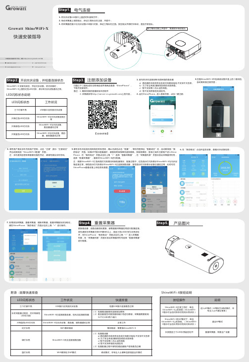
Growatt ShineWiFi-X快速安装指导扫描以下二维码,或在谷歌商店或苹果商店搜索“ShinePhone”,下并安装软件。
载注册添加设备详细信息及最新用户手册,请到 下载备注:1. 确保安装的是最新版本的软件2. 详情请参考上的内容 。
【安卓&苹果】400-931-3122 F +86 755 2747 2131Step1.转动采集器上端的锁头,保证三角标志在正面,并居中;将采集器的接口与光伏设备USB接口对接,保证三角标在正面。
按压锁头并顺时针转动,直至拧紧锁头。
2.3.电气连接Step3. 1. 首先将手机连接到有无线网络的路由器5.填写手机所连接无线网络名称及密码,确认无误后点击“配置”,等待页面弹出“配置成功”后,自动跳转到“我的电站”页面。
如果APP提示配置超时,请查询附录故障快速排查表。
排除故障后,登录之前所注册账户进入ShinePhone电站”页面点击右上角“+”选择“查看采集器” ,在“采集器列表”页面长按此采集器序列号,选择“配置采集器”,重新对ShineWiFi-X进行配置。
注:观察ShineWiFi-X三色网络灯闪烁情况判断配置情况,配置过程中,红色指示灯闪烁表示ShineWiFi-X与连接正常,绿色指示灯闪烁表示ShineWiFi-X已连接到路由器,蓝色指示灯闪烁表示设备已通信正常,此时可在Phone查看设备上传信息及数据。
,在“我的光伏设备Shine2. 运行ShinePhone , 进入登录页面,点击一键注册;1. 将光伏设备USB接口上盖逆时针旋转拧开;6. 在“我的电站”点击所监控设备,查看光伏设备信息;E service@W 开启光伏设备,并检查连接状态Step2.ShineWiFi-X 安装完成后,开启光伏设备。
初次安装时,ShineWiFi-X上面的红色LED闪烁,表示和光伏设备通讯正常。
LED闪烁状态说明LED闪烁状态工作状况三个灯都不亮USB接口没找到光伏设备只有红色LED灯闪烁ShineWiFi-X与连接正常光伏设备只有绿色LED灯闪烁ShineWiFi-X与、路由器通讯正常光伏设备只有蓝色LED灯闪烁ShineWiFi-X与、路由器、服务器通讯正常光伏设备a路由器的无线名称应由英文和数组组成,不支持中文名称。
- 1、下载文档前请自行甄别文档内容的完整性,平台不提供额外的编辑、内容补充、找答案等附加服务。
- 2、"仅部分预览"的文档,不可在线预览部分如存在完整性等问题,可反馈申请退款(可完整预览的文档不适用该条件!)。
- 3、如文档侵犯您的权益,请联系客服反馈,我们会尽快为您处理(人工客服工作时间:9:00-18:30)。
好莱坞及卡通转场的安装
这个好莱坞安装包安装路径为直接解压到d盘。
(一)安装好莱坞视频特效插件:
解压缩:这个压缩包内有三个文件:
1.HFX.exercise InstallKit
2.5c 是好莱坞FX5.1和4.58 GOLD安装主程序;
2.Hfx4GLD.vfx 是《会声会影》调用4.58 GOLD的链接文件;
3.KEYGEN.exe 是注册算号机;
安装步骤:
1、点击HFX.exercise InstallKit 2.5c,安装过程是全自动的,它会自动选择安装目录:D:\Program Files\Pinnacle\Hollywood FX GOLD;
Hollywood FX 5.1也安装在D:\Program Files\Pinnacle文件夹下。
2、FX5.1转场文件的转移(本盘会自动进行转移)
会声会影只能调用Hollywood FX 4.58 GOLD 的转场,虽然安装了FX 5.1,但需要把Hollywood FX 5.1中的转场放入4.58 才能使用,
具体做法:
(1)打开Hollywood FX 5 文件夹(在D 盘的Program Files\Pinnacle文件夹下里);
(2)把该目录下Effects、Objects、Images三个目录下的所有文件复制到:Hollywood FX GOLD 安装目录相应的文件夹下。
(3)删除4.58 的Orgs目录下的 和 两个文件。
(在安装卡通转场特技时,它会自动删除)
3、与会X3进行链接(本盘将自动进行)
将链接文件Hfx4GLD.vfx复制好,打开《会声会影X3》安装目录的vfx_plug 文件夹,即打开C:\Program Files\Corel\Corel VideoStudio 13\vfx_plug文件夹,把复制的Hfx4GLD.vfx文件黏贴进去;
4、打开《会影X3》主程序,再点击会声会影《全功能编辑器》,在“转场”里(打开“全部”如果有“Hollywood FX”这一项,说明《会声会影X3》可以调用Hollywood FX GOLD了,由于Hollywood FX 5。
1的转场文件已经转移到Hollywood FX v4.58 GOLD,所以《会声会影X2》已经可以调用包含FX5。
1转场文件的FX_v4.58 GOLD了。
5、注册:
这个安装包(Hollywood FX Gold v4.58 GOLD )安装开始直到结束,并不
显示提示注册的信息,但一定要先注册,否则不能进行去水印。
方法:在《会声会影编辑器》随意输入两个视频片段,插入Hollywood FX 转场,点“选项”,“自定义”,调出Hollywood FX 操作界面,就可以看到Hollywood FX 操作界面下面有“现在注册”的提示。
点“现在注册”,出现对话框,其中可以找到
SN:HFX45-GLD-535744-85S
及ID:
打开《Hollywood文件夹》内的注册算号机机,
复制输入SN 和ID ,点击"Generate",即可得到激活号,输入后就注册了。
(二)安装卡通转场特技,运行安装文件即可。
卡通转场密码:45850
要注意的是选择安装路径,是Hollywood FX GOLD 所在位置,
即D:\Program Files\Pinnacle\Hollywood FX GOLD
Hollywood FX的卡通转场特技按装包包含下面自动功能:
对Hollywood FX 4.58 部分来说
1、无论原来 4.58 是否已经汉化。
都要对其进行汉化更新,
2、对系统文件覆盖前,都自动进行了只读取消处理;
3、自动删除了\Orgs 下全部文件;
万一打开好莱坞,在转场菜单内没有增加卡通和婚庆转场列表,可以手工进行删除。
删除4.58 的Orgs目录下的 和 两个文件以后卡通和婚庆转场列表赫然在目了,这个情况有可能发生但也极少发生,遇到这种情况问题一定在这里。
对Hollywood FX 5.1 部分
1、自动增加和覆盖了必要的系统文件;
2、自动删除了\Album 文件夹中的文件
本盘将FX 5.1 的转场文件转移到FX 4.58以后,可以将Hollywood FX 5.1文件夹删除。
卡通转场特技安装完毕之后,自动弹出去水印工具的界面,点击《自动移除序列号和修复转场》就可以去掉水印了。
卡通转场特技包的安装,进行了汉化、多余文件的删除和水印的清除。
至此好莱坞安装完毕。
