东联智通WAT89-EC6酒检仪参数信息
FSL100系列耐烟探测器文档说明书

Detectores de llamaserie FSL100 UV, UVIR, IR3Flame DetectionLa gama está compuesta por detectores de llama UV, UVIR e IR3 Todos disponen de un sofisticada tecnología de detección y deanálisis de señal para detectar fuegosrápidamente y rechazar las falsas alarmas.El FSL100 puede ser pequeño y ligero para facilitar su instalación, pero está diseñadopara trabajar en entornos exigentes, tanto en interiores como en exteriores, así como enatmósferas potencialmente explosivas.Con un gran campo de visión, puede detectar una amplia gama de tipos de fuegos distintos, incluyendo los causados por hidrocarburos y por otros elementos. Disponible en UV, UVIR y 3IR,apto para cualquier aplicación.Aptos para multitud de aplicaciones• Disponibles UV, UVIR e IR3• Detecta fuegos causados por hidrocarburos y otras sustancias• Puede usarse en atmósferaspotencialmente explosivas• Funcionamiento en interiores y exteriores • Modelos disponibles en color rojo de alta visibilidad o blanco discretoAlto rendimiento• Homologados según las normas EN54-10 y FM3260 estándares para detectores dellama• Autocomprobación completa automática • Autocomprobación manual remota opcional Rápido y Fiable• Sensores y microprocesador de alta velocidad• Sofisticados algoritmos de análisis• Supervisión continua del estado del sistema • Rechazo de falsas alarmasCostes reducidos en su ciclo de vida• Elementos duraderos• Compensación de presión para evitar la contaminación• 2 años de garantía• Compre con confianzaInstalación y uso sencillos• Salidas de relé y mA de serie• Carcasa ligera de GRP• Entradas pretroqueladas• Soporte giratorio de montaje opcional• Disponible lámpara de comprobación de largo alcanceDetectores de Llama UV, UVIR, IR3Los detectores de llama de la serie FSL100 de Honeywell ofrecen una detección robusta, rápida y fiable de fuegos con llama en una amplia gama de aplicaciones.• Adecuado para aplicaciones eninteriores, por ejemplo, campanas de extracciónde humos y áreas de almacenamientode hidrógeno• Solución eficaz para materialesque arden con bajas temperaturas,p. ej., azufre• Detecta fuegos provocados porhidrocarburos (madera, papel,gasolina) así como por hidrógenoe hidrocarburos ligeros, como elmetanol y metano• Buena resistencia a las interferencias derivadas de:- Luz directa y reflejada del sol- Luz artificial, p. ej., tubosfluorescentes y lámparashalógenas cubiertas de vidrioFSL100-UVFSL100-UV/IR• Análisis de la frecuencia deparpadeo de la llama para mejorarel rechazo de falsas alarmas• La metodología de detección dual permitedetectar eficazmente una amplia gama defuegos de hidrocarburo y no hidrocarburos• Monitoriza las llamas de hidrocarburospesados (madera, papel, gasolina) perotambién de hidrógeno e hidrocarburosligeros como metanol y metano• Buena resistencia contra las influencias de:- Luz directa y reflejada del sol- Luz artificial, como tubos fluorescentesy lámparas halógenas con recubrimientode vidrio- Arcos y descargas eléctricas (estáticao p. ej., de motores eléctricos)- La radiación procedente de la soldaduraeléctrica siempre ésta se realicea una distancia superior a 3 metrosdel detector (una varilla de soldaduracontiene compuestos orgánicosque presentan fenómenos de llama)• Análisis de la frecuencia de parpadeode la llama para mejorar el rechazo de falsas alarmas • Especialmente adecuado parahidrocarburos líquidos y fuegos sucios • Menos afectado por contaminación de las ventanas o por fuegos con humo• Detecta llamas de hidrocarburos pesados (madera,papel, gasolina) e hidrocarburos ligeros, como el metanol y metano• Buena resistencia contra las influencias derivadas de:- Luz directa y reflejada del sol - Luz artificial, p.ej., tubosfluorescentes y lámparas halógenas cubiertas de vidrio- Arcos y descargas eléctricas (estática o p. ej., de motores eléctricos)- La radiación procedente de la soldadura eléctrica siempre que ésta se realice a una distancia superior a 3 metros del detector(una varilla de soldadura contiene compuestos orgánicos que presentan fenómenos de llama)• Especialmente apto para fuegos con humo.Análisis de la frecuencia de parpadeode la llama para mejorar el rechazo de falsas alarmasFSL100-IR3APLICACIONESApto ✓ Recomendado ✓✓*Póngase en contacto con su representante de HoneywellESPECIFICACIONES GENERALESDetección de gas de Honeywell AnalyticsSEDE CENTRALCENTROS DE ASISTENCIA TÉCNICAHoneywell Analytics puede ofrecer soluciones de detección de gas que cumplan los requisitos de todas las aplicaciones y todos los sectores. Póngase en contacto con nosotros de las siguientes formas:Europa, Oriente Próximo y África Life Safety Distribution AG Javastrasse 28604 Hegnau SuizaTel: +41 (0)44 943 4300Fax: +41 (0)44 943 4398**************************Departamento de Servicio de atención al cliente:Tel: 00800 333 222 44 (número gratuito)Tel: +41 44 943 4380 (número alternativo)Fax: 00800 333 222 55Tel. de Oriente Próximo: +971 4 450 5800 (detección fija de gas)Tel. de Oriente Próximo: +971 4 450 5852 (detección portátil de gas) Tenga en cuenta:Se ha puesto el máximo empeño en garantizar la exactitud de esta publicación; no obstante, declinamos toda responsabilidad por los posibles erroresu omisiones. Se pueden producir cambios tanto en los datos como en la legislación, por lo que se recomienda encarecidamente obtener copiasactualizadas de la legislación, las normas y las directrices. Esta publicación no constituye la base de un contrato.13475_H_FSL100_DS01155_V2_ES 11/16© 2016 Honeywell AnalyticsEMEA:**********************US:***************************AP:***************************AméricaHoneywell Analytics Distribution Inc.405 Barclay Blvd.Lincolnshire, IL 60069EE. UU.Tel: +1 847 955 8200Tel. gratuito: +1 800 538 0363Fax: +1 847 955 8210***********************Asia PacíficoHoneywell Analytics Asia Pacífico#701 Kolon Science Valley (1)43 Digital-Ro 34-Gil, Guro-Gu Seúl 152-729CoreaTel: +82 (0) 2 6909 0300Fax: +82 (0) 2 2025 0328Tel. de la India: +91 124 4752700**************************。
酒精测定仪的计量标准
酒精测定仪计量标准一、量程范围酒精测定仪的量程范围是指其可以测量的酒精浓度的范围。
一般来说,根据不同的应用场景和检测要求,仪器的量程范围也会有所不同。
通常情况下,酒精测定仪的量程范围在0%-100%酒精度之间,很少有超过这个范围的。
二、精度等级精度等级是衡量酒精测定仪性能优劣的一个重要指标。
它表示的是仪器测量结果的准确程度。
一般来说,一个高精度的酒精测定仪测量的精度等级应在3%以下,更高精度的则要求在1%以下。
需要注意的是,精度等级是在一定测量条件下得出的,不同条件下可能会有所不同。
三、响应时间响应时间是酒精测定仪在检测酒精浓度时需要的时间。
它与仪器内部的设计和工艺有关。
一个好的酒精测定仪应该具有较快的响应速度,以便能够快速地给出测量结果。
一般来说,响应时间在几秒钟到几十秒之间不等,具体取决于仪器型号和应用场景。
四、测量重复性测量重复性是指酒精测定仪在多次测量同一酒精浓度时的测量结果的一致程度。
一个好的酒精测定仪应该具有较好的重复性,以保证多次测量的结果具有较好的一致性。
一般情况下,重复性误差应在±1%以内。
五、温度影响酒精测定仪的测量结果会受到温度的影响。
这是因为温度的变化会导致酒精的挥发和扩散,从而影响仪器的测量结果。
因此,一个好的酒精测定仪应该具有较小的温度影响,以保证在不同温度下测量的结果具有较好的一致性。
六、线性度线性度是指酒精测定仪的输出信号与酒精浓度之间的比例关系是否为线性关系。
如果输出信号与酒精浓度之间存在非线性关系,则需要进行线性校正。
一般来说,一个好的酒精测定仪应该具有较好的线性度,以保证测量的准确性。
七、零点漂移零点漂移是指酒精测定仪在使用一段时间后,其输出信号与零点之间的偏差。
这种偏差会影响测量的准确性。
因此,一个好的酒精测定仪应该具有较小的零点漂移,以保证测量的准确性。
八、量程漂移量程漂移是指酒精测定仪在使用一段时间后,其输出信号与满量程之间的偏差。
这种偏差会影响测量的范围和精度。
UT890C+ D真实RMS数字多功能手动测量器操作手册说明书

Range 600mV 0.1mV 0.001V 0.01V 0.1V 1V6V 60V 600V 1000VResolution Accuracy ±(0.5%+4)±(0.5%+2)±(0.7%+10)Range 600Ω0.1Ω0.001kΩ0.01k Ω0.1k Ω0.001MΩ0.01M Ω6k Ω60k Ω600k Ω6M Ω60M ΩResolution Accuracy ±(0.8%+5)±(0.8%+3)±(1.0%+25)Operating ManualI. General IntroductionThis brand new UT890C+/D Operating Manual is a handheld 3-5/6 digit True RMS Digital Multi-meter featuring stable performance and high reliability. Its whole circuit design utilizes a large scale integrated circuit that uses ∑△ADC converter as its core and is further equipped with full function overload protection, making it an ideal tool for users to measure the followings: DC and AC voltage, electric current, resistance, capacitance, frequency, temperature (UT890D/C+), diode, triode and continuity test.Safety Rules and Instructions● This unit is designed and produced in strict accordance with GB4793, Safety Requirements for Electronic Measuring Instrument and Safety Standards coded as IEC61010-1 and IEC1010-2-032. It complies with safe standards, such as double insulation, over voltage (CAT II 1000V, CAT III 600V) and class of pollution II. Please follow the instructions contained in this manual, otherwise the protection provided by this unit may be impaired.● You should not use this unit unless its back cover is properly secured in place, otherwise you are exposed to shock hazard. ● The range switch should be switched to a correct range.● Check the insulation layer of the test leads to ensure no damaged or broken cable.● The red and black test leads should be well inserted into the jacks that are in compliance with the measurement requirements to ensure good contact.● The input signal should not exceed the specified limit value to avoid shock or unit damage.● It is prohibited to change range when measuring voltage or electric current so as to avoid unit damage.● Damaged fuse must only be replaced with fuse with identical specification.● To avoid electric shock, the potential difference measured between “COM” and earth “ ” should be no more than 1000V. ● To avoid electric shock, test with great caution in case the voltage to be measured maybe higher than DV 60V or AC 30Vrms. ● Battery should be replaced in time so as to ensure measurement accuracy when the LCD displays “ ”.● Power should be turned off immediately upon the test is completed and battery should be taken out if it may not be used for a long period of time.● Do not use the unit under an environment with high temperature and high humidity, especially not store it in a wet place as the dampened unit may perform badly.● Please do not change the circuit of the unit arbitrarily so as to avoid unit damage or safety hazard.● Maintenance: Please use wet cloth and mild detergent rather than abrasive material or solvent for the cleaning of its exterior housing.III. Characteristics● More than 30 functional ranges are available.● LCD display, visible area 63×29mm.● Over range display “OL”.● Maximum displayed value 5999.● Overload protection for all ranges.● Auto power off.● Temperature scope:Working temperature: 0℃~40℃(32℉~104℉) Storage temperature: -10℃~50℃(14℉~122℉)● Low battery indicator: The symbol “ ” will be displayed at top left of the LCD.● It has functions, including data hold, measurement of maximum/ minimum value, relative measurement, backlight, etc.II. Symbol DescriptionIV. Technical IndexesAccuracy: ±(α% reading plus figure), 1 year warranty period Environment Temperature: 23℃±5℃ Relative humidity:<75%1. DC VoltageInput impedance: 1GΩfor the range of 600mV while 10MΩ for all2. AC VoltageRange 6V 0.001V 0.01V 0.1V 1V60V 600V 750VResolution Accuracy ±(0.8%+3)±(1.0%+10)Input impedance: 10MΩfor all the ranges.Frequency scope: 40Hz – 1KHz (Only applicable to sine wave and triangular wave, but only being referable for other waves whose frequencies are equal or higher than 200Hz.)Guaranteed Accuracy: within 5~100% of its range and allow less t han 5 figures of remaining reading in case of short circuit.Overload Protection: 750Vrms or at a peak value of 1000Vp-p.Display: True RMS 3. DC CurrentRange 60μA 0.01μA 0.001m A 0.01mA 0.1m A 0.01A6mA 60mA 600mA 20AResolution Accuracy ±(0.8%+8)±(1.2%+5)±(2.0%+5)Maximum input current: 20A (measuring electric current between 5A and 20A, testing time ≤10 seconds, Interval≥15 mins). Measuring voltage drop: 600mV when at its full range.4. AC CurrentRange 6mA 0.001m A 0.01m A 0.1mA 0.01A60mA 600mA 20AResolution Accuracy ±(1.0%+12)±(2.0%+3)±(3.0%+5)Frequency scope: 40Hz – 1KHz (Only applicable to sine wave and triangular wave, but only being referable for other waves whose frequencies are equal or higher than 200Hz.)Guaranteed Accuracy: within 5~100% of its range and allow less Maximum input current: 20A (measuring electric current between 5A and 20A, testing time ≤10 seconds, Interval≥15 mins) Measuring voltage drop: 600mV when at its full range Display: True RMS 5. ResistanceRange of 600Ω: measured value=displayed value - value shown when Overload protection: 600Vrms. 6. CapacitanceRange 9.999n F 0.001nF0.01nF~ 0.1μF 1μF 10μF99.99nF~ 999.9μF 9.999mF 99.99mFResolution Accuracy±(5.0%+35)±(2.5%+20)±(5.0%+10)10mF≤C≤20mF:±(10.0%+5)>20mF:reading is for reference onlyRange: Auto (Reading for distributed capacitance of test leads may be shown when the unit is in open circuit. It is recommended to use7. FrequencyRange9.999Hz ~10.00MHz0.001Hz ~0.01MHzResolutionAccuracy ±(0.1%+5)Range: Auto Input frequency:≤100KHz: 100mVrms≤Input frequency≤30Vrms ;>100kHz~1MHz: 200mVrms≤Input frequency≤30Vrms; >1MHz: 600mVrms≤Input frequency≤30Vrms; Overload protection: 600Vrms .8.Diode & Buzzer Continuity TestRange DescriptionDisplay forward voltage of the diode under test (approximate value) and the range scope is 0~3V.If it is equal or less than 10Ω, the buzzer beeps, indicating circuit is closed; if it is equal or more than 100Ω,the buzzer remain silence, indicating open circuit with a voltage of approximately 1V. Overload protection: 600Vrms .9. hFE Test for Transistors Range DescriptionhFETest ConditionIt can be used to test hFE specificiations for Transistors of NPN or PNP type. Display range: 0-1000βBase current is about 10μA, Vce is about1.2V 10. Temperature Test (Only for UT890C+)Accuracy ±3±5±(1.0%+3)±(1.5%+5)±(2.5%+5)±(2.0%+3)Function RangeResolution Temperature ℃Temperature ℃-40~0℃1℃>0~100℃>100~1000℃-40~32F 1F>32~212F >212~1832FV. How to Use it:Instructions before operating(1). Once the unit is powered up, please check the 9V batterycontained in this unit, and if the battery voltage is insufficient, there will be asymbol “ ” being displayed on the screen, then the battery should bereplaced to ensure measurement accuracy.the jacks for test leads warns that for the prevention of internal circuit from being damaged, the input voltage or current should not exceed the rated value.(3). Before measuring, the range switch should be switched into the range needed.123456 (see Fig. 1)①② LCD③ Combination keys: MAX MIN/④ Range switch⑤ Jack for transistor testing ⑥ Input Jack1. DC Voltage Measurement(1). Insert the black test lead into “COM”, while insert the red test lead into “V”.the test leads in parallel with the power or load under test, the polarity shown by the unit is the polarity of the terminal connected by the red test lead.1) If the voltage being measured remains unknown, turn the range switch into the maximum range first and then gradually adjusting it downward.2) If “OL” is shown on the LCD, it indicates that it has exceeded the range, so the range should be switched into a higher one.higher than 1000V should be input into the unit, as though it is possible to display a higher voltage, but this may incur a risk of damaging internal wiring!4) In case the input impedance is around 10MΩ, it may result in measurement error if such load is connected into a circuit with high impedance. Under most circumstances, if the circuit impedance is less than 10kΩ, then the error is ignored (0.1% or even lower).5) Especially be cautious to avoid shock when measuring high voltage. 2. AC Voltage Measurement(1) Insert the black test lead into “COM”, while insert the red test lead into “V”.REV.1DATE:2015/07/07 (2) Switch the range switch into the range “ ”. Then connect thetest leads in parallel with the power or load under test.higher than 750V should be input into the unit, as though it is possibleto display a higher voltage, but this may incur a risk of damaginginternal wiring!1) If the current being measured remains unknown, turn the rangeswitch into the maximum range first and then gradually adjusting itdownward.2) If “OL” is shown on the LCD, it indicates that it has exceeded therange, so the range should be switched into a higher one.voltage higher than 600mA should be input into the unit, otherwiseindicates that no voltage higher than 20A should be input into theunit, otherwise F2 fuse may be blown.3. DC Current Measurement(1) Insert the black test lead into “COM” first, then when measuringcurrent equal or less than 600mA, insert the red test lead into “mAμA”,otherwise, insert the red test lead into the jack for 20A.test leads in series with the load under test, the polarity shown bythe unit is the polarity of the terminal connected by the red test lead.4. AC Current Measurement1) Insert the black test lead into “COM” first, then when measuringcurrent equal or less than 600mA, insert the red test lead into “mAμA”,otherwise, insert the red test lead into the jack for 20A.2) Switch the range switch into the range “ ”. Then connect thetest leads in series with the load under test.Refer to No. 1), 2) and 3) of the Notes for DC current measurement.5. Resistance(1) Input the black test lead into “COM”, while insert the red testlead into “Ω”.(2) Switch the range to range “Ω” and connect the test leads inparallel with the resistance under test.NotesNotesNotesNotesNotesNotes1) To ensure measurement accuracy, for the range of 600Ω:measured value=displayed value - value shown when test leads areshort connected.2) If the resistance under test is higher than the range selected, theunit will display “OL”. Then a higher range should be selected. Forany resistance higher than 1MΩ or even higher, it may take a fewseconds for the reading to become stable, which is normal whenmeasuring high resistance.3) The red test lead can also be used to check whether or not F1or F2 has been blown. If the “mAμA” jack is tested to be 1MΩ and“A” jack is tested to be 0Ω, then the fuse acts good. If the unit displays“OL”, then the fuse has been blown.4) In case of no input, i.e. the case of open-circuit, the unit displays“OL”.5) When checking the impedance of an internal circuit, the circuitunder test must be cut off from all power sources and all capacitivecharge must be discharged.6. Capacitance MeasurementThe unit may display a reading even if there is no input at all, whichis the distributed capacitance of the test leads. For the measurementof a resistance less than 1μF, this value has to be deducted from thefinal measured value to ensure measurement accuracy. Therefore,the relative measurement function of this unit can be used to haveit automatically deducted for the convenience of checking reading.1) The unit will display “OL” in case the capacitance to be measuredhas been short connected or exceeds the maximum range of theunit, the displayer will show “OL”.2) For the measurement of large capacitance, it is normal for theunit to take several seconds to stabilize its reading.3) To avoid unit damage or harm to the personal safety, the capacitorto be tested must have all its residual charge discharged before thetest, which is especially the case for capacitor with high voltage.7. Frequency Test1. Insert the red test lead into “Hz” jack, while insert the black testlead into “COM” jack.2. Switch the range switch into the range “Hz”. Then connect thetest leads in parallel with the frequency source, frequency valueThe input frequency must comply with the requirements stipulatedby the Technical Indexes.8. Test of DiodeInsert the black test lead into “COM” jack, while insert the red testlead into “V” jack (the polarity of red test lead is “+”). Switch the rangeswitch into the range “ ”. Then connect the test lead with thediode under test, the reading is the forward voltage drop of thediode. If the diode under test is in open circuit or its polarity is reverseconnected, the unit will display “OL”. For silicon p–n junction,approximately 500~800mV is generally considered normal.1) When measuring a connected diode, the circuit under test mustbe first cut off from all power sources and all capacitors must haveall their residual charge discharged.2) Only a diode with approximately 0~3V voltage can be measured.9. Buzzer Continuity TestInsert the black test lead into “COM”, while insert the red test leadinto “V”. Switch the range switch into the range “ ” and then connectthe test leads into the circuit under test. If both ends of the circuit hasa resistance higher than 100Ω,it is considered that the electric circuitis disconnected and the buzzer remains silence. If the resistancebetween both ends is found to be equal or less than 10Ω, it is thenconsidered that the electric circuit is well connected and the buzzerWhen measuring an energized circuit, the circuit under test mustfirst be cut off from all power sources and all capacitors must haveall their residual charge discharged.10. hFE Test for Transistors(1) Switch the range switch to the range “hFE”.(2) Once the transistor has been confirmed whether to be a NPNor PNP type, insert its base, emitter and collector separately intocorresponding jacks on the panel.(3) Approximate hFE value will be displayed on the displayer. Testcondition: 1b≈10μA, Vce≈1.2V。
酒精检测仪标准参数
酒精检测仪标准参数酒精检测仪是一种用于检测人体呼出气体中酒精浓度的设备,广泛应用于交通管理、公共安全和工作场所等领域。
在购买和使用酒精检测仪时,了解其标准参数是非常重要的。
本文将详细介绍酒精检测仪的标准参数,帮助用户更好地了解和选择合适的设备。
1. 检测原理。
酒精检测仪主要通过检测被测试者呼出气体中的乙醇浓度来判断其酒精含量。
常见的检测原理包括半导体传感器、红外吸收和燃料电池等。
不同的原理会影响到检测仪的精度、响应时间和使用寿命,用户在选择时需要根据实际需求进行考量。
2. 检测范围。
酒精检测仪的检测范围是指其能够准确检测的酒精浓度范围。
一般来说,常见的检测范围为0.00-0.40mg/L。
在选择酒精检测仪时,需要根据实际使用场景来确定所需的检测范围,以确保检测结果的准确性。
3. 精度和误差。
酒精检测仪的精度是指其检测结果与实际值之间的偏差程度。
通常用百分比或固定数值来表示,如误差范围为正负5%或正负0.01mg/L。
精度是衡量酒精检测仪性能的重要指标,用户在购买时应选择精度高的产品,以确保检测结果的准确性。
4. 响应时间。
酒精检测仪的响应时间是指从开始检测到得出检测结果所需的时间。
响应时间的长短直接影响到检测仪在实际使用中的效率和便利性。
一般来说,响应时间在几秒到几十秒之间,用户可以根据具体需求选择合适的响应时间。
5. 工作温度和湿度。
酒精检测仪的工作温度和湿度范围是指其能够正常工作的环境条件。
一般来说,工作温度范围为-10℃至50℃,工作湿度范围为20%-90%RH。
用户在使用酒精检测仪时需要注意避免超出其工作条件范围,以免影响检测结果和设备寿命。
6. 电池寿命。
酒精检测仪通常采用电池供电,因此电池寿命是一个重要的参数。
一般来说,电池寿命在几百次到几千次检测之间,用户在购买时需要关注电池寿命,并注意及时更换电池以确保设备正常使用。
总结。
酒精检测仪的标准参数包括检测原理、检测范围、精度和误差、响应时间、工作温度和湿度、电池寿命等。
8910C 电能质量分析仪
发货清单
分析仪套件中包括下列物品,请仔细核对,如有不同,请及时联系本公司。
表 1-1 发货清单
序号
名称
数量பைடு நூலகம்
单位
备注
1
电能质量分析仪
1
台
2
电压测试线
5
条
5 色测试线
3
电流钳
把
用户确认量程和数量
4
仪表用电源线
1
根
5
仪表用 0.5A 保险丝
2
只
6
仪表使用说明书
1
份
7
合格证
1
张
8
仪表检测报告
1
份
9
保修单
1
份
第 1 页 共 39 页
电能质量分析仪
第一章 常 规
简 介:
本章主要介绍与8910C电能质量分析仪(以下简称为“分析仪”)有关的许多常规方面的重要内容。 包括: • 注意事项。 • 保证及责任条件。 • 产品合格声明。 • 发货清单: 分析仪套件中应包含的物品清单。 • 联系信息。 • 安全须知: 请先阅读!
测量模式
1. 常态: 当前基本测试数据总览。适用于对电力系统的基本数据的实时监测。 显示趋势----显示连续监测数据的变化情况。 显示记录----显示已经发生并被记录在分析仪内存中的常态数据的相关信息 显示事件----显示已经发生并被记录在分析仪内存中的极值事件的相关信息。 记录开始/记录终止----控制常态记录的开始/结束。 参数设置----与常态数据有关的参数设置。
3. 相量图: 当前测试信号的相量图。适用于对电力系统的基本数据的实时监测。 显示数据----显示当前测试信号的相量数据。
4. 不平衡度: 当前各分相测试数据。适用于对电力系统的不平衡度的实时监测。 显示趋势----显示连续监测数据的变化情况。 显示记录----显示已经发生并被记录在分析仪内存中的不平衡度数据的相关信息。 参数设置----与不平衡度有关的参数设置。 记录开始/记录终止----控制不平衡度记录的开始/结束。
九球高分辨角度指示器(API)Model 8810A 双同型旋转 解析度测量以及可选的参考供应说明书

One optional Reference supply •Direct replacement for all 8810’s•High resolution touch-screen•Two isolated Input Channels•0.0001° Resolution•±0.004°Accuracy (Optional ±0.0015°)•LXI compatible•Programmable display options•Auto-ranging Signal and Reference•47 Hz to 20 KHZ Frequency Range•DC rate or angle output•Auto Phase Correction•Optional 2.2 VA internal Reference•Measures and displays ReferenceVoltage, frequency, and VL-L•Ethernet, USB, IEEE-488 andparallel ports•| compliantGENERALThis second generation API, Model 8810A, truly represents a major step forward in synchro to digital conversion technology. The use of an intelligent DSP design eliminates push buttons and allows all programming to be done either via an integrated touch-screen or a mouse interface. In addition, IEEE-488, Ethernet, and USB interfaces have been added to extend remote operation capabilities. The display can be set for one of three display modes; 0-360º, ±180°, or Degrees, Minutes, Seconds. A wide (47 Hz to 20 KHz) frequency range is standard. As an option, a programmable 2.2 VA internal reference supply can be specified.Improved flexibility is provided by two fully independent inputs that can be used to simultaneously read two separate input signals or can be combined to measure multi-speed Synchros or Resolvers. The gear ratio, for the two-speed mode, is programmable from 2:1 to 255:1Built-in phase correction eliminates errors caused by quadrature and harmonics when reference and signal are out of phase by as much as 60°.The 8810A automatically accepts and displays input voltages from 1.0 to 90 V L-L and Reference voltages from 2 to 115 Vrms over a broad frequency range of 47 Hz to 20 KHz.Therefore, one Instrument can handle most known Synchro and Resolver measurement requirements.The 8810A is a direct replacement for all variations of the previously supplied North Atlantic Industries Model 8810. Special versions (P/N = 8810 –Sxxxx), contact factory to determine compatibility.Optional Reference: This design can also incorporate a 2.2 VA programmable reference generator that is used for stand alone applications (See P/N)One optional Reference supply(Drop In Replacement for NAI API Model 8810 with significant new features)One optional Reference supply SPECIFICATIONSResolution0.0001°Input Channels 2 separate isolated InputsSignal Inputs Ch.1: Synchro/Resolver programmable. 1-90V L-L auto-rangingCh.2: Synchro/Resolver programmable. 1-90V L-L auto-rangingEach channel measures the Input V L-L, Reference voltage and frequency.Data is displayed on the front panel and also available via various digital outputs. Accuracy See detailed Accuracy Specifications below.Frequency Range47 Hz – 20 kHz. See detailed Accuracy Specifications below.Angular Range0.0000°-359.9999° or ±179.9999° programmable, or output angle can be viewed in degrees, minutes and secondsTwo-speed mode Both inputs can be combined with a ratio from 2 to 255Reference Voltage2V to 115 V auto-rangingInput Impedance Signal: >28 V L-L 200 kΩ ; >11.8 V L-L 60kΩ; <11.8 V L-L 13.3 kΩTracking Speed 2.76 rps. at 60 Hz4.68 rps. at 360 Hz or higherSettling Time 1.5 s max. for 180° step change (Based on Bandwidth selected)3.0 s max. at 47-66 Hz (Based on Bandwidth selected)Phase Correction Automatically corrects for up to a 60° phase shift between stator and rotorVelocity or DC angle for Ch.1 & Ch.2 ±1000 °/sec = ±10 VDC ±100 °/sec = ±10 VDC 0 to 359.99°= 0 -10 VDC ±179.99° = ±10 VDCBand width Automatically set to 28% of frequency up to a max. of 100 Hz. User canchange this parameter as desired.Data averaging Selectable from 10 ms to 10 secondsConverter Busy TTL compatible pulses, 1µs wide nom. Pulses present when tracking. Digital Output 6 decade BCD (1-2-4-8) 10 TTL loadsSerial Interfaces Ethernet, USB, and IEEE-488, and legacy 50 pin connector Temperature Range0-50°C operatingInput Power 85 Vrms to 265 Vrms, 47 to 440 HzWeight 4 lbs.Dimensions12.5" L x 9.5" W x 3.5" HREFERENCE GENERATOR SPECIFICATIONS: Optional, see part number Voltage Output: 2 Vrms to 115 Vrms, Programmable with a resolution of 0.1 V• 2.0 to 9.9 Vrms / 47 Hz to 20 KHz frequency range•10.0 to 27.9 Vrms / 47 Hz to 4 KHz frequency range•28.0 to 115.0 Vrms / 47 Hz to 800 Hz frequency range Accuracy: ±3% of settingHarmonic Content: 2.0% maximumOutput Drive: 2.2 VA (See Operation manual for detail description of Output Drive) Output Protection: Over-current and over-temperatureFrequency: 47 Hz to 20 kHz Programmable with 0.1 Hz stepsFrequency accuracy: 0.1% FSOne optional Reference supplyDETAIL ACCURACY SPECIFICATIONSAccuracy: 8810A SPECIFICATIONS APPLY AFTER A 15 MINUTE WARMUP AND CALIBRATION Resolver mode:2.0 to 28 V L-L±0.004° from 47 Hz to 5 KHzResolver mode: 28 to 90 VL-L ±0.004° from 47 Hz to 1 KHzResolver mode:2.0 to 12 V L-L±0.004° to ±0.008° from 5 KHz to 10 KHz derated linearlyResolver mode:2.0 to 12 V L-L±0.008° to ±0.015° from 10 KHz to 15 KHz derated linearlyResolver mode:2.0 to 12 V L-L±0.015° to ±0.02° from 15 KHz to 20 KHz derated linearlyResolver mode: 1.0 to 2.0 VL-L ±0.006° from 47 Hz to 5 KHzResolver mode: 1.0 to 2.0 VL-L ±0.006° to ±0.015° from 5 KHz to 10 KHz derated linearlyResolver mode: 1.0 to 2.0 VL-L ±0.015° to ±0.025° from 10 KHz to 15 KHz derated linearlyResolver mode: 1.0 to 2.0 VL-L ±0.025° to ±0.035° from 15 KHz to 20 KHz derated linearlySynchro mode: 2.0 to 90 V L-L±0.004° from 47 Hz to 1 KHzAccuracy: 8810AH SPECIFICATIONS APPLY AFTER A 15 MINUTE WARMUP AND CALIBRATION Resolver mode:2.0 to 28 V L-L±0.0015° from 47 Hz to 5 KHzResolver mode:28 to 90 V L-L±0.002° from 47 Hz to 1 KHzResolver mode:2.0 to 12 V L-L±0.0015° to ±0.005° from 5 KHz to 10 KHz derated linearlyResolver mode:2.0 to 12 V L-L±0.005° to ±0.01° from 10 KHz to 15 KHz derated linearlyResolver mode:2.0 to 12 V L-L±0.010° to ±0.015° from 15 KHz to 20 KHz derated linearlyResolver mode: 1.0 to 2.0 VL-L ±0.0025° from 47Hz to 5 KHzResolver mode: 1.0 to 2.0 VL-L ±0.0025° to ±0.01° from 5KHz to 10 KHz derated linearlyResolver mode: 1.0 to 2.0 VL-L ±0.010° to ±0.02° from 10 KHz to 15 KHz derated linearlyResolver mode: 1.0 to 2.0 VL-L ±0.02° to ±0.03° from 15 KHz to 20 KHz derated linearlySynchro mode:2.0 to 28 V L-L±0.0015° from 47 Hz to 1 KHzSynchro mode:28 to 90 V L-L±0.0025° from 47 Hz to 1 KHzCALIBRATIONWhen unit is turned on it will automatically initiate calibration. After warm-up of 15 minutes, unit will again automatically calibrate the channel or channels being used. Once calibrated, unit will monitor usage. Should frequency or voltage of measured signal change by more than 12.5%, unit will automatically recalibrate the channel in use. Calibration takes about 2 seconds.One optional Reference supplyINTERFACESThe 8810A is available with several different interfaces for ATE applications. Interfaces include, Ethernet, USB, IEEE-488, and a legacy 50 pin connector for API parallel BCD outputs. The legacy 50 pin connector and the IEEE-488 are both 100% backwards compatible with the model 8810. Below is information, for each interface. Detail programming commands / information are included in “8810A Programmer’s Reference Guide.” The Ethernet connector and the USB connector J3, are industry standard connections.(Table 4) J1 CONNECTOR, API PARALLEL PIN DESIGNATIONSDD50P, Mate DD50S or equivalentPin Designation Pin Designation Pin Designation Pin Designation Pin Designation1 *Do Not Use 11 Converter busy 21 S1 Ch.2 310.4º 41 DC out Ch.12 *Do Not Use 12 0.04º 22 S2 Ch. 2 32 2 deg. (BCD) 42 Data Freeze3 Chassis ground 13 0.01º 23 S3 Ch. 2 338 deg. (BCD) 43 Remote Ch. select4 Digital ground 14 0.8º 24 S4 Ch. 2 34Do Not Use 44 0.004º or 0.005º for5 S1 Ch. 1 15 0.2º 25 R1 Ch.2 Ref Hi 35Do Not Use 45 20 deg. (BCD)6 S2 Ch. 1 16 4º 26 R2 Ch. 2 Ref LO 36Reference Out Hi 46 40 deg. (BCD)7 S3 Ch. 1 17 1º 27 Not Data Freeze 37Reference Out Lo 47 80 deg. (BCD)8 S4 Ch. 1 18 Do Not Use 28 0.02º 380.008º 48 10 deg. (BCD)9 R1 Ch. 1 Ref HI 19 DC out Ch.2 29 0.08º 390.002 º 49 100 deg. (BCD)10R2 Ch. 1 Ref LO 20Local/Rem select300.1º400.001º or 0.005º for179.9950200º or + bit for 179.9º* Previous models allowed power input at pins 1 & 2. To meet new safety requirements, power input is ONLY via the Power Entry module.(Table 5) J2 CONNECTOR, IEEE - 488 PIN DESIGNATIONSStandard IEEE Interface ConnectorPin Designation Pin Designation1 DIO1 13 DIO52 DIO214 DIO63 DIO315 DIO74 DIO416 DIO85 EOI 17 REN6 DAV 18 Gnd., DAV7 NRFD 19 Gnd.,NRFD8 NDAC 20 Gnd.,NDAC9 IFC 21 Gnd., IFC10 SRQ 22 Gnd., SRQ11 ATN 23 Gnd., ATN12 Shield 24 Gnd., LogicOne optional Reference supplyORDERING INFORMATIONPart numbers:8810A- *Standard accuracy ±0.004° (See Detail Accuracy Specifications)Add “R” for an internal programmable 2.2 VA Reference Generator8810AH- *Optional high accuracy unit±0.0015° (See Detail Accuracy Specifications) Add “R” for an internal programmable 2.2 VA Reference GeneratorNOTE: The 8810A (all models) are | compliantACCESSORIESIncluded with the 8810A is an accessory kit NAI part number 8810A-ACCESSORY-KIT.Kit includes the following items:Description NAI P/N50 Pin Mating connector for J1 05-0053Fuse, 5 x 20mm, 2A, slo-blo 99-0146Line Cord 202-0002Optional Mounting AccessoriesThe 8810A can be ordered with mounting adapters for mounting either one or two units in a standard 19-inch equipment rack. The table below describes full rack and tandem full rack mounting accessories.Type of Mount Description NAI P/NFull Rack Mounting Mounts one unit in 19-inch rack 783893Tandem Full Rack Mounting ½ height Mounts two units side by side in 19-inch rack548557(3-1/2" rack height)One optional Reference supply MECHANICAL OUTLINE, Model 8810AOne optional Reference supplyRevision HistoryRevision DescriptionofChange EngineerDateA PreliminaryRelease FH / as 05 DEC 05 A1 PreliminaryRe-release FH / as 06 JAN 06B InitialRelease AS 10 FEB 06C Corrected discrepancies (Resolution / accuracy) with operations manual FR 30 JUN 06D Restated accuracy specifications pg 1 & pg 3, changed operating temp. to 50 deg C max.added high accuracy P/N 8810AHFR 18 JUL 06E Updated all screen shots to latest actual units, added additional connector interfaceinformation, added Mechanical outline drawing, modified Title of document, changed filename from “8810A-B001 revX” to from “8810A-A001 revX” for consistency.FR 07 AUG 06F Corrected Tilt stand information (standard, not optional) FR 08/11/06F1 Deleted mouse as a purchase option, changed Ref. Generator output to 1.2VA FR 08/22/06F2 NewAddress KL 04/25/07F3 Edited accuracy specifications pg 1& 3, changed Band Width statement pg.3, added pageafter “SPECIFICATIONS” with Accuracy Tables for “A” & “AH” models & addedCALIBRATION statement. Edited Part numbers re: accuracy. Changed power output ratingfor Optional reference from 1.2 VA to 2.2 VA on pgs 1, 3 & 6.FR 09/27/07F4 Added|compliant statement to page 1 & 6. FR10/09/07 F5 Corrected minor typo. errors pages 1,3 & 4, added note re: Reference Output Drive details. FR 10/11/07G Added REF frequency characterization for voltage output, changed max REF harmoniccontent from 1% to 2% (Reference Generator Specifications pg.3).AS 11/07/07H Updated 3 screen shots on page 2 (Dual Ch., Int. Ref. & Loc./Remote). Updated “MechanicalOutline” drawing on pg. 7.FR 1/02/08。
酒精检测仪参数
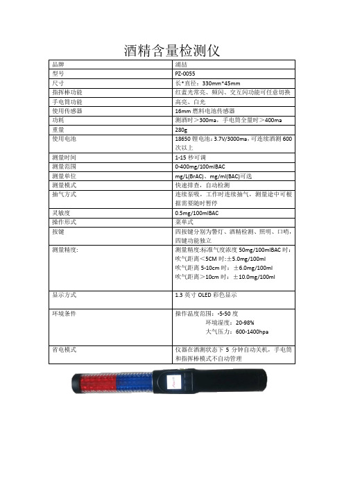
品牌
浦喆
型号
PZ-0055
尺寸
长*直径:330mm*45mm
指挥棒功能
红蓝光常亮、频闪、交互闪功能可任意切换
手电筒功能
高亮、白光
使用传感器
16mm燃料电池传感器
功耗
测酒时>300ma,手电筒全量时>400ma
重量
280g
使用电池
18650锂电池:3.7V/3000ma,可连续酒测600次以上
测量精度:
测量精度:标准气度浓度50mg/100mlBAC时:
吹气距离<5CM时:±5.0mg/100ml
吹气距离5-10cm时:±6.0mg/100ml
吹气距离>10cm时:±10.0mg/100ml
显示方式
1.3英寸OLED彩色显示
环境条件
操作温度范围:-5-50度
环境湿度:20-98%
大气压力:600-1400hpa
测量时间
1-15秒可调
测量范围
0-400mg/100mlBAC
测量单位
mg/L(BrAC)、mg/ml(BAC)可选
测量模式
快速排查,自量途中可根据需要随时暂停
灵敏度
0.5mg/100mlBAC
操作形式
菜单式
按键
四按键分别为警灯、酒精检测、照明、口哨,四键功能独立
省电模式
仪器在酒测状态下5分钟自动关机,手电筒和指挥棒模式不自动管理
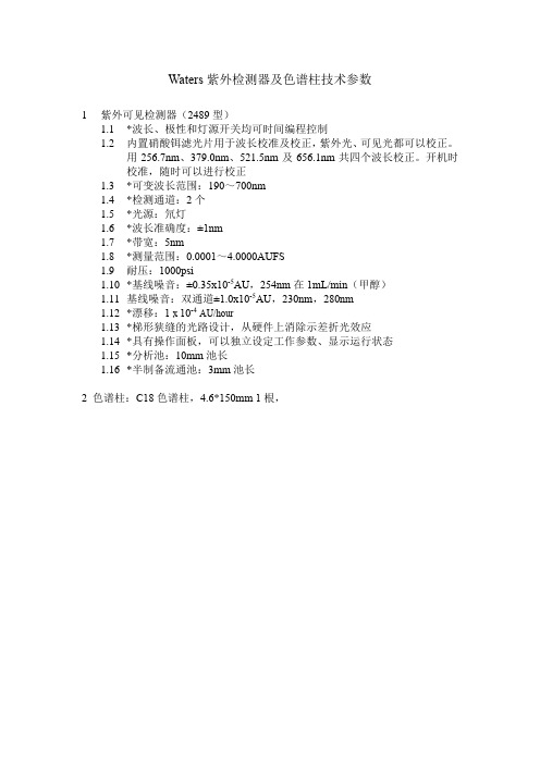
Waters紫外检测器及色谱柱技术参数
Waters紫外检测器及色谱柱技术参数
1紫外可见检测器(2489型)
1.1*波长、极性和灯源开关均可时间编程控制
1.2内置硝酸铒滤光片用于波长校准及校正,紫外光、可见光都可以校正。
用256.7nm、379.0nm、521.5nm及656.1nm共四个波长校正。
开机时
校准,随时可以进行校正
1.3*可变波长范围:190~700nm
1.4*检测通道:2个
1.5*光源:氘灯
1.6*波长准确度:±1nm
1.7*带宽:5nm
1.8*测量范围:0.0001~4.0000AUFS
1.9耐压:1000psi
1.10*基线噪音:±0.35x10⁻⁵AU,254nm在1mL/min(甲醇)
1.11基线噪音:双通道±1.0x10⁻⁵AU,230nm,280nm
1.12*漂移:1 x 10⁻⁴AU/hour
1.13*梯形狭缝的光路设计,从硬件上消除示差折光效应
1.14*具有操作面板,可以独立设定工作参数、显示运行状态
1.15*分析池:10mm池长
1.16*半制备流通池:3mm池长
2 色谱柱:C18色谱柱,4.6*150mm 1根,。
8902F1 8904F 数字电参数测量仪 使用说明书
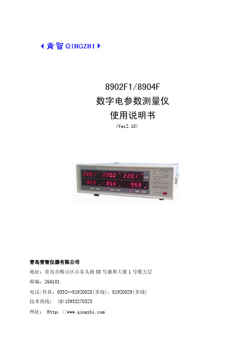
8902F1/8904F数字电参数测量仪使用说明书(Ver2.10)青岛青智仪器有限公司地址:青岛市崂山区山东头路58号盛和大厦1号楼五层邮编:266101电话/传真:0532--81920028(多线),81920029(多线)技术热线:(0)139****0323网址: Http://目录第一章 概述 (1)第二章 主要技术参数 (2)第三章 仪器使用说明 (3)一、前面板说明 (3)二、按键功能介绍 (4)三、参数测试说明 (6)四、后面板及接线图 (6)第四章 串口通讯 (8)第五章 仪器装箱清单 (8)第六章 注意事项及故障排除方法 (9)第一章 概述8902F1/8904F数字电参数测量仪是一种利用单片机技术对信号进行分析处理的智能型仪表。
它的工作原理是:被测量的电压、电流信号首先变换成较小的电压信号,送到高速模拟数字转换器,使之转换成单片机可以处理的数字量。
单片机对采集到的数字量进行运算处理,并将最终计算的结果以数字的形式显示出来,或以串行通讯形式将数据传送给其他设备。
与传统指针式仪表相比,数字电参数测量仪具有以下优点:1.所测信号数值为真有效值。
2.直接数字显示,无读数误差。
3.对于波形失真的信号同样适用。
4.用一台仪器可以测量多个参数。
数字电参数测量仪广泛应用于电机、变电站、发电厂等测试。
仪表型号与功能的对应关系如下表所示:表1 仪表规格型号对照表型号电压、电流、有功功率、频率、功率因数电能累计RS232/RS4858902F1 √ⅹ可选8904F √ √标配RS232/ 可选RS485说明:接线方式---仪表允许的测试接线方式。
不同的接线方式对合计数据的影响见表5。
接线方式的选择依据用户的被测试设备的供电方式,或用户测试需要。
注意仪表检定时:1.电压倍率和电流倍率必须均设为1。
2.线制为三相四线,仪表接线请参照三相四线接线图。
第二章主要技术参数数字电参数测量仪的测试对象为(45~65)Hz交流信号,具体技术参数如下:1.主要技术参数:表2 数字电参数测量仪主要技术指标测量参数 测量范围 测量误差 分辨力电 压 10.0 ~ 500.0单位:V±(0.4%读数+0.1%量程) < 0.1*量程±(0.16%读数+0.04%量程) ≥0.1*量程0.1 V电 流 0.03 ~ 40.0单位:A±(0.4%读数+0.1%量程) < 0.1*量程±(0.16%读数+0.04%量程) ≥0.1*量程0.001A < 5A0.01A ≥5A有功 功率 视电压电流量程而定额定电压380V±(0.16%读数+0.04%量程) PF=1.0±(0.8%读数+0.2%量程) PF=0.50.1W <200W1W <2000W10W ≥2000W功率因数0.05~1.00 ±0.02 额定电压380V 0.01频 率 (45~65)Hz ±0.1Hz 0.1Hz以下功能仅针对8904F电 能 9999.9 MWhPF=1.0: ±(0.16%读数+0.04%量程)PF=0.5:±(0.8%读数+0.2%量程)5位数显示时 间1min~99h59min±0.05% 1分钟注1: 电压、电流允许过载为1.2倍量程上限值。
HP8920/8921使用说明
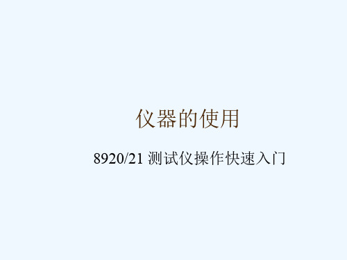
如何使用频谱分析仪的点
在“”下选择 在“”下设置不同的数值可手动的调节 点 在“ ”下选择和 ,可在最高峰和其他波 峰之间切换 可自动将点移至中心频率, 可自动调节参考功率
如何设置频谱分析仪的扫频发生器
在“”下选择 在选中 在“”下设置扫频的信号功率 在“”下选择信号输出端口 ,并设置扫 频方向
如何输出一个正弦音频
如何选择输出正弦,方波,三角波以及 锯齿波
如何输出一个正弦音频
在面板上按下按键“”进入起始 界面 连接 端口 在“1 ”下设置音频频率 在“1 ”下设置音频幅度 即可得到所需的正弦音频信号 如下图所示
如何选择输出正弦,方波,三角波以及锯齿 波
选择“ ”中的 在“”选择 在“2 ”中输入需要的频率 在“”中选择波形,如正弦,方波,三 角波等等 在“2 ”中选择输出方式 输入需要的音频幅度 即可
如何测量音频失真 如何测量音频频率 如何测量音频幅度
如何测量音频失真
测量解调音频失真 在面板上按下按键“”进入起始 界面 连接仪器并发射调制射频信号 在“ ”下选择即可显示解调音频的失真
度 测量音频失真 在面板上按下按键“”进入起始 界面 将音频信号与端口 连接 在“”下选择即可显示输入音频的失真度
如何测量音频频率
测量解调音频频率 在面板上按下按键“”进入起始 界面 连接仪器并发射调制射频信号 在“ ”下选择 即可显示解调音频的频率 测量音频失真 在面板上按下按键“”进入起始 界面 将音频信号与端口 连接 在“”下选择 即可显示输入音频的频率
如何测量音频幅度
在面板上按下按键“”进入起始 界面 将音频信号与端口 连接 音频幅度即显示在“ ”下 注:在所有的音频测试前,应检查仪器的滤 波器设置状态,必须保证所测试的信号频率 在滤波器通带之内,才能得到准确的数据
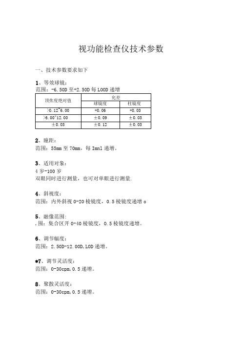
视功能检查仪技术参数
双眼同时进行测量,也可对单眼进行测量.
4、斜视度:
范围:内外斜视0-20棱镜度,0.5棱镜度递增o
5、融像范围:
,围:集合区开0-40棱镜度,0.5棱镜度递增。
6、调节幅度:
范围:2.50D-12.00D,LOD递增。
*7、调节灵活度:
范围:0-30cpm,0.5递增。
8、聚散灵活度:
视功能检查仪技术参数
一、技术参数要求如下
1、等效球镜:
范围:-6.50D至+2.50D每LOOD递增
顶焦度绝对值
允差
球镜度
柱镜度
>0.12~6.00
+0.06
+0.03
>6.00"12.00
±0.09
±0.03
±0.03
±0.12
±0.03
2、瞳距:
范围:55mm至70mm,每Imnl递增。
3、适用对象:
范围:0-30cpm,0.5递增。
9、立体视锐度:范围:40"-7200'o
*10、电子病历:
具有电子病例报告,具备患者数据库,记录患者数据,可实现数据导入导出;可打印报告。
二、设备配置清单
序号
设备配件
数量
1
额拖
1
2
Hale Waihona Puke 颌拖13电源线
1
4
颌拖支架
1
5
机头机身连接架
2
6
pad支撑架
2
7
Z型板
1
8
升降台架
1
序号
设备配件
数量
9
升降台板
1
10
酒精检测仪标准参数
酒精检测仪标准参数酒精检测仪是一种广泛应用于法律执法、交通管理、企业安全管理以及个人自测等领域的重要设备。
其准确性和稳定性对于保障公共安全和司法公正具有重要意义。
为了确保酒精检测仪的准确性和可靠性,制定和遵守相关的标准参数显得尤为重要。
本文将围绕酒精检测仪的标准参数展开详细探讨,以期对相关工作提供一定的参考和借鉴。
一、标准参数的意义酒精检测仪的标准参数是指在制定、测试和使用该设备过程中所需遵循的一系列规范指标。
这些参数的设定,旨在确保酒精检测仪能够准确、稳定地检测出被测对象体内的酒精浓度,并且确保检测结果具有法律效力。
这些参数的制定,可以有效提高酒精检测仪的检测准确性和可靠性,从而为社会的安全和公正提供保障。
二、标准参数的内容1. 准确性:酒精检测仪的准确性是指其检测结果与实际浓度的偏差。
通常采用误差百分比或误差值来表示。
国际上通常规定酒精检测仪的准确性应在合理的范围内,一般不超过5%。
在设计和制造酒精检测仪时,需要对其检测准确性进行严格的测试和验证,以确保其符合相关标准。
2. 稳定性:酒精检测仪的稳定性是指其在长时间使用过程中,检测结果的变化情况。
稳定性是保证酒精检测仪长期可靠运行的重要指标。
一般来说,酒精检测仪在规定的时间范围内,其检测结果变化应在规定范围内,不应超过一定的误差值。
3. 灵敏度:酒精检测仪的灵敏度是指其对酒精浓度变化的检测能力。
在设计和制造酒精检测仪时,需要注意其对不同浓度酒精的检测能力,确保其具有足够的灵敏度。
还需要规定其在不同温度、湿度等环境条件下的灵敏度变化情况。
4. 反应时间:酒精检测仪的反应时间是指其从开始检测到给出结果所需的时间。
反应时间的长短直接影响到酒精检测仪的使用效果,一般而言,反应时间应尽量缩短,以提高检测的实时性和准确性。
5. 温度和湿度影响:酒精检测仪在不同温度和湿度条件下的检测准确性和稳定性也是重要参数。
温度和湿度的变化会对酒精检测仪的工作产生影响,因此需要对其在不同环境条件下的适应性进行测试和规定。
测试仪参数说明书

Parameters Measured: Measurement Circuit Mode:Displays:Measurement Terminals: Ranging Mode:Test Frequency:Freq Accuracy: Measurement Rate:Test Signal Level: Response Time:Temperature Coefficient:Operation Temperature: Storage Temperature:10M 9.999M 1M 999.9k 100k 99.99k 10k 9.999k 1k 999.9100k 99.99109.999ΩΩΩΩΩΩΩΩΩΩΩΩΩNOTES:1. This specification is based on the measurement performed at the test socket2. DUT & Test lead to be properly shielded to GND (DC "-") if necessary.3. This specification is based on internal power (battery) operation.Resistance ΩPower Requirements1) Battery: DC 9V Battery2) Ext. DC Adaptor: DC 12Vmin-15Vmax (LOAD 50mA min)Low Battery Indication : Approx. 6.8VPower Consumption: Approx. 40 mA; 0.3mA Auto Power-offProtective Fuse: 0.1A fast-blow 250V AC (Pleaserefer to Safety Information)Auto Power-Off Time: Approx. 5 mins.Dimensions: 37 mm(H) x 90 mm(W) x 192(L)Weight: 390gStandard Accessories: Test alligator clips (pair), battery (DC 9V), spare fuse (0.1A/250V AC fast-blow)and operator manualElectrical Specifications All accuracies are @ 23°C; <75% R.H.±(0.5%+5 counts)±(0.5%+3 counts)±(0.5%+3 counts)±(0.5%+3 counts)±(0.8%+5 counts)±(1.2%+8 counts)±(2%+8 counts) *(note 3)Test Freq. 1KHz ±(2%+8 counts) *(note 3)±(0.5%+5 counts)±(0.5%+3 counts)±(0.5%+3 counts)±(0.5%+3 counts)±(0.8%+5 counts)±(1.2%+8 counts)Specified Note after open cal.after open cal.after short cal.after short cal.AccuracyTest Freq. 120HzDF 10mF9.99mF (note 4)A (5% + 5 counts) (DF<0.1)A (10% + 100/Cx + 5 Counts) (DF<0.1)1000µF999.9µF A (1% + 5 counts) (DF<0.1)A (2% + 100/Cx + 5 Counts) (DF<0.1)100µF99.99µF 10µF9.999µF 1000nF999.9nF 100nF99.99nF A (0.7% + 5 counts) (DF<0.5)A (0.7% + 100/Cx + 5 Counts) (DF<0.5)10nF 9.999nF A (1% + 5 counts) (DF<0.1)A (2% + 100/Cx + 5 Counts) (DF<0.1)DF 1000µF0.999mF A (5% + 5 counts) (DF<0.1)A (10% + 100/Cx + 5 Counts) (DF<0.1)100µF99.99µF A (1% + 5 counts) (DF<0.1)A (2% + 100/Cx + 5 Counts) (DF<0.1)10µF9.999µF 1000nF999.9nF 100nF99.99nF 10nF9.999nF 1000pF 999.9pF A (1% + 5 counts) (DF<0.1)A (2% + 100/Cx + 5 Counts) (DF<0.1)Specified Note after short cal.A (0.7% + 3 counts) (DF<0.5)A (0.7% + 100/Cx + 5 Counts) (DF<0.5)after open cal.Test Frequency: 120HzTest Frequency: 1kHzRangeMax. Display Accuracy A (0.7% + 3 counts) (DF<0.5)A (0.7% + 100/Cx + 5 Counts) (DF<0.5)after short cal.after open cal.RangeMax. Display Accuracy Specified Note NOTES:1. Q value is the reciprocal of DF2. This specifiction is based on the measurement performed at the test socket3. Dut & test lead to be properly shielded to GND (DC "-") if necessary4. This reading can be extended to 1999 MAX display with accuracy not specified5. Cx = Counts of displayed C value e.g. C=88.88µF then Cx=8888Capacitance(note 4)(DF<0.5)(0.7% + 5 counts) Cx (Note 5)Cx (Note 5)DF (DF<0.5)10000H9999H Note 4Note 4- - - - 1000H999.9H A [1% + (Lx/10000)% +5 counts]A (2% + 100/Lx + 5 Counts)after open cal.100H99.99H - - - -10H9.999H - - - -1H999.9mH - - - - 100mH99.99mH A [1% + (Lx/10000)% +5 counts]A (3% + 100/Lx + 5 Counts)10mH 9.999mH A [2% + (Lx/10000)% +5 counts]A (10% + 100/Lx + 5 Counts)DF (DF<0.5)1000H999.9H Note 4Note 4- - - -100H99.99H A [1% + (Lx/10000)% +5 counts]after open cal.10H9.999H - - - -1H999.9mH - - - -100mH99.99mH - - - - 10mH9.999mH A [1.2% + (Lx/10000)% +5 counts]A (5% + 100/Lx + 5 Counts)1mH 999.9µH A [2% + (Lx/10000)% +5 counts]A (10% + 100/Lx + 5 Counts)A [0.7% + (Lx/10000)% +5 counts]A (1.2% + 100/Lx + 5 Counts)after short cal.RangeMax. Display Accuracy Specified Note A [0.7% + (Lx/10000)% +5 counts]A (1.2% + 100/Lx + 5 Counts)after short cal.Test Frequency: 1KHz Test Frequency: 120Hz RangeMax. Display Accuracy Specified Note NOTES:1. Q value is the reciprocal of DF2. This specifiction is based on the measurement performed at the test socket3. DUT & test lead to be properly shielded to GND (DC "-") if necessary4. Not specified5. Lx = Counts of displayed L value e.g. L=88.88µF then Lx=8888InductanceLx (DF<0.5) (Note 5)Lx (DF<0.5) (Note 5)。
东联智通便携式酒精测试仪工作原理解析

东联智通便携式酒精测试仪工作原理解析
我们经常在电视新闻中看到交警查酒驾时,只需要拿着检测仪要求司机吹气就能查出,那么这到底是什么原理呢?下面给大家解析一下东联智通酒精检测仪的工作原理。
当具有N型导电性的氧化物暴露在大气中时,会由于氧气的吸附而减少其内部的电子
数量而使其电阻增大。
其后如果大气中存在某种特定的还原性气体,它将与吸附的氧
气反应,从而使氧化物内的电子数增加,导致氧化物电阻减小。
半导体氧化物传感器
就是通过该阻值的变化来分析气体浓度。
根据国家质量监督检验检疫局发布的《车辆驾驶人员血液、呼气酒精含量阈值与检验》(GB19522—2004)中规定,该规定指出,饮酒驾车是指车辆驾驶人员血液中的酒精含
量大于或者等于20mg/100ml,小于80mg/100ml的驾驶行为。
醉酒驾车是指车辆驾
驶人员血液中的酒精含量大于或者等于80mg/100ml的驾驶行为。
不过在检查醉酒驾车时,交警使用的便携式酒精检测仪只能进行初步判断,有醉驾嫌疑的驾驶员还需要接受血检,以确定其体内酒精含量是否超标。
博特(连云港)仪器有限公司 SXJC-II(A) 台式酒精检测仪 使用说明书
博特(连云港)仪器有限公司地址:中国。
江苏。
连云港电话:400-828-9920网址: 台式酒精检测仪使用说明书博特(连云港)仪器有限公司Bote(Lianyungang)Instrument Co.,LTD一、简介SXJC系列测酒仪是专用于司乘工作人员出退勤测酒管理的仪器,本机具有极好的灵敏度和出色的重复性,使用方便,显示直观清晰,可自动报警,联网测试并记录测试结果。
本机兼容各版本运用管理软件,可与指纹数据同步,确保测试过程的准确性。
本机配套专用《出退勤测酒管理系统》,自动判断只张口不吹气、吹气不足,并可录像测试过程,防止替测。
二、图示(下为示意图,不同机型以机壳标识为准)后面板连接图:注:若摄像头为370型,请直接将其连接到电脑USB口即可。
1、使用前的通电检查:请确保电源插座有可靠接地把电源插头插入220V市电插座,电源线另一端插入测酒仪后面的电源插座,电源指示灯亮。
2.连接计算机:串口通讯线两端分别连接到测酒仪器的接口和计算机的RS232口。
请注意不可带电拔插数据线!3.开机预热:将电源开关置于“开”(ON),电源指示灯亮,约60秒后“就绪“指示灯点亮,可以进行检测。
长期储存后首次开机请在上电10分钟后使用以保证最高精度。
4.检测:A开启计算机端的《出退勤测酒管理系统》B在通过键盘输入工号(或在指纹仪上按预留指纹),屏幕提示“姓名,工号,点击选择按钮,选择“出勤”、“退勤”、“签到”或其他对应选项后点击“确定”按钮,并提示“开始吹气测酒”,测酒仪“检测”指示灯亮,未连接电脑脱机独立使用的机型省略B和C操作,只需等待测酒仪“检测”指示灯亮,方可吹气检测。
C确认计算机屏幕出现的姓名、工号正确D被检测者将嘴对准测酒仪器的检测杆头部的检测口正前,距离小于3CM,被检测者吸足气后再张口快速呼出肺内全部气体,呼气时间应该持续2秒钟。
注:若机器为JNX版,则支持不用输入工号,待就绪指示灯亮后,直接对准探头吹气即可进行检测。
ASD989 综合测试仪 用户使用手册说明书
©版权归属于昂盛达电子有限公司Ver1.6 /Nov, 2022/ ASD简介1.5安装位置1.6 外部启动接线图2&2:组1和组2的分配是: 开关SW1控制组1;开关SW2控制组2。
标准模式:SW1控制组1和组2;SW2控制组3和组4. 主要应用于外部启动,配合自动化测试的启动信号.接入产品工步上选输入选项设L或H,L表示低电平启动,H表示高电压启动.在某些情况下,用错误配置的市电电压为设备供电可能造成市电保险丝断开。
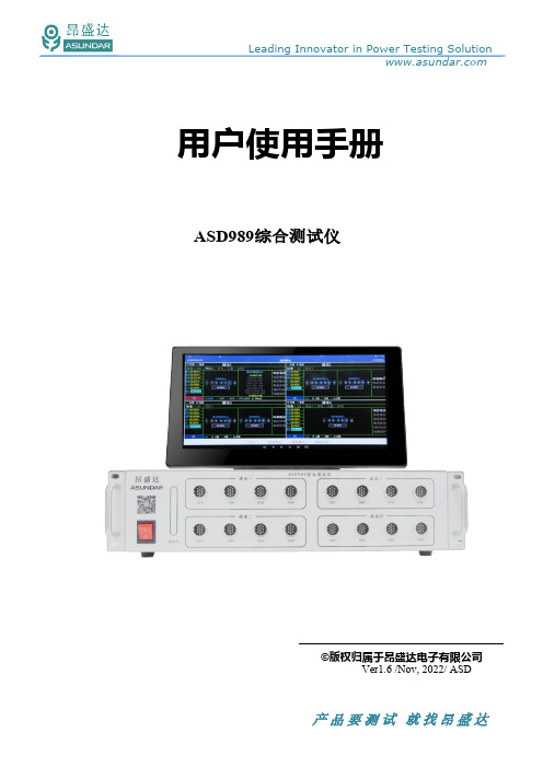
2.2 前面板介绍ASD989测试仪前面板除丝印外有设备名称、设备型号和厂家商标等信息外,设有图2.2 :ASD989前面板四路选配模拟电池外观图2.32.3 后面板介绍ASD989测试仪后面板除散热窗口外,设有AC电源输入插座,DC电源输出插座,通讯接口。
通讯接口DB9串口母座,232串口通迅,用于连接上位机进行数据通讯。
/IN2为输入外触发启动端口。
注:外壳的接口或外型有可能存在修改,差异.不另外通图ASD989后面板2.4触控屏介绍上位机采用Android-15.6寸高清液晶电容触摸屏设备,搭配专用软件,可视化操作并有音频提示。
支持WiFi、内置蓝牙、SIM卡和NET网口连接网络(开机5分钟后未连网或图2.4.1-ASD989安卓触控屏图4.1.1 研发模式4.1.1 PD模块电源模式支持标准、QC(2.0和3.0)和PD3.1协议。
负载模式支持标准QC2 ,PD3.1,三星AFC,华为(FCP,SCP,SSCP), VOOC等协议图4.1.2PD电源在PD电源模式有标准、QC、PD三种协议类型可选,如图4.1.2所示。
标准电源即无协议直流电源,可设置输出电压(0~48V)和输出电流(0~10A)。
并有的A面;B面;A+B面。
QC协议电源QC2.0有5V、9V、12V、20V电压可供选择,可设置最大允许电流(0~10A);QC3.0可设置协议电压及保护电流,协议电压按步进0.2V自动步进。
区食药方案
产品品牌型号参数农药残留检测仪(卡片机)农药残留检测仪(酶试剂)酒醇检测箱含酒醇仪和酒精度计、酒精对照样品、铝合金箱,用于检测酒中甲醇、乙醇含量。
酒醇仪技术参数:1.测量范围:0-80% V0L;2.最小刻度1%V0L;3.准确率±1%荧光增白剂测定仪1.依据行标:NY/T1257-20062.仪器箱体两侧设有双向操作口,前开门设计,方便取放样品3.通过数码相机微电脑控制,将样品传送到电脑,并对图像进行保存、分析4.用户可通过箱体直接观察到暗室内的样品5.特别设计防紫外线观察口,使操作人员避免紫外线损伤B2.0接口7.紫外短波波长:254nm8.紫外长波波长:365nm9.可见光源10.紫外滤色片尺寸:200×80mm11.工作电源: 220V交流电源12.使用温度: 0℃-40℃13.使用湿度: <90% (40℃)14.仪器功耗: 20W15.充电电压/电池容量 12.6V/9800mAH16.外型尺寸:300×200×290mm仪器特点1.采用微电脑进行控制,准确率高2.操作简单,无需专业人员3.检测速度快,1分钟出检测结果4.海量存储,可存储3000张以上图片B2.0接口6.体积小、重量轻、便于携带酒醇检测箱食用油品质检测仪水浴锅1.工作室水箱选材不锈钢,有优越的抗腐蚀性能。
2.控温精度高、数字显示、自动控温。
3.型式:单孔;电源:220V+10% 50HZ+2%。
4.功率:1000W。
5.控温范围室温-100℃范围内任意调节。
6.最大误差≤+1℃温度波动≤+0.5℃注水肉检测仪测量对象:猪、牛、羊、鸡等鲜肉水分测量范围:65—85%采样时间:一次采样时间<2S检测数据存储量: 1000组电源电压:9V(6F22层叠电池一节);功耗:约50mW仪器外型:约20mm x 9mm x 3.3mm 显示:3位液晶显示器(中文字符)使用环境温度:0℃—40℃使用环境湿度:20—90%RHA T P 荧光检测仪T D S 电导仪P H 计测距仪电子天平1.规格:200g/0.001g。
关于指挥棒式酒精检测仪的功能特点介绍 检测仪操作规程
关于指挥棒式酒精检测仪的功能特点介绍检测仪操作规程指挥棒式快速酒精检测仪,不用吹气,自动抽气,连续检测。
白天可以当警示指挥棒使用,晚上也可以当手电筒使用,是一款多功能专用酒精检测仪。
指挥棒式酒精检指挥棒式快速酒精检测仪,不用吹气,自动抽气,连续检测。
白天可以当警示指挥棒使用,晚上也可以当手电筒使用,是一款多功能专用酒精检测仪。
指挥棒式酒精检测仪的功能特点1、检测探头:接受电化学燃料电池。
2、按键功能:中文按键,“测试”一键式完成操作,简单快捷。
3、屏幕显示:彩色 oled显示屏,在强光也很清楚,酒精测试过程在屏幕上动态显示,便利。
4、震动马达提示功能:当测试结果低于国家标按时,震动马达不震动,指示灯不工作业;当测试结果高于国家标按时,震动马达发出震动提示,指示灯不闪亮,可让检测人与被检测人适时了解检测结果有无酒精情况。
5、快速排查检测:接受电机循环抽气采样,被测人只要靠近进气口哈气,就能自动采样分析,无须手动按键采样。
检测快速,1秒出结果。
6、定性检测:具备定性检测功能,为确保的公正与精准性,其定性测试结果用数据直观显示。
7、采样品:接受凹面式采样口设计,具有导向、收集气体功能。
8、不用预热时间:开机直接测试。
9、电源:节能设计,本机接受可充锂离子电池,容量2200mah,可连续工作8小时。
10、设备外观尺寸、重量:符合人体工程学棒式设计,携带便利。
11、手电模式:便利夜晚。
紧要参数:传感器类型:取模式:电池燃料电化学酒精传感器快排模式:半导体酒精传感器测量范围:取模式:0——440mg/100ml(0——2.000mg/L)快排模式:0——220mg/100ml(0——1.000mg/L)预热时间:15s响应时间:不到1秒采样方式:取模式:定量采集分析快排模式:气泵泵吸,自动连续抽气连续工作时间:数百次——两千次(与电池电量有关)主机尺寸:LxH(mm):293x41.3x40.7主机重量:约600g(带1节电池,锂电池)校准周期:180天传感器工作寿命:两年—专业分析仪器服务平台,试验室仪器设备交易网,仪器行业专业网络宣扬媒体。
- 1、下载文档前请自行甄别文档内容的完整性,平台不提供额外的编辑、内容补充、找答案等附加服务。
- 2、"仅部分预览"的文档,不可在线预览部分如存在完整性等问题,可反馈申请退款(可完整预览的文档不适用该条件!)。
- 3、如文档侵犯您的权益,请联系客服反馈,我们会尽快为您处理(人工客服工作时间:9:00-18:30)。
东联智通WAT89-EC6酒检仪参数信息
东联智通WAT89-EC6酒检仪是一款便携式酒精检测仪,它主要用于煤矿单位,它主要的特点就是简便快捷,每一个矿工在下井作业时只需要对着它吹气就能快速的测出体内酒精是否超标,对于岗前饮酒监督来说十分便利。
以下是它的参数信息以及具体介绍。
产品型号:WAT89-EC6
传感器:燃料电池型电化学
预热时间:0s
感应时间:3s-12s
回复时间:30s
测量范围:0mg/L-1.5mg/L
测量精度:±0.025mg/L
抗干扰性:对非酒精类气体不反应
特点:两种吹气方式,电化学探头,联网通讯,工号记录。
功能指标:
传感器:电化学传感器(警用标准)
吹起方式:非接触式吹筒或一次性吹管
录入方式:触摸屏
存储容量:3000条
通讯方式:USB
显示方式:液晶屏
报警:声光报警
供电方式:锂电池(或7号AAA干电池)
喇叭形吹口:便携式酒精检测仪喇叭形吹口安装与酒精检测仪顶部,无需对嘴吹气,非接触式吹气吹口,可长期使用,方便清洗。
吹管型吹口:便携式酒精检测仪吹管形吹口安装于酒精检测仪顶部,用户对准吹口吹气,可进行快测和强测两种测试,进行精准测试。
吹管吹口为一次性用品。
