sas9.4最新sid 2017年
NVIDIA显卡
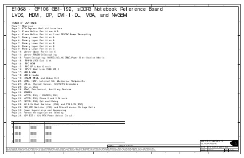
Page 12: Power/Decoupling: NVVDD,3V3_NV,GRND,Power Distribution Matrix
Page 13: IFPA/B LVDS Dual Link
Page 14: IFPC HDMI
Page 15: IFPD DP & Aux Circuit
Page 16: IFPE/F Dual Link TMDS DVI-I
Page 27: FBVDD (PS3) Optional/Debug
Page 28: 5V/3.3V Dual Switcher (PS4) and 1V8 LDO (PS7)
4
Page 29: PEX_VDD Switcher (PS5) and Miscellaneous Voltage Rails
A
B
C
D
E
F
G
H
1
2
3
4
5
NVIDIA CORPORATION
2701 SAN TOMAS EXPRESSWAY
SANTA CLARA, CA 95050, USA
NV_PN 600-11068-0000-000
PCB REV BOM REV
E1068-A00 B
PAGE 1 OF 32 DATE 17-FEB-2010
Page 30: Power Supervision and Sequencing
Page 31: Remote Voltage/Current Sensing
Page 32: 12V EXT / 12V PEX Power Select Circuit
SKU VARIANT
B BASE
GE系统简介(sis)
GE Fanuc 不仅仅是一个自动化产品的供应商,更是满足不 同客户需求的方案提供者。我们为客户提供良好的物流保 障和随时可及的售前、售后服务。更重要的是,我们的自 动化专家为您提供专业的项目咨询,从而确保您的自动化 系统是最优化的。
GE Fanuc 总部位于美国弗吉尼亚州夏洛茨韦尔,是 GE 工业系统集团的一部 分,它将 GE 家族广泛的全球性优势与满足本地的用户需求相结合,设计、开 发并维护用户在自动化方面的投资。
GE Fanuc 亚太公司业务遍及整个亚太地区,包括中国、韩国、日本、东南亚、 西亚和大洋洲。位于上海的亚太地区业务总部为这些地区提供市场、客户服 务、财务、订单处理和发货管理等服务。
GE Fanuc 公司介绍
GE Fanuc 公司介绍
GE Fanuc 公司由美国通用电气公司(GE)和日本 Fanuc 公司合资组建,提供自 动化硬件和软件解决方案,帮助用户降低成本、提高效率并增强其盈利能力。 凭藉适合于几乎每种工业门类的解决方案和服务,GE Fanuc 提供多样化的产品 和服务,范围包括控制器、嵌入式系统、高端软件、运动控制产品、操作员界 面产品、工业计算机和激光设备。
在 SIS 系统中为了提高可靠性,可以配置冗余历史数据库 服务器,将两台互为冗余的历史数据服务器通过双网冗 余星形拓扑结构以太网与电厂各生产系统进行通讯,读 取所有子系统的信息,形成 SIS 的历史数据数据库。
应用报表和数据分析部分是 SIS 系统应用集成功能计算分 析的核心,这部分功能同样要结合 MIS进行集成开发, 结 果 的 发 布 和 表 现 形 式 则 可 通 过 WEB服务器集中发布 完成。Proficy Real Time Information Portal 企业信息 门户技术(简称 RTIP),负责将 SIS 应用与 MIS 应用集成 为统一信息发布平台,所有生产实时信息可通过 RTIP 服 务器发布到厂级的管理信息网络上,供给厂长、总工及 生产科室等厂级用户浏览、分析。
SAS Foundation 9.4安装快速指南说明书

Quick guide for SAS® Foundation 9.4 Installation1.Before you begin installing the SAS software, ensure that there are no antivirus or firewall servicesrunning on the machine. Check Windows Services by doing the following:Select Start ► Run and type services.msc. For Windows 7, type services.msc in the Search programs and files search box.Look for any antivirus software that is in a started state. Stop the services by clicking Stop in the upper left corner.Some of the antivirus software programs that you might see under the Services window include but are not limited to Norton, Symantec, McAfee, Trend, Microsoft, VIPRE, Kaspersky, and AVG.Here is an example of what you might see in the Services window. Note that there is usually one antivirus service that you are unable to stop. That is fine. The problem is if you cannot stop any of the services. In that case, contact your IT department to stop these for you while you are performing the installation. Alternatively, have an Administrator log on and do the installation for you.2.SAS Deployment Wizard manages the SAS Foundation Deployment.To start, Browse to your SAS depot folder and Right click on setup.exe. Then click on “Run asadministrator”.3.Select your preferred language for the SAS Deployment Wizard.4.Select Deployment Task — Select Install SAS Software. Click Next.5.If prompted, Select the correct SAS order.. Click Next. Otherwise, Specify SAS Home — Choose a filesystem location for the home folder for your SAS software. This will default to C:\ProgramFiles\SASHome. You can use the Browse button to navigate to an alternate location for your SAS Home. Click Next.6.Select Deployment Type — Select Install SAS Foundation and Related Software. Click Next.7.Select Products to install — Click on Clear All. Then select both SAS Enterprise Guide and SASFoundation. Click Next.**Note: It is recommended to tick SAS PC-Files sever if you are installing on 64bit windows for enhanced access to Microsoft Windows-specific data files, such as Microsoft Excel andMicrosoft Access.8.Select SAS Foundation Products — The defaults that are selected are all of the SAS Foundationproducts in your order. Generally, you will want all of the products in your order. Click Next.9.Specify SAS Installation Data File — This is the path to your SID file. By default, the SID file islocated in the sid_files folder of your SAS Software Depot. If necessary, click Browse to navigate to this file. Click Browse.10.Select Language Support — Select the languages that you want to install for the products that arelisted. Only those languages that work with your locale are installed. Click Next.**Clicking on “Clear all” will only leave English ticked.11.Select Regional Settings. — Select the Locale. For ex: English (Australia) [en_AU]. Click Next.12.Select the default product for SAS file Types. Click Next.** The default selection is SAS Foundation.13.Checking System — The SAS Deployment Wizard checks to ensure that the system has enough diskspace and the files and folders that it will write are accessible. The installation cannot proceed until access is granted for any listed files. When the examination is complete, click Next.14.Deployment Summary — Click on start to begin the installation.15.Deployment Complete — Check all stages for errors or warnings. Click Next.16.Select support Option — Select to send an electronic record to SAS if you wish. Click Next.17.Additional Resources — Record these links for future reference. Click Finish.If you have any technical issues, You can contact SAS Australia Technical support through the channels below.CONTACT INFORMATION•/ctx/supportform/createForm•**************.com•AustraliaPhone: +61-2 9428 0444Fax: +61-2 9418 72998.30am to 5.30pm (EST)BE PREPARED!Please provide us with the following:•Site Number•Operating System•Current Software Release•Full details of any error message and SAS log.。
网神SecFox安全管理系统快速指南5.9.4.X(软件)[V16.5.1]
![网神SecFox安全管理系统快速指南5.9.4.X(软件)[V16.5.1]](https://img.taocdn.com/s3/m/3f106419bed5b9f3f90f1c26.png)
网神SecFox安全管理系统快速指南声明服务修订:●本公司保留不预先通知客户而修改本文档所含内容的权利。
有限责任:●本公司除仅就产品信息预先说明的范围承担责任,无论明示或默示,不作其它任何担保,包括(但不限于)本手册中推荐使用产品的适用性和安全性、产品的适销性和适合某种特定用途的担保。
●本公司对于您的使用或不能使用本产品而发生的任何损坏不负任何赔偿责任,包括(但不限于)直接的、间接的、附加的个人损害、商业损失或任何其它损失。
版权信息:●任何组织和个人对本公司产品的拥有、使用以及复制都必须经过本公司书面的有效授权。
网神信息技术(北京)股份有限公司北京市海淀区上地开发区开拓路7号先锋大厦目录第1章系统概述 (5)1.1系统功能 (5)1.2系统功能 (6)1.3产品形态 (6)1.4相关参考手册 (7)1.5公司地址 (7)第2章安装与卸载 (8)2.1安装光盘内容 (8)2.2安装服务器 (8)2.3卸载服务器 (8)第3章如何开始 (10)3.1启动服务器 (10)3.2登录系统 (10)第4章设备配置 (12)4.1设备监控协议配置 (12)4.1.1网络设备 (12)4.1.2安全设备 (13)4.1.3 SecGate安全网关 (13)4.1.4 Windows主机设备 (13)4.1.5 Unix主机设备 (14)4.1.6 Weblogic (15)4.1.7 Websphere (16)4.1.8 Tomcat (17)4.1.9 WebsphereMQ (18)4.1.10 Lotus Domino (18)4.1.11 IIS (20)4.1.12 Oracle数据库 (20)4.1.13 MSSQL数据库 (21)4.1.14 MYSQL数据库 (21)4.1.15 DB2数据库 (22)4.1.16 Sybase数据库 (22)4.2事件源配置 (23)4.2.1有发送功能的设备 (23)4.2.2没有发送功能的设备 (25)4.3开放端口 (26)第5章系统配置 (27)5.1服务器配置 (27)5.2采集参数配置 (28)5.3数据的备份归档设置 (29)5.4安装W INDOWS事件传感器 (29)5.5资源定义 (29)5.5.1时间资源 (29)5.5.2地址资源 (30)5.5.3端口资源 (30)5.6过滤器 (30)第6章开始使用 (32)6.1如何查看整体网络状况 (32)6.1.1网络拓扑发现 (32)6.1.2网络监控与管理 (32)6.1.3物理拓扑-机架视图 (33)6.2如何监控设备和应用的运行情况 (33)6.2.1建立监控任务 (33)6.2.2配置告警规则 (33)6.3如何监控业务的运行状态 (34)6.3.1建立业务 (34)6.3.2查看业务运行状态 (34)6.4如何进行日志审计 (34)6.4.1如何实时监视日志 (34)6.4.2如何实时分析日志 (35)6.4.3如何查询历史日志 (36)6.4.4如何对日志进行趋势分析 (36)6.5如何配置关联告警规则 (36)6.6如何创建适合自己的视图 (37)6.7如何生成报表 (37)6.7.1系统内置报表 (37)6.7.2用户自定义报表 (38)6.7.3综合审计报告 (38)系统概述系统功能SecFox安全管理系统能够统一管理企业和组织的各类基础设施节点,包括网络、安全、存储、主机等设备,以及机房供电、环境和安防等系统。
sas接口发展历程
sas接口发展历程SAS(Serial Attached SCSI)接口是一种用于连接计算机系统和外部存储设备的接口标准。
它是在传统的SCSI接口基础上发展而来,旨在提供更高的数据传输速度和更大的存储容量。
SAS接口的发展历程可以追溯到2004年,以下是SAS接口的主要发展阶段。
第一阶段(2004年):SAS 1.0SAS 1.0于2004年发布,定义了初版的SAS接口标准。
SAS 1.0基于传统的SCSI接口,并引入了一些新技术,例如点对点连接和高速序列数据传输。
SAS 1.0支持单通道和双通道配置,每个通道的数据传输速率为3 Gbps。
第二阶段(2007年):SAS 2.0SAS 2.0于2007年发布,是SAS接口的一次重大更新。
SAS 2.0在数据传输速率和存储容量方面取得了显著的提升。
它支持 6 Gbps的数据传输速率,并引入了更高的存储容量。
此外,SAS 2.0还支持端口间隔倍增(PAM)技术,可以通过增加相同数量的端口提高总体带宽。
第三阶段(2013年):SAS 3.0SAS 3.0于2013年发布,进一步提升了SAS接口的性能。
SAS 3.0支持12 Gbps的数据传输速率,是SAS 2.0的两倍。
它还引入了数据恢复和校验功能,提高了数据的安全性和可靠性。
此外,SAS 3.0还支持更高的存储容量和更多的通道配置,满足了不断增长的存储需求。
第四阶段(2016年):SAS 4.0SAS 4.0于2016年发布,代表了SAS接口的最新发展水平。
SAS 4.0支持24 Gbps的数据传输速率,是SAS 3.0的两倍。
它还引入了统一虚拟化支持和多链路皮连接技术,提供了更高的灵活性和可扩展性。
此外,SAS 4.0还支持更大的存储容量和更高的总线带宽。
未来发展趋势随着数据存储需求的不断增长,SAS接口将继续发展。
未来几年,我们可以期待更高的数据传输速率和更大的存储容量。
例如,SAS 5.0接口可能会支持48 Gbps或更高的数据传输速率,并提供更高的总线带宽和更大的存储容量。
WIN10(64位)系统安装SAS9.4图文教程
SAS9.4安装教程1.版本信息本文档主要介绍WIN10系统64位安装SAS9.4软件1.1.电脑操作系统●本机信息(OS):WIN10_64bit1.2.SAS版本●SAS9.4_64bit●安装文件夹:8G Framework3.5配置2.1.“启动或关闭windows功能” “控制面板”>“程序和功能”> Framework3.5下载安装●选择NET Framework 3.5,双击下载●安装NET Framework 3.53.SAS下载●网站下载:网络资源4.SAS安装4.1.下载包解压●SAS下载包16个●SAS下载包解压到同一文件夹SAS_9.4中4.2.系统日期设置●电脑系统日期设置至2014年3月14日之前一年内(2014年2月15日~2015年2月14日)。
●SID更新后,再将日期设置正常4.3.SAS安装向导Step1:打开文件夹,点击“setup.exe”,以管理员的身份运行Step2:安装启动,检查监视器参数4.4.SAS安装Step1:选择语言●选择“简体中文”,单击“确定”●根据需要选择,注意英文默认安装Step2:选择部署任务●默认:选择“安装SAS软件”,单击“下一步”Step3:指定SAS主目录●默认,单击“下一步”●可以自定义指定其他目录Step4:选择部署类型默认选择“安装SAS Foundation 和相关软件”,单击“下一步”Step5:选择要安装的产品●点击“全选”,安装全部产品,单击“下一步”●可以自定义选择所需的产品Step6:选择SAS Enterprise Guide模式●默认:选择“64位本机模式”,单击“下一步”●可以自定义选择“32位兼容模式”Step7:选择SAS Foundation 产品●默认:“全选”,单击“下一步”●可以自定义选择所需的SAS Foundation 产品Step8:选择SAS 安装数据(SID)文件●默认路径,单击“下一步”●SID显示有效期限2014年3月14日Step9:选择语言支持●默认:“英文”必选●建议选择“简体中文”,单击“下一步”Step10:选择区域设置默认:选择“中文(中国)[zh_CN]”,单击“下一步”Step11:SAS 文件类型的默认产品默认:选择“SAS Foundation(64位) ”,单击“下一步”Step12:指定SAS/GRAPH Java Aplet 部署目录●指定浏览器路径,谷歌:“C:\Program Files (x86)\Google\Chrome\Application”●IE浏览器:“C:\Program Files\Internet Explorer”●谷歌●IEStep13:指定SAS PC Files Server 系统服务选项●默认:选择“Windows启动时自动立即启动服务”,单击“下一步”●为提高电脑运行性能,取消勾选“Windows启动时自动立即启动服务”,使用前应先启动SAS服务Step13:指定SAS PC Files Server 端口●默认:端口号“9621”,单击“下一步”Step14:SAS 环境URL●设置:http://主机名:端口号/SASLogon/sas-environment.xml⏹http://Localhost:9621/SASLogon/sas-environment.xml●详细可见SAS●主机名:“此电脑”>“属性”>“计算机名、域和工作组设置”Step15:指定SAS Document Conversion 主机和端口●默认:端口号“7111”,单击“下一步”Step16:正在检查系统 检查开始检查中●检查结束Step17:部署汇总●单击“开始”●共计292个安装包Step18:正在部署●漫长的等待●“292. 安装后处理”安装失败,单击“确定”●Install post processingStep19:部署完成“安装后处理”显示“已完成但是有错误”,单击“下一步”Step20:选择支持选项默认:选择“不发送(D)”,单击“下一步”Step21:其他资源单击“完成”,完成安装5.SID更新5.1.SID下载 网络资源5.2.SID更新Step1:以管理员的身份运行“续订SAS软件(64-bit)”Step2:选择“SAS安装数据文件”●选择SID后,单击“下一步”Step3:“确认SAS安装数据”●单击“确定”Step4:选择“SAS安装数据文件”●单击“更新许可(R)”Step4:更新成功●单击“确定”,更新完成6.安装问题及解决方案6.1.SASHELP逻辑库连接问题6.1.1.错误信息WARNING: 连接逻辑库“SASHELP”中指定的一个或多个逻辑库不存在。
ITU-T G.8131
STUDY GROUP 15
TELECOMMUNICATION STANDARDIZATION SECTOR
STUDY PERIOD 2005-2008
TD 297 Rev1(PLEN/15)
English only Original: English
Document history Issue Notes
1.0
Initial version (date TSB)
ITU-T\COM-T\COM15\C\267E.DOC
-3TD297 Rev1 (PLEN/15)
CONTENTS 1 2 3 4 5 6 7 Scope ............................................................................................................................ 5 References..................................................................................................................... 5 Definitions .................................................................................................................... 5 Symbols and abbreviations ........................................................................................... 7 Conventions .................................................................................................................. 7 Network Objectives ...................................................................................................... 7 Architecture types ........................................................................................................ 8 7.1 T-MPLS trail protection ................................................................................. 8 7.1.1 1+1 trail protection ............................................................................................. 8 7.1.2 1:1 trail protection .............................................................................................. 9 7.2 T-MPLS SNC protection ................................................................................ 9 7.2.1 SNC/S protection ............................................................................................ 9 Switching types............................................................................................................. 9 Operation types ............................................................................................................. 9 9.1 Non-revertive operation.................................................................................. 9 9.2 Revertive operation ........................................................................................ 10 Automatic Protection Switching (APS) protocol ......................................................... 10 10.1 APS payload structure .................................................................................... 10 10.2 APS protocol type........................................................................................... 11 Application architectures .............................................................................................. 12 11.1 Unidirectional 1+1 trail protection switching................................................. 12 11.2 Bidirectional 1:1 trail protection switching .................................................... 13 11.3 11.4 12 Unidirectional 1+1 SNC/S protection switching .......................................... 14 Bidirectional 1:1 SNC/S protection switching ............................................... 14
sas 9.4 x64 破解文件

'PRODNUM538' 'PRODNUM550' 'PRODNUM555' 'PRODNUM557'
'PRODNUM560' 'PRODNUM561' 'PRODNUM563' 'PRODNUM564'
*PRODNUM215 = OLEDB SAS/ACCESS TO OLE DB;
*PRODNUM219 = TERADATABNDL SAS/ACCESS Teradata;
*PRODNUM222 = MSSQLSERVER SAS/ACCESS MS SQL Server;
*PRODNUM225 = MYSQL SAS/ACCESS Intface MYSQL;
PROC SETINIT RELEASE='9.4';
SITEINFO NAME='LICENCE GRATUITE EAS + MINER DESKTOP WIN 64 BITS'
SITE=70109267 OSNAME='WX64_WKS' RECREATE
BIRTHDAY='24JUL2015'D EXPIRE='31JUL2016'D PASSWORD=37071934;
*PRODNUM123 = ESRIBRDGORD SAS Bridge for ESRI;
*PRODNUM164 = OROPT SAS/OR Optimization;
64位win8.1系统安装SAS9.4方法总结

1 / 17 目录64位win8.1系统安装SAS9.4方法总结 (2)1. 资源 (2)1.1 64位 (2)1.2 32位 (2)2. 电脑准备 (3)2.1 卸载以往所有版本 (3)2.2 磁盘空间 (3)2.3 英文用户文件夹名称 (3)3. 安装 (3)3.1 修改系统时间 (3)3.2 安装过程 (4)4. 更新SID (8)5. 新的更新SID (9)5.1 打开SAS (9)5.2 打开SID (9)5.3 运行 (10)5.4 关闭 (11)6. 问题 (11)6.1 一定存在的问题 (11)6.1.1 解决方法一 (12)6.1.2 解决方法二 (15)6.2 安装过程中可能出现的问题 (15)6.2.1 刚开始就挂掉了 (15)6.2.2 安装到最后一步出现“安装后处理失败” (16)7. 获取SID ................................................................................................................. 17 2 / 17 64位win8.1系统安装SAS9.4方法总结qxcr由于试验设计与数据统计分析课程及以后大家实验数据分析需要 以及老师提供的sas版本过于陈旧 需要改时间等 比较麻烦 个人通过网络搜索的信息及资源 实践安装了适用于64位windows 8.1及其以下系统的sas9.4 对相关过程及可能出现的问题及解决办法进行了一些总结 希望对大家的学习研究有所帮助。
个人能力有限 谢谢 1. 资源 1.1 64位64位SAS9.4安装程序压缩包及更新用的SID我共享在我的360云盘中 大家可以自行下载。
资源链接/cVky5QZUbwnkX 访问密码08cc总共16个分割的压缩包 约13.6G 全部下载后只需解压part01 会自动读取16个压缩包的。
Kvaser LAPcan User's Guide
Kvaser AB, Mölndal, Sweden —
Kvaser LAPcan / LAPcan II Hardware Guide
5(18)
3 Introduction
Table 1: The Kvaser LAPcan/LAPcan II devices and their EAN numbers. Device Product Number Kvaser LAPcan 733-0130- 00029-2 Kvaser LAPcan II 733-0130- 00115-2
Kvaser LAPcan / LAPcan II Hardware Guide
Copyright 2001-2008 Kvaser AB, Mölndal, Sweden
Last updated Monday, 24 January 2011
We believe that the information contained herein was accurate in all respects at the time of printing. Kvaser AB cannot, however, assume any responsibility for errors or omissions in this text. Also note that the information in this document is subject to change without notice and should not be construed as a commitment by Kvaser AB.
Kvaser LAPcan is a PC card compliant with the PC-Card (PCMCIA) standard. It contains the powerful microcontroller C161O from Infineon and two SJA1000 CAN controllers from Philips. The SJA1000 handles CAN messages with 11 bit as well as 29 bit identifiers. Remote frames can be sent and received without restrictions. Kvaser LAPcan can both detect and generate error frames on the CAN bus. Kvaser LAPcan provides two completely independent CAN channels with two separate connectors. The CAN bus transceivers are integrated into the connection cables. The Kvaser LAPcan II is an improved version of the Kvaser LAPcan card. It is fully compatible with the Kvaser LAPcan card but features - better performance - improved EMC and ESD characteristics - a different artwork on the housing (an eagle instead of a peregrine falcon) In this text we will use the name Kvaser LAPcan for both Kvaser LAPcan and Kvaser LAPcan II.
SAS9.3_2020 SID

'PRODNUM192' 'PRODNUM194' 'PRODNUM204' 'PRODNUM208' 'PRODNUM209'
'PRODNUM215' 'PRODNUM219' 'PRODNUM225' 'PRODNUM448' 'PRODNUM535'
SAVE; RUN;
*PRODNUM000 = BASE Base SAS;
*PRODNUM001 = STAT SAS/STAT;
*PRODNUM002 = GRAPH SAS/GRAPH;
*PRODNUM003 = ETS SAS/ETS;
*PRODNUM004 = FSP SAS/FSP;
SAS Bridge for ESRI 31DEC2020
SAS Enterprise Guide 31DEC2020
SAS Enterprise Miner for Desktop 31DEC2020
SAS Integration Technologies 31DEC2020
*PRODNUM123 = ESRIBRDGORD SAS Bridge for ESRI;
*PRODNUM164 = OROPT SAS/OR Optimization;
*PRODNUM165 = ORPRS SAS/OR Project and Resource Scheduling;
SAS修改sid时间的方法--绝对好用

如果2009年1月在你SAS9.2的生日和过期日之间,你用这个字符串:66B9000066B8310090;
如果2010年12月在ቤተ መጻሕፍቲ ባይዱSAS9.2的生日和过期日之间,你用这个字符串:66B90C0066B8320090;
比如我的9.2是网上比较流行的2.97G那个2008年1月30号到2009年1月30号的,那么我只需要把上面那串代码修改为这两个日期之间就行。
这是我转载的别人的,只是为了论坛一点积分,所以声明一下,勿喷。但是保证可以用,我刚修改成功!
破解之前需要下载一个软件,叫UltraEdit。
SAS9.1.3的破解是用UltraEdit打开sashost.dll搜索31C9668B4DE8,替代为31C966B92C00.
这个是让SAS检查系统时间时,读的年份是2004常数,所以只要你的SAS9.13 系统的有效期(生日时间到过期时间)包含2004年,你用SAS的时候就不用调时间拉。
我修改的是66B9070066B8300090. 如果相同sid的朋友可以直接用我这个代码。
sashost.dll 的路径是你安装的SAS文件夹下面:SASFoundation\9.2
和sas9.2.exe是一个目录
这个破解是在windows 32 位上进行的。对于其他系统,没有试过。
所以 2008年:hex(2008-1960)=30h
2009年:31h
2010年: 32h
etc..... 具体什么意思也不用管它
所以先确定你SAS 的生日 birthday=。。。和过期日expire=。。。。 当你安装SAS的时候,你用的SID文件里都有这两个日期。每次SAS启动时,都会检查你的当前系统日期是不是在这两个日期之间。如果不在,SAS就启动失败。 这就是为什么要破解的原因。不确定的可以找到安装文件里面的SID.txt文件看一下。
中国电信在线计费系统(OCS)技术要求V0.8

中国电信企业标准版本号:V0.8中国电信股份有限公司2005-5前言中国电信移动业务在线计费设备技术要求是在充分研究和分析国内外在线计费系统基础上,基于中国电信移动业务在线计费的需求,参考3GPP、IETF等国际标准组织的在线计费系统规范编制的。
本方案是中国电信移动业务在线计费设备技术要求,为中国电信移动业务在线计费系统总体技术方案的组成部分,是在线计费设备技术要求的指导性文件,整个在线计费系统技术方案主要包括:《中国电信在线计费系统(OCS)总体技术方案》《中国电信在线计费系统(OCS)业务需求》《中国电信在线计费系统(OCS)技术要求》《中国电信在线计费系统OCP接口规范》《中国电信在线计费系统SCP设备改造要求》《中国电信在线计费系统ISMP设备改造要求》《中国电信在线计费系统CCG设备技术要求》本技术方案由中国电信股份有限公司业务支撑中心提出并归口。
本方案起草单位:本方案主要起草人:本方案解释单位:目录1适用范围 (12)2引用标准 (13)3术语和缩略语 (14)3.1术语 (14)3.2缩略语 (15)4系统体系结构 (17)4.1OCS网络位置 (17)4.2OCS系统结构 (18)4.2.1功能模块 (18)4.2.2接口 (19)5业务功能要求 (21)5.1通用接口层(Common Interface Function) (21)5.1.1请求消息格式转化 (21)5.1.2话单文件的预处理 (22)5.1.3用户基本资料加载 (23)5.1.4提供路由分发机制 (23)5.1.5应答消息格式转化 (24)5.1.6异常管理 (24)5.2计费控制(Charging Function) (24)5.2.1计费控制流程 (25)5.2.1.1基于会话的初始计费控制流程 (25)5.2.1.2基于会话的更新计费控制流程 (27)5.2.1.3基于会话的中止计费控制流程 (28)5.2.1.4基于事件的计费控制流程 (30)5.2.2会话管理 (31)5.2.2.2关闭会话 (32)5.2.2.3会话状态监控管理 (32)5.2.2.4重发鉴权请求检查 (32)5.2.3计费管理 (33)5.2.3.1业务识别和计费策略加载 (33)5.2.3.2帐户控制 (33)5.2.3.3批价控制 (33)(1) 批价得到服务的资费、费用或使用量 (33)(2) 余额临界值的判断和处理 (33)(3) 费率切换点的判断和处理 (34)(4) CCA相关参数的设置 (35)5.2.3.4计费信息的更新处理 (35)5.2.3.5多业务并发处理 (36)5.2.3.6计费话单生成 (36)5.2.4AoC功能 (36)5.2.5异常处理 (37)5.3批价处理(Rating Function) (37)5.3.1费用计算能力 (37)5.3.1.1支持事件格式动态识别 (37)5.3.1.2支持多种计费对象 (37)5.3.1.3支持多种计费元素 (38)5.3.1.4支持条件灵活判别 (38)5.3.1.5支持灵活的费用计算 (39)5.3.2费用计算方式 (39)5.3.2.1正算 (39)5.3.2.1.1预申请额度的计算 (39)5.3.2.1.2最终额度的计算 (40)5.3.2.2反算 (40)5.3.3异常处理 (40)5.4.1预留功能 (40)5.4.2返还功能 (41)5.4.3扣费功能 (41)5.4.4补款功能 (41)5.4.5充值功能 (42)5.4.5.1周期性充值 (42)5.4.5.2累积充值 (42)5.4.5.3按帐目充值 (42)5.4.5.4充值帐目限制消费 (42)5.4.5.5余额帐本余额转移 (43)5.4.6外部余额使用 (43)5.4.7实时余额查询 (43)5.4.8帐户余额监控 (43)5.4.8.1触发条件和动作的定义 (43)5.4.8.2帐户余额监控动作触发 (44)5.4.8.3记录操作日志 (44)5.5计费网关(Charging Gateway Function) (44)5.5.1支持定时话单文件生成 (45)5.5.2支持定量话单文件生成 (45)5.5.3支持定时和定量结合的话单文件生成 (45)6外部接口要求 (46)6.1计费消息输入接口 (47)6.1.1接口概述 (47)6.1.2接口要求 (47)6.2计费话单输入接口 (47)6.2.1接口概述 (47)6.2.2接口要求 (47)6.3与SID的同步接口 (48)6.3.1接口概述 (48)6.3.2.1同步数据 (49)客户数据 (49)产品数据 (49)定价数据 (49)计费参数数据 (50)6.3.2.2同步要求 (50)6.3.2.3同步方式 (51)6.4外部帐户接口 (55)6.4.1接口概述 (55)6.4.2接口要求 (55)6.5实时查询接口 (55)6.5.1接口概述 (55)6.5.2接口要求: (56)6.6话单输出接口 (56)6.6.1接口概述 (56)6.6.2接口要求 (56)6.7通知接口 (56)6.7.1接口概述 (56)6.7.2接口要求 (56)6.8运行维护接口 (57)6.8.1接口概述 (57)6.8.2接口要求 (57)7系统管理要求 (59)7.1运行管理 (59)7.1.1性能管理 (59)7.1.2故障管理 (59)7.1.3配置管理 (61)7.1.4系统运行监控 (61)7.1.5集中检测 (61)7.1.7集中控制 (63)7.1.8数据库运行监控 (63)7.2业务统计 (63)7.2.1业务量统计 (63)7.2.2消息处理时间统计 (63)7.2.3消息处理结果统计 (64)7.3审核校验 (64)7.3.1提供系统处理分析报告 (64)7.3.2提供稽查功能 (64)7.4数据管理 (64)7.4.1SID数据同步 (64)7.4.2OCS产品配置数据管理 (64)7.4.2.1产品维护 (65)7.4.2.2产品定价数据管理 (65)7.4.3OCS参数数据管理 (66)7.5日志管理 (66)7.5.1统一的分级日志记录机制 (66)7.5.2日志维护功能 (66)7.5.3日志统计查询功能 (66)7.6版本管理 (67)8性能要求 (68)8.1实时性要求 (68)8.2可靠性要求 (68)8.3可扩展性要求 (68)8.4平滑升级要求 (69)8.5拥塞处理要求 (69)8.6容灾备份要求 (69)9基础平台要求 (71)9.1主机要求 (71)9.1.2硬件冗余 (72)9.1.3软件冗余 (72)9.1.4硬件热插拔 (72)9.1.5软件热插拔 (72)9.1.6过负荷控制 (72)9.2网络要求 (73)9.2.1负荷分担 (73)9.2.2网络分段 (73)9.2.3网络冗余 (74)9.3数据库要求 (75)9.3.1并行数据库 (75)9.3.2数据库备份 (76)9.4存储系统要求 (76)9.5操作系统要求 (76)9.6系统备份要求 (77)9.6.1备份恢复方案 (77)9.6.2备份恢复方案构架 (77)9.7容灾要求 (78)9.7.1容灾功能 (78)9.7.2容灾方案构架 (78)9.7.3容灾方案流程 (79)10系统安全要求 (81)10.1安全机制总体原则 (81)10.2基础设施安全机制 (81)10.3操作系统防护机制 (82)10.4用户管理安全机制 (82)10.5会话管理安全机制 (83)10.6远程维护安全机制 (84)10.7日志机制 (85)10.8.1密码设置规则 (85)10.8.2密码更改规则 (86)10.8.3强制密码更改配置 (86)10.8.4密码有效时间和历史记录 (86)10.8.5登录失败锁定规则 (87)10.9数据备份恢复机制 (87)10.9.1备份策略 (87)10.9.2数据备份 (87)10.9.3数据恢复 (88)图表图1:OCS网络组织示意图 (17)图2:OCS系统结构 (18)图3:基于会话的初始计费控制流程 (25)图4:基于会话的更新计费控制流程 (27)图5:基于会话的中止计费控制流程 (28)图6:基于事件的计费控制流程 (30)图7:计费网关流程 (45)图8:OCS系统外部接口 (46)图9:负荷分担 (73)图10:网络分段 (74)图11:网络冗余 (75)图12:备份恢复方案构架 (78)图13:容灾方案构架 (79)图14:容灾方案流程 (80)图15:用户管理安全机制 (83)中国电信在线计费系统(OCS)技术要求1适用范围本要求为中国电信在线计费系统的技术要求,规定了中国电信在线计费系统的相关内容,包括:系统体系架构、业务功能要求、外部接口要求、业务流程、系统功能要求、性能要求、基础平台要求和系统安全要求等方面。
SID 作用和修改
SID的作用及如何更改SID前言SID也就是安全标识符(Security Identifiers),是标识用户、组和计算机帐户的唯一的号码。
在第一次创建该帐户时,将给网络上的每一个帐户发布一个唯一的 SID。
Windows 2003 中的内部进程将引用帐户的 SID 而不是帐户的用户或组名。
如果创建帐户,再删除帐户,然后使用相同的用户名创建另一个帐户,则新帐户将不具有授权给前一个帐户的权力或权限,原因是该帐户具有不同的SID 号。
安全标识符也被称为安全 ID 或 SID。
SID的作用NewSID ,顾名思义,就是可以利用它来为计算机重新生成新的SID号。
为什么要重新定义新SID?如果用Ghost的镜像批量的来安装系统,那么它们的SID 号必然相同。
若内部网络上计算机SID相同就会造成许多冲突,加入域也会有很大问题,甚至造成客户机无法加入到域。
用户通过验证后,登陆进程会给用户一个访问令牌,该令牌相当于用户访问系统资源的票证,当用户试图访问系统资源时,将访问令牌提供给 Windows NT,然后 Windows NT 检查用户试图访问对象上的访问控制列表。
如果用户被允许访问该对象,Windows NT将会分配给用户适当的访问权限。
访问令牌是用户在通过验证的时候有登陆进程所提供的,所以改变用户的权限需要注销后重新登陆,重新获取访问令牌。
SID号码的组成如果存在两个同样SID的用户,这两个帐户将被鉴别为同一个帐户,原理上如果帐户无限制增加的时候,会产生同样的SID,在通常的情况下SID是唯一的,他由计算机名、当前时间、当前用户态线程的CPU耗费时间的总和三个参数决定以保证它的唯一性。
一个完整的SID包括:? 用户和组的安全描述? 48-bit的ID authority? 修订版本? 可变的验证值Variable sub-authority values例:S-1-5-21-310440588-250036847-580389505-500我们来先分析这个重要的SID。
RA6963_DS_v17_Eng
RA i ORA6963Dot MatrixLCD ControllerSpecificationVersion 1.7May 5, 2011RA i O Technology Inc.©Copyright RAiO Technology Inc. 2011Update HistoryVersion Date Description1.0 May 29, 2007 Formal Release1.1 September 27, 2007 Update Figure 9-41.2 November 15, 2007 Update < Table 8-2 > Max. f OSC to 18MHz.Update < Table 8-4 > Max. f SCP to 9MHz.Update the Chapter 5-4 “Misc Interface” – the description of pin “MDS” and MD[1:0].1.3 February 26, 2008 Update the description of pin “X1” in Section 5-4.Update Figure 6-13, 6-14, 9-5 and 9-6.1.4 March 27, 2009 Update < Table 6-5 > Command Definition Description. Update Figure 6-10.Update < Table 6-31 > Package Description in Section 6-21. Update < Table 8-2 >1.5 July 07, 2009 Update Figure 9-61.6 March 02, 2010 Update the Section 7-1 : Die FormJanuary 20, 2011 Update <Table 5-4> : delete the description of FONTSEL Update <Table 6-1> : the description of CDATAUpdate <Table 6-15>Delete Section 6-16 : Screen ReverseDelete Section 6-17 : Blink TimeDelete Section 6-18 : Cursor Auto MovingDelete Section 6-19 : CGROM Font SelectDelete Section 6-21 : RA6963 vs T6963CDelete Section 7-1 : Die FormDelete Section 7-2 : Part NumberDelete Section 7-3 : XY Coordinate1.7May 5, 2011 Modify feature description - 256 word ROM -> 128 word ROM Delete feature description – Bold and Display reverseChapter Contents Pages1. Overview (5)2. Features (5)3. Block Diagram (5)4. Package (6)5. Pin Descriptions (6)5-1 MPU Interface (6)5-2 LCD Driver Interface (7)5-3 Memory Interface (7)5-4 Misc. Interface (8)6. Functions Description (10)6-1 Functional Definition (10)6-2 State After RESET/HALT (10)6-3 Row / Column and Oscillation Clock (11)6-4 RAM Interface (12)6-5 Communications with MPU (13)6-5-1 Status Read (13)6-5-2 Setting Data (15)6-5-3 Command Definitions (16)6-6 Setting Registers (17)6-6-1 Set Cursor Pointer (17)6-6-2 Set Offset Register (18)6-6-3 Set Address Pointer (19)6-7 Set Control Word (20)6-7-1 Set Text Home Address (20)6-7-2 Set Graphic Home Address (21)6-7-3 Set Text Area (22)6-7-4 Set Graphic Area (23)6-8 Mode Set (24)6-9 Display Mode (25)6-10 Cursor Pattern Select (26)6-11 Data Auto Read/Write (26)6-12 Data Read/Write (28)6-13 Screen Peek (29)6-14 Screen Copy (30)6-15 Bit Set/Reset (31)6-16 Character Font Map (32)7. Package Dimensions (33)7-1 Outline Drawing (33)8. Specifications (34)8-1 Absolute Maximum Ratings (34)8-2 MPU Interface Timing (35)8-3 Driver Interface Timing (35)8-4 External Memory Interface (36)9. Application (38)9-1 MPU Memory Address Mapping (38)9-2 MPU I/O Addressing (39)9-3 Use PPI LSI (39)9-4 Application Block Diagram (40)9-5 Application Circuit(1) (41)9-6 Application Circuit(2) (41)1. OverviewThe RA6963 is a dot matrix LCD Controller which fully compatible with T6963C. It supports various LCD Driver for standard or custom-made LCD module. The RA6963 built-in a 128-word CG(Character Generator) ROM that for ASCII, Japanese or numeric display in text mode. It also supports Graphics mode and mixed display with Text. The supported maximum external display RAM is 64Kbyte and the display Window can be moved freely within the allocated memory range. The RA6963 has an 8-bit parallel data bus that can be directly connected to an 8080 series MPU.The RA6963 supports a very broad range of LCD formats by allowing selection of different combinations via a set and combination text-and-graphic modes, and includes various attribute functions.2. FeaturesSupport Display Range:Columns Æ 32, 40, 64, 80Rows Æ 2, 4, 6, 8, 10, 12, 14, 16, 20, 24, 28, 32 Support 8080 8-bit MPU InterfaceBuilt-in 128-word Font ROM: Basic ASCII 、Japanese 、NumericSupport Max. 64Kbyte External Display SRAM Display Mode : Character 、Graphics and MixedMode Font Size :Horizontal Æ 5, 6, 7, 8 Pixels Vertical Æ 8 PixelsSupport Various LCD Driver Support 1/16 ~1/128 DutyBuilt-in X’tal Oscillator or Using External Clock Power Supply Range: 3.0~5.5VPackage: LQFP-67Pin (RoHS Compliance)3. Block Diagram< Figure 3-1 >4. PackageD U A L H S C PE D H O D C E 1C E 0A 15A 14A 13A 12A 11A 10A 9A 8A 7A 6A 5A 4A 3A 2A 1A 0M D 2M D 3F S 0F S 1S D 0S D 1S D 2S D 3S D 4S D 5S D 6S D 7W R C< Figure 4-1 >RA6963L2NA : LQFP-67 Pin, RoHS Compliance Package, Font-01 (Refer to Chapter 6-16) RA6963L2NB : LQFP-67 Pin, RoHS Compliance Package, Font-02 (Refer to Chapter 6-16)5. Pin Descriptions5-1 MPU Interface5-2 LCD Driver Interface5-3 Memory Interface5-4 Misc. Interface6. Functions Description6-1 Functional DefinitionAfter power on, it is necessary to reset. The RST is kept Low between 5 clocks up (oscillation clock).When HALT= Low, the oscillation stops. The power supply for the LCD must be turned off, to protect the LCD from DC bias.The HALT function(HALT= Low) includes the RESET function(RST=Low).The column/line counter and display register are cleared by RST. (Other registers are not cleared.) Disable the display using the clear-display registerThe status must be checked before data or commands are sent. The MSB=0 status check must be done in particular. There is a possibility of erroneous operation due to a hard interrupt.STA0 and STA1 must be checked at the same time. When a command is executed, data transmission errors may occur.The RA6963 can only handle one byte per machine cycle (16 clocks). It is impossible to send more than two data in a machine cycle.When using a command with operand data, it important to send the data first, and then executes the command.The character fonts used by the RA6963 are different from ASCII codes.6-2 State After RESET/HALTNote 1 : In Attribute mode, Hi or Low according to state of graphic pointerNote 2 : In Attribute mode, data to graphic pointer6-3 Row / Column and Oscillation ClockThe frequency of the crystal oscillator is adjusted by the following formula.f OSC : Frequency of oscillationf SCP : Frequency of shift clock (f SCP = f OSC / 2 )f R : Frequency of FrameM : Number of characters on one line (number of dots on one line 8M)For all font sizes (e.g. 7 x 8, 7 x 8, 5 x 8) the oscillation frequency remains constant.N : Number of rows (Duty=1/8N)8M f SCP x 8N=1f Rf OSC = f R x 64 x 2 x M x N(f R = 60Hz)< Table 6-2 >Note 1: Upper Æ Single-Scan. Lower Æ Dual-Scan at f R = 60Hz6-4 RAM InterfaceThe external RAM is used to store display data (text, graphic and external CG data).With single-scan, text data, graphic data and external CG data can be freely allocated to the memory area (64 KB max).With dual-scan, LCD-I is allocated to 0000h to 7FFFh (32 KB max), LCD-II is allocated to 8000h to FFFFh (32-KB Max). Text data, graphic data and external CG data can be freely allocated in LCD-I. In LCD-II, the same addresses must be allocated as in LCD-I, except A15. A15 determines selection of LCD-I or LCD-II.It can be used the address-decoded signals 0CE(0000h to 07FFh), 1CE(0800h to 0FFFh) within 4 KB. 0CE allow decoding of addresses in the ranges (0000h to 07FFh) and (0800h to 0FFFh) CE and 1respectively within a 4-KB memory space.(Example)(1)Single-Scan (2) Dual-Scan< Figure 6-1 >6-5 Communications with MPU6-5-1 Status ReadA status check must be performed before data is read or written.Status CheckThe Status of RA6963 can be read from the data lines.The RA6963 status word format is as follows:MSB LSBSD7 SD6 SD5SD4SD3SD2SD1SD0STA7 STA6 STA5STA4STA3STA2STA1STA0< Table 6-4 >STA0 Check command execution capability 0: Disable 1: EnableSTA1 Check data read/write capability 0: Disable 1: EnableSTA2 Check Auto mode data read capability 0: Disable 1: EnableSTA3 Check Auto mode data write capability 0: Disable 1: EnableSTA4 NotusedSTA5 Check controller operation capability 0: Disable 1: EnableSTA6 Error flag. Used for Screen copy commands. 0: No error 1: ErrorSTA7 Check the blink condition 0: Display off1: Normal displayNote 1: It is necessary to check STA0 and STA1 at the same time.There is a possibility of erroneous operation due to a hardware interrupt. Note 2: For most modes STA0 /STA1 are used as a status check.Note 3: STA2 and STA3 are valid in Auto mode; STA0 and STA1 are invalid.Status Checking Flowa)(*1)STA2=1 (Read) orSTA3=1(Write)b)< Figure 6-2 >Note 4: When using the MSB=0 command, a Status Read must be performed.If a status check is not carried out, the RA6963 cannot operate normally, even after a delay time.The hardware interrupt occurs during the address calculation period (at the end of each line).If a MSB=0 command is sent to the RA6963 during this period, the RA6963 enters Wait status.If a status check is not carried out in this state before the next command is sent, there is the possibility that the command or data will not be received.6-5-2 Setting DataWhen using the RA6963, first set the data, then set the command.Procedure for Sending a CommandSTA0, 1STA0, 1a) The case of 1 data b) The case of 2 data< Figure 6-3 >Note : When sending more than two data, the last datum (or last two data) is valid.6-5-3 Command Definitions< Table 6-5 >Command Code D1 D2 FunctionRegisters Setting 001000010010001000100100X addressDataLow addressY address00hHigh addressSet cursor pointerSet Offset RegisterSet Address pointerSet Control Word 01000000010000010100001001000011 Low addressColumnsLow addressColumnsHigh address00hHigh address00hSet Text Home AddressSet Text AreaSet Graphic Home AddressSet Graphic AreaMode Set 1000X0001000X0011000X0111000X10010000XXX10001XXX ------------------------OR modeEXOR modeAND modeText Attribute modeInternal CG ROM modeExternal CG RAM modeDisplay Mode 100100001001XX101001XX11100101XX100110XX100111XX ------------------------Display offCursor on, blink offCursor on, blink onText on, graphic offText off, graphic onText on, graphic onCursor Pattern Select 1010000010100001101000101010001110100100101001011010011010100111 --------------------------------1-line cursor2-line cursor3-line cursor4-line cursor5-line cursor6-line cursor7-line cursor8-line cursorData auto Read/Write 101100001011000110110010 ------------Set Data Auto WriteSet Data Auto ReadAuto ResetData Read/Write 110000001100000111000010110000111100010011000101 Data--Data--Data--------------Data Write and Increment ADPData Read and Increment ADPData Write and Decrement ADPData Read and Decrement ADPData Write and Non-variable ADPData Read and Non-variable ADPScreen Peek 11100000 -- -- ScreenPeek Screen Copy 11101000 ScreenCopyBit Set/Reset 11110XXX11111XXX1111X0001111X0011111X0101111X0111111X1001111X1011111X1101111X111 ----------------------------------------Bit ResetBit SetBit 0 (LSB)Bit 1Bit 2Bit 3Bit 4Bit 5Bit 6Bit 7 (MSB)6-6 Setting Registers< Table 6-6 >Code Hex.FunctionD1D200100001 21h Set Cursor Pointer X-Adrs Y-Adrs 00100010 22h Set Offset Register Data00h 0010010024hSet Address PointerLow AdrsHigh Adrs6-6-1 Set Cursor PointerThe X-Adrs and Y-Adrs specify the position of the cursor. The cursor position can only be moved by this command. Data read /write from the MPU never changes the cursor pointer. X-Adrs and Y-Adrs are specified as follows.X-Adrs 00h to 4Fh (lower 7 bits are valid) Y-Adrs 00h to 1Fh (lower 5 bits are valid)a) Single-ScanX-Adrs 00h to 4Fhb) Dual-Scan X-Adrs 00h to 4Fh6-6-2 Set Offset RegisterThe offset register is used to determine the external character generator RAM area. The RA6963 has a 16-bit address bus as follows:MSB LSB A15 A14 A13 A12 A11 A10A9A8A7A6A5A4A3A2 A1 A0Offset Register Data Character Code Line ScanRA6963 assign External character generator, when character code set 80h to FFh in using Internal character generator. Character code 00h to 80h assign External character generator, when External generator mode.The senior five bits define the start address in external memory of the CG RAM area. The next eight bits represent the character code of the character. In internal CG ROM mode, character Codes 00h to 7Fh represent the predefined “internal” CG ROM characters, and codes 80h to FFh Represent the user’s own “external” characters. In external CG RAM mode, all 256 codes from 00h to FFh can be used to represent the user’s own characters. The three least significant bits indicate one of the eight rows of eight dots that define the character’s shape.The Relationship between Display RAM Address and Offset RegisterOffset Register Data00000 00001 00010 11100 11101 11110 11111CG RAM hex. Address (Start to End)0000 to 07FFh 0800 to 0FFFh 1000 to 17FFhE000 to E7FFh E800 to EFFFh F000 to F7FFh F800 to FFFFh(Example 1) Offset Register 02h Character Code 80hCharacter Generator RAM Start Address 0001 0100 0000 00001 4 0 0 h(Example 2) The relationship between Display RAM data and display charactersThe “γ” and “ζ” are displayed by character generator RAM.6-6-3 Set Address PointerThe Set Address Pointer command is used to indicate the start address for writing to (or reading from) External RAM.The Flowchart for Set Address Pointer CommandSTA0, 1Send Set Address Pointer command< Figure 6-6 >6-7 Set Control Word< Table 6-7 >Code Hex. Function D1 D201000000 40h Set Text Home Address Low Address High Address01000001 41h Set Text Area Columns 00h01000010 42h Set Graphic Home Address Low Address High Address01000011 43h Set Graphic Area Columns 00h The home address and column size are defined by this command.6-7-1 Set Text Home AddressThe starting address in the external display RAM for text display is defined by this command.The text home address indicates the leftmost and uppermost position.The Relationship between Display RAM Address and Display Position< Table 6-8 >TH ……… TH + CLTH + TA ……… TH + TA + CL(TH + TA) + TA ……… TH + 2TA + CL(TH + 2TA) + TA ……… TH + 3TA + CL: : : : ::::::::TH + (n-1) TA ……… TH + (n-1) TA + CL TH: Text home addressTA: Text area number (columns)CL: Columns are fixed by hardware (pin-programmable).(Example)Text Home AddressText AreaMD2=H, MD3=HDUAL=H, MDS=L, MD0=L, MD1=H : 0000h: 0020h: 32 Columns : 4 Lines< Table 6-9 >0000h 0001h ……… 001Eh 001Fh0020h 0021h ……… 003Eh 002Fh0040h 0041h ……… 005Eh 005Fh0060h 0061h ……… 007Eh 007Fh6-7-2 Set Graphic Home AddressThe starting address of the external display RAM used for graphic display is defined by this command. The graphic home address indicates the leftmost and uppermost position.The Relationship between External Display RAM Address and Display Position< Table 6-10 >GH ……… GH + CLGH + GA ……… GH + GA + CL(GH + GA) + GA ……… GH + 2GA + CL(GH + 2GA) + GA ……… GH + 3GA + CL: : : : ::::::::GH + (n-1) GA ……… GH + (n-1) GA + CL GH: Graphic Home AddressGA: Graphic Area Number (columns)CL: Columns are fixed by hardware (pin-programmable).(Example)Graphic Home Address : 0000hGraphic Area : 0020hMD2=H, MD3=H : 32 columnsDUAL=H, MDS=L, MD0=H, MD1=H : 2 lines< Table 6-11 >0000h 0001h ……… 001Eh 001Fh 0020h 0021h ……… 003Eh 003Fh 0040h 0041h ……… 005Eh 005Fh 0060h 0061h ……… 007Eh 007Fh 0080h 0081h ……… 009Eh 009Fh 00A0h 00A1h ……… 00BEh 00BFh 00C0h 00C1h ……… 00DEh 00DFh 00E0h 00E1h ……… 00FEh 00FFh 0100h 0101h ……… 011Eh 011Fh 0120h 0121h ……… 013Eh 013Fh 0140h 0141h ………015Eh 015Fh 0160h 0161h ……… 017Eh 017Fh 0180h 0181h ……… 019Eh 019Fh 01A0h 01A1h ……… 01BEh 01BFh 01C0h 01C1h ……… 01DEh 01DFh 01E0h 01E1h ……… 01FEh 01FFh6-7-3 Set Text AreaThe display columns are defined by the hardware setting. This command can be used adjust the columns of the display.(Example)LCD Size : 20 columns, 4 lines Text Home Address : 0000h Text Area : 0014h MD2=H, MD3=H : 32 columns DUAL =H , MDS =L, MD0= L, MD1=H : 4 lines< Table 6-12 >0000 0001 ……… 0013 0014 ……… 001F 0014 0015 ……… 0027 0028 ……… 0033 0028 0029 ……… 003B 003C ……… 0047 003C 003D ……… 004F 0050 ……… 005B6-7-4 Set Graphic AreaThe display columns are defined by the hardware setting. This command can be used to adjust the columns of the graphic display.(Example)LCD Size : 20 columns, 2 linesGraphic Home Address : 0000hGraphic Area : 0014hMD2=H, MD3=H : 32 columnsDUAL=H, MDS=L MD0=H, MD1=H : 2 lines< Table 6-13 >0000 0001 (0013)0014 ……… 001F0014 0015 ......... 0027 0028 (0033)0028 0029 ......... 003B 003C (0047)003C 003D ……… 004F 0050 ……… 005B0050 0051 ……… 0063 0064 ……… 006F0064 0065 ......... 0077 0078 (0083)0078 0079 ......... 008B 008C (0097)008C 008D ……… 009F 00A0 ……… 00AB00A0 00A1 ……… 00B3 00B4 ……… 00BF00B4 00B5 ……… 00C7 00C8 ……… 00D300C8 00C9 ……… 00DB 00DC ……… 00E700DC 00DD ……… 00EF 00F0 ……… 00FD00F0 00F1 ……… 0103 0104 ……… 011F0104 0105 ......... 0127 0128 (0123)0128 0129 ......... 013B 013C (0147)013C 013D ……… 014F 0150 ……… 015BIf the graphic area setting is set to match the desired number of columns on the LCD, the addressing scheme will be automatically modified so that the start address of each line equals the end address of the previous line +1.6-8 Mode Set< Table 6-14 >Code Function OperandMode -1000X000 ORMode -1000X001 EXORMode -1000X011 AND1000X100 Text Attribute Mode -10000XXX Internal Character Generator Mode -10001XXX External Character Generator Mode -X: InvalidThe display mode is defined by this command. The display mode does not change until the nextcommand is sent. The logical OR, EXOR, AND of text or graphic display can be displayed.In internal Character Generator mode, character codes 00h to 7Fh are assigned to the built-inCharacter generator ROM. The character codes 80h to FFh are automatically assigned to the externalcharacter generator RAM.(Example)Note: Attribute functions can only be applied to text display, since the attribute data is placed in thegraphic RAM area.Attribute FunctionThe attribute operations are Reverse display, Character blink, bold and Inhibit. The attribute data iswritten into the graphic area, which was defined by the Set Control word command. Only text display ispossible in Attribute Function mode; graphic display is automatically disabled. However, the DisplayMode command must be used to turn both Text and Graphic on that in order to for the Attributefunction available.The attribute data for each character in the text area is written to the same address in the graphic area.The Attribute function is defined as follows.Attribute RAM 1byteX X X X d3 d2 d1 d0X: Invalid< Table 6-15 >d3 d2 d1 d0 FunctionNormalDisplay0 0 0 0DisplayReverse0 1 0 1Display0 0 1 1Inhibit1 0 0 0 Blink of Normal Display1 1 0 1 Blink of Reverse Display1 0 1 1 Blink of Inhibit Display6-9 Display Mode< Table 6-16 >Code Function Operand10010000 Display off -1001XX10 Cursor on, Blink off -1001XX11 Cursor on, Blink on -100101XX Text on, Graphic off -100110XX Text off, Graphic on -100111XX Text on, Graphic on -X: Invalid101D3D2D10D0Cursor Blink on : 1, off : 0Cursor Display on : 1, off : 0Text Display on : 1, off : 0Graphic Display on : 1, off : 0Note: It is necessary to turn on “Text Display“ and “Graphic Display” in the following cases.a) Combination of text /graphic displayb) Attribute function6-10 Cursor Pattern Select< Table 6-17 >Code Function Operand10100000 1-line cursor -10100001 2-line cursor -10100010 3-line cursor -10100011 4-line cursor -10100100 5-line cursor -10100101 6-line cursor -10100110 7-line cursor -10100111 8-line cursor -When cursor display is ON, this command selects the cursor pattern in the range 1 line to 8 lines. The cursor address is defined by the Cursor Pointer Set command.6-11 Data Auto Read/Write< Table 6-18 >Code Hex. Function Operand10110000 B0h Set Data Auto Write -10110001 B1h Set Data Auto Read -Reset -10110010 B2h AutoThis command is convenient for sending a full screen of data from the external display RAM. After Setting Auto mode, a Data Write (or Read) command does not need sent between each datum. A Data Auto Write (or Read) command must be sent after a Set Address Pointer command. After this Command, the address pointer is automatically incremented by 1 after each datum. In Auto mode, the RA6963 cannot accept any other commands.The Auto Reset command must be sent to the RA6963 after all data has been sent, to clear Auto Mode.Note : A Status Check for Auto ModeSTA2, STA3 should be checked between sending of each datum. Auto Reset should beperformed after checking STA3=1 (STA2=1). Refer to the following flowchart.a) Auto Read mode b) Auto Write modeR e p e titio nR e p e titio nA0,1T A0,1T A3 T A2T A0,1S e n d S e t A d d re s s P o in te rC o m m a n d< Figure 6-8 >6-12 Data Read/Write< Table 6-19 >Code Hex. Function Operand11000000 C0h Data Write and Increment ADP Data11000001 C1h Data Read and Increment ADP -11000010 C2h Data Write and Decrement ADPData11000011 C3h Data Write and Decrement ADP -11000100 C4h Data Write and Non-variable ADP Data11000101 C5h Data Read and Non-variable ADP -This command is used for writing data from the MPU to external display RAM, and reading data from external display RAM to the MPU. Data Write / Data Read should be executed after setting address using Set Address Pointer command, The address pointer can be automatically incremented or decremented using this command.Note: This command is necessary for each 1-byte datum.Refer to the following flowchart.(Example)Address Pointer=1000hSTA0, 1(Example)Data = AAhAAh is written in 1000h Address.Address Pointer is 1001h< Figure 6-9 >6-13 Screen Peek< Table 6-20 >Code Hex. Function OperandPeek -11100000 E0h ScreenThis command is used to transfer 1 byte of displayed data to the data stack; this byte can be read from the MPU by data access. The logical combination of text and graphic display data on the LCD screen can be read by this command.The status (STA6) should be checked just after the Screen Peek command. If the address determined by the Set Address Pointer command is not in the graphic area, this command is ignored and a status flag (STA6) is set.Refer to the following flowchart.STA0,1(*) Status check STA6=0?< Figure 6-10 >Note: This command is available when hardware column number and software column number are the same. Hardware column number is related to MD2 and MD3 setting. Software column numberis related to Set Text Area and Set Graphic Area command.6-14 Screen Copy< Table 6-21 >Code Hex. Function Operand11101000 E8h ScreenCopy -This command copies a single raster line of data to the graphic area.The start point must be set using the Set Address Pointer command.Note 1: If the attribute function is being used, this command is not available. (With Attribute data is graphic area data.)Note 2: With Dual-Scan, this command cannot be used (because the RA6963 cannot separate the upper screen data and lower screen data).Refer to the following flowchart.< Figure 6-11 >Note : This command is available when hardware column number and software column number are the same. Hardware column number is related to MD2 and MD3 setting. Software columnnumber is related to Set Text Area and Set Graphic Area command.6-15 Bit Set/Reset< Table 6-22 >Code Function Operand11110XXX Bit Reset - 11111XXX Bit Set -1111X000Bit 0 (LSB)- 1111X001 Bit 1 - 1111X010 Bit 2 - 1111X011 Bit 3 - 1111X100 Bit 4 - 1111X101 Bit 5 - 1111X110 Bit 6-1111X111 Bit 7 (MSB) -X: InvalidThis command used to set or reset a bit of the byte specified by the address pointer. Only one bit can be set / reset at time.Refer to following flowchart.< Figure 6-12 >6-16 Character Font MapCGROM Font - 01< Figure 6-13 >CGROM Font – 02< Figure 6-14 >The RA6963 has two part number - RA6963L2NA and RA6963L2NB. The RA6963L2NA is compatible to T6963C(code 0101) and the default font is Figure 6-13 as above. The RA6963L2NB is compatible to T6963C(code 0201) and the default font is Figure 6-14 as above.7. Package Dimensions7-1 Outline DrawingLQFP-67Pin< Figure 7-2 >8. Specifications8-1 Absolute Maximum Ratings< Table 8-1 >Ta=25℃Parameter Symbol Rating UnitSupply Voltage Range V DD (Note 1)-0.3 to +7.0 V Input Voltage Range V in (Note 1) -0.3 to VDD +0.3 V Operating Temperature Range T op -30 to +85 ℃ Storage Temperature Range T stg-55 to +125℃ Solder Temperature Range T sdt (Note 2)400℃Note 1 : Gnd = 0V.Note 2 : Solder Time = 8 Minutes.< Table 8-2 >(V DD =+5V / +3.3V±10%,GND=0V,Ta= -20 to +70℃)ItemSymbolTest Conditions Min. Typ.Max. UnitPinNameOperating VoltageV DD V DD -- 3.0 5.5 V VDD “H” V IH -- 0.8V DD -- V DD V I/PInput “L” V IL -- 0 -- 0.2V DD VI/P“H” V OH --V DD -0.3-- V DD V O/POutput“L” V OL--0 -- 0.3. V O/P “H” R OH V OUT =V DD -0.5 -- -- 400 Ω O/POutput Resistance“L” R OLV OUT =0.5 -- -- 400 Ω O/P Operating I DD (1) V DD =5.0V (Note 2)f OSC =4.0MHz -- 3.0 5 mA VDDCurrent ConsumptionHalt I DD (2) V DD = 5.0V --1 2 μA VDD Input Pull Up Resistance RPU -- 50 100 300 K Ω (Note 1)Operating Frequency f OSC --0.4 6 / 8-- MHz Solder TemperatureT SDT (Note 3) -- 260 -- ℃Note 1: Applied ]1:2[TEST , RST .Note 2: MDS=L, MD[1:0]=LL, MD[3:2]=HH, FS[1:0]=LL, SDSEL =L, DUAL =H, D[7:0]=LHLHLHLH. Note 3: Solder Time = 20~40 Seconds.8-2 MPU Interface Timing< Figure 8-1 >< Table 8-3 >8-3 Driver Interface Timing< Figure 8-2 >< Table 8-4 >(V DD =+5V±5%,GND=0V,Ta= -20 to +70℃)Item Symbol Test Conditions Min. Max. UnitOperating Frequency f SCP Ta = -20~70 ℃-- 9 MHz SCP Pulse Width t CWH , t CWL -- 150--nsSCP Rise/Fall Time t r ,t f -- --30 nsLP Setup Time t LSU -- 150 290 ns LP Hold Time t LHD -- 5 40 ns Data Setup Time t DSU -- 170 -- ns Data Hold Time t DHD -- 80--nsFR Delay Time t d -- 0 90 ns CDATA Setup Time t CSU -- 450 850 ns CDATA Hold Timet CHD--450 950 ns8-4 External Memory Interface< Figure 8-3 >。
更新sas授权码
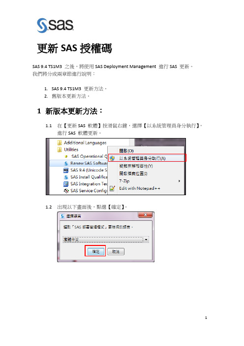
更新SAS授權碼
SAS 9.4 TS1M3 之後,將使用SAS Deployment Management 進行SAS 更新。
我們將分成兩章節進行說明:
1.SAS 9.4 TS1M3 更新方法。
2.舊版本更新方法。
1新版本更新方法:
1.1在【更新SAS 軟體】按滑鼠右鍵,選擇【以系統管理員身分執行】,
進行SAS 軟體更新。
1.2出現以下畫面後,點選【確定】。
1.3出現以下畫面,呼叫SAS Deployment Management 進行授權碼更新。
1.4出現以下畫面後,點選【下一步】。
1.5點選【瀏覽】,選擇更新SID路徑,在按【下一步】
1.6點選【開始】,進行SAS 授權碼更新。
您的SID檔案路徑
1.7出現以下畫面後,點選【下一步】。
1.8出現以下畫面,點選【完成】完成SAS授權碼更新。
2舊版本更新方法:
2.1在【更新SAS 軟體】按滑鼠右鍵,選擇【以系統管理員身分執行】,
進行SAS 軟體更新。
2.2點選【Browse】,選擇更新SID路徑,在按【Next】。
您的SID檔案路徑
2.3點選【Renew】。
2.4點選【確定】,完成更新授權。
- 1、下载文档前请自行甄别文档内容的完整性,平台不提供额外的编辑、内容补充、找答案等附加服务。
- 2、"仅部分预览"的文档,不可在线预览部分如存在完整性等问题,可反馈申请退款(可完整预览的文档不适用该条件!)。
- 3、如文档侵犯您的权益,请联系客服反馈,我们会尽快为您处理(人工客服工作时间:9:00-18:30)。
*PRODNUM538 = WKSPSRVLOCAL SAS Workspace Server for Local Access;
*PRODNUM550 = NETEZZABNDL SAS/ACCESS Netezza;
'PRODNUM560' 'PRODNUM677' 'PRODNUM678' '30APR2017'D
/ CPU=CPU000;
SAVE; RUN;
*DROPPED SAS/INSIGHT;
*DROPPED SAS/LAB;
*DROPPED SAS/Secure Windows;
*PRODNUM555 = ASTERBNDL SAS/ACCESS Interface to Aster nCluster;
*PRODNUM557 = GREENPLMBNDL SAS/ACCESS Interface to Greenplum;
*PRODNUM560 = SYBASEIQBNDL SAS/ACCESS Interface to Sybase IQ;
BIRTHDAY='24MAR2016'D EXPIRE='30APR2017'D PASSWORD=730951611;
CPU MODEL=' ' MODNUM=' ' SERIAL=' ' NAME=CPU000;
EXPIRE 'PRODNUM000' 'PRODNUM001' 'PRODNUM002' 'PRODNUM003'
*PRODNUM075 = INTTECHSRV SAS Integration Technologies;
*PRODNUM094 = SECUREBNDL SAS/Secure;
*PRODNUM095 = SECUREWBNDL SAS/Secure Windows;
*PRODNUM117 = GENETICSBNDL SAS/Genetics;
'PRODNUM075' 'PRODNUM094' 'PRODNUM095' 'PRODNUM117'
'PRODNUM119' 'PRODNUM123' 'PRODNUM164' 'PRODNUM165'
'PRODNUM166' 'PRODNUM167' 'PRODNUM192' 'PRODNUM194'
[_SID_]
Version=9.4
Revision=9.4
Platform_long=Microsoft Windows Workstation for x64
Platform_short=wx6
Order=9BHX96
License_prod=SAS
Setnumid=12001462
*PRODNUM194 = ORACLEBNDL SAS/ACCESS ORACLE;
*PRODNUM204 = SYBASE SAS/ACCESS SYBASE SQL;
*PRODNUM208 = PCFILE SAS/ACCESS PC Files;
*PRODNUM209 = ODBC SAS/ACCESS ODBC;
SID_schema=2
ph_agreement=PROMPT
SID_header=SAS 9.4
[_Info_]
[_FileData_]
$_Filename=setinit.sss
$_Path=sas\core\sasinst\
$_Date=
$_Time=
$_Stream=-------------------- BEGIN --------------------
*PRODNUM677 = HPS SAS High-Performance Server;
*PRODNUM678 = AMOEXCEL SAS Add-in for Microsoft Excel;
*LICENSE=SAS 000062109201;
*SITEID=661579;
*0023148003 9.4;
'PRODNUM204' 'PRODNUM208' 'PRODNUM209' 'PRODNUM215'
'PRODNUM219' 'PRODNUM225' 'PRODNUM448' 'PRODNUM535'
'PRODNUM538' 'PRODNUM550' 'PRODNUM555' 'PRODNUM557'
*PRODNUM000 = BASE Base SAS;
*PRODNUM001 = STAT SAS/STAT;
*PRODNUM002 = GRAPH SAS/GRAPH;
*PRODNUM003 = ETS SAS/ETS;
*PRODNUM004 = FSP SAS/FSP;
*PRODNUM005 = OR SAS/OR;
Microsoft Windows Workstation for x64
Base SAS 30APR2017
Education Analytical Suite 30APR2017
SAS Bridge for Esri 30APR2017
SAS Enterprise Guide 30APR2017
*PRODNUM006 = AF SAS/AF;
*PRODNUM007 = IML SAS/IML;
*PRODNUM008 = QC SAS/QC;
*PRODNUM010 = SHARE SAS/SHARE;
*PRODNUM013 = ASSIST SAS/ASSIST;
*PRODNUM015 = CONNECT SAS/CONNECT;
'PRODNUM004' 'PRODNUM005' 'PRODNUM006' 'PRODNUM007'
'PRODNUM008' 'PRODNUM010' 'PRODNUM013' 'PRODNUM015'
'PRODNUM025' 'PRODNUM035' 'PRODNUM050' 'PRODNUM070'
*PRODNUM166 = ORIVS SAS/OR Interactive Visualization and Simulation;
*PRODNUM167 = ORLSO SAS/OR Local Search Optimization;
*PRODNUM192 = DB2BNDL SAS/ACCESS DB2;
SAS Enterprise Miner for Desktop 30APR2017
SAS Integration Technologies 30APR2017
SAS/AF 30APR2017
SAS/ASSISTபைடு நூலகம்30APR2017
SAS/CONNECT 30APR2017
SAS/EIS 30APR2017
*PRODNUM119 = EGUIDE SAS Enterprise Guide;
*PRODNUM123 = ESRIBRDGORD SAS Bridge for ESRI;
*PRODNUM164 = OROPT SAS/OR Optimization;
*PRODNUM165 = ORPRS SAS/OR Project and Resource Scheduling;
*PRODNUM025 = EIS SAS/EIS;
*PRODNUM035 = SHARENET SAS/SHARE*NET;
*PRODNUM050 = DMINESOL Enterprise Miner Server;
*PRODNUM070 = MDDBCOM MDDB Server common products;
*XYZ 661579;
$_Stream=--------------------- END ---------------------
$_Filename=tletter.txt
$_Path=.\
$_Date=
$_Time=
$_Stream=-------------------- BEGIN --------------------
PROC SETINIT RELEASE='9.4';
SITEINFO NAME='NATIONAL PINGTUNG UNIV OF SCIENCE & TECHNOLOGY'
SITE=12001462 OSNAME='WX64_WKS' RECREATE WARN=30 GRACE=30
SAS/ETS 30APR2017
SAS/FSP 30APR2017
SAS/GRAPH 30APR2017
SAS/Genetics 30APR2017
