PELCO-D与PELCO-P协议介绍
pelco p协议
pelco p协议Pelco P协议是一种用于视频监控系统的通信协议,它定义了设备之间的通信规则和数据格式,使得不同厂家生产的设备可以互相通信和协作。
Pelco P协议广泛应用于监控摄像机、数字视频录像机(DVR)、网络视频录像机(NVR)等设备之间的通信。
首先,Pelco P协议采用了串行通信方式,使用RS-485接口进行数据传输。
这种通信方式可以实现多台设备之间的数据传输,而且可以覆盖较长的通信距离,这使得Pelco P协议在大型监控系统中得到了广泛的应用。
其次,Pelco P协议规定了设备之间的通信命令格式,包括起始位、地址位、命令位、数据位、校验位等。
这些规定确保了不同厂家生产的设备可以准确地解析和执行通信命令,从而实现了设备之间的互操作性。
另外,Pelco P协议还定义了一系列的通信命令,用于控制监控摄像机的运动、变焦、光圈等功能。
通过这些通信命令,用户可以远程控制监控摄像机,实现对监控区域的全方位监控。
除此之外,Pelco P协议还支持设备之间的数据传输,比如视频数据、报警数据等。
这些数据可以通过Pelco P协议进行可靠的传输,从而实现了监控系统的数据共享和协作。
总的来说,Pelco P协议作为一种通用的监控系统通信协议,为不同厂家生产的设备之间的互联互通提供了标准化的解决方案。
它的出现和应用,极大地促进了监控系统的发展和应用,为用户提供了更加便利和高效的监控解决方案。
在实际应用中,我们可以根据Pelco P协议的规范,开发符合标准的监控设备和系统,从而实现设备之间的互联互通。
同时,用户也可以根据Pelco P协议的规定,选购符合标准的监控设备,从而构建稳定、可靠、高效的监控系统。
总之,Pelco P协议作为一种重要的监控系统通信协议,对于监控系统的发展和应用起到了重要的推动作用。
它的出现和应用,为监控系统的互联互通提供了标准化的解决方案,为用户提供了更加便利和高效的监控体验。
相信随着技术的不断进步和发展,Pelco P协议将会在监控领域发挥出更加重要的作用。
PELCO D_P协议
PELCO D、P通讯协议一、PELCO协议介绍1、PELCO主控与前端解码器是通过RS422\RS485通信格式传输。
2、除PELCO原装设备支持RS422和RS485兼容接口,国内大部分厂家主控和接收设备仅支持RS485接口,RS485接口是半双工通信模式,即发送端发过去的控制命令,只管发出去,不管你收不收得到,有的厂家连续发,有的间隔发,总类很多。
停止命令往往发1、2条。
如PELCO\PANASONIC、三星等大厂做的通信接口,主控发出去命令,接收端收到命令返回SCK命令给主控,叫回答命令,告知发送端我已收到命令,不用再发了,这就是RS422通信模式的一种用途。
3、PELCO协议内容包括云台控制命令、摄像机控制命令、辅助控制命令、预置位设置和调用命令。
注意:网上PELCO协议版本众多,建议看家选择英文版本,中文版本很多错误。
4、Pelco P protocol details are proprietary, non-public documents. In almost all cases, Pelco's publicly available ASCII, G, or D protocols can be used in place of Pelco P with the appropriate translator. Pelco Product Support technicians may be able to assist you in obtaining the use of these protocols for your application. ASCII, G, and D protocols can be obtained be filling out our online registration form located here. For further assistance please contact Pelco Product Support at (800)298-9100 or (559)292-1981./sites/global/en/sales-and-support/support-services/obtaining-pelco-protocol.page二、PELCO-D协议数据格式:1位起始位、8位数据、1位停止位,无效验位。
PLOC-协议详解

PELCO-D协议内容介绍:D协议字节数:7个1字节:头字节永远是FF ;2字节:地址字节,01-256,从1开始;3、4字节:云台和摄像机控制字节,5、6字节:云台水平和垂直速度级字节;7字节:校验字节,是第2到第6字节的或OR。
速度级D协议是从00-63个级。
云台和摄像机字节控制位命令如下表:举例:关闭摄像机光圈命令,地址01,D协议命令是:FF 01 04 00 00 00 05;看上表,光圈关闭在第3字节的第2位,则为00000100二进制,16进制则是04H。
第4字节的控制命令如上。
关于云台自动功能如何实现,云台的自动功能是做到解码板电路,有多种硬件电路方法,也有软件检测限位开关或者光耦中断来控制左和右自动扫描。
但上面协议表是没有自动命令,在P协议里AUTO PAN命令是CALL 99号预置位。
在D协议里是没有定义,编程者可以定义CALL #NO来实现。
D协议特殊命令控制表:第3字节第4字节第5字节第6字节上表第6字节的数值范围编程者可以随便定义范围。
D协议,地址1,命令串如下:close: FF 01 04 00 00 00 05 停止:FF 01 00 00 00 00 01 open: FF 01 02 00 00 00 03 停止:FF 01 00 00 00 00 01 near: FF 01 01 00 00 00 02 停止:FF 01 00 00 00 00 01 far: FF 01 00 80 00 00 81 停止:FF 01 00 00 00 00 01 tele: FF 01 00 20 00 00 21 停止:FF 01 00 00 00 00 01 wide: FF 01 00 40 00 00 41 停止:FF 01 00 00 00 00 01 up: FF 01 00 08 00 20 29 停止:FF 01 00 00 00 00 01 down: FF 01 00 10 00 20 31 停止:FF 01 00 00 00 00 01 left: FF 01 00 04 20 00 25 停止:FF 01 00 00 00 00 01 right: FF 01 00 02 20 00 23 停止:FF 01 00 00 00 00 01preset #1: FF 01 00 03 00 01 05call #1 : FF 01 00 07 00 01 09menu : FF 01 00 03 00 5F 63tour: FF 01 00 07 00 4C 54 停止:FF 01 00 07 00 60 68scan: FF 01 00 07 00 63 6B 停止:FF 01 00 07 00 60 68pgm: FF 01 00 25 00 00 26 自定义的建议编程者在做控制串口软件时,没帧命令输出时间间隔最好定义200ms/ 帧。
云台通讯协议
竭诚为您提供优质文档/双击可除云台通讯协议篇一:几种云台控制协议pelco产品协议解析pelco(派尔高)的监控器材在我国有很广泛的应用。
pelco有自己的传输控制协议,当它的产品配套使用时,可以互相兼容。
但在某些情况下,由于工程的需要,要求用其它设备(比如电脑)来控制pelco的矩阵或镜头,这就要求充分了解pelco的传输协议。
诶诺基数码科技有限公司的视频解码软件可完全兼容pelco协议,可通过pc机控制pelco的各种设备。
本文为你详细解析pelco常用协议之一:pelco-d协议pelco-d协议pelco-d协议一般用于矩阵和其它设备之间的通信。
它的格式如下:所有的值都是用的16进制表示。
同步字通常都是$FF。
地址码是指与矩阵通信的那台设备的逻辑地址,可以在设备中设置。
命令字1和命令字2设置如下:sence码与bit4和bit3有关。
在bit4和bit3为1的情况下,如果sence码为1,则命令就是自动扫描和和摄像机打开;如果sence码为0,则命令就是手动扫描和摄像机关闭。
当然如果bit4或bit3为0的话那命令就无效了。
数据1表示镜头左右平移的速度,数值从$00(停止)到$3F(高速),另外还有一个值是$FF,表示最高速。
数据2表示镜头上下移动的速度,数值从$00(停止)到$3F(最高速)。
校验码是指byte2到byte6这5个数的和(若超过255则除以256然后取余数)。
pelco-d&pelco-p协议格式高速球的设置主要包括协议的选择和消息的发送。
高速球的型号是:tmd-scs18dn使用的协议有:bo1,alec,pelco -9600,pelco-4800,pelco-2400,ao1,santach1650,peaRmain,kony19.2kbkony20.832,hd600,lil in,kalatel,Vcl,tota,wj-Fs616,philips,ad.厂家设置的是pelco-2400.该协议的具体内容如下:pelco-d协议一般用于矩阵和其它设备之间的通信。
PELCO-D控制协议

控制协议1、通令参数:标准速率为4800bps,无校验,8位数据位,1位停止位2、命令串格式:一个PTZ控制命令为7字节的十六进制代码,格式如下:同步字节为$FF。
地址字节为受控制的PG解码器的十六进制地址,从1开始编号校验字节为Word2到Word 6的检验和(CheckSum)校验码= MOD[(字节2 + 字节3 + 字节4 + 字节5 + 字节6)/100H] Command 1 and Command 2 如下:注:云台自动由Command 1的Bit 7和Bit 4控制:为$90时云台自动开。
Data1(Word5)数据码1控制水平方向速度00-3FHData2(Word6)数据码2控制垂直方向速度00-3FH。
注:停止命令停止当前云台及镜头的动作,其Word3到Word6全为0。
辅助继电器开关命令也为7字节长度,其Word 1、Word2、Word 7同上,控制线连接方式:A 485+B 485-TX+ 485+TX- 485-解码器控制代码示例若非特意注明,控制1号解码器为例一、云台动作命令上:(按下)FF 01 00 08 00 2F 38 (弹起)FF 01 00 00 00 00 012号上:(按下)FF 02 00 08 00 2F 39 (弹起)FF 02 00 00 00 00 02下:(按下)FF 01 00 10 00 2F 40 (弹起)FF 01 00 00 00 00 01左:(按下)FF 01 00 04 2F 00 34 (弹起)FF 01 00 00 00 00 01右:(按下)FF 01 00 02 2F 00 32 (弹起)FF 01 00 00 00 00 01自动:(开)FF 01 90 00 00 00 91 (关)FF 01 00 00 00 00 01二、镜头控制命令光圈:开(按下)FF 01 02 00 00 00 03 (弹起)FF 01 00 00 00 00 01关(按下)FF 01 04 00 00 00 05 (弹起)FF 01 00 00 00 00 01变倍:小(按下)FF 01 00 20 00 00 21 (弹起)FF 01 00 00 00 00 01大(按下)FF 01 00 40 00 00 41 (弹起)FF 01 00 00 00 00 01聚焦:近(按下)FF 01 01 00 00 00 02 (弹起)FF 01 00 00 00 00 01远(按下)FF 01 00 80 00 00 81 (弹起)FF 01 00 00 00 00 01三、辅助继电器控制命令AU×1:(断开)FF 01 00 0B 00 01 0D (闭合)FF 01 00 09 00 01 0B AU×2:(断开)FF 01 00 0B 00 02 0E (闭合)FF 01 00 09 00 02 0C AU×3:(断开)FF 01 00 0B 00 03 0F (闭合)FF 01 00 09 00 03 0D AU×4:(断开)FF 01 00 0B 00 04 10 (闭合)FF 01 00 09 00 04 0E说明:1、云台上下左右及镜头控制按钮弹起时必须发出停止命令。
pelco-p协议和pelco-d协议地址

编号:_______________本资料为word版本,可以直接编辑和打印,感谢您的下载pelco-p协议和pelco-d协议地址甲方:___________________乙方:___________________日期:___________________pelco-p协议和pelco-d 协议地址篇一:pelco-d 与pelco-p 协议区另Upelco-d 与pelco-p 协议区另U曼码协议是ad品牌的协议,通用性很好,派尔高p、d 协议是派而高自己的协议,所以用矩阵控制快球,要考虑协议的问题,大部分矩阵厂家都提供协议转换器,而且大多数快球厂家也把解码器内内置多种协议,基本没有匹配问题,都是485的控制协议。
pelco-d:数据格式:1位起始位、8位数据、1位停止位,无效验位。
波特率:2400b/s命令格式:1. 该协议中所有数值都为十六进制数2. 同步字节始终为FFh3. 地址码为摄像机的逻辑地址号,地址范围:00h - FFh4. 指令码表示不同的动作5. 数据码1、2分别表示水平、垂直方向速度(00-3Fh ) ,FFh 表示“turbo ”速度6. 校验码=mod[(字节2+字节3+字节4+字节5+字节6)/100h]以地址码0x01为例:(0xff,0x01,0x00,0x08,0x00,0xff,0x08,}// 上(0xff,0x01,0x00,0x10,0x00,0xff,0x10,}// 下(0xff,0x01,0x00,0x04,0xff,0x00,0x04,}// 左(0xff,0x01,0x00,0x02,0xff,0x00,0x02,}// 右(0xff,0x01,0x00,0x20,0x00,0x00,0x21,}// 变倍短(0xff,0x01,0x00,0x40,0x00,0x00,0x41,}// 变倍长(0xff,0x01,0x00,0x80,0x00,0x00,0x81,}// 聚焦近(0xff,0x01,0x01,0x00,0x00,0x00,0x02,}// 聚焦远(0xff,0x01,0x02,0x00,0x00,0x00,0x03,}// 光圈小(0xff,0x01,0x04,0x00,0x00,0x00,0x05,}// 光圈大(0xff,0x01,0x00,0x0b,0x00,0x01,0x0d,}// 灯光关(0xff,0x01,0x00,0x09,0x00,0x01,0x0b,}// 灯光开(0xff,0x01,0x00,0x07,0x00,0x01,0x09,}// 转至预置点001(0xff,0x01,0x00,0x03,0x00,0x01,0x05,}// 设置预置点001(0xff,0x01,0x00,0x05,0x00,0x01,0x07,}// 删除预置点001以上对应的停命令均是:(0xff,0x01,0x00,0x00,0x00,0x00,0x01,}// 停命令pelco-p:数据格式:1位起始位、8位数据、1位停止位,无效验位。
pelco协议
pelco协议Pelco协议。
Pelco协议是一种用于视频监控系统的通讯协议,它定义了摄像机和控制设备之间的通讯方式,使得用户可以通过控制设备对摄像机进行控制和监控。
Pelco协议的应用范围非常广泛,几乎所有的视频监控设备都支持Pelco协议,因此了解Pelco协议的原理和应用对于视频监控系统的设计和维护具有重要意义。
首先,Pelco协议采用了串行通讯方式,通讯速率一般为2400、4800、9600、19200或者38400 bps。
这种通讯方式可以保证数据传输的稳定性和可靠性,适用于长距离的数据传输。
此外,Pelco协议采用了异步通讯方式,即数据的传输不需要时钟信号,这样可以减少通讯线路的复杂性,提高了系统的稳定性。
其次,Pelco协议定义了一套丰富的指令集,用于控制摄像机的各种功能。
这些指令包括云台的上下左右移动、变焦、聚焦、预置位设置等功能,用户可以通过控制设备发送这些指令来实现对摄像机的远程控制。
此外,Pelco协议还支持多种协议格式,包括Pelco-D、Pelco-P等,可以满足不同厂家、不同型号的设备之间的通讯需求。
另外,Pelco协议还具有较强的扩展性和灵活性。
用户可以根据自己的需求定制特定的控制指令,以满足特定的应用场景。
同时,Pelco协议还支持多种数据传输格式,包括ASCII码、二进制码等,这样可以适应不同的通讯环境和设备要求。
总的来说,Pelco协议作为视频监控系统中最重要的通讯协议之一,具有通讯速率快、稳定可靠、功能丰富、扩展性强等特点,为视频监控系统的设计和应用提供了重要的支持。
在实际应用中,用户需要根据自己的实际需求选择合适的通讯速率、协议格式和控制指令,以确保系统的稳定性和可靠性。
总之,了解Pelco协议的原理和应用对于视频监控系统的设计和维护具有重要意义。
希望本文的介绍能够帮助用户更加深入地了解Pelco协议,并能够在实际应用中发挥其最大的作用。
Pelco协议的不断发展和完善,必将为视频监控系统的发展带来更多的便利和可能。
PELCO-D与PELCO-P协议介绍
{0xff,0x01,0x00,0x07,0x00,0x01,0x09,}//转至预置点001
{0xff,0x01,0x00,0x03,0x00,0x01,0x05,}//设置预置点001
{0xff,0x01,0x00,0x05,0x00,0x01,0x07,}//删除预置点001
PELCO常用的两种协议:PELCO-D协议和PELCO-P协议。
- PELCO-D协议解析
PELCO-D协议一般用于矩阵和其它设备之间的通信。它的格式如下:
Byte 1 Byte 2 Byte 3 Byte 4 Byte 5 Byte 6 Byte 7
同步字 地址码 命令字1 命令字2 数据1 数据2 校验码
以上对应的停命令均是:
{0xff,0x01,0x00,0x00,0x00,0x00,0x01,}//停命令
PELCO-P:
数据格式:1位起始位、8位数据、1位停止位,无效验位。波特率:9600B/S
命令格式:
字节1 字节2 字节3 字节4 字节5 字节6 字节7 字节8
所有的值都是用的 16进制表示。
同步字通常都是 $FF。
地址码是指与矩阵通信的那台设备的逻辑地址,可以在设备中设置。
命令字 1和命令字2设置如下:
Bit 7 Bit 6 Bit 5 Bit 4 Bit 3 Bit 2 Bit 1 Bit 0
命令字1 Sence码 为0 为0 自动/手动扫描 摄像机打开/关闭 光圈关闭 光圈打开 焦距拉近
{0xa0,0x01,0x00,0x04,0x10,0x00,0xaf,0x15,}//左
{0xa0,0x01,0x00,0x02,0x10,0x00,0xaf,0x13,}//右
PELCO-D控制协议

控制协议1、通令参数:标准速率为4800bps,无校验, 8位数据位,1位停止位2、命令串格式:一个PTZ控制命令为7字节的十六进制代码,格式如下:同步字节为$FF。
地址字节为受控制的PG解码器的十六进制地址,从1开始编号校验字节为Word2到Word 6的检验和(CheckSum)校验码 = MOD[(字节2 + 字节3 + 字节4 + 字节5 + 字节6)/100H]注:云台自动由Command 1的Bit 7和Bit 4控制:为$90时云台自动开。
Data1(Word5)数据码1控制水平方向速度00-3FHData2(Word6)数据码2控制垂直方向速度00-3FH。
注:停止命令停止当前云台及镜头的动作,其Word3到Word6全为0。
辅助继电器开关命令也为7字节长度,其Word 1、Word2、Word 7同上,控制线连接方式:A 485+B 485-TX+ 485+TX- 485-解码器控制代码示例若非特意注明,控制1号解码器为例一、云台动作命令上:(按下)FF 01 00 08 00 2F 38 (弹起)FF 01 00 00 00 00 01 2号上:(按下)FF 02 00 08 00 2F 39 (弹起)FF 02 00 00 00 00 02 下:(按下)FF 01 00 10 00 2F 40 (弹起)FF 01 00 00 00 00 01 左:(按下)FF 01 00 04 2F 00 34 (弹起)FF 01 00 00 00 00 01 右:(按下)FF 01 00 02 2F 00 32 (弹起)FF 01 00 00 00 00 01 自动:(开)FF 01 90 00 00 00 91 (关) FF 01 00 00 00 00 01二、镜头控制命令光圈:开(按下)FF 01 02 00 00 00 03 (弹起)FF 01 00 00 00 00 01 关(按下)FF 01 04 00 00 00 05 (弹起)FF 01 00 00 00 00 01 变倍:小(按下)FF 01 00 20 00 00 21 (弹起)FF 01 00 00 00 00 01 大(按下)FF 01 00 40 00 00 41 (弹起)FF 01 00 00 00 00 01 聚焦:近(按下)FF 01 01 00 00 00 02 (弹起)FF 01 00 00 00 00 01 远(按下)FF 01 00 80 00 00 81 (弹起)FF 01 00 00 00 00 01三、辅助继电器控制命令AU×1:(断开)FF 01 00 0B 00 01 0D (闭合)FF 01 00 09 00 01 0B AU×2:(断开)FF 01 00 0B 00 02 0E (闭合)FF 01 00 09 00 02 0C AU×3:(断开)FF 01 00 0B 00 03 0F (闭合)FF 01 00 09 00 03 0D AU×4:(断开)FF 01 00 0B 00 04 10 (闭合)FF 01 00 09 00 04 0E说明:1、云台上下左右及镜头控制按钮弹起时必须发出停止命令。
PELCO D_P协议PDF.pdf
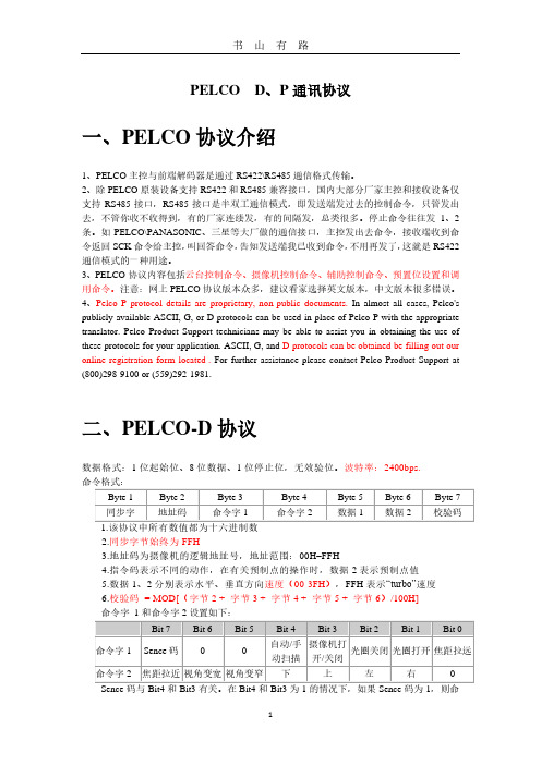
PELCO D、P通讯协议一、PELCO协议介绍1、PELCO主控与前端解码器是通过RS422\RS485通信格式传输。
2、除PELCO原装设备支持RS422和RS485兼容接口,国内大部分厂家主控和接收设备仅支持RS485接口,RS485接口是半双工通信模式,即发送端发过去的控制命令,只管发出去,不管你收不收得到,有的厂家连续发,有的间隔发,总类很多。
停止命令往往发1、2条。
如PELCO\PANASONIC、三星等大厂做的通信接口,主控发出去命令,接收端收到命令返回SCK命令给主控,叫回答命令,告知发送端我已收到命令,不用再发了,这就是RS422通信模式的一种用途。
3、PELCO协议内容包括云台控制命令、摄像机控制命令、辅助控制命令、预置位设置和调用命令。
注意:网上PELCO协议版本众多,建议看家选择英文版本,中文版本很多错误。
4、Pelco P protocol details are proprietary, non-public documents. In almost all cases, Pelco's publicly available ASCII, G, or D protocols can be used in place of Pelco P with the appropriate translator. Pelco Product Support technicians may be able to assist you in obtaining the use of these protocols for your application. ASCII, G, and D protocols can be obtained be filling out our online registration form located . For further assistance please contact Pelco Product Support at (800)298-9100 or (559)292-1981.二、PELCO-D协议数据格式:1位起始位、8位数据、1位停止位,无效验位。
PELCO协议中文版
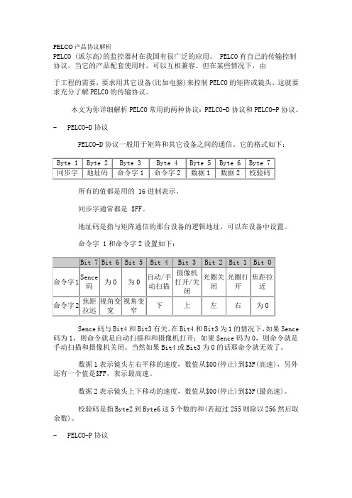
PELCO产品协议解析PELCO (派尔高)的监控器材在我国有很广泛的应用。
PELCO有自己的传输控制协议,当它的产品配套使用时,可以互相兼容。
但在某些情况下,由于工程的需要,要求用其它设备(比如电脑)来控制PELCO的矩阵或镜头,这就要求充分了解PELCO的传输协议。
本文为你详细解析PELCO常用的两种协议:PELCO-D协议和PELCO-P协议。
- PELCO-D协议PELCO-D协议一般用于矩阵和其它设备之间的通信。
它的格式如下:所有的值都是用的 16进制表示。
同步字通常都是 $FF。
地址码是指与矩阵通信的那台设备的逻辑地址,可以在设备中设置。
命令字 1和命令字2设置如下:Sence码与Bit4和Bit3有关。
在Bit4和Bit3为1的情况下,如果Sence 码为1,则命令就是自动扫描和和摄像机打开;如果Sence码为0,则命令就是手动扫描和摄像机关闭。
当然如果Bit4或Bit3为0的话那命令就无效了。
数据1表示镜头左右平移的速度,数值从$00(停止)到$3F(高速),另外还有一个值是$FF,表示最高速。
数据2表示镜头上下移动的速度,数值从$00(停止)到$3F(最高速)。
校验码是指Byte2到Byte6这5个数的和(若超过255则除以256然后取余数)。
- PELCO-P协议PELCO-P协议一般采用RS-485传输,波特率为4800,1位起始位和停止位,8位数据位,无校验。
其格式如下:起始码是固定值$A0。
地址码是设备的逻辑地址,可由接收设备上的DIP开关来设定。
数据位1到4的意义如下:停止码是固定值 $AF 。
校验码是 Byte2 到 Byte6 这 5 个数的异或值(XOR)。
地址码是从 0编起的,所以地址码$00表示第一台设备。
PELCO-D和PELCO-P协议另有一些特殊命令,可对设备进行一些高级控制,但这些应用并不常见,限于篇幅,这里不多作介绍,若需要可从直接下载英文资料。
详解PELCO-PD协议(软件编程篇)
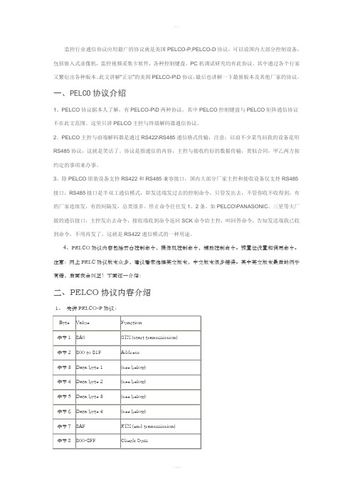
监控行业通信协议应用最广的协议就是美国PELCO-P,PELCO-D协议,可以说国内大部分控制设备,包括嵌入式录像机,监控视频采集卡软件,各种控制键盘,PC机调试研究均有此协议。
其中通过各个行家又繁衍出各种版本。
此文讲解“正宗”的美国PELCO-P\D协议,最后也讲解一下最新版本及其他厂家的协议。
一、PELCO协议介绍1、PELCO协议据本人了解,有PELCO-P\D两种协议。
其中PELCO控制键盘与PELCO矩阵通信协议不在此文范围。
这里只讲PELCO主控与终端解码器通信协议。
2、PELCO主控与前端解码器是通过RS422\RS485通信格式传输,注意:以前不少菜鸟问我的设备是用RS485协议,这就是笑话了。
协议是指通信的内容,主控与接收约好的数据传输,类似合同,甲乙两方按约定的事项来办事。
3、除PELCO原装设备支持RS422和RS485兼容接口,国内大部分厂家主控和接收设备仅支持RS485接口,RS485接口是半双工通信模式,即发送端发过去的控制命令,只管发出去,不管你收不收得到,有的厂家连续发,有的间隔发,总类很多。
停止命令往往发1、2条。
如PELCO\PANASONIC、三星等大厂做的通信接口,主控发出去命令,接收端收到命令返回SCK命令给主控,叫回答命令,告知发送端我已收到命令,不用再发了,这就是RS422通信模式的一种用途。
4、PELCO协议内容包括云台控制命令,摄像机控制命令,辅助控制命令。
预置位设置和调用命令。
注意:网上PELC协议版本众多,建议看家选择英文版本,中文版本很多错误。
其中英文版本最后的例子有错,后面我会纠正!下面逐一介绍:二、PELCO协议内容介绍1、先讲PELCO-P协议:看上表:P协议一共8个字节,头字节是A0,第2个字节是地址00-31(一共32个地址),32个地址现在大系统已经不够用了,所以我们要更改它,可以改成00-63个地址,00-127个地址。
地址在软件里随便增加的。
PELCO的D协议通讯协议
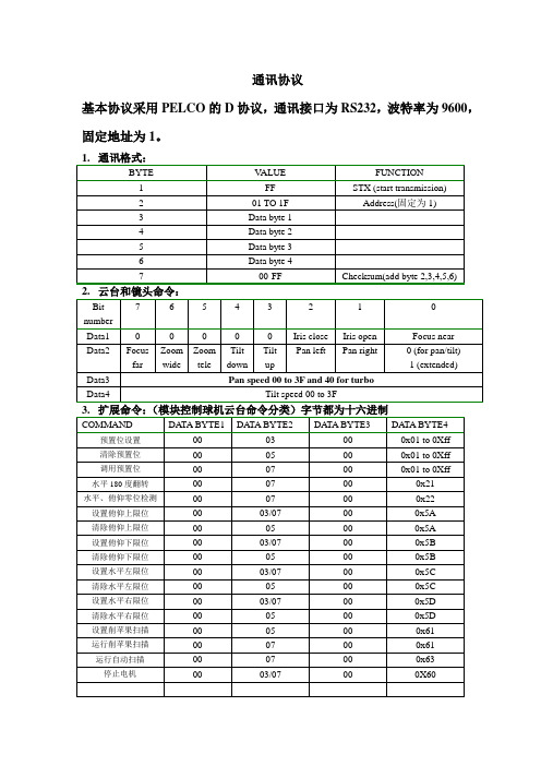
通讯协议
基本协议采用PELCO的D协议,通讯接口为RS232,波特率为9600,固定地址为1。
注:报警协议是云台主动发送报警信息给网络模块的。
1. 触发报警发送0X01.报警撤消发送0X00.
2. 当云台上电5分钟内,每分钟发一次当前的报警信息给网络模块。
之后当有报警信息变化才发送信息给网络模块。
3.数据反馈通讯
4.设置水平位置:水平位置(微步数)=PAN H(24B)<<16+PAN M(16B)<<8+PAN L(8B).
5.设置俯仰位置:俯仰位置(微步数)=TIL H(24B)<<16+TIL M(16B)<<8+TIL L(8B). 注:水平位置与俯仰位置均为微步数。
5. 发送变倍位置
注:如日立SC110相机。
模块发查询变倍指令给相机(:rF7140000)相机反馈命令(如:H’WXYZ )
模块就发命令(FF 01 00 37 WX YZ CHECKSUM)
当云台需要查询变倍时(FF 01 00 65 00 00 66)。
模块也要将变倍位置发下来。
Pelco-P Pelco-D与Sensormatic集成设备说明书
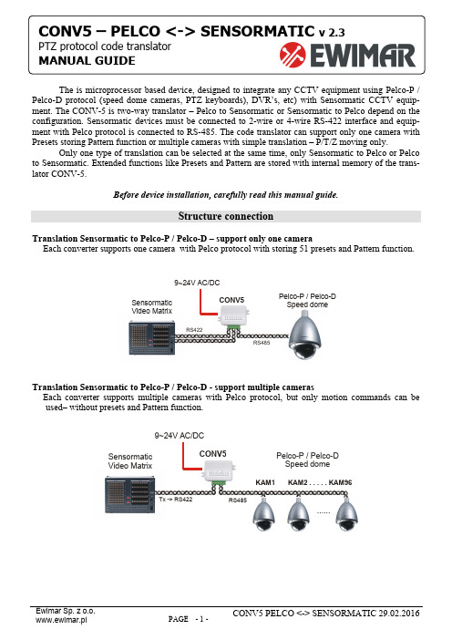
The is microprocessor based device, designed to integrate any CCTV equipment using Pelco-P / Pelco-D protocol (speed dome cameras, PTZ keyboards), DVR’s, etc) with Sensormatic CCTV equip-ment. The CONV-5 is two-way translator – Pelco to Sensormatic or Sensormatic to Pelco depend on the configuration. Sensormatic devices must be connected to 2-wire or 4-wire RS-422 interface and equip-ment with Pelco protocol is connected to RS-485. The code translator can support only one camera with Presets storing Pattern function or multiple cameras with simple translation – P/T/Z moving only.Only one type of translation can be selected at the same time, only Sensormatic to Pelco or Pelco to Sensormatic. Extended functions like Presets and Pattern are stored with internal memory of the trans-lator CONV-5.Before device installation, carefully read this manual guide.Structure connectionTranslation Sensormatic to Pelco-P / Pelco-D – support only one cameraEach converter supports one camera with Pelco protocol with storing 51 presets and Pattern function.Sensormatic Video MatrixRS485RS422Pelco-P / Pelco-D Speed domeCONV59~24V AC/DCTranslation Sensormatic to Pelco-P / Pelco-D - support multiple camerasEach converter supports multiple cameras with Pelco protocol, but only motion commands can be used– without presets and Pattern function.Sensormatic Video MatrixRS485Tx -> RS422Pelco-P / Pelco-D Speed domeCONV5-D9~24V AC/DC......KAM1KAM2 . . . . .KAM96CONV5 – PELCO <-> SENSORMATICTranslation Pelco to Sensormatic – support only one cameraEach converter supports one camera of Sensormatic, with 51 presets stored in the CONV or 96 presets if can be stored in camera (depend for camera type) and Pattern function. Some Sensormatic cameras support only 6 presets stored in camera memory, then up to 51 presets can be stored in converter mem-ory.Pelco-D/P keyboardRS485RS422SENSORMATIC Speed domeCONV59~24V AC/DCTranslation Pelco to Sensormatic – support multiple camerasEach converter supports multiple cameras with Sensormatic protocol, but only motion commands can be used– without Presets and Pattern function.Pelco-D/P keyboardRS485SENSORMATIC Speed dome CONV59~24V AC/DCKAM1KAM2 . . . . . .KAM96RS-422 -> RxSwitches and connection terminalCHANGE CONFIGURATIONDIP switches are used to configuration of the CONV5. To change most configurations, power supply must be disconnected from the unit. Other some changes will no have the effect.OFF (UP)ON(DOWN)CONNECTION TERMINALLED1 – Transmission indication of translationLED2 – Transmission indication of input dataLED lights are flashing due the time of transmission in proper protocols. The lack of flashing means connection error or converter switches setting.P o w e r P o w e r R S 485 - A +R S 485 - B -G N D S e n s o r m a t i c T e r m 1R S 422 R x +R S 422 R x -R S 422 T x -R S 422 T x +TRANSLATION SENSORMATIC TO PELCOCONNECTIONS FOR ONE CAMERA SUPPORT MODEP o w e r P o w e r R S 485 - A +R S 485 - B -G N D T e r m 1R S 422 R x +R S 422 R x -R S 422 T x -R S 422 T x +T o Pelco D / P Speed DomeTx+Tx-Rx+Rx-From RS422 port Video Matrix (Sensormatic)Above drawing explains how to connect one camera in mode. Then Preset and Pattern will be available. For this mode 4-wire connection of RS-422 bus is used. We suggest to place translator direct at Sensormatic Video Matrix. If more Pelco cameras is needed to connect in this mode, one translator per one camera must be used. Everything translators must be connected in the same port of Sensormatic Video MatrixPower Supply: 9~24V DC / ACSensormaticRS-422, used to connect converter to Sensormatic Video Matrix or Sensormatic Speed Some – depend on configurationPelco P /DRS-485, used to connect Pelco Speed Dome,(Pelco-D or Pelco-P protocol) with PTZ keyboard with Pelco.GND: These are terminals for connecting the shielding of theRS-485(cable shield).For long cables of RS-485 bus, should be connected to termi-nating resistor (120 Ohm). This will prevent wave reflections in cables, which are cause of transmission errors.Terminating resistors should be connected only on first and last devices. To many resistors can overload RS-485 driver.The CONV-5 translator have internal resistor only for RS-485port. To close terminating resistor please make wire link be-tween TERM and A+ terminals. For RS-422 must be used external resistors between + and – terminal – only when cables are longer than 50m.CONNECTIONS FOR MULTIPLE CAMERASP o w e r P o w e r R S 485 - A +R S 485 - B -G N D T e r m 1R S 422 R x +R S 422 R x -R S 422 T x -R S 422 T x +T o Pelco D / P Speed DomeTx+Tx-From RS422 port Video Matrix (Sensormatic)Above drawing explains how to connect many cameras to one converter. Because at this mode memory of converter can't uses, Presets or Pattern functions are not available.For connection in this mode only two wires of RS-422 port is needed. Converter will operate camera ad-dresses 1-96 (depend on matrix switcher configuration).GENERAL CONFIGURATION FOR TRANSLATION SENSORMATIC TO PELCODescription of switches:Transmission speed Pelco camera2400baud 4800baud 9600baud 19200baud DIP 1 OFF ON OFF ON DIP 2 OFF OFF ON ONSwitches defines transmission baud rate for Pelco-P / Pelco-D camera.Output protocol Pelco-D Pelco-PDIP 3 OFF ONSwitch defines type of output protocol for Pelco.Presets 1, 49, 59 used to Pattern supportNot active Active DIP 4 OFF ONWhen function is active:Call preset No1 - run programmed Pattern.Call preset No 49 - start programming Pattern with full range of speed movement Call preset No 50 - stop programming Pattern.Notice! Before use presets 1, 49, and 50 they must be stored in the video matrixConversion mode Pelco to Sensormatic Sensormatic to PelcoDIP 5 ONTo get translation from Sensormatic to Pelco, DIP No5 must be ON during change configuration.Delay between commands Short LongDIP 7 OFF ONSometimes when Pelco camera can't receive too many data, can work instable. In this situation DIP 6 should be ON to intro-duce 100ms delay between each commands. Normally should be OFF to fastest reaction.Saving configurationDIP 8 To save configuration, must be turned ONHOW TO SET GENERAL CONFIGURATION1. Disconnect power supply from the CONV52. Set the switches DIP 8 and DIP 5 to ON position.3. Set other switches as you need4.Connect power supply into the CONV5 continue on next page >>>5. Wait until red LED will start flashing, then disconnect a power supply.6. Set the switch DIP 8 to OFF position – (DIP 5 leave ON)7. Connect power supply into the CONV5.SELECT CONFIGURATION FOR ONE CAMERA OT MULTIPLE CAMERASSetting address determines support one camera or multiple cameras. When address is set as NONE trans-lator dues support multiple cameras. When any address is set, translator does support one camera with determined address. Address is binary set in according to the following table.1. Disconnect power supply from the CONV52. Set the switches 1~8 (DIP 8 must be OFF).3. Set address required address (for multiple cameras “NONE” – DIP1-7 OFF)4.Connect power supply into the CONV5If you want to change address again, please reply steps 1-4.Address1 2 3 4 5 6 7 8 Address 1234567847 ● ● ● ● ● 48 ● ● 49 ● ● ● NONEAll TURNED OFF – mean supportmultiple camera50 ● ● ● 1 ● 51 ● ● ● ● 2 ● 52 ● ● ● 3 ● ● 53 ● ● ● ● 4 ● 54 ● ● ● ● 5 ● ● 55 ● ● ● ● ● 6 ● ● 56 ● ● ● 7 ● ● ● 57 ● ● ● ● 8 ● 58 ● ● ● ● 9 ● ● 59 ● ● ● ● ● 10 ● ● 60 ● ● ● ● 11 ● ● ● 61 ● ● ● ● ● 12 ● ● 62 ● ● ● ● ● 13 ● ● ● 63 ● ● ● ● ● ● 14 ● ● ● 64 ● 15 ● ● ● ● 65 ● ● 16 ● 66 ● ● 17 ● ● 67 ● ● ● 18 ● ● 68 ● ● 19 ● ● ● 69 ● ● ● 20 ● ● 70 ● ● ● 21 ● ● ● 71 ● ● ● ● 22 ● ● ● 72 ● ● 23 ● ● ● ● 73 ● ● ● 24 ● ● 74 ● ● ● 25 ● ● ● 75 ● ● ● ● 26 ● ● ● 76 ● ● ● 27 ● ● ● ● 77 ● ● ● ● 28 ● ● ● 78 ● ● ● ● 29 ● ● ● ● 79 ● ● ● ● ● 30 ● ● ● ● 80 ● ● 31 ● ● ● ● ● 81 ● ● ● 32 ● 82 ● ● ● 33 ● ● 83 ● ● ● ● 34 ● ● 84 ● ● ● 35 ● ● ● 85 ● ● ● ● 36 ● ● 86 ● ● ● ● 37 ● ● ● 87 ● ● ● ● ● 38 ● ● ● 88 ● ● ● 39 ● ● ● ● 89 ● ● ● ● 40 ● ● 90 ● ● ● ● 41 ● ● ● 91 ● ● ● ● ● 42 ● ● ● 92 ● ● ● ● 43 ● ● ● ● 93 ● ● ● ● ● 44 ● ● ● 94 ● ● ● ● ● 45 ● ● ● ● 95 ● ● ● ● ● ● 46●●●●OFF96●●OFF● – Mean switch is TURNED ONFor one camera support mode number of camera controlled from matrix switcher, converter address and camera address with Pelco protocol must be the same, other way operating is not possible. Only exception are cameras with Pelco-P, which received address must be lower than that indicated on the settings made in it.START-UP FOR SENSORMATIC TO PELCO TRANSLATIONMake sure if polarization of RS-485 or RS-422 interfaces is correct.Correct operation of the translator can be determined by observing the LEDs. The green LED flashes when data from the matrix are interpreted correctly by the converter. The red LED indicates that the received data has been converted and transmitted to the camera with Pelco protocol.To make sure camera is properly detected, in system can not exist camera with the same ID address on Sensornet or Manchester bus.At 4 wire connection of RS-422 configuration converter is automatically detected as RS-422 Ultra Dome camera. At 2-wire mode type of camera must be set manually in the Video Matrix as below.SET VIDEO MATRIX IN MULTIPLE CAMERA SUPPORT MODE:To proper work in multiple mode, you should set model …SD ULTRA 3,4 or 5 (422)”manually in Sen-sormatic Video Matrix. To do that we should:Example for VM96 matrix switcher1. Enter menu: Config -> Cameras.2. Press ALT + S, select GoTo and confirm by pressing ENTER.3. Select from the list the type of camera that will be changed and press ENTER.4. Go to the "Camera Type" and delete the position by pressing the DEL.5. Move the arrow down one row below.6. Return the up arrow to the "Camera Type" - a list of cameras to choose from is displayed. Youmust select from a list of camera "SD ULTRA 3.4 or 5 (422)" and confirm with Enter.7. Exit the menu and reselect by Touch Tracker keyboard the camera you want to control.To change the settings for other cameras, repeat steps 2 ~ 6.The second way to set up the camera is connect the converter as in for one camera (4-wire connection) mode and set the camera address to be controlled by the converter. These types of camera will be automatically detected and set in the matrix.1. Connect the RS-422 bus as for CONV5-A mode - 4 wires.2. Disconnect the power supply of converter.3. Set by switches on converter the number of the camera to be controlled by it - identically as forCONV-A mode.4. Select on the Touch Tracker keyboard the camera number that has been set.5. Connect the power supply to converter.6. Wait until the on monitor appears Camera XX is ONLINE (XX is the number of the camera)7. Disconnect the power supply of converter.8. Set on the converter switches for CONV5-D mode.9. Connect the power supply to converter.To change the settings for other cameras, repeat steps 2 ~ 6. 4-wire connection can stay, it will not affect the operation of the system.OPERATING AT TRANSLATION SENSORMATIC TO PELCO MODEMotion controlMotion control is fully accessible via the TouchTracker keyboard in accordance with their instructions. At the same time can be used to control the direction of the camera and the lens (aperture, focus and and zoom).Pattern function support (only camera support mode)By the CONV5 can be saved one Pattern in Pelco camera – by way described in manual of Touch tracker and Video Matrix. While programming the Pattern rotation speed is reduced twice, which is imposed by the Video Matrix of Sensormatic. The converter support only the first Pattern on the list created for each camera in the Video Matrix, another Patterns are ignored.Preset function support (only camera support mode)In CONV5 we can programed 50 presets (View) + preset 95, which in cameras with Pelco protocol is used to Entry Menu.Starting Preset (View) works in accordance with to the instructions for TouchTracker keyboard.To program a preset, follow the steps below. DO NOT disconnect a power supply during below operations1. Remember current settings of the switches on the converter.2. Use the TouchTracker keyboard to set the camera in the desired position.3. Select the preset number (DIP 1-7) on the converter and turn on the switch No. 8.4. Save the preset using the TouchTracker keyboard.5. Set the switches to the previous position and turn off the switch no.To program the other presets, repeat steps 2 ~ 4.Preset 1 2 3 4 5 6 7 8 Preset 1 2 3 4 5 6 7 8●31 ●●●●●●NoneInactive 32 ●●1 ●●33 ●●●2 ●●34 ●●●3 ●●●35 ●●●●4 ●●36 ●●●5 ●●●37 ●●●●6 ●●●38 ●●●●7 ●●●●39 ●●●●●8 ●●40 ●●●9 ●●●41 ●●●●10 ●●●42 ●●●●11 ●●●●43 ●●●●●12 ●●●44 ●●●●13 ●●●●45 ●●●●●14 ●●●●46 ●●●●●15 ●●●●●47 ●●●●●●16 ●●48 ●●●17 ●●●49 ●●●●18 ●●●50 ●●●●19 ●●●●95 ●●●●●20 ●●●21 ●●●●22 ●●●●23 ●●●●●24 ●●●25 ●●●●26 ●●●●27 ●●●●●Preset No 95 usually is used to entry to menu of Pelcocamera.Before use this preset must be stored in Video matrix28 ●●●●29 ●●●●●30 ●●●●●● – Switch TURNED ONTRANSLATION PELCO TO SENSORMATICCONNECTIONS FOR ONE CAMERA SUPPORT MODEP o w e r P o w e r R S 485 - A +R S 485 - B -G N D T e r m 1R S 422 R x +R S 422 R x -R S 422 T x -R S 422 T x +From Pelco PTZ keyboardTx+Tx-Rx+Rx-T o RS-422 port in Sensormatic Speed DomeAbove drawing explains how to connect one camera in mode, which supports Preset and Pattern function. For this mode 4-wire connection of RS-422 bus is used. We suggest to place translator direct at Sensormatic Speed Dome. If more Sensrmatic cameras is needed to connect in this mode, one translator per one camera must be used.CONNECTIONS FOR MULTIPLE CAMERASP o w e r -P o w e r R S 485 - A +R S 485 - B -G N D T e r m 1R S 422 R x +R S 422 R x -R S 422 T x -R S 422 T x+From Pelco PTZ keyboardRx+Rx-T o RS-422 port in Sensormatic Speed DomeAbove drawing explains how to connect many cameras with a single converter. Because in this mode memory of converter can not be used, Presets or Pattern functions are not available.For connection in this mode, only two wires of RS-422 port is needed. Converter will operate camera addresses 1-254 .GENERAL CONFIGURATION FOR TRANSLATION PELCO TO SENSORMATIC1. Disconnect power supply from the CONV52. Set the switches DIP 8 and DIP 5 to OFF position.3. Set other switches as you need4.Connect power supply into the CONV55. Wait until red LED will start flashing, then disconnect a power supply.6. Set the switch DIP 8 to OFF position – (DIP 5 leave OFF)7. Connect power supply into the CONV5Description of switches:2400baud 4800baud 9600baud 19200baud Transmission speedFor Pelco cameraDIP 1 OFF ON OFF ONDIP 2 OFF OFF ON ONSwitches define transmission speed for Pelco-P / Pelco-D keyboard.Input protocol Pelco-D Pelco-PDIP 3 OFF ONConversion mode Pelco to Sensormatic Sensormatic to PelcoDIP 5 OFFTo get translation from Pelco to Sensormatic, DIP No5 must be OFF during change configuration.Storing of Presets Preset will be stored in Camera Preset will be stored in ConverterDIP 6 OFF ON Up to 96 presets can be stored in the Camera (if camera support preset storing). Up to 51 presets can be stored in the con-verter. Set Preset 95 always is used to entry camera menu, call preset 95 always is used to exit camera menu (if camera sup-ports it).Delay between commands Short LongDIP 7 OFF ON Sometimes when Pelco keyboard send too many data, Sensormatic camera can have problems with STOP. In this situationDIP 6 should be ON to introduce 100ms pause between each commands. Normally should be OFF.Saving configurationDIP 8 To save configuration, must be turned ONWARNING! If the CONV5 worked at Sensormatic to Pelco mode before, everything stored presets can be deleted.SELECT CONFIGURATION FOR ONE CAMERA OT MULTIPLE CAMERASSetting address determines support one camera or multiple cameras. When address is set as NONE trans-lator does support multiple cameras. When any address is set, translator does support one camera withdetermined address. Address is binary set in according to the following table on PAGE 5.START-UP FOR PELCO TO SENSORMATIC TRANSLATIONMake sure if polarization of RS-485 or RS-422 interfaces is correct.Correct operation of the translator can be determined by observing the LEDs.The green LED indicates that the received data has been converted and transmitted to the camera withPelco protocol. The red LED flashes when data from the keyboard are translated and send to camera.OPERATING IN TRANSLATION SENSORMATIC TO PELCO MODEMotion controlUsing for each keyboard, in accordance with its user guide. At the same time can be controlled Pan, Tilt, and Zoom.Support Pattern functionBy the CONV5 can be saved one Pattern in Sensormatic camera – by way described in manual of Pelco PTZ keyboard. While programming the Pattern speed of rotation is reduced to 2 speeds – this is typicall for Sensormatic cameras. The converter support only one Pattern. The pattern working in loop mode after start.Support Preset functionIn CONV5 we can stored 51 presets (saved in converter memory) or up to 96 presets (saved in camera memory). It depend for camera model.。
PELCO协议

PELCO协议协议名称: PELCO协议一、背景介绍PELCO协议是一种用于视频监控和安防系统的通信协议,由美国PELCO公司开发。
该协议旨在实现视频设备之间的互联互通,包括摄像机、录像机、监视器等设备。
PELCO协议已经成为行业内广泛采用的标准,为视频监控系统的正常运行和管理提供了基础。
二、协议目的本协议的目的是规范PELCO协议的使用和实施,确保视频监控和安防系统的各个设备能够正确地进行通信和协作。
本协议旨在提供一个统一的标准,使不同厂家的设备能够无缝集成,实现互操作性。
三、协议内容1. 协议版本PELCO协议的当前版本为V1.0。
本协议的使用应遵循该版本的规范。
2. 协议结构PELCO协议采用二进制数据格式进行通信。
每个数据包由固定的数据结构组成,包括起始字节、命令码、数据长度、数据内容、校验和等字段。
3. 数据通信PELCO协议使用串行通信方式进行数据传输。
通信速率应根据设备的技术规格进行设置,以确保数据的准确传输。
4. 命令码PELCO协议定义了一系列命令码,用于控制和管理视频设备。
常见的命令码包括:- 云台控制命令:用于控制云台设备的运动,包括上下左右移动、变焦、变倍等功能。
- 镜头控制命令:用于控制摄像机的镜头参数,包括焦距、光圈等。
- 预置位命令:用于设置和调用摄像机的预置位,以实现快速定位和巡航功能。
- 录像控制命令:用于控制录像机的录像和回放功能。
5. 数据解析接收方应根据PELCO协议的规范对接收到的数据进行解析和处理。
解析过程应包括校验和验证、命令码解析、数据内容解析等步骤,以确保数据的准确性和完整性。
6. 错误处理在数据通信过程中,如果发生错误或异常情况,接收方应及时进行错误处理。
错误处理包括错误码的返回、错误信息的显示等,以便操作人员能够及时采取相应的措施。
7. 安全性PELCO协议的使用应遵循相关的安全规范和要求,确保视频监控和安防系统的安全性。
包括但不限于对通信数据的加密、身份验证、访问控制等措施。
PELCO_D协议说明
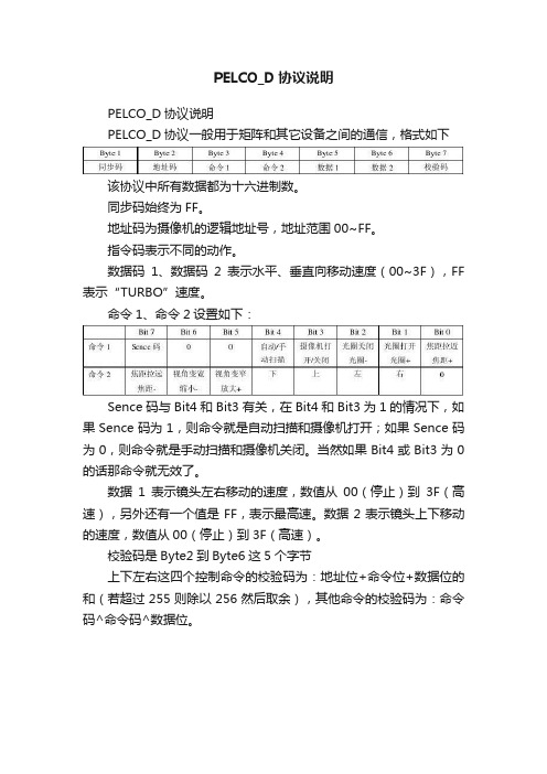
PELCO_D协议说明
PELCO_D协议说明
PELCO_D协议一般用于矩阵和其它设备之间的通信,格式如下
该协议中所有数据都为十六进制数。
同步码始终为FF。
地址码为摄像机的逻辑地址号,地址范围00~FF。
指令码表示不同的动作。
数据码1、数据码2表示水平、垂直向移动速度(00~3F),FF 表示“TURBO”速度。
命令1、命令2设置如下:
Sence码与Bit4和Bit3有关,在Bit4和Bit3为1的情况下,如果Sence码为1,则命令就是自动扫描和摄像机打开;如果Sence码为0,则命令就是手动扫描和摄像机关闭。
当然如果Bit4或Bit3为0的话那命令就无效了。
数据1表示镜头左右移动的速度,数值从00(停止)到3F(高速),另外还有一个值是FF,表示最高速。
数据2表示镜头上下移动的速度,数值从00(停止)到3F(高速)。
校验码是Byte2到Byte6这5个字节
上下左右这四个控制命令的校验码为:地址位+命令位+数据位的和(若超过255则除以256然后取余),其他命令的校验码为:命令码^命令码^数据位。
- 1、下载文档前请自行甄别文档内容的完整性,平台不提供额外的编辑、内容补充、找答案等附加服务。
- 2、"仅部分预览"的文档,不可在线预览部分如存在完整性等问题,可反馈申请退款(可完整预览的文档不适用该条件!)。
- 3、如文档侵犯您的权益,请联系客服反馈,我们会尽快为您处理(人工客服工作时间:9:00-18:30)。
PELCO-D:
数据格式:1位起始位、8位数据、1位停止位,无效验位。
波特率:2400B/S 命令格式:
1.该协议中所有数值都为十六进制数
2.同步字节始终为FFH
3.地址码为摄像机的逻辑地址号,地址范围:00H–FFH
4.指令码表示不同的动作
5.数据码1、2分别表示水平、垂直方向速度(00-3FH),FFH表示“turbo”速度
6.校验码= MOD[(字节2 + 字节3 + 字节4 + 字节5 + 字节6)/100H]
以地址码0x01为例:
{0xff,0x01,0x00,0x08,0x00,0xff,0x08,}//上
{0xff,0x01,0x00,0x10,0x00,0xff,0x10,}//下
{0xff,0x01,0x00,0x04,0xff,0x00,0x04,}//左
{0xff,0x01,0x00,0x02,0xff,0x00,0x02,}//右
{0xff,0x01,0x00,0x20,0x00,0x00,0x21,}//变倍短
{0xff,0x01,0x00,0x40,0x00,0x00,0x41,}//变倍长
{0xff,0x01,0x00,0x80,0x00,0x00,0x81,}//聚焦近
{0xff,0x01,0x01,0x00,0x00,0x00,0x02,}//聚焦远
{0xff,0x01,0x02,0x00,0x00,0x00,0x03,}//光圈小
{0xff,0x01,0x04,0x00,0x00,0x00,0x05,}//光圈大
{0xff,0x01,0x00,0x0b,0x00,0x01,0x0d,}//灯光关
{0xff,0x01,0x00,0x09,0x00,0x01,0x0b,}//灯光开
{0xff,0x01,0x00,0x07,0x00,0x01,0x09,}//转至预置点001
{0xff,0x01,0x00,0x03,0x00,0x01,0x05,}//设置预置点001
{0xff,0x01,0x00,0x05,0x00,0x01,0x07,}//删除预置点001
以上对应的停命令均是:
{0xff,0x01,0x00,0x00,0x00,0x00,0x01,}//停命令
PELCO-P:
数据格式:1位起始位、8位数据、1位停止位,无效验位。
波特率:9600B/S 命令格式:
1.该协议中所有数值都为十六进制数
2.STX始终为A0H
3.地址码为摄像机的逻辑地址号,地址范围:00H–1FH
4.指令码表示不同的动作
5.数据码1、2分别表示水平、垂直方向速度(00-3FH),在有关预制点的操作时,数据码2表示预制点值
6.ETX始终为AFH
7.校验码(XOR sum of Bytes 2-6) = 字节2 ^ 字节3 ^ 字节4 ^ 字节5 ^ 字节6
以地址码0x01为例:
{0xa0,0x01,0x00,0x08,0x00,0x30,0xaf,0x39,}//上
{0xa0,0x01,0x00,0x10,0x00,0x30,0xaf,0x21,}//下
{0xa0,0x01,0x00,0x04,0x10,0x00,0xaf,0x15,}//左
{0xa0,0x01,0x00,0x02,0x10,0x00,0xaf,0x13,}//右
{0xa0,0x01,0x00,0x40,0x00,0x00,0xaf,0x41,}//变倍短
{0xa0,0x01,0x00,0x20,0x00,0x00,0xaf,0x21,}//变倍长
{0xa0,0x01,0x02,0x00,0x00,0x00,0xaf,0x03,}//聚焦近
{0xa0,0x01,0x01,0x00,0x00,0x00,0xaf,0x00,}//聚焦远
{0xa0,0x01,0x08,0x00,0x00,0x00,0xaf,0x09,}//光圈小
{0xa0,0x01,0x04,0x00,0x00,0x00,0xaf,0x05,}//光圈大
无命令字发送//灯光关
无命令字发送//灯光开
{0xa0,0x01,0x00,0x96,0x00,0x20,0xaf,0xb7,}//自动巡航
{0xa0,0x01,0x00,0x99,0x00,0x20,0xaf,0xb8,}//关闭自动巡航
{0xa0,0x01,0x00,0x07,0x00,0x01,0xaf,0x07,}//转至预置点001
{0xa0,0x01,0x00,0x03,0x00,0x01,0xaf,0x03,}//设置预置点001
{0xa0,0x01,0x00,0x05,0x00,0x01,0xaf,0x01,}//删除预置点001
以上对应的停命令均是(上下左右、变倍、聚焦、光圈均有停命令): {0xa0,0x01,0x00,0x00,0x00,0x00,0xaf,0x01,}。
