Design and Application of Biofilter to Control Odor in Wastewater Treatment Plant
生物分离工程的英语

生物分离工程的英语Biological Separation Engineering is a specialized field that focuses on the isolation and purification of biological products. It plays a crucial role in the pharmaceutical, food, and biotechnology industries, where the extraction ofbioactive compounds from natural sources is essential.The process typically begins with the selection of an appropriate feedstock, which could be anything from plant material to microorganisms. Once the feedstock is identified, it undergoes a series of steps to separate the desired components. These steps may include:1. Pre-treatment: This involves breaking down the complex structure of the feedstock to release the target molecules. Techniques such as mechanical disruption, enzymatic digestion, or chemical treatment may be used.2. Extraction: The target molecules are then extractedfrom the pre-treated material. This can be done using solvent extraction, where a solvent is used to dissolve the desired compounds, or by using methods like supercritical fluid extraction, which employs high-pressure gases to extract the compounds.3. Concentration: After extraction, the solution is often diluted and needs to be concentrated to increase the concentration of the target molecules. This can be achievedthrough evaporation, membrane filtration, or centrifugation.4. Purification: The concentrated solution may still contain impurities, so further purification is necessary. Chromatography is a common technique used at this stage, which separates molecules based on their affinity to the stationary phase.5. Polishing: The final step is to polish the purified product to ensure it meets the required specifications. This may involve additional rounds of purification or the use of specific techniques to remove any remaining impurities.Biological separation engineering is a complex process that requires a deep understanding of both the properties of the target molecules and the various separation techniques available. Advances in this field are continually improving the efficiency and selectivity of these processes, making it possible to produce high-quality biological products for a wide range of applications.。
USP88生物实验

88 BIOLOGICAL REACTIVITY TESTS, IN VIVOThe following tests are designed to determine the biological response of animals to elastomerics, plastics, and other polymeric material with direct or indirect patient contact, or by the injection of specific extracts prepared from the material under test. It is essential to make available the specific surface area for extraction. When the surface area of the specimen cannot be determined, use 0.1 g of elastomer or 0.2 g of plastic or other material for every mL of extraction fluid. Also, it is essential to exercise care in the preparation of the materials to be injected or instilled to prevent contamination with microorganisms and other foreign matter. Three tests are described. The Systemic Injection Test and the Intracutaneous Test are used for elastomeric materials, especially to elastomeric closures for which the appropriate Biological Reactivity Tests, In Vitro 87 have indicated significant biological reactivity. These two tests are used for plastics and other polymers, in addition to a third test, the Implantation Test, to test the suitability of these materials intended for use in fabricating containers and accessories thereto, for use in parenteral preparations, and for use in medical devices, implants, and other systems.These three tests are applied to materials or medical devices, if there is a need for classification of plastics and other polymers based on in vivo biological reactivity testing.For the purpose of this chapter, these definitions apply: the Sample is the specimen under test or an extract prepared from such a specimen. A Blank consists of the same quantity of the same extracting medium that is used for the extraction of the specimen under test, treated in the same manner as the extracting medium containing the specimen under test. A Negative Control1is a specimen that gives no reaction under the conditions of the test.CLASSIFICATION OF PLASTICSSix Plastic Classes are defined (see Table 1). This classification is based on responses to a series of in vivo tests for which extracts, materials, and routes of administration are specified. These tests are directly related to the intended end-use of the plastic articles. The choice of extractants is representative of the vehicles in preparations with which the plastics are likely to be in contact. The Table 1 classification facilitates communication among suppliers, users, and manufacturers of plastics by summarizing the tests to be performed for containers for injections and medical devices if a need for classification exists.Table 1. Classification of PlasticsPlastic Classes a Tests to be ConductedI II III IV V VI Test Material Animal Dose Procedure bx x x x x x Extract ofSample inSodiumChlorideInjection Mouse 50 mL/kg A (IV)x x x x x x RabbitorGuineaPig0.2 mL/animalat each of 10 or 6sites B (IC)x x x x x Extract ofSample in 1 in20 Solution ofAlcohol inSodiumChlorideInjection Mouse 50 mL/kg A (IP)x x x x x RabbitorGuineaPig0.2 mL/animalat each of 10 or 6sites B (IC)x x xExtract ofSample inPolyethyleneGlycol 400Mouse 10 g/kg A (IP)x x RabbitorGuineaPig0.2 mL/animalat each of 10 or 6sites B (IC)x x x xExtract ofSample inVegetable Oil Mouse 50 mL/kg A (IP)x x x RabbitorGuineaPig0.2 mL/animalat each of 10 or 6sites B (IC)Plastic Classes a Tests to be ConductedI II III IV V VI Test Material Animal Dose Procedure bx x Implant stripsof Sample Rabbit 4 strips/animal Cx x Implant Sample Rat 2 Samples/animal Ca Tests required for each class are indicated by “x” in appropriate columns.b Legend: A (IP)—Systemic Injection Test (intraperitoneal); B (IC)—Intracutaneous Test (intracutaneous); C—Implantation Test (intramuscular or subcutaneous implantation).With the exception of the Implantation Test, the procedures are based on the use of extracts that, depending on the heat resistance of the material, are prepared at one of three standard temperatures: 50, 70, and 121. Therefore, the class designation of a plastic must be accompanied by an indication of the temperature of extraction (e.g., IV-121, which represents a class IV plastic extracted at 121, or I-50, which represents a class I plastic extracted at 50).Plastics may be classified as USP Plastic Classes I–VI only on the basis of the response criteria prescribed in Table 1.This classification does not apply to plastics that are intended for use as containers for oral or topical products, or that may be used as an integral part of a drug formulation. Table 1 does not apply to natural elastomers, which are to be tested in Sodium Chloride Injection and vegetable oils only.The Systemic Injection Test and the Intracutaneous Test are designed to determine the systemic and local, respectively, biological responses of animals to plastics and other polymers by the single-dose injection of specific extracts prepared from a Sample. The Implantation Test is designed to evaluate the reaction of living tissue to the plastic and other polymers by the implantation of the Sample itself into animal tissue. Theproper preparation and placement of the specimens under aseptic conditions are important in the conduct of the Implantation Test. These tests are designed for application to plastics and other polymers in the condition in which they are used. If the material is to be exposed to any cleansing or sterilization process prior to its end-use, then the tests are to be conducted on a Sample prepared from a specimen preconditioned by the same processing.Factors such as material composition, processing and cleaning procedures, contacting media, inks, adhesives, absorption, adsorption and permeability of preservatives, and conditions of storage may also affect the suitability of a material for a specific use. Evaluation of such factors should be made by appropriate additional specific tests to determine the suitability of a material for its intended use.USP R EFERENCE S TANDARDS 11—USP High-Density Polyethylene RS.Extracting Media—SODIUM CHLORIDE INJECTION (see monograph). Use Sodium Chloride Injection containing 0.9% of NaCl.1 IN 20 SOLUTION OF ALCOHOL IN SODIUM CHLORIDE INJECTION.POLYETHYLENE GLYCOL 400 (see monograph).VEGETABLE OIL— Use freshly refined Sesame Oil (see monograph) or Cottonseed Oil (see monograph) or other suitable vegetable oils.DRUG PRODUCT VEHICLE (where applicable).WATER FOR INJECTION (see monograph).NOTE—The Sesame Oil or Cottonseed Oil or other suitable vegetable oil meets the following additional requirements. Obtain, if possible, freshly refined oil. Use three properly prepared animals, and inject the oil intracutaneously in a dose of 0.2 mL into each of 10 sites per animal, and observe the animals at 24, 48, and 72 h following injection. Rate the observations at each site on the numerical scale indicated inTable 2. For the 3 rabbits or guinea pigs (30 or 18 injection sites), at any observation time, the average response for erythema is not greater than 0.5 and for edema is not greater than 1.0, and no site shows a tissue reaction larger than 10 mm in overall diameter. The residue of oil at the injection site should not be misinterpreted as edema. Edematous tissue blanches when gentle pressure is applied.Table 2. Evaluation of Skin Reactions aErythema and Eschar Formation ScoreNo erythema 0 Very slight erythema (barely perceptible) 1 Well-defined erythema 2 Moderate to severe erythema 3 Severe erythema (beet-redness) to slight eschar formation(injuries in depth) 4 Edema Formation b ScoreNo edema 0 Very slight edema (barely perceptible) 1 Slight edema (edges of area well defined by definite raising) 2 Moderate edema (raised approximately1 mm) 3 Severe edema (raised more than 1 mm and extending beyond the areaofexposure) 4a Draize JH, Woodward G, Calvery HO. Methods for the study of irritation and toxicity of substances applied topically to the skin and mucous membranes. J Pharmacol Exp Ther 1944;82:377–390.b Excludes noninflammatory (mechanical) edema from the blank or extraction fluid.Apparatus— The apparatus for the tests includes the following. AUTOCLAVE— Use an autoclave capable of maintaining a temperature of 121 ± 2.0, equipped with a thermometer, a pressure gauge, a vent cock, a rack adequate to accommodate the test containers above the water level, and a water cooling system that will allow for cooling of the test containers to about, but not below, 20 immediately following the heating cycle.OVEN— Use an oven, preferably a forced-circulation model, that will maintain operating temperatures of 50 or 70 within ±2. EXTRACTION CONTAINERS— Use only containers, such as ampuls or screw-cap culture test tubes, of Type I glass. If used, culture test tubes are closed with screw caps having suitable elastomeric liners. The exposed surface of the elastomeric liner is completely protected with an inert solid disk 0.05–0.075 mm in thickness. A suitable disk may be fabricated from a polytef resin.Preparation of Apparatus— Cleanse all glassware thoroughly with chromic acid cleansing mixture, or if necessary, with hot nitric acid, followed by prolonged rinsing with water. Clean cutting utensils by an appropriate method (e.g., successive cleaning with acetone and methylene chloride) prior to use in subdividing a specimen. Clean all other equipment by thorough scrubbing with a suitable detergent and prolonged rinsing with water.Render containers and equipment used for extraction, and in transfer and administration of test material, sterile and dry by a suitable process. [NOTE—If ethylene oxide is used as the sterilizing agent, allow adequate time for complete degassing. ]Procedure—PREPARATION OF SAMPLE— Both the Systemic Injection Test and the Intracutaneous Test may be performed using the same extract, if desired, or separate extracts may be made for each test. Select and subdivide into portions a Sample of the size indicated in Table 3. Remove particulate matter, such as lint and free particles, by treating each subdivided Sample or Negative Control as follows. Place the Sample into a clean, glass-stoppered, 100-mL graduated cylinder of Type I glass, and add about 70 mL of Water for Injection. Agitate for about 30 s, and drain off thewater. Repeat this step, and dry those pieces prepared for the extraction with Vegetable Oil in an oven at a temperature not exceeding 50. [NOTE —Do not clean the Sample with a dry or wet cloth or by rinsing or washing with an organic solvent, surfactant, etc. ]Table 3. Surface Area of Specimen To Be Used aForm ofMaterial Thickness Amount of Sample for each20 mL of Extracting Medium Subdivided intoFilm or sheet <0.5 mm Equivalent of 120 cm2totalsurface area (both sidescombined)Strips of about5 × 0.3 cm0.5–1 mm Equivalent of 60 cm2 total surface area (both sides combined)Tubing <0.5 mm(wall)Length (in cm) = 120cm2/(sum of ID and ODcircumferences)Sections ofabout5 × 0.3 cm0.5–1 mm(wall)Length (in cm) = 60 cm2/(sumof ID and ODcircumferences)Slabs, tubing,and moldeditems >1 mm Equivalent of 60 cm2 totalsurface area (all exposedsurfaces combined)Pieces up toabout 5 × 0.3cmElastomers >1 mm Equivalent of 25 cm2 totalsurface area (all exposedsurfaces combined) Do not subdivide ba When surface area cannot be determined due to the configuration of the specimen, use 0.1 g of elastomer or 0.2 g of plastic or other polymers for every 1 mL of extracting fluid.b Molded elastomeric closures are tested intact.PREPARATION OF EXTRACTS— Place a properly prepared Sample to be tested in an extraction container, and add 20 mL of the appropriate extracting medium. Repeat these directions for each extracting medium required for testing. Also, prepare one 20-mL blank of each medium for parallel injections and comparisons. Extract by heating in an autoclave at 121 for 60 min, in an oven at 70 for 24 h, or at 50 for 72 h. Allow adequatetime for the liquid within the container to reach the extraction temperature. [NOTE—The extraction conditions should not in any instance cause physical changes such as fusion or melting of the Sample pieces, which result in a decrease in the available surface area. A slight adherence of the pieces can be tolerated. Always add the cleaned pieces individually to the extracting medium. If culture tubes are used for autoclave extractions with Vegetable Oil, seal screw caps adequately with pressure-sensitive tape. ]Cool to about room temperature but not below 20, shake vigorously for several minutes, and decant each extract immediately, using aseptic precautions, into a dry, sterile vessel. Store the extracts at a temperature of 20–30, and do not use for tests after 24 h. Of importance are the contact of the extracting medium with the available surface area of the plastic and the time and temperature during extraction, the proper cooling, agitation, and decanting process, and the aseptic handling and storage of the extracts following extraction.SYSTEMIC INJECTION TESTThis test is designed to evaluate systemic responses to the extracts of materials under test following injection into mice. Alternate routes of injection may be used with justification.Test Animals— Use healthy, not previously used albino mice weighing 17–23 g. For each test group use only mice of the same source. Allow water and food, commonly used for laboratory animals and of known composition, ad libitum.Procedure—[NOTE—Agitate each extract vigorously prior to withdrawal of injection doses to ensure even distribution of the extracted matter. ] Inject each of the five mice in a test group with the Sample or the Blank as outlined in Table 4, except to dilute each g of the extract of the Sample prepared with Polyethylene Glycol 400, and the corresponding Blank, with 4.1 volumes of Sodium Chloride Injectionto obtain a solution having a concentration of about 200 mg of polyethylene glycol per mL.Table 4. Injection Procedure—Systemic Injection TestExtract or Blank Dose per kg Route a Sodium ChlorideInjection 50 mL IV1 in 20 solution ofAlcohol in Sodium Chloride Injection 50 mL IV Polyethylene Glycol 400 10 g IP Drug product vehicle (where applicable) 50 mL IV50 mL IP Vegetable Oil 50 mL IPa IV = intravenous (aqueous sample and blank); IP = intraperitoneal (oleaginous sample and blank).Observe the animals immediately after injection, again 4 h after injection, and then at least at 24, 48, and 72 h. If during the observation period none of the animals treated with the extract of the Sample shows a significantly greater biological reactivity than the animals treated with the Blank, the Sample meets the requirements of this test. If two or more mice die, or if abnormal behavior such as convulsions or prostration occurs in two or more mice, or if a body weight loss greater than 2 g occurs in three or more mice, the Sample does not meet the requirements of the test. If any animals treated with the Sample show only slight signs of biological reactivity, and not more than one animal shows gross symptoms of biological reactivity or dies, repeat the test using groups of 10 mice. On the repeat test, all 10 animals treated with the Sample show no significant biological reactivity above the Blank animals during the observation period.INTRACUTANEOUS TESTThis test is designed to evaluate local responses to the extracts of materials under test following intracutaneous injection into rabbits or guinea pigs.Test Animals— Select healthy, rabbits or guinea pigs with fur that can be clipped closely and skin that is free from mechanical irritation or trauma. In handling the animals, avoid touching the injection sites during observation periods, except to discriminate between edema and an oil residue.Procedure—[NOTE—Agitate each extract vigorously prior to withdrawal of injection doses to ensure even distribution of the extracted matter. ] On the day of the test, closely clip the fur on the animal's back on both sides of the spinal column over a sufficiently large test area. Avoid mechanical irritation and trauma. Remove loose hair by means of vacuum. If necessary, swab the skin lightly with diluted alcohol, and dry the skin prior to injection. More than one extract from a given material can be used per rabbit or guinea pig, if it is determined that the test results will not be affected. For each Sample use two animals and inject each intracutaneously, using one side of the animal for the Sample and the other side for the Blank, as outlined in Table 5. [NOTE—Dilute each g of the extract of the Sample prepared with Polyethylene Glycol 400, and the corresponding Blank, with 7.4 volumes of Sodium Chloride Injection to obtain a solution having a concentration of about 120 mg of polyethylene glycol per mL. ]Table 5. Intracutaneous TestExtract or Blank Number of Sites(per animal)Dose(µL per site)Sample 5 200Blank 5 200Examine injection sites for evidence of any tissue reaction such as erythema, edema, and necrosis. Swab the skin lightly, if necessary, with diluted alcohol to facilitate reading of injection sites. Observe all animals at 24, 48, and 72 h after injection. Rate the observations on anumerical scale for the extract of the Sample and for the Blank, using Table 2. Reclip the fur as necessary during the observation period. The average erythema and edema scores for Sample and Blank sites are determined at every scoring interval (24, 48, and 72 h) for each rabbit or guinea pig. After the 72-hour scoring, all erythema scores plus edema scores are totalled separately for each Sample and Blank. Divide each of the totals by 12 (2 animals × 3 scoring periods × 2 scoring categories) to determine the overall mean score for each Sample versus each corresponding Blank. The requirements of the test are met if the difference between the Sample and the Blank mean score is 1.0 or less. If at any observation period the average reaction to the Sample is questionably greater than the average reaction to the Blank, repeat the test using three additional rabbits or guinea pigs. The requirements of the test are met if the difference between the Sample and the Blank mean score is 1.0 or less.IMPLANTATION TESTThe implantation test is designed for the evaluation of plastic materials and other polymeric materials in direct contact with living tissue. Of importance are the proper preparation of the implant strips and their proper implantation under aseptic conditions. The intramuscular implantation test requires healthy adult New Zealand rabbits. The test specimens are placed into needles as the delivery system for implantation. Although most materials lend themselves readily to this method, there are a number of materials that are unsuitable for intramuscular implantation. For materials with physical characteristics unsuitable for routine intramuscular implantation, the subcutaneous rat implantation model is a viable alternative.Intramuscular Implantation in RabbitsPrepare for implantation 8 strips of the Sample and 4 strips of USP High-Density Polyethylene RS. Each strip should measure not less than 10 × 1 mm. The edges of the strips should be as smooth as possible to avoid additional mechanical trauma upon implantation. Strips of the specified minimum size are implanted by means of a hypodermic needle (15–19 gauge) with intravenous point and a sterile trocar. Use either presterilized needles into which the sterile plastic strips are aseptically inserted, or insert each clean strip into a needle, the cannula and hub of which are protected with an appropriate cover, and then subjected to the appropriate sterilization procedure. [NOTE—Allow for proper degassing if agents such as ethylene oxide are used. ]Test Animals— Select healthy, adult rabbits weighing not less than 2.5 kg, and with paravertebral muscles that are sufficiently large in size to allow for implantation of the test strips. Do not use any muscular tissue other than the paravertebral site. The animals must be anesthetized with a commonly used anesthetic agent to a degree deep enough to prevent muscular movements, such as twitching. See the Association for Assessment and Accreditation of Laboratory Animal Care (AAALAC) guidelines. Procedure— Perform the test in a clean area. On the day of the test or up to 20 h before testing, clip the fur of the animals on both sides of the spinal column. Remove loose hair by means of vacuum. Swab the skin lightly with diluted alcohol, and dry the skin prior to injection. Implant four strips of the Sample into the paravertebral muscle on one side of the spine of each of two rabbits, 2.5–5 cm from the midline and parallel to the spinal column, and about 2.5 cm apart from each other. In a similar fashion implant two strips of USP High-Density Polyethylene RS in the opposite muscle of each animal. Insert a sterile stylet into the needle to hold the implant strip in the tissue while withdrawing the needle. Ifexcessive bleeding is observed after implantation of a strip, place a duplicate strip at another site.Keep the animals for a period of not less than 120 h, and sacrifice them at the end of the observation period by administering an overdose of an anesthetic agent or other suitable agents. Allow sufficient time to elapse for the tissue to be cut without bleeding. Examine macroscopically the area of the tissue surrounding the center portion of each implant strip. Use a magnifying lens and auxiliary light source. Observe the Sample and Control implant sites for hemorrhage, necrosis, discolorations, and infections, and record the observations. Measure encapsulation, if present, by recording the width of the capsule (from the periphery of the space occupied by the implant Control or Sample to the periphery of the capsule) rounded to the nearest 0.1 mm. Score encapsulation according to Table 6.Table 6. Evaluation of Encapsulation in the Implantation TestCapsule Width ScoreNone 0Up to 0.5 mm 10.6–1.0 mm 21.1–2.0 mm 3Greater than 2.0 mm 4Calculate the differences between average scores for the Sample and Control sites. The requirements of the test are met if the difference does not exceed 1.0, or if the difference between the Sample and Control mean scores for more than one of the four implant sites does not exceed 1 for any implanted animal.Subcutaneous Implantation in RatsPrepare for implantation 10 sample specimens and 10 control specimens. The size and shape of the control specimens shall be as similar to that of the test specimens as practically possible. For example, specimens made of sheeting material shall be 10–12 mm in diameter and from 0.3–1 mmin thickness. The edges of the specimens should be as smooth as possible to avoid additional mechanical trauma upon implantation.Test Animals— Select healthy albino rats weighing 225–350 g at the time of implantation.Procedure— Perform the test in a clean area. Anesthetize (see AAALAC guidelines) the animal until a surgical plane is achieved. Clip the fur of the animals on both sides of the spinal column. Remove loose hair by means of vacuum. Clean the clipped area with povidone–iodine solution. Using aseptic technique, make two midline incisions (approximately 1.0 cm long) through the skin at the cranial and caudal regions on the dorsal surface. Using blunt dissection, separate the fascia connecting skin to muscle to form a pocket underneath the skin lateral to each side of the incision (base of pocket approximately 20 mm from the line of implant). Insert a sterile sample into each pocket, and close the incision with wound clips or sutures. Implant two test samples and two control samples in each of five rats. Keep the animals for a period of at least seven days, and sacrifice them at the end of the observation period by CO2induced hypoxia or administering an overdose of an anesthetic agent. Allow sufficient time to elapse for the tissue to be cut without bleeding. Cut the skin (dorsal surface) longitudinally and lay back. Carefully examine macroscopically the area of the tissue surrounding the implant. Cut the sample in half and remove for close examination of the tissue in direct contact with the sample. Use a magnifying lens and auxiliary light source, if appropriate. Observe the Sample and Control implant sites for hemorrhage, necrosis, discolorations, and infections, and record the observations. Measure encapsulation, if present, by recording the width of the capsule (from the periphery of the space occupied by the implant Control or Sample to the periphery of the capsule) rounded to the nearest 0.1 mm. Score encapsulation according to Table 6. Calculate the differences betweenaverage scores for the Sample and Control sites. The requirements of the test are met if the difference does not exceed 1.0.SAFETY TESTS—BIOLOGICALSThe safety test set forth here is intended to detect in an article any unexpected, unacceptable biological reactivity. This in vivo test is provided for the safety assessment of biotechnology-derived products.Safety TestSelect five healthy mice not previously used for testing, weighing 17–23 g, unless otherwise directed in the individual monograph or elsewhere in this chapter, and maintained on an adequate balanced diet. Prepare a test solution as directed in the individual monograph. Unless otherwise directed in the individual monograph or elsewhere in this chapter, inject a dose of 0.5 mL of the test solution into each of the mice, using a 26-gauge needle of suitable length, or of the length specified below as applicable. Observe the animals over the 48 h following the injection. If, at the end of 48 h, all of the animals survive and not more than one of the animals shows outward symptoms of a reaction not normally expected of the level of toxicity related to the article, the requirements of this test are met. If one or more animals die or if more than one of the animals shows signs of abnormal or untoward toxicity of the article under test, repeat the test using at least another 10 mice similar to those used in the initial test, but weighing 20 ± 1 g. In either case, if all of the animals survive for 48 h and show no symptoms of a reaction indicative of an abnormal or undue level of toxicity of the article, the requirements of the test are met. Body weights of mice before and at the end of the test should be obtained to detect any untoward effects. Animals that show signs of toxicity should be grossly necropsied and subjected to histopathology if necessary.For biologics, perform the test according to the procedures prescribed in the Code of Federal Regulations, Section 610.11.1 USP High-Density Polyethylene RS.Auxiliary Information—Please check for your question in the FAQs before contacting USP.Topic/Question Contact Expert CommitteeGeneral Chapter Desmond G. Hunt,Ph.D.Senior ScientificLiaison(301) 816-8341 (GCPS2010) General Chapters - Packaging Storage and DistributionReference Standards RS TechnicalServices1-301-816-8129rstech@USP38–NF33 Page 158Pharmacopeial Forum: Volume No. 38(2)。
英文-微膨胀的处理效果
Limited filamentous bulking in order to enhance integrated nutrient removal and effluent qualityWen-De Tian a ,b ,Wei-Guang Li a ,b ,*,Hui Zhang a ,b ,Xiao-Rong Kang a ,b ,Mark C.M.van Loosdrecht c ,daSchool of Municipal and Environmental Engineering,Harbin Institute of Technology,Harbin 150090,ChinabState Key Laboratory of Urban Water Resource Environment,Harbin Institute of Technology,Harbin 150090,China cDepartment of Biotechnology,Delft University of Technology,Julianalaan 67,2628BC Delft,The Netherlands dKWR Watercycle Research Institute,Groningenhaven 7,3422PE Nieuwegein,The Netherlandsa r t i c l e i n f oArticle history:Received 23December 2010Received in revised form 23June 2011Accepted 25June 2011Available online 6July 2011Keywords:Limited filamentous bulking Dissolved oxygen Settleability (SVI)Simultaneous nitrification and denitrification EBPRa b s t r a c tLimited filamentous bulking has been proposed as a means to enhance floc size and make conditions more favorable for simultaneous nitrification/Denitrification (SND).Moreover a slightly heightened SVI is supposed to increase the removal of small particulates in the clarifier.Integrated nitrogen,phosphorus and COD removal performance under limited filamentous bulking was investigated using a bench-scale plug-flow enhanced biological phosphorus removal (EBPR)reactor fed with raw domestic wastewater.Limited filamen-tous bulking in this study was mainly induced by low DO levels,while other influencing factors associated with filamentous bulking (F/M,nutrients,and wastewater characteris-tics)were not selective for filamentous bacteria.The optimum scenario for integrated nitrogen,phosphorus and COD removal was achieved under limited filamentous bulking with an SVI level of 170e 200(associated with a DO of 1.0e 1.5mg/L).The removal effi-ciencies of COD,TP and NH 4þe N were 90%,97%and 92%,respectively.Under these conditions,the solid e liquid separation was practically not affected and sludge loss was never observed.A well-clarified effluent with marginal suspended solids was obtained.The results of this study indicated the feasibility of limited filamentous bulking under low DO as a stimulation of simultaneous nitrification/denitrification for enhancing nutrient removal and effluent quality in an EBPR process.ª2011Elsevier Ltd.All rights reserved.1.IntroductionEnhanced biological phosphorus removal (EBPR)in activatedsludge systems characterized by high removal efficiency,economy,environmentally-friendly operation,and potential phosphorus recovery (Barat and van Loosdrecht,2006;Martı´et al.,2010),has become a popular and widespread tech-nology in wastewater treatment plants (WWTPs).However,filamentous sludge bulking has been reported for the EBPR process (Vaiopoulou et al.,2007)leading to sludge loss and poor solid e liquid separation,and therefore result in subse-quent upsets and deterioration in removal performance.Abundant previous researches were mainly focused on the study of the prevention,control and modeling of filamentous bulking in various activated sludge systems (Cenens et al.,2000;Martins et al.,2004b;Gulez and de los Reyes,2009).*Corresponding author .School of Municipal and Environmental Engineering,Harbin Institute of Technology,Harbin 150090,China.Tel./fax:þ8645186283003.E-mail addresses:tianwende@ (W.-D.Tian),hittwd@ (W.-G.Li),M.C.M.vanLoosdrecht@tudelft.nl (M.C.M.vanLoosdrecht).A v a i l a b l e a t w w w.s c i e n c e d i r e c t.c o mj o u r n a l h o m e p a g e :w w w.e l s e v i e r.c o m /l o c a t e /w a t r e sw a t e r r e s e a r c h 45(2011)4877e 48840043-1354/$e see front matter ª2011Elsevier Ltd.All rights reserved.doi:10.1016/j.watres.2011.06.034Specific (Martins et al.,2003a,b;Wanner et al.,2010)and non-specific (Liao et al.,2004;Martins et al.,2004a )methods as well as various biological selectors (Van Loosdrecht et al.,1998;Vaiopoulou and Aivasidis,2008)were developed to prevent and control filamentous bulking.Still the costs and the need for chemicals and operational control are the intractable issues,and the general cost effective and easy control solution has not been adopted by the plant operators.Recently,Peng et al.(2008)advocated an energy-saving method of limited filamentous bulking under low DO condition for the first time using anoxic-oxic (A/O)process and domestic wastewater.Thereafter Guo et al.(2010)developed the energy-saving theory and method of limited filamentous bulking,which minimizes energy consumption by taking advantage of higher oxygen transfer rate obtained under low DO level.However,hitherto the utilization of limited filamentous bulking induced by controlling low DO levels for the EBPR process and its influence on overall process performance were marginally documented.The lower DO concentration not only maintains a favorable anoxic environment but also can be favorable for simultaneous nitrification and denitrification (SND).Many researchers have been attracted by the simultaneous nitrification and denitrification (SND)technique because of its simplified process design and smaller anoxic zone,as well as no requirements of external carbon source and alkalinity while minimizing the need for sludge recycles (Ajay et al.,2006;Fu et al.,2009).The biological and physical explana-tions for SND are the coexistence of denitrifiers and autotro-phic nitrifiers and oxygen gradients within activated sludge flocs caused by the limitation of oxygen diffusion (Guo et al.,2005;Chiu et al.,2007).The oxygen gradients in biological floc lead to an interior anoxic microenvironment,which facilitates SND.The larger floc diameter has advantages to limit relative penetration depth of oxygen in the floc and therefore generate oxygen gradients and microbial process stratification,which has been described in the literatures (Chuet al.,2004;Li and Bishop,2004;Pe´rez et al.,2005).Andreadakis (1993)showed that microenvironments within the floc for SND was better formed with the floc size of 50e 100m m than 10e 70m m.Pochana and Keller (1999)found that the nitrogen removal efficiency via SND was increased by 31%when the average floc size increased from 40m m to 80m m.Some researches assumed that a bit larger floc diameter was likely to promote the SND due to diffusional limitation of oxygen inthe floc (Zhu et al.,2007;Guo et al.,2009).Dissolved oxygen is important for development of filamentous microorganism (Martins et al.,2003b,2004a ).Having a limited growth of fila-mentous bacteria will also achieve a better effluent quality due to the irregular filamentous morphology which givesa better filtering out of suspended particles (Wile´n and Balme ´r,1999;Guo et al.,2009,2010).The main objective of the present study is therefore to demonstrate limited filamentous bulking under low DO as a stimulation of SND to enhance biological nutrient removal and effluent quality.Experiments were carried out in a bench-scale EBPR process,designed according to a BCFS Òprocess (Van Loosdrecht et al.,1998).The removal performance of nitrogen,phosphorus and chemical oxygen demand (COD)were investigated at different SVI values in aerobic compartment.2.Materials and methods2.1.Reactor configuration and experimental setupLong-term experiments were performed in a bench-scale EBPR process,designed according to a BCFS Òprocess,as shown in Fig.1.The reactor was made of plexiglas with a total working volume of 27L,which was separated in four func-tional compartments by removable plastic sheets.The working volume of anaerobic,anaerobic selector,anoxic,anoxic/oxic and aerobic compartment is 5.4L,1.2L,5.4L,9L and 6L,respectively.A mechanical mixer was used in non-aerated zones to provide well mixed conditions.Aeration was supplied at the bottom of the aerobic compartments by an air compressor.A clarifier with a working volume of 9L was used for solid e liquid separation.The surface loading of the clarifier was 0.36m 3/m 2h.The flow rates of influent,return sludge,and the two internal recycle flows were controlled by four peristaltic pumps (Lange Z1515-100M,China).2.2.Wastewater compositionThe bench-scale EBPR reactor was fed with raw domestic sewage.There were no extra chemicals added.The composi-tions are described as follows.COD cr :183.5e 367mg/L;NH 4þeN:w a t e r r e s e a r c h 45(2011)4877e 4884487846.3e 62.5mg/L;TN:48.6e 71.5mg/L;TP 5.3e 10.9mg/L;SS:151e 200mg/L;pH:7.0e 7.7.The standard deviations of COD cr ,NH 4þe N,TN and TP of 90samples are 18.7,4.2,4.5and 0.8,respectively.2.3.Experimental operational conditions and proceduresThe reactor was inoculated with activated sludge collected from Wenchang municipal wastewater treatment plant (A/O process)of Harbin,PR China,the initial concentration of sludge in the reactor was set at 4g/L,and the reactor was fed with diluted raw domestic sewage for seven days to obtain constant colonization and accumulation of microorganism.Afterwards,the reactor was operated in a continuous plug-flow mode fed with raw domestic sewage.The reactor grad-ually stabilized after the acclimatization of 35days at the room temperature 22Æ3 C,DO of 1.5mg/L,hydraulic retention time (HRT)of anaerobic compartment (1.8h),anaerobic selector (0.4h),anoxic compartment (1.8h),anoxic/oxic compartment (3h),aerobic compartment (2h)and solid retention time (SRT)of 15days.During the steady-state periods,the recycling rate of sludge,nitrified liquor and denitrified liquor was set at 1.0,2.0and 1.5time of total influent flow rate,respectively.Then various investigations were conducted with different DO levels in the aerobic compartment.2.4.Analytical methodsAmmonia nitrogen (NH 4þe N),nitrate nitrogen(NO 3Àe N),nitrite nitrogen (NO 2Àe N),total phosphorus (TP)chemical oxygen demand (COD),mixed liquor suspended solids (MLSS),mixed liquor volatile suspended solids (MLVSS),alkalinity and sludge volume index (SVI)were measured according to the standard methods for the examination of water and wastewater (APHA,1998).The total nitrogen (TN)concentration was determined with LiquiTOCII (Elementar,Germany).The DO was measured by SG6-ELK SevenGo Pro (Mettler Toledo,Switzerland).The ORP,pH and temperature were measured with HI-8424pH meter (HANNA,Italy).Periodically microscopic observations of sludge samples from the aerobic compartment were per-formed with an Olympus IX51inverted microscope (Tokyo,Japan)and the microscopic analysis was according to the reference manuals (Eikelboom,2000;Jenkins et al.,2003).3.Results3.1.Occurrence and control of limited filamentous bulkingExtensive experiments have been performing for the optimi-zation of process parameters such as volume ratios of inter-active functional compartments,various recycling rate,SRT and DO in the past thirteen months.The occurrence of limited filamentous bulking was observed when the volume ratio of anaerobic,anoxic,anoxic/oxic and aerobic compartment was 1:1:1.7:1.1.Herein,DO concentration of the anoxic/oxic zone was constant in the range of 0.3e 1.0mg/L.Limited filamen-tous bulking is defined as sludge with an SVI of 140e 250.The proliferation of filamentous micro-organisms was found by periodic microscopic observations.However,the removal performance of TN and TP adversely enhanced,and COD removal was stable during the period of limited filamentous bulking,in parallel with a case of good sludge settleability.Particularly the poor solid e liquid separation and the loss of sludge were never observed.The phenomenon was consistent with the findings of a previous study (Guo et al.,2010).For the further research,limited filamentous bulking induced by DO level was studied.The relationship between settleability (SVI)and DO level under the prerequisite of suitable nutrients (N,P),food/micro-organisms ratio (F/M),wastewater characteristics,pH and temperature,is presented in Fig.2.There is an expected relationship between DO and SVI.Experimental results showed that it is easy to control the limited filamen-tous bulking by adjusting aerobic DO levels in this bench-scale plug-flow EBPR reactor.Subsequently,the effect of limited filamentous bulking on the pollutants removal performance was focused at different aerobic DO levels (1.0e 1.5,1.5e 2.0and 2.0e 3.0),which will be discussed further below.3.2.Overall performance of nutrient removal under limited filamentous bulking 3.2.1.COD removalThe organic loading rate of the reactor was in the range of 0.20e 0.39kgCOD kgMLSS À1d À1,which in general is supposed not to lead to filamentous bulking (Chudoba et al.,1974;Wanner et al.,2010).Fig.2(a)presented the COD removal efficiency under limited filamentous bulking in thebench-Fig.1e Schematic diagram of bench-scale EBPR reactor.(1)Influent tank;(2)feed pump;(3)mechanical mixer;(4)check valve;(5)diffuser;(6)airflow meter;(7)air compressor;(8)return nitrified liquor pump;(9)return denitrified liquor pump;(10)secondary clarifier;(11)effluent;(12)waste sludge;and (13)return sludge pump.w a t e r r e s e a r c h 45(2011)4877e 48844879Fig.2e The removal efficiencies of COD,NH 4D e N,TP at different SVI periods (a:COD removal;b:NH 4De N removal;c:TP removal).The nutrient removal efficiencies were compared under the condition of normal settleability and limited filamentous bulking.w a t e r r e s e a r c h 45(2011)4877e 48844880scale EBPR reactor.The observed trends of COD removal effi-ciencies and effluent COD are very similar even though the SVI increased from 100to 200,which means the COD removal performance is not affected by limited filamentous bulking.Previous researches have showed that COD removal efficiency was slightly interfered under filamentous bulking caused by overpopulation of Haliscomenobacter hydrossis (Kotay et al.,2010).The influent COD concentration had an average value of 260mg/L ranging from 184to 367mg/L,whereas effluent concentrations had an average value of 30mg/L fluctuating between 17and 40mg/L.Total COD removal efficiency with had an average value of 90%ranging from 82%to 95%during the steady-state period.3.2.2.Nitrogen removalThe NH 4þe N removal efficiency under limited filamentous bulking was evaluated,as illustrated in Fig.2(b)and Fig.3.For clear comparison,two vertical dotted lines were used to divide the figure into three sections based on the different SVI values.The influent NH 4þe N concentrations with an average value of 54mg/L fluctuated between 46and 63mg/L,while effluent concentrations with an average value of 2.8,3.7and 4.7at respective SVI values.From the Fig.2(b),it could be readily observed that the trends of NH 4þe N removal efficiency slightly declined with the increasing SVI values,the average removal efficiency was 95%,94%and 92%at respective SVI values.Denitrifying nitrogen removal efficiency remained stable under different DO levels,however,the TN removal efficiency enhanced since the ongoing occurrence of simultaneous nitrification and denitrification (SND)with SVI scale of 170e 200(associated with a DO of 1.0e 1.5mg/L)in aerobic compartment,which could obviously be observed by comparing the section of SND in Fig.3.A similar result was reported by (Third et al.,2003)who also observed that SND increased during aerobic famine period in an SBR at low DO (<2mg/L).From Fig.3it could be apparently found that SND never occurred at DO of 1.5e 2.0and 2.0e 3.0mg/L,this result is consistent with the record which reported that SND was notable to be achieved when DO was above 1.5mg/L (Guo et al.,2010).Moreover,the higher concentration of nitrate in aerobic compartment at DO of 1.5e 2.0and 2.0e 3.0mg/L led to the upset of foregoing anoxic and anaerobic environment,and hence result in the lower phosphorus removal efficiency.Therefore,the preferable DO concentration of aerobic compartment for SND nitrogen removal was 1.0e 1.5mg/L in this bench-scale EBPR reactor.3.2.3.TP removalThe TP removal efficiency under limited filamentous bulking was investigated,as shown in Fig.2(c),which was divided by vertical dotted lines into three sections according to the respective SVI periods.It could be distinctly observed that the TP removal efficiency steadily enhanced with increasing SVI,the lowest,average and highest removal efficiency was recorded as 74%,90%and 97%with an SVI of 100e 140,140e 170and 170e 200,respectively.The influent TP had a mean value of 7.7mg/L ranged between 5.5and 11mg/L,whereas effluent concentrations had a mean value of 2.23,0.84and 0.25mg/L,correspondingly.Constant lower removal efficiency occurred at an SVI level of 100e 140(associated with a DO of 2e 3mg/L),which was mainly attributed to the chain of reactions in the reactor caused by DO level.Since the recycling of nitrified liquor and denitrified liquor were set for denitrification and denitrifying dephosphatation and for the reutilization of BOD,respectively.Therefore,strict anaerobic environment could be disturbed if the concentration of nitrate exceed 0.1mg N/L in the anaerobic compartment (Van Loosdrecht et al.,1998),and the trespass of a higher DO in anoxic compartment would interfere the denitrifying dephosphatation.Reversely,the higher TP removal efficiency was obtained at higher SVI values of 140e 170and 170e 200(i.e.limited filamentous bulking).Moreover,low DO level can be favorable for maintaining denitrifying dephosphatation and indirectly upholding a comfortable anaerobic environment for efficient phosphorus release and associated substrate uptake.Notwithstanding,to guarantee the solid e liquid separation in the secondary clari-fier and a satisfactory effluent,DO level is not as lower as better and therefore an optimum settleability (SVI)should be domi-nated by moderate DO level based on the critical point(1.0e 1.5mg/L in this study).In particularly,phosphorus removal should be integrated with nitrification and denitrifi-cation,while DO level is a critical operating parameter of these procedures.Furthermore,the optimal SVI under limited fila-mentous bulking induced by DO level isn’t an absolute value,which still depends on the configuration of the process and other uncertain factors in practice (Eikelboom,2000).4.Discussion4.1.Microscopic observation aspectThe filament index (FI)is a measure of the number of fila-mentous micro-organisms in activated sludge,which is established by comparing the microscopic image of the sludge with a series of reference photograph of the five FI classes at a low magnification.The predominance of filaments was mainly distinguished according to intrinsicmorphologicalFig.3e Nitrogen mass balance at different SVI periods.The corresponding distribution of total nitrogen under the condition of normal settleability and limited filamentous bulking was displayed respectively.w a t e r r e s e a r c h 45(2011)4877e 48844881characteristics of the filamentous micro-organisms viz.mobility,branching,filament shape,filament length,attached growth,septa or transverse walls,cell diameter and sheath etc.(Eikelboom,2000).The observations in this study showed that FI was main-tained between 1and 2under limited filamentous bulking which means the effect of the filaments on the settling velocity of the sludge is limited (Eikelboom,2000).Sludge sample under limited filamentous bulking was staining with DAPI fluorochrome and then observed using the fluorescence microscope,the typical epifluorescence micrographs are showed in Fig.4.The dominant filamentous bacteria was identified as H .hydrossis due to its needle-like appearance in a pin cushion with straight filaments protruding from the flocs,as presented in Fig.4(a),and which was within the floc structure.In addition,minor S .natans characterized bystraight or smoothly curved filaments with no/tree-like false branching,round-ended and rod shaped cells and clearly visible cell septa with indentations was also recognized as the secondary filamentous bacteria,as shown in Fig.4(b).S .natans can radiate outward from the floc surface into the bulk solu-tion and results in a high SVI by inter-floc bridging.In this study,the presence of H .hydrossis was mainly caused by low DO,while S .natans was likely to be caused by low DO and long retention time of sludge in secondary clarifier.Nevertheless,H .hydrossis population is usually limited present in domestic treatment plants and it can develop en masse in industrial plants where many easily biodegradable compounds are present in the influent (Eikelboom,2000).Indeed,low DO tends to cause filamentous bulking by S .natans ,type 1701and H .hydrossis (Jenkins et al.,2003).Moreover,a few amount of Eikelboom Type 0041with much attached growth was also observed which was beneficial as the backbone structure for the flocs in Fig.4(c).However,M .parvicella and Type 021N were apparently not observed.The results of this study are in line with the research of Gaval and Pernelle,2003,in which the dominant filamentous bacteria identifying by morphological criteria and FISH were H .hydrossis and S .natans under respective oxygen deficiency condition,and small Type 021N was also observed.But Guo et al.,2010demonstrated that Eikelboom Type 0041was the dominant filamentous bacte-rium and few Type 021N and M .parvicella were also detected,however,H .hydrossis and S .natans were never observed.4.2.Limited filamentous bulkingIt has been hypothesized that filamentous micro-organisms serve as a backbone for the flocs to provide more binding sites for the attachment of free cells or smaller aggregates by extracellular polymeric substances (EPS)(Cenens et al.,2000;Liao et al.,2011).The principle of limited filamentous bulk-ing is to keep a moderate imbalance between floc-forming and filamentous bacteria,which has a slight advantage for fila-mentous bacteria.This allows a better enmeshing of tiny particles or free flocs,and the larger floc diameter under limited filamentous bulking implies diffusion resistance of oxygen inside the flocs is larger which facilitate SND (Martins et al.,2004a ),although filamentous bacteria extend from the flocs make flocs a bit incompact and porous,but denser.Moreover,filamentous micro-organisms have the competitive advantages to access organic substrate based on A/V hypothesis (Jenkins et al.,2003)and diffusion-based selection (Martins et al.,2004a,2010;Lou and de los Reyes,2008)since the intrinsic morphological property (preferential growth of one or two directions)facilitates a large contact area and an easy penetration rate.In addition,the kinetic selection hypothesis (Chudoba et al.,1974)can also well explain it because of the lower affinity constant of filamentous bacteria than floc-forming bacteria that low DO concentrations favor the growth of filamentous bacteria.If we can balance the advantages and disadvantages of filamentous bacteria under low DO condition,such as limited filamentous bulking for a good effluent,energy-saving undoubtedly been achieved.The experiments in this study are according to above theory.Although general believe is that the activated sludge with more filamentous bacteria is negative forwastewaterFig.4e Epifluorescence micrographs of DAPI stained filament of (a)H .hydrossis ,(b)S .natans and (c)Eikelboom Type 0041.The length of the bars corresponds to:a and b 10m m;c 20m m.The filamentous bacterium was observed under limited filamentous bulking.w a t e r r e s e a r c h 45(2011)4877e 48844882operations(Jin et al.,2003),it was found that the solid e liquid separation was practically not affected and no sludge loss was observed even with the highest SVI(200)condition under limitedfilamentous bulking induced by DO level.In the case of bio-P sludge,the density of theflocs might however compensate for the effect of the larger number offilaments (Eikelboom et al.,1998),and less production of sludge attrib-uting to the characteristic of denitrifying dephosphatation in the EBPR reactor(Beun et al.,2000).In addition,a stable well-clarified effluent with marginal suspended solids(<8mg/L) was obtained,which can be attributed to morphological characteristics offilamentous bacteria(i.e.enmeshment mechanism).The results of this study also show that limited filamentous bulking is repeatable and controllable.Therefore, the technique of limitedfilamentous bulking could be an alternative solution for enhancing nutrient removal and effluent quality though the control strategy and engineering capital in practice are still in question.5.ConclusionsThis study investigated the integrated nitrogen,phosphorus and COD removal performance in a bench-scale plug-flow EBPR reactor under limitedfilamentous bulking.Experimental work lasted for about200days to study the removal perfor-mance of the EBPR process at different SVI periods.The results show that limitedfilamentous bulking induced by low DO level could enhance biological nutrient removal and achieve a well-clarified effluent.Moreover,low DO concentration associated to limitedfilamentous bulking is of importance for energy-saving.The optimum scenario for integrated nitrogen, phosphorus and COD removal was achieved under limited filamentous bulking at an SVI level of170e200(associated with a DO of 1.0e1.5mg/L),and the corresponding respective removal efficiencies of COD,TP,NH4þe N were90%,97%and 92%.In addition,the solid e liquid separation was practically not affected and no sludge loss was observed even at the highest SVI(200)condition,which was likely to attribute to the heavyflocs of bio-P sludge and less production of sludge of denitrifying dephosphatation.AcknowledgmentsThe authors gratefully acknowledge thefinancial support provided by National Water Pollution Control and Management Technology Major Projects of China(No.2009ZX07317-008).r e f e r e n c e sAPHA,1998.Standard Methods for Examination of Water and Wastewater,20th ed.American Public Health Association, Washington,DC.Ajay,P.,Jesse,Z.,George,N.,2006.Simultaneous carbon,nitrogen and phosphorous removal from municipal wastewater ina circulatingfluidized bed bioreactor.Chemosphere65(7),1103e1112.Andreadakis,A.D.,1993.Physical and chemical properties lf activated sludgeflocs.Water Research27(11),1707e1714. Beun,J.J.,Paletta,F.,Van Loosdrecht,M.C.M.,Heijnen,J.J.,2000.Stoichiometry and kinetics of poly B hydroxybutyratemetabolism under denitrifying conditions in activated sludge cultures.Biotechnology and Bioengineering67,379e389. Barat,R.,van Loosdrecht,M.C.M.,2006.Potential phosphorus recovery in a WWTP with the BCFSÒprocess:interactions with the biological process.Water Research40,3507e3516.Chiu,Y.C.,Lee,L.L.,Chang,C.N.,Chao,A.C.,2007.Control of carbon and ammonium ratio for simultaneous nitrification and denitrification in a sequencing batch bioreactor.International Biodeterioration and Biodegradation59,1e7. Chu,K.H.,van Veldhuizen,H.M.,van Loosdrecht,M.C.M.,2004.Respirometric measurement of kinetic parameters:effect of activated sludgefloc size.Water Science and Technology48(8),61e68.Chudoba,J.,Blaha,J.,Madera,V.,1974.Control of activated sludge filamentous bulking e III.Effect of sludge loading.WaterResearch8(4),231e237.Cenens,C.,Smets,I.,Van Impe,J.,2000.Modeling the competition betweenfloc-forming andfilamentous bacteria in activated sludge waste water treatment systems.Part II.A prototype mathematical model based on kinetic selection andfilamentous backbone theory.Water Research34,2535e2541. Eikelboom,D.H.,Andreadakis,A.,Andreasen,K.,1998.Survey of thefilamentous population in nutrient removal plants in four European countries.Water Science and Technology37(4/5), 281e290.Eikelboom,D.H.,2000.Process Control of Activated Sludge Plants by Microscopic Investigation.IWA Publishing,London,UK. Fu,Z.,Yang,F.,An,Y.,Xue,Y.,2009.Simultaneous nitrification and denitrification coupled with phosphorus removal in an modified anoxic/oxic-membrane bioreactor(A/O-MBR).Biochemical Engineering Journal43,191e196.Gaval,G.,Pernelle,J.J.,2003.Impact of the repetition of oxygen deficiencies on thefilamentous bacteria proliferation inactivated sludge.Water Research37,1991e2000.Gulez,G.,de los Reyes,F.L.,2009.Multiple approaches to assess filamentous growth in activated sludge under different carbon source conditions.Journal of Applied Microbiology106,682e691.Guo,H.Y.,Zhou,J.T.,Su,J.,et al.,2005.Integration of nitrification and denitrification in airlift bioreactor.BiochemicalEngineering Journal23,57e62.Guo,J.H.,Peng,Y.Z.,Wang,S.Y.,Zheng,Y.N.,Huang,H.J., Wang,Z.W.,2009.Long term effect of dissolved oxygen on partial nitrification performance and microbial community structure.Bioresource Technology100,2796e2802.Guo,J.H.,Peng,Y.Z.,Peng,C.Y.,Wang,S.Y.,Chen,Y.,Huang,H.J., Sun,Z.R.,2010.Energy saving achieved by limitedfilamentous bulking sludge under low dissolved oxygen.BioresourceTechnology101,1120e1126.Jenkins,D.,Richard,M.G.,Daigger,G.T.,2003.Manual on the Cause and Control of Activated Sludge Bulking,Foaming,and Other Solids Separation Problems,third ed.Lewis Publishers, NY,USA.Jin,B.,Wile´n,B.M.,Lant,P.,2003.A comprehensive insight into floc characteristics and their impact on compressibility and settleability of activated sludge.Chemical Engineering Journal 95(1e3),221e234.Kotay,S.M.,Datta,T.,Choi,J.,Goel,R.,2010.Biocontrol of biomass bulking caused by Haliscomenobacter hydrossis using a newly isolated lytic bacteriophage.Water Research.doi:10.1016/j.watres.2010.08.038.w a t e r r e s e a r c h45(2011)4877e48844883。
从水中去除重金属离子和染料的农业固体废物吸附剂综述说明书
DAFTAR PUSTAKAAbdel-Khalek, M. A., Abdel Rahman, M. K., & Francis, A. A. (2017). Exploring the adsorption behavior of cationic and anionic dyes on industrial waste shells of egg. Journal of Environmental Chemical Engineering, 5(1), 319–327.https:///10.1016/j.jece.2016.11.043Afroze, S., & Sen, T. K. (2018). A Review on Heavy Metal Ions and Dye Adsorption from Water by Agricultural Solid Waste Adsorbents. Water, Air, and Soil Pollution, 229(7). https:///10.1007/s11270-018-3869-z Agarwal, A., Upadhyay, U., Sreedhar, I., Singh, S. A., & Patel, C. M. (2020). A review on valorization of biomass in heavy metal removal from wastewater.Journal of Water Process Engineering, 38(August), 101602.https:///10.1016/j.jwpe.2020.101602Al-Ghouti, M. A., & Da’ana, D. A. (2020). Guidelines for the use and interpretation of adsorption isotherm models: A review. Journal of Hazardous Materials, 393(February), 122383. https:///10.1016/j.jhazmat.2020.122383 Anastopoulos, I., & Kyzas, G. Z. (2016). Are the thermodynamic parameters correctly estimated in liquid-phase adsorption phenomena? Journal of Molecular Liquids, 218, 174–185.https:///10.1016/j.molliq.2016.02.059Areibat, L. E. M., & Kamari, A. (2017). Razor clam (Ensis directus) shell as a low-cost adsorbent for the removal of Congo red and Rhodamine B dyes from aqueous solution. AIP Conference Proceedings, 1847.https:///10.1063/1.4983900Batool, F., Akbar, J., Iqbal, S., Noreen, S., Nasir, S., & Bukhari, A. (2018). Study of Isothermal , Kinetic , and Thermodynamic Parameters for Adsorption of Cadmium : An Overview of Linear and Nonlinear Approach and Error Analysis. 2018.Belisti Lelisa, M. M. (2014). Removal of Methylene Blue (Mb) Dye from Aqueous Solution by Bioadsorption onto Untreated Parthenium hystrophorous Weed.Modern Chemistry & Applications, 02(04). https:///10.4172/2329-6798.1000146Chang, J., Shen, Z., Hu, X., Schulman, E., Cui, C., Guo, Q., & Tian, H. (2020).Adsorption of Tetracycline by Shrimp Shell Waste from Aqueous Solutions : Adsorption Isotherm , Kinetics Modeling , and Mechanism.https:///10.1021/acsomega.9b03781Chen, J., Wang, X., Huang, Y., Lv, S., Cao, X., Yun, J., & Cao, D. (2019).Adsorption removal of pollutant dyes in wastewater by nitrogen-doped porous carbons derived from natural leaves. Engineered Science, 5, 30–38.https:///10.30919/es8d666Dai, L., Zhu, W., He, L., Tan, F., Zhu, N., Zhou, Q., He, M., & Hu, G. (2018).Calcium-rich biochar from crab shell: An unexpected super adsorbent for dye removal. Bioresource Technology, 267(June), 510–516.https:///10.1016/j.biortech.2018.07.090d e Rezende, M. L. R., Coesta, P. T. G., de Oliveira, R. C., Salmeron, S., Sant’Ana,A. C. P., Damante, C. A., Greghi, S. L. A., & Consolaro, A. (2015). BoneDemineralization With Citric Acid Enhances Adhesion and Spreading of Preosteoblasts. Journal of Periodontology, 86(1), 146–154.https:///10.1902/jop.2014.130657Derakhshan, Z., Baghapour, M. A., Ranjbar, M., & Faramarzian, M. (2013).Adsorption of Methylene Blue Dye from Aqueous Solutions by Modified Pumice Stone: Kinetics and Equilibrium Studies. Health Scope, 2(3), 136–144. https:///10.17795/jhealthscope-12492Djelloul, C., & Hamdaoui, O. (2014). Removal of cationic dye from aqueous solution using melon peel as nonconventional low-cost sorbent. Desalination and Water Treatment, 52(40–42), 7701–7710.https:///10.1080/19443994.2013.833555Eletta, O. A. A., Adeniyi, A. G., Ighalo, J. O., Onifade, D. V., & Ayandele, F. O.(2020). Valorisation of Cocoa (Theobroma cacao) pod husk as precursors for the production of adsorbents for water treatment. Environmental Technology Reviews, 9(1), 20–36. https:///10.1080/21622515.2020.1730983Eljiedi, A. A. A., & Kamari, A. (2017). Removal of methyl orange and methylene blue dyes from aqueous solution using lala clam (Orbicularia orbiculata) shell.AIP Conference Proceedings, 1847. https:///10.1063/1.4983899Elwakeel, K. Z., Elgarahy, A. M., & Mohammad, S. H. (2017). Use of beach bivalve shells located at Port Said coast (Egypt) as a green approach for methylene blue removal. Journal of Environmental Chemical Engineering, 5(1), 578–587. https:///10.1016/j.jece.2016.12.032Faisal, A. A. H., Khalid, Z., Al-ansari, N., & Sharma, G. (2021). Chemosphere Precipitation of ( Mg / Fe-CTAB ) - Layered double hydroxide nanoparticles onto sewage sludge for producing novel sorbent to remove Congo red and methylene blue dyes from aqueous environment. Chemosphere, September, 132693. https:///10.1016/j.chemosphere.2021.132693Fajarwati, F. I., Ika Yandini, N., Anugrahwati, M., & Setyawati, A. (2020).Adsorption Study of Methylene Blue and Methyl Orange Using Green Shell (Perna Viridis). EKSAKTA: Journal of Sciences and Data Analysis, 1(1), 92–97. https:///10.20885/eksakta.vol1.iss1.art14Fosso-Kankeu, E., Webster, A., Ntwampe, I. O., & Waanders, F. B. (2017).Coagulation/Flocculation Potential of Polyaluminium Chloride and Bentonite Clay Tested in the Removal of Methyl Red and Crystal Violet. Arabian Journal for Science and Engineering, 42(4), 1389–1397.https:///10.1007/s13369-016-2244-xGhaedi, M., Hajjati, S., Mahmudi, Z., Tyagi, I., Agarwal, S., Maity, A., & Gupta, V. K. (2015). Modeling of competitive ultrasonic assisted removal of the dyes - Methylene blue and Safranin-O using Fe3O4 nanoparticles. Chemical Engineering Journal, 268, 28–37. https:///10.1016/j.cej.2014.12.090 Hevira, L., Rahmi, A., Zein, R., Zilfa, Z., & Rahmayeni, R. (2020). The fast and of low-cost-adsorbent to the removal of cationic and anionic dye using chicken eggshell with its membrane. Mediterranean Journal of Chemistry, 10(3), 294–301. https:///10.13171/mjc020********lhHevira, L., Zilfa, Rahmayeni, Ighalo, J. O., Aziz, H., & Zein, R. (2021). Terminalia catappa shell as low-cost biosorbent for the removal of methylene blue from aqueous solutions. Journal of Industrial and Engineering Chemistry, 97, 188–199. https:///10.1016/j.jiec.2021.01.028Hevira, L., Zilfa, Rahmayeni, Ighalo, J. O., & Zein, R. (2020). Biosorption of indigo carmine from aqueous solution by Terminalia Catappa shell. Journal of Environmental Chemical Engineering, 8(5), 104290.https:///10.1016/j.jece.2020.104290Hubbe, M. A., Azizian, S., & Douven, S. (2019). Implications of apparent pseudo-second-order adsorption kinetics onto cellulosic materials: A review.BioResources, 14(3), 7582–7626. https:///10.15376/biores.14.3.7582-7626Ighalo, J. O., & Adeniyi, A. G. (2020). A mini-review of the morphological properties of biosorbents derived from plant leaves. SN Applied Sciences, 2(3).https:///10.1007/s42452-020-2335-xIgwegbe, C. A., Mohmmadi, L., Ahmadi, S., Rahdar, A., Khadkhodaiy, D., Dehghani, R., & Rahdar, S. (2019). Modeling of adsorption of Methylene Blue dye on Ho-CaWO4 nanoparticles using Response Surface Methodology (RSM) and Artificial Neural Network (ANN) techniques. MethodsX, 6, 1779–1797. https:///10.1016/j.mex.2019.07.016Jafari, M., Vanoppen, M., van Agtmaal, J. M. C., Cornelissen, E. R., Vrouwenvelder, J. S., Verliefde, A., van Loosdrecht, M. C. M., & Picioreanu,C. (2021). Cost of fouling in full-scale reverse osmosis and nanofiltrationinstallations in the Netherlands. Desalination, 500(December 2020), 114865.https:///10.1016/j.desal.2020.114865Jawad, A. H., Rashid, R. A., Ishak, M. A. M., & Ismail, K. (2018). Adsorptive removal of methylene blue by chemically treated cellulosic waste banana ( Musa sapientum ) peels . Journal of Taibah University for Science, 12(6), 809–819. https:///10.1080/16583655.2018.1519893Jawad, A. H., Rashid, R. A., Ishak, M. A. M., & Wilson, L. D. (2016). Adsorption of methylene blue onto activated carbon developed from biomass waste by H2SO4 activation: kinetic, equilibrium and thermodynamic studies.Desalination and Water Treatment, 57(52), 25194–25206.https:///10.1080/19443994.2016.1144534Katneni, V. K., Shekhar, M. S., Jangam, A. K., Prabhudas, S. K., Krishnan, K., Kaikkolante, N., Paran, B. C., Baghel, D. S., Koyadan, V. K., Jena, J., & Mohapatra, T. (2020). Novel Isoform Sequencing Based Full-Length Transcriptome Resource for Indian White Shrimp, Penaeus indicus. Frontiers in Marine Science, 7(December), 1–4.https:///10.3389/fmars.2020.605098Kusumawardani, R., Rismawati, A., Retnowati, R., So, H., & Variabel, C. (2018).MODIFIKASI BIJI PEPAYA SEBAGAI BIOSORBEN ZAT WARNA TEKSTIL MORDANT BLACK 11 MODIFICATION OF PAPAYA SEEDS AS BIOSORBENT COLORS OF MORDANT BLACK 11 TEXTILES biosorben biji pepaya untuk mengadsorpsi zat warna tekstil mordant black 11 . Prinsip kerja dari mor. 1(2), 92–95.Li, W. (2011). Quantitative Analysis of the Reaction between Gliadin and Citric Acid under Weak Acidic and Weak Alkaline Conditions. Thesis.Liu, L., Fan, S., & Li, Y. (2018). Removal behavior of methylene blue from aqueous solution by tea waste: Kinetics, isotherms and mechanism. International Journal of Environmental Research and Public Health, 15(7).https:///10.3390/ijerph15071321Makeswari, M., Santhi, T., & Ezhilarasi, M. R. (2016). Adsorption of methylene blue dye by citric acid modified leaves of Ricinus communis from aqueous solutions. 8(7), 452–462.Mohan, C. (2003). A guide for the preparation and use of buffers in biological systems.Naghizadeh, A., & Ghafouri, M. (2017). Synthesis and performance evaluation of chitosan prepared from Persian gulf shrimp shell in removal of reactive blue29 dye from aqueous solution (Isotherm, thermodynamic and kinetic study).Iranian Journal of Chemistry and Chemical Engineering, 36(3), 25–36. Pang, Y. L., Tan, J. H., Lim, S., & Chong, W. C. (2021). A state-of-the-art review on biowaste derived chitosan biomaterials for biosorption of organic dyes: Parameter studies, kinetics, isotherms and thermodynamics. Polymers, 13(17).https:///10.3390/polym13173009Pathak, P. D., Mandavgane, S. A., & Kulkarni, B. D. (2016). Characterizing fruit and vegetable peels as bioadsorbents. Current Science, 110(11), 2114–2123.https:///10.18520/cs/v110/i11/2114-2123Ponnusami, V., Vikram, S., & Srivastava, S. N. (2008). Guava (Psidium guajava) leaf powder: Novel adsorbent for removal of methylene blue from aqueous solutions. Journal of Hazardous Materials, 152(1), 276–286.https:///10.1016/j.jhazmat.2007.06.107Pratiwi, R. (2018). ASPEK BIOLOGI DAN ABLASI MATA PADA UDANG WINDU Penaeus monodon SUKU PENAEIDAE (DECAPODA: MALACOSTRACA). Oseana, 43(2), 34–47.https:///10.14203/oseana.2018.vol.43no.2.19Purnomo, J. S. (2022). PENINGKATAN KAPASITAS ADSORPSI METHYLENE BLUE SECARA BATCH MENGGUNAKAN AMPAS DAUN SERAI WANGI (Cymbopogon nardus L. Rendle) YANG DIMODIFIKASI DENGAN ASAM SITRAT. In Universitas Andalas (Issue8.5.2017).Qin, L., Zhou, Z., Dai, J., Ma, P., Zhao, H., He, J., Xie, A., Li, C., & Yan, Y. (2016).Novel N-doped hierarchically porous carbons derived from sustainable shrimp shell for high-performance removal of sulfamethazine and chloramphenicol.Journal of the Taiwan Institute of Chemical Engineers, 62, 228–238.https:///10.1016/j.jtice.2016.02.009Rafatullah, M., Sulaiman, O., Hashim, R., & Ahmad, A. (2010). Adsorption of methylene blue on low-cost adsorbents: A review. Journal of Hazardous Materials, 177(1–3), 70–80. https:///10.1016/j.jhazmat.2009.12.047 Rahmayeni, R., Oktavia, Y., Stiadi, Y., Arief, S., & Zulhadjri, Z. (2021). Spinel ferrite of MnFe2O4 synthesized in Piper betle Linn extract media and its application as photocatalysts and antibacterial. Journal of Dispersion Science and Technology, 42(3), 465–474.https:///10.1080/01932691.2020.1721011Rajumon, R., Anand, J. C., Ealias, A. M., Desai, D. S., George, G., & Saravanakumar, M. P. (2019). Adsorption of textile dyes with ultrasonic assistance using green reduced graphene oxide: An in-depth investigation on sonochemical factors. Journal of Environmental Chemical Engineering, 7(6), 103479. https:///10.1016/j.jece.2019.103479Ramadhani, P., Chaidir, Z., Zilfa, Tomi, Z. B., Rahmiarti, D., & Zein, R. (2020).Shrimp shell (Metapenaeus monoceros) waste as a low-cost adsorbent for metanil yellow dye removal in aqueous solution. Desalination and Water Treatment, 197, 413–423. https:///10.5004/dwt.2020.25963 Ramrakhiani, L., Ghosh, S., & Majumdar, S. (2016). Surface Modification of Naturally Available Biomass for Enhancement of Heavy Metal Removal Efficiency, Upscaling Prospects, and Management Aspects of Spent Biosorbents: A Review. Applied Biochemistry and Biotechnology, 180(1), 41–78. https:///10.1007/s12010-016-2083-yRápó, E., & Tonk, S. (2021). Factors affecting synthetic dye adsorption; desorption studies: A review of results from the last five years (2017–2021). Molecules, 26(17). https:///10.3390/molecules26175419Ravi, & Pandey, L. M. (2019). Enhanced adsorption capacity of designed bentonite and alginate beads for the effective removal of methylene blue. Applied Clay Science, 169(October 2018), 102–111.https:///10.1016/j.clay.2018.12.019Ribeiro, C., Scheufele, F. B., Espinoza-Quiñones, F. R., Módenes, A. N., da Silva,M. G. C., Vieira, M. G. A., & Borba, C. E. (2015). Characterization of Oreochromis niloticus fish scales and assessment of their potential on the adsorption of reactive blue 5G dye. Colloids and Surfaces A: Physicochemical and Engineering Aspects, 482, 693–701.https:///10.1016/j.colsurfa.2015.05.057Sadaf, S., & Bhatti, H. N. (2014). Batch and fixed bed column studies for the removal of Indosol Yellow BG dye by peanut husk. Journal of the Taiwan Institute of Chemical Engineers, 45(2), 541–553.https:///10.1016/j.jtice.2013.05.004Safa, Y., & Bhatti, H. N. (2011). Adsorptive removal of direct dyes by low cost rice husk : Effect of treatments and modifications. 10(16), 3128–3142.https:///10.5897/AJB10.1302Sandip, Q. (2015). Journal of Industrial and Engineering Chemistry Efficient adsorption and photocatalytic degradation of Rhodamine B dye over Bi 2 O 3 -bentonite nanocomposites : A kinetic study. 1–8.Sawasdee, S., & Watcharabundit, P. (2016). Effect of temperature on brilliant green adsorption by shrimp shell: Equilibrium and kinetics. Chiang Mai University Journal of Natural Sciences, 15(3), 221–236.https:///10.12982/cmujns.2016.0017Senthil Kumar, P., Janet Joshiba, G., Femina, C. C., Varshini, P., Priyadharshini, S., Arun Karthick, M. S., & Jothirani, R. (2019). A critical review on recent developments in the low-cost adsorption of dyes from wastewater.Desalination and Water Treatment, 172, 395–416.https:///10.5004/dwt.2019.24613Shakoor, S., & Nasar, A. (2016). Removal of methylene blue dye from artificially contaminated water using citrus limetta peel waste as a very low cost adsorbent. Journal of the Taiwan Institute of Chemical Engineers, 66, 154–163. https:///10.1016/j.jtice.2016.06.009Sun, C., Qiu, J., Zhang, Z., Marhaba, T. F., Zhang, Y., & Zhang, W. (2016).Characterization of Citric Acid-Modified Clam Shells and Application for Aqueous Lead (II) Removal. Water, Air, and Soil Pollution, 227(9).https:///10.1007/s11270-016-2975-zSuryawanshi, N., Jujjavarapu, S. E., & Ayothiraman, S. (2019). Marine shell industrial wastes–an abundant source of chitin and its derivatives: constituents, pretreatment, fermentation, and pleiotropic applications-a revisit.International Journal of Environmental Science and Technology, 16(7), 3877–3898. https:///10.1007/s13762-018-02204-3Taylor, P., Wang, P., Ma, Q., Hu, D., & Wang, L. (2015). Desalination and Water Treatment Adsorption of methylene blue by a low-cost biosorbent : citric acid modified peanut shell. May, 37–41.https:///10.1080/19443994.2015.1033651Taylor, P., Zhou, Y., Zhang, R., Gu, X., Lu, J., Zhou, Y., Zhang, R., Gu, X., & Lu, J. (2015). Separation Science and Technology Adsorption of Divalent Heavy Metal Ions from Aqueous Solution by Citric Acid Modified Pine Sawdust Adsorption of Divalent Heavy Metal Ions from Aqueous Solution by Citric Acid Modified Pine Sawdust. January, 37–41.https:///10.1080/01496395.2014.956223Thamaraiselvan, C., Lerman, S., Weinfeld-Cohen, K., & Dosoretz, C. G. (2018).Characterization of a support-free carbon nanotube-microporous membrane for water and wastewater filtration. Separation and Purification Technology, 202(March), 1–8. https:///10.1016/j.seppur.2018.03.038Xu, Y., Liu, Y., Liu, S., Tan, X., Zeng, G., Zeng, W., Ding, Y., Cao, W., & Zheng,B. (2016). Enhanced adsorption of methylene blue by citric acid modificationof biochar derived from water hyacinth (Eichornia crassipes). Environmental Science and Pollution Research, 23(23), 23606–23618.https:///10.1007/s11356-016-7572-6Zein, R. (2019). Pensi shell (Corbicula moltkiana)as a biosorbent for metanil yellow dyes removal: pH and equilibrium model evaluation. Jurnal Litbang Industri, 15–22.Zein, R., Chaidir, Z., Fauzia, S., & Ramadhani, P. (2022). Isotherm and Kinetic Studies on the Adsorption Behavior of Metanil Yellow Dyes onto Modified Shrimp Shell-Polyethylenimine ( SS-PEI ). 8(May), 10–22.https:///10.15408/jkv.v8i1.22566Zein, R., Purnomo, J. S., Ramadhani, P., Alif, M. F., & Safni, S. (2022).Lemongrass ( Cymbopogon nardus ) leaves biowaste as an effective and low-cost adsorbent for methylene blue dyes removal: isotherms, kinetics, and thermodynamics studies . Separation Science and Technology, 00(00), 1–17.https:///10.1080/01496395.2022.2058549Zein, R., Tomi, Z. B., Fauzia, S., & Zilfa, Z. (2020). Modification of rice husk silica with bovine serum albumin (BSA) for improvement in adsorption of metanil yellow dye. Journal of the Iranian Chemical Society, 17(10), 2599–2612.https:///10.1007/s13738-020-01955-6Zhou, Y., Ge, L., Fan, N., & Xia, M. (2018). Adsorption of Congo red from aqueous solution onto shrimp shell powder. Adsorption Science and Technology, 36(5–6), 1310–1330. https:///10.1177/0263617418768945。
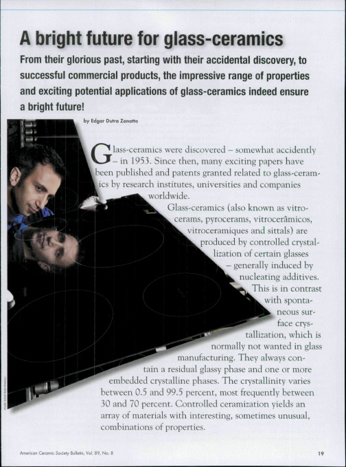
A bright future for glass-ceramics
American Ceramic Society Bulletin, Vol. 89, No. 8
A bright future for glass-ceramics
Unlike sintered ceramics, glassceramics are inherently free from porosity. However, in some cases, bubbles or pores develop during the latter stages of crystallization. Glass-ceramics have, in principle, several advantages. • They can be mass produced by any glass-forming technique. • It is possible to design their nanostructure or microstructure for a given application. • TTiey have zero or very low porosity. • It is possible for them to combine a variety of desired properties. One example of the fourth advantage is combining very low thermal expansion coefficient with transparency in the visible wavelength range for cooking ware. Another is combining \'ery high strength and toughness with translucency, biocompatibility, chemical durability and relatively low hardness for dental applications. Glass-ceramics are normally produced in two steps. First, a glass is formed by a standard glass-manufacturing process. Second, the glass article is shaped, cooled and reheated above its glass transition temperature. The second step is sometimes repeated as a third step. In these heat treatments, the article partly crystallizes in the interior. In most cases, nucleating agents (e.g., noble metals, fluorides, ZrO,, TiO^,
各专业检索常用英语集锦

生物和环境1. 神经的凋亡Apoptosisi of Neuron2. 肌动蛋白myosin的构象及作用机制The Structure and Function of Myosin3. 钇激光器的发射特性Yb Llaser Radiation Character4. 胰酶分泌素的分泌机制The Secreting Mechanism of Cholecystokinin5. 钙离子在信号传导中的作用The Function of Calcium in Signal Transduction6. 1,5-二磷酸核酮糖羧化酶的进化过程The Evolution of Rubisco7. 质谱技术在生物学中的应用Application of Mass Spectrometry in Biology8. PHB的微生物合成The Synthesis of PHB in Bacteria9. HIV-1 的研究Research on HIV-110.STA T信号通路在人体免疫系统的作用The Function of STA T s (Signal Transducers and Activators of Transcription)Involving the Human Immunological System11.水处理中的反渗透膜Reverse Osmosis in Water Treatment12.水体富营养化研究Research on Water Eutrophication13.饮用水处理和生产Drinking Water Treatment and Production14.废水中重金属的去除Removal of Heavy Metal in Waste Water15.膜分离技术在废水处理中的应用Membrane T echnology in the Use of Waste Water Treatment16.废塑料的生物降解Biodegradation of Wasted Plastics17.有机化合物的生物降解能力的确定方法The Method for the Determination of the Biodegradability of Organic Compounds 18.TiO2光催化氧化技术在环境工程中应用Application of Titanium Dioxide Photocatalysis in Environmental Engineering 19.包装材料的回收利用Reuse (Recycle) of Packaging Materials20.水处理中氮的去除The Removal of Nitrogen in Water-treatment21.污水的生物处理Biological Treatment of Waste Water22.催化还原法去除废气中的氮氧化物(NOx)The Catalytic Processes to Reduce Nitrogen Oxide in Waste Gases23.大气质量模型Atmosphere Environmental Quality Model24.挥发性有机物的测量The Measurement of the V olatile Organic Chemicals25.UASB在废水处理中的应用Application of UASB (Upflow Anaerobic Sludge Blanket) Reactor for the Treatment of Waste Water26.纺织工业废水中染料的去除The Removal of the Dyes from Waste Water of T extile Industry27.复合PCR技术在基因重组中的应用Multiplex PCR in Genetic Rearrangement28.含多环芳香烃废水对环境的污染The Pollution of Waste Water Containing Polycyclic Aromatic Hydrocarbons29.高效生物反应器的发展Development of High Performance Biotreator30.应用高效液相色谱纯化生物分子Purification of Biomolecules by HPLC (High-performance Liquid Chromatography) 31.蓝藻中的膜脂成分分析Analysis of Membrane Lipids in Cyanobacteria32.b-amyloid 在老年痴呆症中对神经的作用Function of b-amyloid on Neuron in Alzheimer's Disease33.小鼠胚胎干细胞的培养Cultivation of Embryonic Stem Cells in Mice34.基质金属蛋白酶的抑制Inhibition of Matrix Metalloproteinase (MMP)35.生物医用亲合吸附剂的研究进展Progress in biomedical affinity adsorbent36.面向环境的土壤磷素测定与表征方法研究进展Review on environmental oriented soil phosphorus testing procedure andinterpreting method37.海水养殖对沿岸生态环境影响的研究进展Review on effects of mariculture on coastal environment38.造纸清洁生产的研究进展Recent studies on cleaning production in paper industry39.深度氧化技术处理有机废水的研究进展Progress on treatment of organic wastewater by advances oxidation processes 40.折流式厌氧反应器(ABR)的研究进展Research advances in anaerobic baffled reactor (ABR)41.膜生物反应器中膜污染研究进展Study progress on the fouling of membrane in membrane bioreactor42.用于水和废水处理的混凝剂和絮凝剂的研究进展Progress on development and application of coagulants and flocculent in water and wastewater treatment43.二氢异香豆素类天然物的研究进展Development of studies on 3,4-dihydroisocoumarins in nature44.天然二萜酚类化合物研究进展Recent advances in the research on natural phenolic diterpenoids45.大气污染化学研究进展Progress in atmospheric chemistry of air pollution46.砷形态分析方法研究进展Development of methods for arsenic speciation47.复合污染的研究进展Advance in the study on compounded pollutions48.生物处理含氯代脂肪烃废水的研究进展Progress in research on the biological treatment of wastewater containingchlorinated aliphatics49.重金属生物吸附剂的应用研究现状Application conditions of heavy metal biosorbent50.两液相培养中有机溶剂对细胞毒性的研究进展Advances in studies on effects of toxicity of organic solvents on cells化学和化工1. 纳米材料的进展及其在塑料中的应用rogress and application of nano-materials in plastics2. 聚硅氯化铝(PASC)混凝剂的混凝特性The Coagulation Property of Polyaluminum Silicate Chlorate (PASC)3. 碳纳米管的制备与研究Preparations and studies of carbon nanotubes4. 纳米材料的制备及其发展动态Synthesis and development of nanosized materials5. 铁(III)核苷酸配位化合物与转铁蛋白的相互作用The interaction between ferric nucleotide coordination compounds and transferrin 6. 原位时间分辨拉曼光谱研究电化学氧化还原和吸附过程In-situ time resolved Raman spectroscopic studied on electrochemical oxidation-reduction and adsorption7. 苯胺电化学聚合机理的研究Study on the mechanism of electrochemical polymerization of aniline8. 沸石新材料研究进展Evolution of novel zeolite materials9. 聚合物共混相容性研究进展Research progress in compatibility of polymer blends10.聚酰亚胺LB膜研究进展Recent advances in polymide langmuir-blodgett films11.聚胺酯液晶研究进展The advances in LC-polyurethanes12.热塑性IPN研究进展及相结构理论Advances in thermoplastic IPN and morphological studies13.酞菁类聚合物功能材料研究进展Progresses in functional materials of phthalocyanine polymers14.有机硒化学研究进展Study progress in organoselenium chemisty15.杯芳烃研究进展Research progress in calixarene chemistry16.木素生物降解的研究进展Research progresses on lignin biodegradation17.甲烷直接催化转化制取芳烃的研究进展Progress research on direct catalytic conversion of methane to aromatics 18.铝基复合材料连接研究进展Advance in joining aluminum metal matrix composites19.现代天然香料提取技术的研究进展New development of the extraction from natural fragrance and flavour20.电泳涂料的研究进展Progress of study on electrodeposition coatings21.防静电涂料研究进展Research progress in antistatic coatings22.壳聚糖开发与应用研究进展Progress in research on the application and production of chitosan23.塑料薄膜防雾化技术的研究进展Research progress of anti-fogging technologies for plastics films24.膜反应器在催化反应中的研究进展Progress in study of films reactors for catalytical reactions25.表面活性剂对结晶过程影响的研究进展The development of studies on the influence of surfactants on crystallization 26.液晶复合分离膜及其研究进展Advances in liquid crystal composite membrane for separation27.高倍吸水树脂研究进展Recent progress in super adsorbent resin28.聚合物光折变的研究进展Progress of the study on photorefractivity in polymers29.微生物聚酯的合成和应用研究进展Progress on the biosynthesis and application of microbial polyesters30.可降解塑料的研究进展Progress in study on degradable plastics31.金属氢研究进展Progress on metallic hydrogen research32.软磁性材料的最新进展Recent advances in hard and soft magnetic materials33.光敏聚酰亚胺的研究进展Development of studies on photosensitive polyimides34.高分子卟啉及其金属配合物的研究进展Advances in polymers of porphyrins and their complexes35.水性聚胺酯研究进展Recent development of waterborne polyurethanes36.C60的研究进展及其在含能材料方面的应用前景Application prospect of C60 in energetic materials37.滤膜溶解富集方法研究进展Progress in investigation of concentration by means of soluble-membrane filter 38.人工晶体研究进展及应用前景The research progress and application prospects of synthetic crystals39.钛硅催化材料的研究进展Development of titanium silicon catalytic materials40.环烯烃聚合物的合成和应用研究进展Progress of polymerization and copolymerization with ethylene of cyclooelfines 41.多孔炭的纳米结构及其解析Nanostructure and analysis of porous carbons42.羰化法合成a-芳基丙酸研究进展Progress in preparation of a-arylpropionic acids through catalytic carbonation 44.组织工程相关生物材料表面工程的研究进展Advances in research on surface engineering of biomaterials for tissueengineering45.表面波在表面活性剂流变学研究中的应用Surface rheological properties of surfactant studied by surface wave technique 46.水溶性高分子聚集行为荧光非辐射能量转移研究进展Development of Fluorescence Nonradiative Energy Transfer in the Research for Aggregation of Water-Soluble Polymers47.两相催化体系中长链烯烃氢甲酰化反应研究进展Advance in the Hydroformylation of Higher Olefin in Two-Phase Catalystic System 48.聚合物膜燃料电池用电催化剂研究进展Progress in the Study of Electrocatalyst for PEMFC49.纳米器件制备的新方法--微接触印刷术New nano-fabrication Method-Microcontact Printing50.智能型水凝胶结构及响应机理的研究进展Recent Development of the Research on the Structure Effects and ResponsiveMechanism of Intelligent Hydrogels51.甲醇蒸馏distillation of methanol电类1. Amplifiers 放大器2. Asynchronous transfer mode(A TM) 异步传输模式3. Aritificial reality 虚拟现实4. Bayesian classification 贝叶斯分类器5. Biped robot 两足机器人6. Cable modem 有线调制解调器7. CDMA mobile communication system 码分多址移动通信系统8. Chaotic neural network 混沌神经网络9. Code optimization 代码优化10. Communication switching 通信交换11. Computer aided design 计算机辅助设计12. Compiler optimisation techniques 编译优化技术13. Computer game design 计算机游戏设计14. Computer graphics 计算机图形学15. Computer network 计算机网络16. Computer simulation 计算机仿真17. Computer vision 计算机视觉18. Continuous speech recognition 连续语音识别19. Corner Detect Operator 边角检测算子20. Database application 数据库应用21. Design of operation system 操作系统设计22. Digital filter 数字滤波器23. Digital image processing 数字图像处理24. Digital integrated circuits 数字集成电路25. Digital satellite communication system 数字卫星通信系统26. Digital signal processing 数字信号处理27. Digital television technology 数字电视技术28. Discrete system simulator programming 离散系统仿真编程29. Distributed interactive learning environment 分布式交互性学习环境30. EDA 数字系统设计自动化31. Electrical vehicles 电动交通工具32. Electricity control system 电力控制系统33. Electromagenetic wave radiation 电磁波辐射34. Face recognition 人脸识别35. Family Automation 家庭自动化36. Fibre bragg gratings 光纤布拉格光栅37. FIR digital filters 有限冲击响应数字滤波器38. Firewall technology 防火墙技术39. Fuzzy control 模糊控制40. Genetic algorithm 遗传算法41. HDTV 高清晰度电视42. High capacity floppy disk 高密度软盘43. High quality speech communication 高质量语音通信44. Image compression 图像压缩45. Image processing and recognition 图像处理和识别46. Image registration 图像配准47. Information retrieval 信息检索48. Intelligent robot 智能机器人49. Intelligent transportation 智能交通50. Internet protocol 因特网协议51. ISDN 综合业务数字网52. Knowledge discovery and data mining 知识发现和数据挖掘53. LAN, MAN and W AN 局域网,城域网和广域网54. Large scale integrated circuits 大规模集成电路55. Laser diode 激光二极管56. Laser measurement 激光测量57. Liner programming 线性规划58. Liner system stability analysis 线性系统稳定性分析59. Local area network security 局域网安全60. Magnetic material and devices 磁介质与设备61. Mass storage systems 海量存储技术62. Microwave devices 微波器件63. Mobile communication systems 移动通信系统64. MOS circuits MOS电路65. Motion control of robot 机器人运动控制66. Multimedia network 多媒体网络67. Network computing and knowledge acquisition 网络计算和知识获取68. Network routing protocol test 网络路由协议测试69. Neural network 神经网络70. Non-linear control 非线性控制71. Optical communication 光通信72. Optical fiber amplifiers 光纤放大器73. Optical hologram storage 光全息存储74. Optical modification 光调制75. Optical sensors 光传感器76. Optical switches 光开关77. Optical waveguides 光波导78. Packet switching technology in networks 网络中的分组交换技术79. Parallel algorithms 并行算法80. Pattern recognition 模式识别81. Photoelectric devices 光电子器件82. Process identificaion 过程辨识83. Programmable DSP chips 可编程数字信号处理芯片84. Programmable logic device 可编程逻辑器件85. Radar antennas 雷达天线86. Radar theory and systems 雷达理论和系统87. RISC architecture 简单指令处理器结构88. Satellite broadcasting 卫星广播89. Self calibration of camera 摄像机自适应校准90. Semiconductor laser 半导体激光器91. Semiconductor quantum well superlattices 半导体量子阱超晶格92. Signal detection and analysis 信号检测和分析93. Signal processing 信号处理94. Software engineering 软件工程95. Solid lasers 固体激光器96. Sound synthesiser 声音合成器97. Speech processing 语音处理98. System architecture design 系统结构设计99. Telecommunication receiving equipment 通信接收设备100. Theory of remote sensing by radar 雷达遥感理论101. Time division multiple access 时分多路访问102. Unix operating system Unix操作系统103. Video encoding and decoding 视频编解码104. Video telecommunication system 视频通信系统105. Wavelength division multiplexing 波分复用106. Wavelet transform 小波变换机械、自动化、物理、力学1. 无电压力传感器Nonelectric Pressure Sensors2. 金属腐蚀Metal Corrosion3. 印刷电路板的设计与制造The Design and Manufactory of Printed Circuit Board4. 分布式操作系统Distributed Operating Systems5. 金属材料的微结构和纳米结构Micro and Nanostructures of metal materials6. 宇宙背景辐射Backgroud Cosmic Radiations7. 非线性规划中的库恩-塔克条件kuhn-Tucker condition in Non-liner Programming8. 气体激光器Gas Laser9. 能量的来源及转化Energy resources and conversion10. 微纳米摩擦学Micro/nano-tribology11. 噪声控制Noise Control12. 空间观测技术Astronomical observation techniques13. 原子钟Atomic Clocks14. 半导体的磁性研究Research for Magnetic of Semiconductors15. 光学图形处理Optical Image Processing16. 液体/气体激光器加工Liquid/Gas Laser Machining17. 太阳能应用Solar Energy Application18. 流动系统中的混沌现象Chaos in Flowing Systems19. 半导体材料及仪器Semiconductor material and devices20. 电场测量研究Electric Field Measurement21. 系统及控制理论Systems and Control Theory22. 机械参量的测试Mechanical variables Measurement23. 光纤Optical Fibres24. 机动目标跟踪Tracking of Maneuvering T argets25. 航天技术Aerospace T echnology26. 导弹跟踪控制系统Missile Tracking System27. 液晶显示器件Liquid Crystal Displays28. CMOS 门电路CMOS Gate Circuits29. 图象采样与处理Image Sampling and Processing30. 光逻辑器件Optical Logic Device31. 信号发生器Signal Generator32. 蛋白质晶体测量Measurement of Protein Crystal Growth33. 有线电视Cables T elevision34. 震动与控制系统Vibration and Control System35. 高压输电系统的安全性研究Stability of High-voltage Power TransmissionSystem36. 电荷Electric Charge37. 电子显微镜及电子光学应用Electron Microscopes an Optics Applications38. 辐射的影响The Effect of Radiation39. 电化学传感器测试装置Electronchemical Sensors T esting Equipment40. 爱因斯坦-麦克斯韦场Einstein-Maxwell Fields41. 柔性角度传感器在生物力学中的应用Biomechanical Application of Flesible Angular Sensor42. 压电材料及应用装置Piezoelectric Materials and Devices43. 超导材料及其应用Superconducting Materials and The Applications of Them44. 光学干涉Optical Interferometry45. 表面测量Surface Measurement46. 等离子体中的电磁波Electromagnetic Waves in Plasma47. 半导体激光器Semiconductor lasers48. 数字人脸辨识Digital Face Recognition49. 光波导Optical Waveguides Theory50. 机械波检测技术Mechanical Waves T esting technology51. 激光调制技术Laser beam Modulation T echnology52. 只读内存Read-only Memory53. 光学显微镜Optical Microscopy54. 光纤位移测量传感器F-O displacement sensors55. 激光扫描Laser Scanners56. 量子论与量子场论Quantum Theory and Quantum Field Theory57. 流体机械Fluid Mechanics58. 地球引力Earth Gravity59. 自动控制系统Automatic Control System60. 静电线性加速器Electrostatic and Linear Accelerators61. 专家系统与网络接口Expert Systems and Network Interface62. 计算机辅助制造Computer aided Manufacture63. 全息存储Holography Storage64. 核能在中国的前景The Future of Nuclear Energy in China65. 机器人运动学和动力学分析The Kinematics an Dynamics of Robots66. 合成材料制品Composite Materials Preparations67. 光的吸收Light Absorption68. 自适应控制系统Self-adjusting Control Systems69. 通信与信息系统Communication and Information Systems70. 数字信号处理芯片Digital Signal Processing Chips71. 虚拟制造Virtual Manufacturing72. 雷达遥感Remote Sensing by Radar73. 晶格理论与点阵统计学Lattice Theory and Statistics74. 面向对象程序设计Object-Oriented Program Development75. 单片机应用及其外围设备The Applications of SCP and Outer Equipment76. 生物医学工程Biomedical Engineering77. 彩色电视设备Color T elevision78. 陶瓷-金属复合材料Ceramics-metallisation Composite Metallisation79. 电子信号的检测与处理Electronic Signal Detection and Processing80. X射线望远镜X- ray T elescope81. 基于网络的分时控制系统Time-varying Control System Based on Network82. 收音机信号传输Radio Broadcasting83. 单壁炭纳米管合成Single-Walled Carbon Nanotube Synthesis84. 无损检测Nondestructive T esting85. 汽车工业Automobile Industry86. 半导体材料与身体健康Semiconductor Materials and Health Physics87. 热辐射Heat Radiation88. 网络拓扑学Network T opology89. 微波的应用The Application of Microwave90. 局域网的设计The Design of Local Area Networks91. 金属元素表面结构Surface Structure of Metallic Elements92. 多媒体系统网络集成Network Synthesis of Multimedia Systems93. 铁氧体微波吸收材料Ferrite Microwave Absorbing Materials94. 炭纤维增强塑料复合材料Carbon Fiber Reinforced Plastic Composite95. 超导材料Superconducting Materials96. 远程定位水质控制Remote and On-site System for Water Quality Control97. 太阳能电力系统Solar Energy Power System98. 卫星接收系统Satellite Broadcasting and Relay System99. 时空对称性与守恒定律Symmetry of Space-time and Conservation Laws 100.邮件系统的体系及应用Application and Schemas for Mailbox System。
镍柱纯化蛋白说明书

Instruction ManualProBond TM Purification SystemFor purification of polyhistidine-containing recombinant proteinsCatalog nos. K850-01, K851-01, K852-01, K853-01, K854-01,R801-01, R801-15Version K2 September200425-0006iiTable of ContentsKit Contents and Storage (iv)Accessory Products (vi)Introduction (1)Overview (1)Methods (2)Preparing Cell Lysates (2)Purification Procedure—Native Conditions (7)Purification Procedure—Denaturing Conditions (11)Purification Procedure—Hybrid Conditions (13)Troubleshooting (15)Appendix (17)Additional Protocols (17)Recipes (18)Frequently Asked Questions (21)References (22)Technical Service (23)iiiKit Contents and StorageTypes of Products This manual is supplied with the following products:Product CatalogNo.ProBond™ Purification System K850-01ProBond™ Purification System with Antibodywith Anti-Xpress™ Antibody K851-01with Anti-myc-HRP Antibody K852-01with Anti-His(C-term)-HRP Antibody K853-01with Anti-V5-HRP Antibody K854-01ProBond™ Nickel-Chelating Resin (50 ml) R801-01ProBond™ Nickel Chelating Resin (150 ml) R801-15ProBond™Purification System Components The ProBond™ Purification System includes enough resin, reagents, and columns for six purifications. The components are listed below. See next page for resin specifications.Component Composition Quantity ProBond™ Resin 50% slurry in 20% ethanol 12 ml5X NativePurification Buffer250 mM NaH2PO4, pH 8.02.5 M NaCl1 × 125 ml bottleGuanidinium LysisBuffer6 M Guanidine HCl20 mM sodium phosphate, pH 7.8500 mM NaCl1 × 60 ml bottleDenaturingBinding Buffer8 M Urea20 mM sodium phosphate, pH 7.8500 mM NaCl2 × 125 ml bottlesDenaturing WashBuffer8 M Urea20 mM sodium phosphate, pH 6.0500 mM NaCl2 × 125 ml bottlesDenaturing ElutionBuffer8 M Urea20 mM NaH2PO4, pH 4.0500 mM NaCl1 × 60 ml bottleImidazole 3 M Imidazole,20 mM sodium phosphate, pH 6.0500 mM NaCl1 × 8 ml bottlePurificationColumns10 ml columns 6Continued on next pageivKit Contents and Storage, ContinuedProBond™Purification System with Antibody The ProBond™ Purification System with Antibody includes resin, reagents, and columns as described for the ProBond™ Purification System (previous page) and 50 µl of the appropriate purified mouse monoclonal antibody. Sufficient reagents are included to perform six purifications and 25 Western blots with the antibody.For more details on the antibody specificity, subclass, and protocols for using the antibody, refer to the antibody manual supplied with the system.Storage Store ProBond™ resin at +4°C. Store buffer and columns at room temperature.Store the antibody at 4°C. Avoid repeated freezing and thawing of theantibody as it may result in loss of activity.The product is guaranteed for 6 months when stored properly.All native purification buffers are prepared from the 5X Native PurificationBuffer and the 3 M Imidazole, as described on page 7.The Denaturing Wash Buffer pH 5.3 is prepared from the Denaturing WashBuffer (pH 6.0), as described on page 11.Resin and ColumnSpecificationsProBond™ resin is precharged with Ni2+ ions and appears blue in color. It isprovided as a 50% slurry in 20% ethanol.ProBond™ resin and purification columns have the following specifications:• Binding capacity of ProBond™ resin: 1–5 mg of protein per ml of resin• Average bead size: 45–165 microns• Pore size of purification columns: 30–35 microns• Recommended flow rate: 0.5 ml/min• Maximum flow rate: 2 ml/min• Maximum linear flow rate: 700 cm/h• Column material: Polypropylene• pH stability (long term): pH 3–13• pH stability (short term): pH 2–14ProductQualificationThe ProBond™ Purification System is qualified by purifying 2 mg of myoglobinprotein on a column and performing a Bradford assay. Protein recovery mustbe 75% or higher.vAccessory ProductsAdditionalProductsThe following products are also available for order from Invitrogen:Product QuantityCatalogNo.ProBond™ Nickel-Chelating Resin 50 ml150 mlR801-01R801-15Polypropylene columns(empty)50 R640-50Ni-NTA Agarose 10 ml25 ml R901-01 R901-15Ni-NTA Purification System 6 purifications K950-01 Ni-NTA Purification Systemwith Antibodywith Anti-Xpress™ Antibody with Anti-myc-HRP Antibody with Anti-His(C-term)-HRP Antibodywith Anti-V5-HRP Antibody 1 kit1 kit1 kit1 kitK951-01K952-01K953-01K954-01Anti-myc Antibody 50 µl R950-25 Anti-V5 Antibody 50 µl R960-25 Anti-Xpress™ Antibody 50 µl R910-25 Anti-His(C-term) Antibody 50 µl R930-25 InVision™ His-tag In-gel Stain 500 ml LC6030 InVision™ His-tag In-gelStaining Kit1 kit LC6033Pre-Cast Gels and Pre-made Buffers A large variety of pre-cast gels for SDS-PAGE and pre-made buffers for your convenience are available from Invitrogen. For details, visit our web site at or contact Technical Service (page 23).viIntroductionOverviewIntroduction The ProBond™ Purification System is designed for purification of 6xHis-tagged recombinant proteins expressed in bacteria, insect, and mammalian cells. Thesystem is designed around the high affinity and selectivity of ProBond™Nickel-Chelating Resin for recombinant fusion proteins containing six tandemhistidine residues.The ProBond™ Purification System is a complete system that includespurification buffers and resin for purifying proteins under native, denaturing,or hybrid conditions. The resulting proteins are ready for use in many targetapplications.This manual is designed to provide generic protocols that can be adapted foryour particular proteins. The optimal purification parameters will vary witheach protein being purified.ProBond™ Nickel-Chelating Resin ProBond™ Nickel-Chelating Resin is used for purification of recombinant proteins expressed in bacteria, insect, and mammalian cells from any 6xHis-tagged vector. ProBond™ Nickel-Chelating Resin exhibits high affinity and selectivity for 6xHis-tagged recombinant fusion proteins.Proteins can be purified under native, denaturing, or hybrid conditions using the ProBond™ Nickel-Chelating Resin. Proteins bound to the resin are eluted with low pH buffer or by competition with imidazole or histidine. The resulting proteins are ready for use in target applications.Binding Characteristics ProBond™ Nickel-Chelating Resin uses the chelating ligand iminodiacetic acid (IDA) in a highly cross-linked agarose matrix. IDA binds Ni2+ ions by three coordination sites.The protocols provided in this manual are generic, and may not result in 100%pure protein. These protocols should be optimized based on the bindingcharacteristics of your particular proteins.Native VersusDenaturingConditionsThe decision to purify your 6xHis-tagged fusion proteins under native ordenaturing conditions depends on the solubility of the protein and the need toretain biological activity for downstream applications.• Use native conditions if your protein is soluble (in the supernatant afterlysis) and you want to preserve protein activity.• Use denaturing conditions if the protein is insoluble (in the pellet afterlysis) or if your downstream application does not depend on proteinactivity.• Use hybrid protocol if your protein is insoluble but you want to preserveprotein activity. Using this protocol, you prepare the lysate and columnsunder denaturing conditions and then use native buffers during the washand elution steps to refold the protein. Note that this protocol may notrestore activity for all proteins. See page 14.1MethodsPreparing Cell LysatesIntroduction Instructions for preparing lysates from bacteria, insect, and mammalian cellsusing native or denaturing conditions are described below.Materials Needed You will need the following items:• Native Binding Buffer (recipe is on page 8) for preparing lysates undernative conditions• Sonicator• 10 µg/ml RNase and 5 µg/ml DNase I (optional)• Guanidinium Lysis Buffer (supplied with the system) for preparing lysatesunder denaturing conditions• 18-gauge needle• Centrifuge• Sterile, distilled water• SDS-PAGE sample buffer• Lysozyme for preparing bacterial cell lysates• Bestatin or Leupeptin, for preparing mammalian cell lysatesProcessing Higher Amount of Starting Material Instructions for preparing lysates from specific amount of starting material (bacteria, insect, and mammalian cells) and purification with 2 ml resin under native or denaturing conditions are described in this manual.If you wish to purify your protein of interest from higher amounts of starting material, you may need to optimize the lysis protocol and purification conditions (amount of resin used for binding). The optimization depends on the expected yield of your protein and amount of resin to use for purification. Perform a pilot experiment to optimize the purification conditions and then based on the pilot experiment results, scale-up accordingly.Continued on next page2Preparing Bacterial Cell Lysate—Native Conditions Follow the procedure below to prepare bacterial cell lysate under native conditions. Scale up or down as necessary.1. Harvest cells from a 50 ml culture by centrifugation (e.g., 5000 rpm for5 minutes in a Sorvall SS-34 rotor). Resuspend the cells in 8 ml NativeBinding Buffer (recipe on page 8).2. Add 8 mg lysozyme and incubate on ice for 30 minutes.3. Using a sonicator equipped with a microtip, sonicate the solution on iceusing six 10-second bursts at high intensity with a 10-second coolingperiod between each burst.Alternatively, sonicate the solution on ice using two or three 10-secondbursts at medium intensity, then flash freeze the lysate in liquid nitrogen or a methanol dry ice slurry. Quickly thaw the lysate at 37°C andperform two more rapid sonicate-freeze-thaw cycles.4. Optional: If the lysate is very viscous, add RNase A (10 µg/ml) andDNase I (5 µg/ml) and incubate on ice for 10–15 minutes. Alternatively,draw the lysate through a 18-gauge syringe needle several times.5. Centrifuge the lysate at 3,000 ×g for 15 minutes to pellet the cellulardebris. Transfer the supernatant to a fresh tube.Note: Some 6xHis-tagged protein may remain insoluble in the pellet, and can be recovered by preparing a denatured lysate (page 4) followed bythe denaturing purification protocol (page 12). To recover this insolubleprotein while preserving its biological activity, you can prepare thedenatured lysate and then follow the hybrid protocol on page 14. Notethat the hybrid protocol may not restore activity in all cases, and should be tested with your particular protein.6. Remove 5 µl of the lysate for SDS-PAGE analysis. Store the remaininglysate on ice or freeze at -20°C. When ready to use, proceed to theprotocol on page 7.Continued on next page3Preparing Bacterial Cell Lysate—Denaturing Conditions Follow the procedure below to prepare bacterial cell lysate under denaturing conditions:1. Equilibrate the Guanidinium Lysis Buffer, pH 7.8 (supplied with thesystem or see page 19 for recipe) to 37°C.2. Harvest cells from a 50 ml culture by centrifugation (e.g., 5000 rpm for5 minutes in a Sorvall SS-34 rotor).3. Resuspend the cell pellet in 8 ml Guanidinium Lysis Buffer from Step 1.4. Slowly rock the cells for 5–10 minutes at room temperature to ensurethorough cell lysis.5. Sonicate the cell lysate on ice with three 5-second pulses at high intensity.6. Centrifuge the lysate at 3,000 ×g for 15 minutes to pellet the cellulardebris.Transfer the supernatant to a fresh tube.7. Remove 5 µl of the lysate for SDS-PAGE analysis. Store the remaininglysate on ice or at -20°C. When ready to use, proceed to the denaturingprotocol on page 11 or hybrid protocol on page 13.Note: To perform SDS-PAGE with samples in Guanidinium Lysis Buffer, you need to dilute the samples, dialyze the samples, or perform TCAprecipitation prior to SDS-PAGE to prevent the precipitation of SDS.Harvesting Insect Cells For detailed protocols dealing with insect cell expression, consult the manual for your particular system. The following lysate protocols are for baculovirus-infected cells and are intended to be highly generic. They should be optimized for your cell lines.For baculovirus-infected insect cells, when the time point of maximal expression has been determined, large scale protein expression can be carried out. Generally, the large-scale expression is performed in 1 liter flasks seeded with cells at a density of 2 × 10⁶ cells/ml in a total volume of 500 ml and infected with high titer viral stock at an MOI of 10 pfu/cell. At the point of maximal expression, harvest cells in 50 ml aliquots. Pellet the cells by centrifugation and store at -70°C until needed. Proceed to preparing cell lysates using native or denaturing conditions as described on the next page.Continued on next page4Preparing Insect Cell Lysate—Native Condition 1. Prepare 8 ml Native Binding Buffer (recipe on page 8) containingLeupeptin (a protease inhibitor) at a concentration of 0.5 µg/ml.2. After harvesting the cells (previous page), resuspend the cell pellet in8 ml Native Binding Buffer containing 0.5 µg/ml Leupeptin.3. Lyse the cells by two freeze-thaw cycles using a liquid nitrogen or dryice/ethanol bath and a 42°C water bath.4. Shear DNA by passing the preparation through an 18-gauge needle fourtimes.5. Centrifuge the lysate at 3,000 ×g for 15 minutes to pellet the cellulardebris.Transfer the supernatant to a fresh tube.6. Remove 5 µl of the lysate for SDS-PAGE analysis. Store remaining lysateon ice or freeze at -20°C. When ready to use, proceed to the protocol on page 7.Preparing Insect Cell Lysate—Denaturing Condition 1. After harvesting insect cells (previous page), resuspend the cell pellet in8 ml Guanidinium Lysis Buffer (supplied with the system or see page 19for recipe).2. Pass the preparation through an 18-gauge needle four times.3. Centrifuge the lysate at 3,000 ×g for 15 minutes to pellet the cellulardebris. Transfer the supernatant to a fresh tube.4. Remove 5 µl of the lysate for SDS-PAGE analysis. Store remaining lysateon ice or freeze at -20° C. When ready to use, proceed to the denaturingprotocol on page 11 or hybrid protocol on page 13.Note: To perform SDS-PAGE with samples in Guanidinium Lysis Buffer, you need to dilute the samples, dialyze the samples, or perform TCAprecipitation prior to SDS-PAGE to prevent the precipitation of SDS.Continued on next pagePreparing Mammalian Cell Lysate—Native Conditions For detailed protocols dealing with mammalian expression, consult the manual for your particular system. The following protocols are intended to be highly generic, and should be optimized for your cell lines.To produce recombinant protein, you need between 5 x 10⁶and 1 x 10⁷ cells. Seed cells and grow in the appropriate medium until they are 80–90% confluent. Harvest cells by trypsinization. You can freeze the cell pellet in liquid nitrogen and store at -70°C until use.1. Resuspend the cell pellet in 8 ml of Native Binding Buffer (page 8). Theaddition of protease inhibitors such as bestatin and leupeptin may benecessary depending on the cell line and expressed protein.2. Lyse the cells by two freeze-thaw cycles using a liquid nitrogen or dryice/ethanol bath and a 42°C water bath.3. Shear the DNA by passing the preparation through an 18-gauge needlefour times.4. Centrifuge the lysate at 3,000 ×g for 15 minutes to pellet the cellulardebris. Transfer the supernatant to a fresh tube.5. Remove 5 µl of the lysate for SDS-PAGE analysis. Store the remaininglysate on ice or freeze at -20° C. When ready to use, proceed to theprotocol on page 7.Preparing Mammalian Cell Lysates—Denaturing Conditions For detailed protocols dealing with mammalian expression, consult the manual for your particular system. The following protocols are intended to be highly generic, and should be optimized for your cell lines.To produce recombinant protein, you need between 5 x 10⁶and 1 x 10⁷ cells. Seed cells and grow in the appropriate medium until they are 80–90% confluent. Harvest cells by trypsinization. You can freeze the cell pellet in liquid nitrogen and store at -70°C until use.1. Resuspend the cell pellet in 8 ml Guanidinium Lysis Buffer (suppliedwith the system or see page 19 for recipe).2. Shear the DNA by passing the preparation through an 18-gauge needlefour times.3. Centrifuge the lysate at 3,000 ×g for 15 minutes to pellet the cellulardebris. Transfer the supernatant to a fresh tube.4. Remove 5 µl of the lysate for SDS-PAGE analysis. Store the remaininglysate on ice or freeze at -20° C until use. When ready to use, proceed to the denaturing protocol on page 11 or hybrid protocol on page 13.Note: To perform SDS-PAGE with samples in Guanidinium Lysis Buffer, you need to dilute the samples, dialyze the samples, or perform TCAprecipitation prior to SDS-PAGE to prevent the precipitation of SDS.Purification Procedure—Native ConditionsIntroduction In the following procedure, use the prepared Native Binding Buffer, NativeWash Buffer, and Native Elution Buffer, columns, and cell lysate preparedunder native conditions. Be sure to check the pH of your buffers before starting.Buffers for Native Purification All buffers for purification under native conditions are prepared from the5X Native Purification Buffer supplied with the system. Dilute and adjust the pH of the 5X Native Purification Buffer to create 1X Native Purification Buffer (page 8). From this, you can create the following buffers:• Native Binding Buffer• Native Wash Buffer• Native Elution BufferThe recipes described in this section will create sufficient buffers to perform one native purification using one kit-supplied purification column. Scale up accordingly.If you are preparing your own buffers, see page 18 for recipe.Materials Needed You will need the following items:• 5X Native Purification Buffer (supplied with the system or see page 18 forrecipe)• 3 M Imidazole (supplied with the system or see page 18 for recipe)• NaOH• HCl• Sterile distilled water• Prepared ProBond™ columns with native buffers (next page)• Lysate prepared under native conditions (page 2)Imidazole Concentration in Native Buffers Imidazole is included in the Native Wash and Elution Buffers to minimize the binding of untagged, contaminating proteins and increase the purity of the target protein with fewer wash steps. Note that, if your level of contaminating proteins is high, you may add imidazole to the Native Binding Buffer.If your protein does not bind well under these conditions, you can experiment with lowering or eliminating the imidazole in the buffers and increasing the number of wash and elution steps.Continued on next page1X Native Purification Buffer To prepare 100 ml 1X Native Purification Buffer, combine:• 80 ml of sterile distilled water• 20 ml of 5X Native Purification Buffer (supplied with the system or see page 18 for recipe)Mix well and adjust pH to 8.0 with NaOH or HCl.Native Binding Buffer Without ImidazoleUse 30 ml of the 1X Native Purification Buffer (see above for recipe) for use as the Native Binding Buffer (used for column preparation, cell lysis, and binding).With Imidazole (Optional):You can prepare the Native Binding Buffer with imidazole to reduce the binding of contaminating proteins. (Note that some His-tagged proteins may not bind under these conditions.).To prepare 30 ml Native Binding Buffer with 10 mM imidazole, combine: • 30 ml of 1X Native Purification Buffer• 100 µl of 3 M Imidazole, pH 6.0Mix well and adjust pH to 8.0 with NaOH or HCl.Native Wash Buffer To prepare 50 ml Native Wash Buffer with 20 mM imidazole, combine:• 50 ml of 1X Native Purification Buffer• 335 µl of 3 M Imidazole, pH 6.0Mix well and adjust pH to 8.0 with NaOH or HCl.Native Elution Buffer To prepare 15 ml Native Elution Buffer with 250 mM imidazole, combine:• 13.75 ml of 1X Native Purification Buffer• 1.25 ml of 3 M Imidazole, pH 6.0Mix well and adjust pH to 8.0 with NaOH or HCl.Continued on next pageDo not use strong reducing agents such as DTT with ProBond™ columns. DTTreduces the nickel ions in the resin. In addition, do not use strong chelatingagents such as EDTA or EGTA in the loading buffers or wash buffers, as thesewill strip the nickel from the columns.Be sure to check the pH of your buffers before starting.PreparingProBond™ ColumnWhen preparing a column as described below, make sure that the snap-off capat the bottom of the column remains intact. To prepare a column:1. Resuspend the ProBond™ resin in its bottle by inverting and gentlytapping the bottle repeatedly.2. Pipet or pour 2 ml of the resin into a 10-ml Purification Columnsupplied with the kit. Allow the resin to settle completely by gravity(5-10 minutes) or gently pellet it by low-speed centrifugation (1 minuteat 800 ×g). Gently aspirate the supernatant.3. Add 6 ml of sterile, distilled water and resuspend the resin byalternately inverting and gently tapping the column.4. Allow the resin to settle using gravity or centrifugation as described inStep 2, and gently aspirate the supernatant.5. For purification under Native Conditions, add 6 ml Native BindingBuffer (recipe on page 8).6. Resuspend the resin by alternately inverting and gently tapping thecolumn.7. Allow the resin to settle using gravity or centrifugation as described inStep 2, and gently aspirate the supernatant.8. Repeat Steps 5 through 7.Storing PreparedColumnsTo store a column containing resin, add 0.02% azide or 20% ethanol as apreservative and cap or parafilm the column. Store at room temperature.Continued on next pagePurification Under Native Conditions Using the native buffers, columns and cell lysate, follow the procedure below to purify proteins under native conditions:1. Add 8 ml of lysate prepared under native conditions to a preparedPurification Column (page 9).2. Bind for 30–60 minutes using gentle agitation to keep the resinsuspended in the lysate solution.3. Settle the resin by gravity or low speed centrifugation (800 ×g), andcarefully aspirate the supernatant. Save supernatant at 4°C forSDS-PAGE analysis.4. Wash with 8 ml Native Wash Buffer (page 8). Settle the resin by gravityor low speed centrifugation (800 ×g), and carefully aspirate thesupernatant. Save supernatant at 4°C for SDS-PAGE analysis.5. Repeat Step 4 three more times.6. Clamp the column in a vertical position and snap off the cap on thelower end. Elute the protein with 8–12 ml Native Elution Buffer (seepage 2). Collect 1 ml fractions and analyze with SDS-PAGE.Note: Store the eluted fractions at 4°C. If -20°C storage is required, addglycerol to the fractions. For long term storage, add protease inhibitors to the fractions.If you wish to reuse the resin to purify the same recombinant protein, wash the resin with 0.5 M NaOH for 30 minutes and equilibrate the resin in a suitable binding buffer. If you need to recharge the resin, see page 17.Purification Procedure—Denaturing ConditionsIntroduction Instructions to perform purification using denaturing conditions with prepareddenaturing buffers, columns, and cell lysate are described below.Materials Needed You will need the following items:• Denaturing Binding Buffer (supplied with the system or see page 19 forrecipe)• Denaturing Wash Buffer, pH 6.0 (supplied with the system or see page 19 forrecipe) and Denaturing Wash Buffer, pH 5.3 (see recipe below)• Denaturing Elution Buffer (supplied with the system or see page 20 forrecipe)• Prepared ProBond™ columns with Denaturing buffers (see below)• Lysate prepared under denaturing conditions (page 11)Preparing the Denaturing Wash Buffer pH 5.3 Using a 10 ml aliquot of the kit-supplied Denaturing Wash Buffer (pH 6.0), mix well, and adjust the pH to 5.3 using HCl. Use this for the Denaturing Wash Buffer pH 5.3 in Step 5 next page.Be sure to check the pH of your buffers before starting. Note that thedenaturing buffers containing urea will become more basic over time. PreparingProBond™ ColumnWhen preparing a column as described below, make sure that the snap-off capat the bottom of the column remains intact.If you are reusing the ProBond™ resin, see page 17 for recharging protocol.To prepare a column:1. Resuspend the ProBond™ resin in its bottle by inverting and gentlytapping the bottle repeatedly.2. Pipet or pour 2 ml of the resin into a 10-ml Purification Columnsupplied with the kit. Allow the resin to settle completely by gravity(5-10 minutes) or gently pellet it by low-speed centrifugation (1 minuteat 800 ×g). Gently aspirate the supernatant.3. Add 6 ml of sterile, distilled water and resuspend the resin byalternately inverting and gently tapping the column.4. Allow the resin to settle using gravity or centrifugation as described inStep 2, and gently aspirate the supernatant.5. For purification under Denaturing Conditions, add 6 ml of DenaturingBinding Buffer.6. Resuspend the resin by alternately inverting and gently tapping thecolumn.7. Allow the resin to settle using gravity or centrifugation as described inStep 2, and gently aspirate the supernatant. Repeat Steps 5 through 7.Continued on next pagePurification Procedure—Denaturing Conditions, ContinuedPurification Under Denaturing Conditions Using the denaturing buffers, columns, and cell lysate, follow the procedure below to purify proteins under denaturing conditions:1. Add 8 ml lysate prepared under denaturing conditions to a preparedPurification Column (page 11).2. Bind for 15–30 minutes at room temperature using gentle agitation (e.g.,using a rotating wheel) to keep the resin suspended in the lysatesolution. Settle the resin by gravity or low speed centrifugation (800 ×g), and carefully aspirate the supernatant.3. Wash the column with 4 ml Denaturing Binding Buffer supplied with thekit by resuspending the resin and rocking for two minutes. Settle theresin by gravity or low speed centrifugation (800 ×g), and carefullyaspirate the supernatant. Save supernatant at 4°C for SDS-PAGEanalysis. Repeat this step one more time.4. Wash the column with 4 ml Denaturing Wash Buffer, pH 6.0 supplied inthe kit by resuspending the resin and rocking for two minutes. Settle the resin by gravity or low speed centrifugation (800 ×g), and carefullyaspirate the supernatant. Save supernatant at 4°C for SDS-PAGEanalysis. Repeat this step one more time.5. Wash the column with 4 ml Denaturing Wash Buffer pH 5.3 (see recipeon previous page) by resuspending the resin and rocking for 2 minutes.Settle the resin by gravity or low speed centrifugation (800 ×g), andcarefully aspirate the supernatant. Save supernatant at 4°C for SDS-PAGE analysis. Repeat this step once more for a total of two washes with Denaturing Wash Buffer pH 5.3.6. Clamp the column in a vertical position and snap off the cap on thelower end. Elute the protein by adding 5 ml Denaturing Elution Buffersupplied with the kit. Collect 1 ml fractions and monitor the elution bytaking OD280readings of the fractions. Pool the fractions that contain the peak absorbance and dialyze against 10 mM Tris, pH 8.0, 0.1% Triton X-100 overnight at 4°C to remove the urea. Concentrate the dialyzedmaterial by any standard method (i.e., using 10,000 MW cut-off, low-protein binding centrifugal instruments or vacuum concentrationinstruments).If you wish to reuse the resin to purify the same recombinant protein, wash the resin with 0.5 M NaOH for 30 minutes and equilibrate the resin in a suitable binding buffer. If you need to recharge the resin, see page 17.。
硅氧烷化合物的合成与应用进展

材料工程Journal of Materials Engineering第4 9卷 第4期2021年4月 第13-22页Vol. 4 9 No. 4Apr. 2021 pp. 13 — 22硅氧烷化合物的合成与应用进展Research progress in synthesis andapplication of siloxane compounds程玉桥,路双,冯喆,赵文辉,张治婷,赵越(天津工业大学化学与化工学院,天津300387)CHENG Yu-qiao ,T/U Shuang ,FENG Zhe,ZHAO Wen-hui ,ZHANG Zhi-t.ing,ZHAO Yue(School of Chemistry and Chemical Engineering ,TiangongUniversity? Tianjin 300387 , China)摘要:基于硅氧键特点以及不同条件的化学反应是构建结构迥异、性能独特的新型有机/无机硅氧功能材料的重要方法,近年来,引起了学术界的普遍关注。
新型硅氧功能材料兼具有机/无机化合物性质,以其良好的生物相容性、耐高低 温性以及电绝缘性能被广泛应用于众多领域。
本文综述了硅氧烷化合物设计、合成与应用的研究领域及发展现状,重点 介绍线性结构(一维结构)、非线性结构(二维结构)、多面体低聚倍半硅氧烷化合物(三维结构)以及有机/无机杂化硅氧烷化合物的设计及合成方法,并通过研究可拉伸聚硅氧烷弹性体、硅氧烷化合物涂层、新型驱油用硅氧功能材料等多种方式以增进硅氧烷化合物在生物医学、航空航天、功能材料及三次采油方面的应用进展。
关键词:线性结构;非线性结构;多面体低聚倍半硅氧烷;有机/无机杂化硅氧烷化合物;合成方法doi : 10. 11868/. issn. 1001-4381.2020. 000125中图分类号:O613.72文献标识码:A 文章编号:10014381(2021)04-0013-10Abstract : Chemical reactions based on the characteristics of silicon-oxygen bonds and differentconditions are important methods to construct new organic/inorganic siloxane functional materialswith very different structures and unique properties , which have aroused widespread attention in the academic community. The new silicon-oxygen functional materials have both organic/inorganic compound properties , and are widely used in many fields for their good biocompatibility , high and lowtemperature resistance , and electrical insulation properties. The research fields and developmentstatus of the design , synthesis and application of siloxane compounds were reviewed in this paper , focusing on the design and synthesis methods of linear structure (one-dimensional structure ),nonlinear structure (t.wo-climensional structure ) , polyhedral oligomeric silsesquioxane compounds (three-dimensional structure) and organic/inorganic hybrid siloxane compounds , and the application progress of siloxane compounds in biomedicine , aerospace , functional materials and tertiary oilrecovery will be promoted by studying stretchable polysiloxane elastomer , siloxane compound coating , new silicone functional materials for oil displacement and so on.Key words : linear structure ; nonlinear structure ; polyhedral oligomeric silsesquioxane ; organic/inorganic hybrid siloxane compounds ;synthesis method随着材料科学的不断发展,硅氧烷化合物因其良 好的耐热性、生物相容性、高透气性和高绝缘性能在诸 多领域占据着重要地位。
SCI写作句型汇总
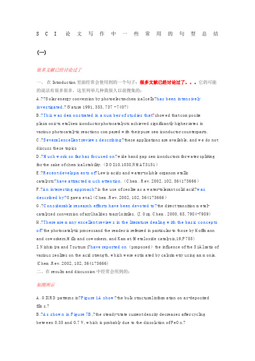
S C I论文写作中一些常用的句型总结(一)很多文献已经讨论过了一、在Introduction里面经常会使用到的一个句子:很多文献已经讨论过了。
它的可能的说法有很多很多,这里列举几种我很久以前搜集的:A.??Solar energy conversion by photoelectrochemical cells?has been intensively investigated.?(Nature 1991, 353, 737 - 740?)B.?This was demonstrated in a number of studies that?showed that composite plasmonic-metal/semiconductor photocatalysts achieved significantly higher rates in various photocatalytic reactions compared with their pure semiconductor counterparts.C.?Several excellent reviews describing?these applications are available, and we do not discuss these topicsD.?Much work so far has focused on?wide band gap semiconductors for water splitting for the sake of chemical stability.(DOI:10.1038/NMAT3151)E.?Recent developments of?Lewis acids and water-soluble organometalliccatalysts?have attracted much attention.(Chem. Rev. 2002, 102, 3641?3666)F.?An interesting approach?in the use of zeolite as a water-tolerant solid acid?was described by?Ogawa et al(Chem.Rev. 2002, 102, 3641?3666)G.?Considerable research efforts have been devoted to?the direct transition metal-catalyzed conversion of aryl halides toaryl nitriles. (J. Org. Chem. 2000, 65, 7984-7989) H.?There are many excellent reviews in the literature dealing with the basic concepts of?the photocatalytic processand the reader is referred in particular to those by Hoffmann and coworkers,Mills and coworkers, and Kamat.(Metal oxide catalysis,19,P755)I. Nishimiya and Tsutsumi?have reported on(proposed)the influence of the Si/Al ratio of various zeolites on the acid strength, which were estimated by calorimetry using ammonia. (Chem.Rev. 2002, 102, 3641?3666)二、在results and discussion中经常会用到的:如图所示A. GIXRD patterns in?Figure 1A show?the bulk structural information on as-deposited films.?B.?As shown in Figure 7B,?the steady-state current density decreases after cycling between 0.35 and 0.7 V, which is probably due to the dissolution of FeOx.?C.?As can be seen from?parts a and b of Figure 7, the reaction cycles start with the thermodynamically most favorable VOx structures(J. Phys. Chem. C 2014, 118, 24950?24958)这与XX能够相互印证:A.?This is supported by?the appearance in the Ni-doped compounds of an ultraviolet–visible absorption band at 420–520nm (see Fig. 3 inset), corresponding to an energy range of about 2.9 to 2.3 eV.B. ?This?is consistent with the observation from?SEM–EDS. (Z.Zou et al. / Chemical Physics Letters 332 (2000) 271–277)C.?This indicates a good agreement between?the observed and calculated intensities in monoclinic with space groupP2/c when the O atoms are included in the model.D. The results?are in good consistent with?the observed photocatalytic activity...E. Identical conclusions were obtained in studies?where the SPR intensity and wavelength were modulated by manipulating the composition, shape,or size of plasmonic nanostructures.?F.??It was also found that areas of persistent divergent surfaceflow?coincide?with?regions where convection appears to be consistently suppressed even when SSTs are above 27.5°C.(二)1. 值得注意的是...A.?It must also be mentioned that?the recycling of aqueous organic solvent is less desirable than that of pure organic liquid.B.?Another interesting finding is that?zeolites with 10-membered ring pores showed high selectivities (>99%) to cyclohexanol, whereas those with 12-membered ring pores, such as mordenite, produced large amounts of dicyclohexyl ether. (Chem. Rev. 2002, 102,3641?3666)C.?It should be pointed out that?the nanometer-scale distribution of electrocatalyst centers on the electrode surface is also a predominant factor for high ORR electrocatalytic activity.D.?Notably,?the Ru II and Rh I complexes possessing the same BINAP chirality form antipodal amino acids as the predominant products.?(Angew. Chem. Int. Ed., 2002, 41: 2008–2022)E. Given the multitude of various transformations published,?it is noteworthy that?only very few distinct?activation?methods have been identified.?(Chem. Soc. Rev., 2009,?38, 2178-2189)F.?It is important to highlight that?these two directing effects will lead to different enantiomers of the products even if both the “H-bond-catalyst” and the?catalyst?acting by steric shielding have the same absolute stereochemistry. (Chem. Soc. Rev.,?2009,?38, 2178-2189)G.?It is worthwhile mentioning that?these PPNDs can be very stable for several months without the observations of any floating or precipitated dots, which is attributed to the electrostatic repulsions between the positively charge PPNDs resulting in electrosteric stabilization.(Adv. Mater., 2012, 24: 2037–2041)2.?...仍然是个挑战A.?There is thereby an urgent need but it is still a significant challenge to?rationally design and delicately tail or the electroactive MTMOs for advanced LIBs, ECs, MOBs, and FCs.?(Angew. Chem. Int. Ed.2 014, 53, 1488 – 1504)B.?However, systems that are?sufficiently stable and efficient for practical use?have not yet been realized.C.??It?remains?challenging?to?develop highly active HER catalysts based on materials that are more abundant at lower costs. (J. Am. Chem.Soc.,?2011,?133, ?7296–7299)D.?One of the?great?challenges?in the twenty-first century?is?unquestionably energy storage. (Nature Materials?2005, 4, 366 - 377?)众所周知A.?It is well established (accepted) / It is known to all / It is commonlyknown?that?many characteristics of functional materials, such as composition, crystalline phase, structural and morphological features, and the sur-/interface properties between the electrode and electrolyte, would greatly influence the performance of these unique MTMOs in electrochemical energy storage/conversion applications.(Angew. Chem. Int. Ed.2014,53, 1488 – 1504)B.?It is generally accepted (believed) that?for a-Fe2O3-based sensors the change in resistance is mainly caused by the adsorption and desorption of gases on the surface of the sensor structure. (Adv. Mater. 2005, 17, 582)C.?As we all know,?soybean abounds with carbon,?nitrogen?and oxygen elements owing to the existence of sugar,?proteins?and?lipids. (Chem. Commun., 2012,?48, 9367-9369)D.?There is no denying that?their presence may mediate spin moments to align parallel without acting alone to show d0-FM. (Nanoscale, 2013,?5, 3918-3930)(三)1. 正如下文将提到的...A.?As will be described below(也可以是As we shall see below),?as the Si/Al ratio increases, the surface of the zeolite becomes more hydrophobic and possesses stronger affinity for ethyl acetate and the number of acid sites decreases.(Chem. Rev. 2002, 102, 3641?3666)B. This behavior is to be expected and?will?be?further?discussed?below. (J. Am. Chem. Soc.,?1955,?77, 3701–3707)C.?There are also some small deviations with respect to the flow direction,?whichwe?will?discuss?below.(Science, 2001, 291, 630-633)D.?Below,?we?will?see?what this implies.E.?Complete details of this case?will?be provided at a?later?time.E.?很多论文中,也经常直接用see below来表示,比如:The observation of nanocluster spheres at the ends of the nanowires is suggestive of a VLS growth process (see?below). (Science, 1998, ?279, 208-211)2. 这与XX能够相互印证...A.?This is supported by?the appearance in the Ni-doped compounds of an ultraviolet–visible absorption band at 420–520 nm (see Fig. 3 inset), corresponding to an energy range of about 2.9 to 2.3 eVB.This is consistent with the observation from?SEM–EDS. (Chem. Phys. Lett. 2000, 332, 271–277)C.?Identical conclusions were obtained?in studies where the SPR intensity and wavelength were modulated by manipulating the composition, shape, or size of plasmonic nanostructures.?(Nat. Mater. 2011, DOI: 10.1038/NMAT3151)D. In addition, the shape of the titration curve versus the PPi/1 ratio,?coinciding withthat?obtained by fluorescent titration studies, suggested that both 2:1 and 1:1 host-to-guest complexes are formed. (J. Am. Chem. Soc. 1999, 121, 9463-9464)E.?This unusual luminescence behavior is?in accord with?a recent theoretical prediction; MoS2, an indirect bandgap material in its bulk form, becomes a direct bandgapsemiconductor when thinned to a monolayer.?(Nano Lett.,?2010,?10, 1271–1275)3.?我们的研究可能在哪些方面得到应用A.?Our ?ndings suggest that?the use of solar energy for photocatalytic watersplitting?might provide a viable source for?‘clean’ hydrogen fuel, once the catalyticef?ciency of the semiconductor system has been improved by increasing its surface area and suitable modi?cations of the surface sites.B. Along with this green and cost-effective protocol of synthesis,?we expect that?these novel carbon nanodots?have potential applications in?bioimaging andelectrocatalysis.(Chem. Commun., 2012,?48, 9367-9369)C.?This system could potentially be applied as?the gain medium of solid-state organic-based lasers or as a component of high value photovoltaic (PV) materials, where destructive high energy UV radiation would be converted to useful low energy NIR radiation. (Chem. Soc. Rev., 2013,?42, 29-43)D.?Since the use of?graphene?may enhance the photocatalytic properties of TiO2?under UV and visible-light irradiation,?graphene–TiO2?composites?may potentially be usedto?enhance the bactericidal activity.?(Chem. Soc. Rev., 2012,?41, 782-796)E.??It is the first report that CQDs are both amino-functionalized and highly fluorescent,?which suggests their promising applications in?chemical sensing.(Carbon, 2012,?50,?2810–2815)(四)1. 什么东西还尚未发现/系统研究A. However,systems that are sufficiently stable and efficient for practical use?have not yet been realized.B. Nevertheless,for conventional nanostructured MTMOs as mentioned above,?some problematic disadvantages cannot be overlooked.(Angew. Chem. Int. Ed.2014,53, 1488 – 1504)C.?There are relatively few studies devoted to?determination of cmc values for block copolymer micelles. (Macromolecules 1991, 24, 1033-1040)D. This might be the reason why, despite of the great influence of the preparation on the catalytic activity of gold catalysts,?no systematic study concerning?the synthesis conditions?has been published yet.?(Applied Catalysis A: General2002, 226, ?1–13)E.?These possibilities remain to be?explored.F.??Further effort is required to?understand and better control the parameters dominating the particle surface passivation and resulting properties for carbon dots of brighter photoluminescence. (J. Am. Chem. Soc.,?2006,?128?, 7756–7757)2.?由于/因为...A.?Liquid ammonia?is particularly attractive as?an alternative to water?due to?its stability in the presence of strong reducing agents such as alkali metals that are used to access lower oxidation states.B.?The unique nature of?the cyanide ligand?results from?its ability to act both as a σdonor and a π acceptor combined with its negativecharge and ambidentate nature.C.?Qdots are also excellent probes for two-photon confocalmicroscopy?because?they are characterized by a very large absorption cross section?(Science ?2005,?307, 538-544).D.?As a result of?the reductive strategy we used and of the strong bonding between the surface and the aryl groups, low residual currents (similar to those observed at a bare electrode) were obtained over a large window of potentials, the same as for the unmodified parent GC electrode. (J. Am. Chem. Soc. 1992, 114, 5883-5884)E.?The small Tafel slope of the defect-rich MoS2 ultrathin nanosheets is advantageous for practical?applications,?since?it will lead to a faster increment of HER rate with increasing overpotential.(Adv. Mater., 2013, 25: 5807–5813)F. Fluorescent carbon-based materials have drawn increasing attention in recent years?owing to?exceptional advantages such as high optical absorptivity, chemical stability, biocompatibility, and low toxicity.(Angew. Chem. Int. Ed., 2013, 52: 3953–3957)G.??On the basis of?measurements of the heat of immersion of water on zeolites, Tsutsumi etal. claimed that the surface consists of siloxane bondings and is hydrophobicin the region of low Al content. (Chem. Rev. 2002, 102, 3641?3666)H.?Nanoparticle spatial distributions might have a large significance for catalyst stability,?given that?metal particle growth is a relevant deactivation mechanism for commercial catalysts.?3. ...很重要A.?The inhibition of additional nucleation during growth, in other words, the complete separation?of nucleation and growth,?is?critical(essential, important)?for?the successful synthesis of monodisperse nanocrystals. (Nature Materials?3, 891 - 895 (2004))B.??In the current study,?Cys,?homocysteine?(Hcy) and?glutathione?(GSH) were chosen as model?thiol?compounds since they?play important (significant, vital, critical) roles?in many biological processes and monitoring of these?thiol?compounds?is of great importance for?diagnosis of diseases.(Chem. Commun., 2012,?48, 1147-1149)C.?This is because according to nucleation theory,?what really matters?in addition to the change in temperature ΔT?(or supersaturation) is the cooling rate.(Chem. Soc. Rev., 2014,?43, 2013-2026)(五)1. 相反/不同于A.?On the contrary,?mononuclear complexes, called single-ion magnets (SIM), have shown hysteresis loops of butterfly/phonon bottleneck type, with negligiblecoercivity, and therefore with much shorter relaxation times of magnetization. (Angew. Chem. Int. Ed., 2014, 53: 4413–4417)B.?In contrast,?the Dy compound has significantly larger value of the transversal magnetic moment already in the ground state (ca. 10?1?μB), therefore allowing a fast QTM. (Angew. Chem. Int. Ed., 2014, 53: 4413–4417)C.?In contrast to?the structural similarity of these complexes, their magnetic behavior exhibits strong divergence.?(Angew. Chem. Int. Ed., 2014, 53: 4413–4417)D.?Contrary to?other conducting polymer semiconductors, carbon nitride ischemically and thermally stable and does not rely on complicated device manufacturing. (Nature materials, 2009, 8(1): 76-80.)E.?Unlike?the spherical particles they are derived from that Rayleigh light-scatter in the blue, these nanoprisms exhibit scattering in the red, which could be useful in developing multicolor diagnostic labels on the basis not only of nanoparticle composition and size but also of shape. (Science 2001,? 294, 1901-1903)2. 发现,阐明,报道,证实可供选择的词包括:verify, confirm, elucidate, identify, define, characterize, clarify, establish, ascertain, explain, observe, illuminate, illustrate,demonstrate, show, indicate, exhibit, presented, reveal, display, manifest,suggest, propose, estimate, prove, imply, disclose,report, describe,facilitate the identification of?举例:A. These stacks appear as nanorods in the two-dimensional TEM images, but tilting experiments?confirm that they are nanoprisms.?(Science 2001,? 294, 1901-1903)B. Note that TEM?shows?that about 20% of the nanoprisms are truncated.?(Science 2001,? 294, 1901-1903)C. Therefore, these calculations not only allow us to?identify?the important features in the spectrum of the nanoprisms but also the subtle relation between particle shape and the frequency of the bands that make up their spectra.?(Science 2001,? 294, 1901-1903)D. We?observed?a decrease in intensity of the characteristic surface plasmon band in the ultraviolet-visible (UV-Vis) spectroscopy for the spherical particles at λmax?= 400 nm with a concomitant growth of three new bands of λmax?= 335 (weak), 470 (medium), and 670 nm (strong), respectively. (Science 2001,? 294, 1901-1903)E. In this article, we present data?demonstrating?that opiate and nonopiate analgesia systems can be selectively activated by different environmental manipulationsand?describe?the neural circuitry involved. (Science 1982, 216, 1185-1192)F. This?suggests?that the cobalt in CoP has a partial positive charge (δ+), while the phosphorus has a partial negative charge (δ?),?implying?a transfer of electron density from Co to P.?(Angew. Chem., 2014, 126: 6828–6832)3. 如何指出当前研究的不足A. Although these inorganic substructures can exhibit a high density of functional groups, such as bridging OH groups, and the substructures contribute significantly to the adsorption properties of the material,surprisingly little attention has been devoted to?the post-synthetic functionalization of the inorganic units within MOFs. (Chem. Eur. J., 2013, 19: 5533–5536.)B.?Little is known,?however, about the microstructure of this material. (Nature Materials 2013,12, 554–561)C.?So far, very little information is available, and only in?the absorber film, not in the whole operational devices. (Nano Lett.,?2014,?14?(2), pp 888–893)D.?In fact it should be noted that very little optimisation work has been carried out on?these devices. (Chem. Commun., 2013,?49, 7893-7895)E. By far the most architectures have been prepared using a solution processed perovskite material,?yet a few examples have been reported that?have used an evaporated perovskite layer. (Adv. Mater., 2014, 27: 1837–1841.)F. Water balance issues have been effectively addressed in PEMFC technology through a large body of work encompassing imaging, detailed water content and water balance measurements, materials optimization and modeling,?but very few of these activities have been undertaken for?anion exchange membrane fuel cells,? primarily due to limited materials availability and device lifetime. (J. Polym. Sci. Part B: Polym. Phys., 2013, 51: 1727–1735)G. However,?none of these studies?tested for Th17 memory, a recently identified T cell that specializes in controlling extracellular bacterial infections at mucosal surfaces. (PNAS, 2013,?111, 787–792)H. However,?uncertainty still remains as to?the mechanism by which Li salt addition results in an extension of the cathodic reduction limit. (Energy Environ. Sci., 2014,?7, 232-250)I.?There have been a number of high profile cases where failure to?identify the most stable crystal form of a drug has led to severe formulation problems in manufacture. (Chem. Soc. Rev., 2014,?43, 2080-2088)J. However,?these measurements systematically underestimate?the amount of ordered material. ( Nature Materials 2013, 12, 1038–1044)(六)1.?取决于a.?This is an important distinction, as the overall activity of a catalyst will?depend on?the material properties, synthesis method, and other possible species that can be formed during activation.?(Nat. Mater.?2017,16,225–229)b.?This quantitative partitioning?was determined by?growing crystals of the 1:1 host–guest complex between?ExBox4+?and corannulene. (Nat. Chem.?2014,?6177–178)c.?They suggested that the Au particle size may?be the decisive factor for?achieving highly active Au catalysts.(Acc. Chem. Res.,?2014,?47, 740–749)d.?Low-valent late transition-metal catalysis has?become indispensable to?chemical synthesis, but homogeneous high-valent transition-metal catalysis is underdeveloped, mainly owing to the reactivity of high-valent transition-metal complexes and the challenges associated with synthesizing them.?(Nature2015,?517,449–454)e.?The polar effect?is a remarkable property that enables?considerably endergonic C–H abstractions?that would not be possible otherwise.?(Nature?2015, 525, 87–90)f.?Advances in heterogeneous catalysis?must rely on?the rational design of new catalysts. (Nat. Nanotechnol.?2017, 12, 100–101)g.?Likely, the origin of the chemoselectivity may?be also closely related to?the H?bonding with the N or O?atom of the nitroso moiety, a similar H-bonding effect is known in enamine-based nitroso chemistry. (Angew. Chem. Int. Ed.?2014, 53: 4149–4153)2.?有很大潜力a.?The quest for new methodologies to assemble complex organic molecules?continues to be a great impetus to?research efforts to discover or to optimize new catalytic transformations. (Nat. Chem.?2015,?7, 477–482)b.?Nanosized faujasite (FAU) crystals?have great potential as?catalysts or adsorbents to more efficiently process present and forthcoming synthetic and renewablefeedstocks in oil refining, petrochemistry and fine chemistry. (Nat. Mater.?2015, 14, 447–451)c.?For this purpose, vibrational spectroscopy?has proved promising?and very useful.?(Acc Chem Res. 2015, 48, 407–413.)d.?While a detailed mechanism remains to be elucidated and?there is room for improvement?in the yields and selectivities, it should be remarked that chirality transfer upon trifluoromethylation of enantioenriched allylsilanes was shown. (Top Catal.?2014,?57: 967.?)e.?The future looks bright for?the use of PGMs as catalysts, both on laboratory and industrial scales, because the preparation of most kinds of single-atom metal catalyst is likely to be straightforward, and because characterization of such catalysts has become easier with the advent of techniques that readily discriminate single atoms from small clusters and nanoparticles. (Nature?2015, 525, 325–326)f.?The unique mesostructure of the 3D-dendritic MSNSs with mesopore channels of short length and large diameter?is supposed to be the key role in?immobilization of active and robust heterogeneous catalysts, and?it would have more hopeful prospects in?catalytic applications. (ACS Appl. Mater. Interfaces,?2015,?7, 17450–17459)g.?Visible-light photoredox catalysis?offers exciting opportunities to?achieve challenging carbon–carbon bond formations under mild and ecologically benign conditions. (Acc. Chem. Res.,?2016, 49, 1990–1996)3. 因此同义词:Therefore, thus, consequently, hence, accordingly, so, as a result这一条比较简单,这里主要讲一下这些词的副词词性和灵活运用。
微系统技术介绍

微电子技术包括相关的设计、制造和封装技术,融合了材料 、器件物理、计算机、光学、化学、真空、精密机械、理化分析 等科学技术的最新成就。
12/17/2023
16
2 微系统相关技术基础
射频与无线电技术
12/17/2023
7
1 What Is MICROSYSTEMS
微系统与集成电路制造的关系(Cont.)
• 因此,微系统的整个制造过程,即芯片加工、集成组装、封装测试等要 比集成电路制造过程复杂得多。
• 微系统技术的发展已经使许多高速信息处理、大容量存储、超低功耗的 电子产品成为现实,未来的微系统产品将覆盖人类生活的方方面面。
12/17/2023
Actuator
Sensor
Parameters to be
Controlled
4
1 What Is MICROSYSTEMS
微系统构成
微系统的构成:一个完整的微系统由传感器模块、执行元件模块、信号处理模 块、 外部环境接口模块以及定位机构、支撑机构、工具等机械结构等部分构成。
12/17/2023
21
2 微系统相关技术基础
微机电系统技术(MicroElectroMechanical Systems)
• MEMS is a class of systems that are physically small. These systems have both electrical and mechanical components. MEMS originally used modified integrated circuit (computer chip) fabrication techniques and materials to create these very small mechanical devices. Today there are many more fabrication techniques and materials available.
制药生产中过滤器和一次性生物容器的工艺验证

PDA Technical Report No. 26 Sterilizing Filtration of Liquids (Revised 2008)
WHO Guideline (Draft, July 2013) Validation of production processes for vaccines for WHO prequalification – compliance expectations
供应商和使用者合作的结果
供应商 合格产品和技术
使用者/操作人员 产品和工艺
供应商责任: 确认性测试
生物学数据 化学数据 物理学数据
无菌性
长期稳定性
过滤器
• USP <88> Class VI
• USP <661> • Extractables • 完整性测试 • 最大压力 • 颗粒释放 • 生物负荷/无菌检测 • 细菌挑战试验 • 内毒素测试 (LAL) • 3 年有效期
否 无行动
1. 材料降解或不完整 2. 析出物|溶出物 3. 吸附 4. 气体|液体渗透 5. 颗粒 6. 内毒素 7. 无菌性 8. 生物兼容性
列举所有可 能影响风险
的参数
相关风险?
否
使用供应商文件& 阐述理由
是
单独评估每个风险
1. 工艺位置 2. 极限接触条件 3. 接触溶液 4. 特定工艺 5. 塑料材质特点
法规风险| 递增的验证需求
商业化生产
临床3期 临床1 & 2期
上游
下游
制剂&灌装
生物酶加工工艺 海关要求
生物酶加工工艺海关要求英文回答:Bioenzymatic Processing.Customs Requirements.Bioenzymatic processing is a process that uses enzymes to modify or break down organic materials. Enzymes are proteins that act as catalysts in biochemical reactions, speeding up the rate of reaction without being consumed themselves. Bioenzymatic processing can be used for a variety of purposes, including the production of food, beverages, pharmaceuticals, and biofuels.Customs requirements for bioenzymatic processing can vary depending on the specific products being produced and the country of import. However, some general requirements that may apply include:Certificates of analysis: These certificates should provide information about the composition of the bioenzymatic product, including the identity and quantity of the enzymes used.Safety data sheets: These sheets should provide information about the potential hazards of the bioenzymatic product, including its flammability, toxicity, and reactivity.Certificates of origin: These certificates should provide information about the country where the bioenzymatic product was produced.In addition to these general requirements, customs officials may also require additional documentation, such as:Proof of compliance with Good Manufacturing Practices (GMPs): This documentation should demonstrate that the bioenzymatic product was produced in accordance with GMPs, which are a set of quality standards that ensure the safetyand quality of food and pharmaceutical products.Certificates of inspection: These certificates should provide evidence that the bioenzymatic product has been inspected by a qualified inspector and found to meet the required specifications.Customs officials may also conduct their own inspections of the bioenzymatic product to verify its compliance with the applicable requirements.中文回答:生物酶加工。
The Properties and Applications of Biochemistry

The Properties and Applications ofBiochemistry生物化学的性质与应用生物化学是研究生命活动的化学基础的学科。
它涉及许多重要的生物大分子,如蛋白质、核酸、多糖和脂质等。
这些生物大分子具有各自独特的性质和广泛的应用。
本文将介绍这些生物大分子的性质和应用。
蛋白质蛋白质是一种拥有复杂结构的生物大分子,是组成人体的重要物质之一。
蛋白质的结构可分为四级,分别是原位结构、二级结构、三级结构和四级结构。
蛋白质的性质包括酶促活性、免疫性、分子识别性和构象可变性等。
蛋白质的应用非常广泛,如生物制药、食品添加剂、工业酶、生物传感器等。
核酸核酸是生物体内遗传信息的主要存储和传递分子,包括脱氧核糖核酸(DNA)和核糖核酸(RNA)两种。
DNA是双链结构,RNA是单链结构。
核酸的主要功能是编码蛋白质的氨基酸序列。
核酸包括许多重要的结构和功能性元素,如基序、剪接位点、启动子和转录因子结合位点等。
核酸的应用领域涉及多方面,如基因工程、药物研究、生物信息学等。
多糖多糖是一类由单糖分子组成的高分子化合物,是植物和动物细胞壁、软组织、骨骼等的主要组成部分。
多糖分子结构单一,但其结构与含量却具有很大的变异性。
多糖具有多种生物学功能,如细胞识别、浸润和保护、免疫调节等。
多糖也被广泛应用在食品工业、药物研究、生物传感器等领域中。
脂质脂质是一类极为广泛的生物大分子,包括脂肪酸、甘油三酯、磷脂、鞘磷脂、皂质和固醇等。
脂质具有多种生命活动的功能,如细胞膜形成、激素合成、能量储存等。
脂质的应用也非常广泛,如人体营养、洗涤剂、润滑剂、药物传递等。
总体来说,生物化学是非常重要的研究领域,其研究内容和应用都非常广泛。
各种生物大分子都有其独特的性质和应用,深入研究这些生物大分子能为广大科学工作者提供更多的理论基础和实践应用价值。
unit10
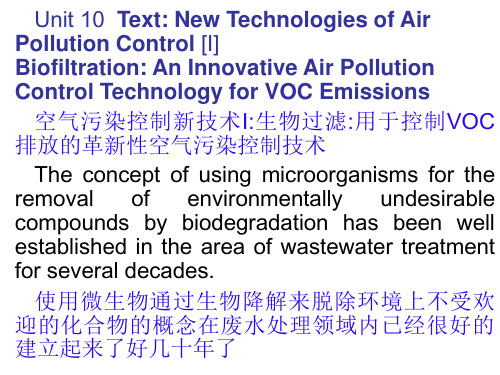
Finally, although several important papers on biofiltration have been published in English, most of the technical reports summarizing recent results were published in German.
使用微生物通过生物降解来脱除环境上不受欢 迎的化合物的概念在废水处理领域内已经很好的 建立起来了好几十年了
Not until recently, however, have biological technologies been seriously considered in the United States for the removal of pollutants from other environmental media.
特别是, 在美国的大多数州, 以一个全面的方式 控制从更小的污染源释放的空气毒物, VOC和臭 气的管理制度还没有建立起来.
Moreover, little financial support for investigating the applicability of biofiltration for these sources has been provided by government agencies.
The development of biofiltration in West
Germany, most of which took place in the late 1970s and the 1980s, was brought about (由… 引起的,带来的) by a combination of increasingly stringent regulatory requirements and financial
开启片剂完整性的窗户(中英文对照)
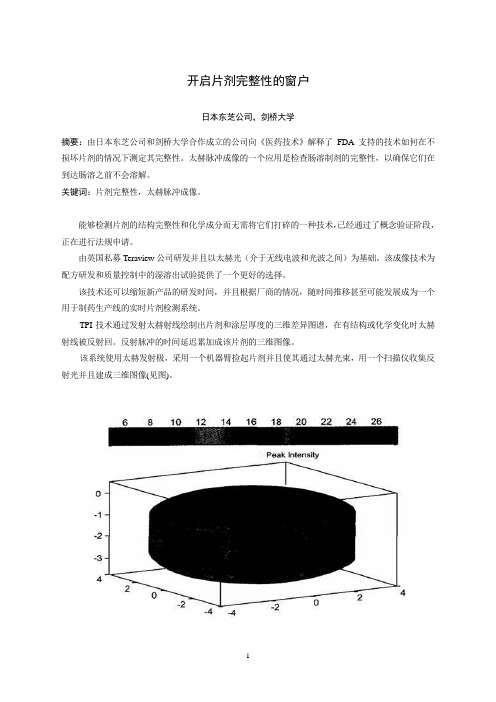
开启片剂完整性的窗户日本东芝公司,剑桥大学摘要:由日本东芝公司和剑桥大学合作成立的公司向《医药技术》解释了FDA支持的技术如何在不损坏片剂的情况下测定其完整性。
太赫脉冲成像的一个应用是检查肠溶制剂的完整性,以确保它们在到达肠溶之前不会溶解。
关键词:片剂完整性,太赫脉冲成像。
能够检测片剂的结构完整性和化学成分而无需将它们打碎的一种技术,已经通过了概念验证阶段,正在进行法规申请。
由英国私募Teraview公司研发并且以太赫光(介于无线电波和光波之间)为基础。
该成像技术为配方研发和质量控制中的湿溶出试验提供了一个更好的选择。
该技术还可以缩短新产品的研发时间,并且根据厂商的情况,随时间推移甚至可能发展成为一个用于制药生产线的实时片剂检测系统。
TPI技术通过发射太赫射线绘制出片剂和涂层厚度的三维差异图谱,在有结构或化学变化时太赫射线被反射回。
反射脉冲的时间延迟累加成该片剂的三维图像。
该系统使用太赫发射极,采用一个机器臂捡起片剂并且使其通过太赫光束,用一个扫描仪收集反射光并且建成三维图像(见图)。
技术研发太赫技术发源于二十世纪九十年代中期13本东芝公司位于英国的东芝欧洲研究中心,该中心与剑桥大学的物理学系有着密切的联系。
日本东芝公司当时正在研究新一代的半导体,研究的副产品是发现了这些半导体实际上是太赫光非常好的发射源和检测器。
二十世纪九十年代后期,日本东芝公司授权研究小组寻求该技术可能的应用,包括成像和化学传感光谱学,并与葛兰素史克和辉瑞以及其它公司建立了关系,以探讨其在制药业的应用。
虽然早期的结果表明该技术有前景,但日本东芝公司却不愿深入研究下去,原因是此应用与日本东芝公司在消费电子行业的任何业务兴趣都没有交叉。
这一决定的结果是研究中心的首席执行官DonArnone和剑桥桥大学物理学系的教授Michael Pepper先生于2001年成立了Teraview公司一作为研究中心的子公司。
TPI imaga 2000是第一个商品化太赫成像系统,该系统经优化用于成品片剂及其核心完整性和性能的无破坏检测。
ISPE HVAC(翻译版)国际制药工程协会对空调系统的基准指南
The Role of Chemistry in Biomedical Applications
The Role of Chemistry in BiomedicalApplications在生物医学应用中,化学起着重要的作用。
化学所提供的分析方法和工具,对于发现和设计新的药物、诊断研究和治疗都发挥着关键的作用。
在本文中,我们将深入探讨化学在生物医学应用中扮演的角色。
1. 药物发现和设计药物发现和设计是化学在生物医学应用中最广泛应用的领域之一。
药物发现和设计的主要目的是发现具有特定生物活性的化合物,如具有治疗作用的药物分子。
为了达到这个目的,化学家们使用各种技术,例如化学合成、计算机建模和高通量药物筛选等。
一种非常成功的药物筛选技术是高通量筛选(HTS)。
高通量筛选是一种通过大规模的药物库,在短时间内大规模筛选药物分子的方法。
化学家们使用无数的化合物对库进行筛选,以发现具有生物活性的化合物。
这个方法对于药物发现和设计有着巨大的帮助,因为它可以在很短的时间内测试数百万甚至上千万的化合物,快速地确定最有前途的候选分子。
2. 诊断和检测化学在生物诊断和检测中发挥着重要的作用。
化学家们利用这些方法开发出各种工具,如免疫分析和质谱分析等,以用于生物医学应用。
免疫分析是一种常见的检测方法,它利用抗体与特定生物分子结合的原理来检测特定生物分子的存在。
通过制备出与特定生物分子结合的抗体,化学家们能够将抗体与该生物分子结合,从而检测它们的存在。
这些检测方法对于临床实践和药物筛选都非常重要,可以用于检测感染病毒、血液中药物分子和非法药物等。
质谱分析是一种分析化学方法,可以提供对于分子结构的高分辨率探测。
质谱分析广泛应用于各种生物医学应用中,包括药物发现、药物代谢动力学、生物分子结构和鉴定以及重大疾病的诊断等领域。
由于质谱分析的分辨率非常高,因此它也可以用于检测分子之间微小的化学变化,如蛋白质化学修饰和突变等。
3. 生物医学成像生物医学成像是一种非常重要的诊断和治疗工具,可以用来识别和确定各种疾病状态。
化学可以很好地应用于生物医学成像,如利用MRI、PET和SPECT等技术。
反硝化生物技术在浓盐水脱氮改造中的实践
第43卷第 9 期2023年9月Vol.43 No.9Sep.,2023 工业水处理Industrial Water TreatmentDOI:10.19965/ki.iwt.2022-0948反硝化生物技术在浓盐水脱氮改造中的实践孙江虎,王努驰,李星焱,李丛益(中国石油四川石化有限责任公司公用工程部,四川成都 611930)[ 摘要]随着国家和地方环保标准的提高,某石化企业浓盐水处理系统采用“两级臭氧接触池+生物滤池+活性炭滤池”工艺处理后的污水仍不能满足总氮≤15 mg/L的排放标准。
因此,在现有处理工艺构筑物的基础上,采用反硝化生物滤池(DNBF)脱氮技术对其进行技术改造,构建出乙酸投加PID控制模型,通过调节DNBF系统C/N、进水TDS、进水温度、控制回流比,使DNBF系统出水硝态氮稳定在8 mg/L左右,经过4 a多的连续运行,外排水质满足国家、地方相关排放标准要求。
[关键词]脱氮;工艺改造;浓盐水;反硝化生物滤池[中图分类号]X703.1 [文献标识码]B [文章编号]1005-829X(2023)09-0213-06Application of denitrifying biotechnology indenitrification of concentrated brineSUN Jianghu,WANG Nuchi,LI Xingyan,LI Congyi(Utility Engineering Department,Petrochina Sichuan Petrochemical Company,Chengdu 611930,China)Abstract:With the improvement of national and local environmental protection standards,the wastewater treated by the combined process of two-stage ozone contact pool,biological filter and activated carbon filter in the concen⁃trated saline treatment system of a petrochemical enterprise cannot meet the requirements of the discharge standard of total nitrogen ≤15 mg/L. Therefore,on the basis of the existing treatment process structures,the enterprise ad⁃opted DNBF denitrification technology to carry out technical transformation,and constructed the PID control model of acetic acid injection. By adjusting the C/N ratio,inlet TDS,inlet temperature,and reflux ratio of DNBF system,the nitrate ammonia at the outlet of DNBF system was stable at about 8 mg/L. After more than four years continuous operation,the effluent water quality met the requirements of the relevant national and local discharge standards. Key words:removal of nitrogen;process transformation;concentrated brine;denitrifying biological filter在我国,水体富营养化导致地表水环境质量下降的问题日益严重,对地表水体的生态环境造成了严重影响〔1-2〕。
生物滤波器安装指南说明书

Positioning your Bio-FilterYour filter can be also used to provide water to your waterfall or stream.Ensure the bottom of the filter is above the level of the top of waterfall, since gravity causes the water to flow out and down.You may place the filter far away from the top of the pond or waterfall if you choose. This helps prevent the filter from ruining the appearance of your pond or waterfall. A good place is up on a hill so water can flow downhill into waterfall or pond. The filter can be hidden behind bushes and other plants or rocks.Hose Clamps: For best results secure all tubing connections with stainless steel hose clamps (found in plumbing department).Attaching Tubing to Discharge Outlet FittingSimply attach 1 ¼ in. ID flexible tubing to the discharge outlet fitting (bottom of filter) and use any length required. Never restrict the outflow by using a smaller diameter tube or attaching a UV clarifier to the discharge.Attaching Tubing from Pump to Inlet Fitting.Using either ½ in., ¾ in., or 1 in. tubing, connect pump (optional UV) and inlet fitting. TIP:Choose the largest diameter hose your pump allows for maximum flow.Recommended Pumps: TetraPond Water Garden Pump 325 GPH TetraPond Water Garden Pump 550 GPHThe Tetra Venturi and Trickle-Flow SystemThe water inlet into your filter is fitted with an advanced Venturi system, which draws air into the in-flowing water, creating the beneficial bacteria with the ideal conditions to decompose waste. This, when combined with the use of “Trickle Filtration” encourages the prolific growth of beneficial bacteria, which helps to keep the pond free of pollutants.Universal Inlet: If you find that the water flow from the pumpis too much for the Venturi inlet, or it clogs too easily, you may replace it with the universal inlet fitting for higher flows.Assembly of FilterHose Clamps: For best results, secure all tubing connections with stainless steel hoseclamps (found in plumbing department).hand tight.Do not use the stepped universal fitting for the bottom outlet.Typical Gravity Filter ApplicationBioFilter PF-1Can be positioned away from pond or waterfall to concealConnect ½ in., ¾ in., or 1 in.tubing to connect pump, UV and BioFilterUV Clarifier keeps water green freeWater Garden PumpConnect 1¼ in. ID tubing to filter dischargePre-Filter forWater Garden PumpDiagram 5TIP: Choose the largest diameter hose your pump will allow for maximum flow. Be sure you 4. D etermine the diameter hose that will run from the UV or pump into the filter (either ½ in., ¾ in. or 1 in. ID). Select the Venturi or universal inlet fitting. If you find the water flow from the pump is too much for the Venturi inlet, or it clogs too easily, you may replace it with the universal inlet fitting for higher flows. If using the universal fitting (instead of the Venturi), you may use ½ in., ¾ in. or 1 in.5. Secure the lid.ClearChoice ® BioFilter PF- 1Bio-Filter Parts list:A. Screw lidB. Filter bodyC. W ater inlet with Venturi system Fits ¾ inch & 1 in. ID tubingD. Water outlet (Fits 1 ¼ in. ID tubing)E. Biological filter media (plastic balls)F. Fine filter padG. Coarse filter padH. Overflow systemI. Spray bar systemJ. U niversal inlet(Fits ½ in., ¾ in., or 1 in. tubing)Instruction for use:The TetraPond PF-1 filter is suitable for ponds up to 1200 gallons with average stock fish.How the TetraPond BioFilter PF-1 works:Pond water is pumped into the filter. It passes through the foam, which sieves coarse suspended debris from the water (Mechanical Filtration).The water from stage 1 then passes through the finer foam, which provides further filtration.The final purification process of the water occurs on the surface of the biological filtration media. Beneficial bacteria will naturally colonize on this massive surface area and convert the harmfulpollutants in the water into relatively harmless nitrates, which are absorbed by the aquatic plants from partial water changes, thus removing about 25% of the pond water with fresh water.Filter outlet connectionBlack gasket (1)Red gasket (3)Maintenance and Care of the Bio-FilterCleaningDebris will collect on the foam pads. These should be checked and cleaned on a regular basis. Remove the filter pads and clean in a bucket of pond water. Do not use untreated tap water for cleaning, since it contains chlorine that can destroy the beneficial bacteria colonies in the foam and biological plastic media.The period between each cleaning is dependent on many factors such as the number of fish in the pond, algae growth, and the size of the pond. A rule of thumb is about every two weeks.Should debris and sludge accumulate at the bottom of casing, this media can be gently rinsed with pond water only. Do not use untreated tap water. It is not necessary or advisable to thoroughly clean the media since that may diminish the beneficial bacteria.Also, check the spray bar to ensure the holes are not clogged.Never use soap or detergents to clean any parts of the filter.Winter CareDuring the winter, the fish in the pond go through a period of rest where they become very inactive and waste production becomes very low. At this time, the filter should be turned off, cleaned, and stored indoors until the following spring. Never leave water in the casing when there is a chance of freezing temperatures.When starting the filter again in the spring, it will go the through the same maturation process as the first year. Be sure not to overfeed your fish in the early spring.Replacement PartsReplacement pad set available through your retailer ClearChoice Replacement filter pad item # 16785For other parts, please contact our specialists at Tetra Customer Care.“Maturation” of your filterA biological filter must undergo a period of “maturation” before it is fully efficient. During this period of time, beneficial bacteria grow and colonize on the biological filter media until the population is large enough to purify the waste in the water. The initial maturation of the filter takes approximately 4 to 6 weeks (after spring has arrived). To avoid dangerous levels of pollutants during this time, gradually introduce your pond fish and take great care not to overfeed them, especially before the filter has matured. Run the bio-filter 24 hours a day.123gasket©2009 Tetra Holding (US) Inc. • 3001 Commerce Street Blacksburg, VA 24060-6671Tetra® is a registered trademark • Consumer Support Service (800) 526-0650Questions? Problems? Missing Parts?B efore returning the product, please call our Customer Care department at 800-526-0650,Monday–Friday 7:30 a.m. to 5:30 p.m., Eastern USA Time.or email us at ***********************O ur Customer Care Department is here to provide assistance to help you solve your problem.!WARRANTY CARDThank you for purchasing TetraPond ClearChoice® BioFilter PF-1.Please fill out this card and mail it to the address below OR complete an e-registration form by logging on to to validate your warranty.Name of purchaser: ____________________________________________________Address: _____________________________________________________________City ________________________________ST _____Zip code: ________________E-mail Address: _______________________________________________________Date of purchase: _____________________________________________________TetraPond respects your rights for privacy. Any and all personal information collected here will be kept strictly confidential and will not be sold, reused, rented, or otherwise disclosed.Electronic NewsletterqYes, I would like to receive free e-mail updates on water gardening, including tips, new products, and or other helpful information.q No, I would not like to receive any e-mail updates at this time.!Please visit us at !16783-901 REV. A。
Filtralite生物过滤器操作与维护手册说明书
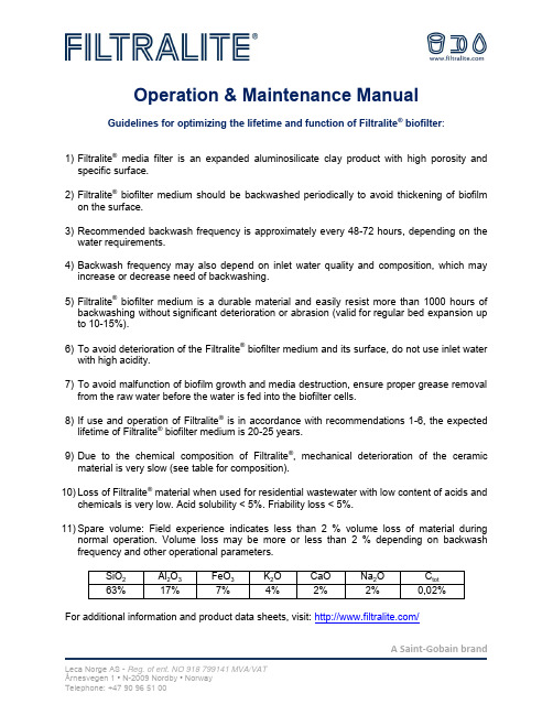
A Saint-Gobain brandOperation & Maintenance ManualGuidelines for optimizing the lifetime and function of Filtralite ® biofilter :1) Filtralite ® media filter is an expanded aluminosilicate clay product with high porosity and specific surface.2) Filtralite ® biofilter medium should be backwashed periodically to avoid thickening of biofilm on the surface.3) Recommended backwash frequency is approximately every 48-72 hours, depending on the water requirements.4) Backwash frequency may also depend on inlet water quality and composition, which may increase or decrease need of backwashing.5) Filtralite ® biofilter medium is a durable material and easily resist more than 1000 hours of backwashing without significant deterioration or abrasion (valid for regular bed expansion up to 10-15%).6) To avoid deterioration of the Filtralite ® biofilter medium and its surface, do not use inlet water with high acidity.7) To avoid malfunction of biofilm growth and media destruction, ensure proper grease removal from the raw water before the water is fed into the biofilter cells.8) If use and operation of Filtralite ® is in accordance with recommendations 1-6, the expected lifetime of Filtralite ® biofilter medium is 20-25 years.9) Due to the chemical composition of Filtralite ®, mechanical deterioration of the ceramic material is very slow (see table for composition).10) Loss of Filtralite ® material when used for residential wastewater with low content of acids andchemicals is very low. Acid solubility < 5%. Friability loss < 5%.11) Spare volume: Field experience indicates less than 2 % volume loss of material duringnormal operation. Volume loss may be more or less than 2 % depending on backwash frequency and other operational parameters.For additional information and product data sheets, visit: /Methodology for retention of Filtralite® in filters Consider two main factors to avoid loss of Filtralite® from filter beds:1. Filter design2. Backwash1. Filter designTo reduce the risk of loss of Filtralite® material from the filters, it is important that the filters are designed with a freeboard, i.e. the height from the top of the filter bed to the outlet for the dirty backwash water. The freeboard should be about 1.5 metre. A high freeboard area lowers the risk of loss of material.It is also important that the nozzles in the filter floor are completely levelled to ensure equally distributed air- and water-flow during backwash and equal air- and water-velocities across the whole filter.2. BackwashTo obtain good backwash and avoid loss of Filtralite®material from the filter, it is recommended to backwash with air and water together. Typical air velocity is about 35 m/h (based on a sufficient freeboard as described in section 1 above). For recommended water velocity and expansion requirements; see individual instructions for specific Filtralite®products. It is recommended to end backwashing cycles using only water for backwashing (usually at ~30 % expansion).For additional information and product data sheets, visit: /A Saint-Gobain brandFiltralite® Storage GuidelineThis is a guideline for the optimal performance and ease of handling of the filter material. All types of Filtralite® materials can be delivered in bulk. Bulk deliveries can be made to all parts of the world, either as road transport with trucks, or as sea- or river transport with vessels. Delivery in big bags can be done for all applications and all Filtralite® product qualities. The big bags can be transported on trucks, trains or vessels, or they can be stuffed into containers. Transport in containers is a good solution for smaller volumes and long sea transports.Storage of the materialFiltralite®should be stored in big bags (especially material for drinking water filtration), preferably indoors, or covered with a temporary roof/tarpaulin. The material should never be placed directly on the ground to avoid contamination. Big bags should be kept out of direct sunlight (the bags are degradable) and the storage period should not exceed 6 months.If properly handled, Filtralite®filter medium can in most cases be stored outdoors without decreasing product quality. If stored outdoors, it should be taken into consideration that water is adsorbed when exposed to rainfalls, which increases weight and transport expenses. During winter, any material stored outdoors can freeze into "blocks" that will take time to melt. Filtralite®P should never be stored outdoors, as rain will wash out parts of the material, which will lead to reduced efficiency of the media.Blowing of the materialBy using tank trucks with blowing equipment, the most Filtralite® materials can be pneumatically discharged directly into the filters. Filtralite® Nature, Filtralite® Pure NC 0,8-1,6 mm and Filtralite®NC 1,5-2,5 mm is not recommended to be pneumatically blown.Pre-soaking of the materialSome Filtralite® materials require a period of pre-soaking, especially the NC-quality materials. Leca recommends minimum 2-7 days soaking of such materials before use. Some qualities might require longer time periods of soaking before the material is fully saturated, depending on the water quality.For additional information and product data sheets, visit: /A Saint-Gobain brand。
- 1、下载文档前请自行甄别文档内容的完整性,平台不提供额外的编辑、内容补充、找答案等附加服务。
- 2、"仅部分预览"的文档,不可在线预览部分如存在完整性等问题,可反馈申请退款(可完整预览的文档不适用该条件!)。
- 3、如文档侵犯您的权益,请联系客服反馈,我们会尽快为您处理(人工客服工作时间:9:00-18:30)。
Energy Procedia 11 (2011) 3965 – 39691876-6102© 2011 Published by Elsevier Ltd. Selection and/or peer-review under responsibility of the Organizers of 2011 International Conference on Energy and Environmental Science.doi:10.1016/j.egypro.2011.10.786Available online at vailable online at EnergyProcediaEnergy Procedia 00 (2011) 000–000 /locate/procediaICEES 2011: 14–16 October 2011, SingaporeDesign and Application of Biofilter to Control Odor inWastewater Treatment PlantH Wang a,b ∗, H B Li aa Key Laboratory of Regional Environment and Eco-Remediation, Ministry of Education, Shenyang University, Shenyang, Chinab School of Resources and Civil Engineering, Northeast University, Shenyang, ChinaAbstractThe biofilter was introduced to control odor gas in wastewater treatment plant through the analysis to the characteristics of odor gas and the process of biological deodorization.The collection and transportation of odorous gas and the operations of the odor control systems were described in detail. The running practice indicated that the process has steady and reliable treatment effect, and the pollutants can meet the requirement of the secondary standard of discharge standard of pollutants for municipal wastewater treatment plant (GB 18918-2002) in China.© 2011 Published by Elsevier Ltd. Selection and/or peer-review under responsibility of ICEES 2011.Keywords :odor control : biofilter; wastewater treatment plant ;biological deodorization.1. IntroductionOdors and sludge are inevitably produced in the process of industrial wastewater treatment. And sludge treatment has been fully taken into account in the design and construction of the wastewater treatment plant. However, odors is often ignored because of invisible [1]. With the improvement of public awareness of environmental protection, odor problems have attracted more attention. Many developed countries have formulated relevant laws and regulations to control the odor gases strictly. In the design of wastewater treatment system, odor gas is also as an important component of treatment [2]. For example, chemical scrubbers were often used to remove H 2S and NH 3, and biofilter and biotricking filters for removing odor and volatile organic compounds (VOCs) [3]. Many application of technology and complete sets of equipment were researched and Used in the sewage treatment plant. In recent years, China has enhanced treatment and management of malodorous gases generated in the process of treating∗Corresponding author. Tel.: 0086-24-62266671; E-mail address : wh51@.© 2011 Published by Elsevier Ltd. Selection and/or peer-review under responsibility of the Organizers of 2011 International Conference on Energy and Environmental Science.3966H Wang and H B Li / Energy Procedia 11 (2011) 3965 – 3969 wastewater. Many pre-built wastewater treatment plants have all built up ozone treatment facilities [4].A refinery, which wastewater treatment plant is oil separation- flotation - biological treatment, and the sewage quantity is 900m3/h. The odors emitted by the facilities seriously pollute the surrounding environment and endanger people's health. The odors is high-volume, low concentration. So the treatment facilities must be constructed to solve the odors problems in the surrounding environment.2.Summary of ProjectIn the running process of wastewater treatment, the solubility of oil components and the filling contained in the wastewater were released additional agents stink. The odor mainly contains a lot of volatile organic compound, such as trimethylamine, methyl mercaptan, dimethyl sulfide, dimethyl disulfide, carbon disulfide, styrene, etc. In addition, the odor also contains a small amount of NH3, H2S and other inorganic components. After monitored by environment agency, odors concentration of each component changes, with the nature of instability, is high-volume, low concentration of odors, which is about 6000-10000 odor units.A total of six oil separating tank has a fibreglass cover closed. Oil separating tank which is 12m long,4.5m wide, 0.7m high from the liquid to the sealing cover, is made to be the total surface space of about 230m3. Considering ventilated twice per hour, the air volume is estimated 460 m3/h.There are 10 flotation tanks which are not closed and 21m long and 4.5m wide, the length of reaction zone is 16m. According to site conditions, it is arched glass steel cover closed with the height of 1.2m. The water-side is flat glass steel cover closed with the height of 0.7m from the flat surface to the seal. The total space above liquid level is about 1200m3. Considering people do not often enter it as well as ventilation twice per hour, the air volume is 2400 m3/h. The air volume of wastewater regulating tank is designed 5000m3/h. In summary, the system air volume is 8000 m3/h.The concentration of some compounds and odors emissions should meet the odor emission standard value provided in "GB14554-93 emission standards for odor pollutants", the concentration of ammonia, carbon disulfide, and styrene are 4.9 kg/h, 1.5 kg/h and 6.5 kg/h respectively. The odors concentration is 2000 odor units. The standard is made as the design height of 15m tailpipe.3.Process Selection and Principles3.1.Deodorization process selectionAmong of deodorization process them, biological deodorization method, which covers a small area with medium investment and a simple operation management, is used more often in wastewater treatment. Biological odor absorption method mainly includes biological scrubbers, bio-aeration tank absorption and biological filters [5], comparing their parameters as shown in Table 1.By comparison, biological filtration is used with few equipment, simple operation and low investment and operating costs. It can’t be plugged easily and have a wide range of applications without additional nutrients with little or only a small number of secondary pollution, so the option of a biological filtration as the primary process.3.2.Principles of biofiltration odorDeodorization process of biological filtration is a safe and reliable treatment with deodorization efficiency of more than 95%. The principle is that a certain humidity, VOCs are contacted with an immobilized culture of pollutant degrading organism in the biological filter, which full of activeH Wang and H B Li / Energy Procedia 11 (2011) 3965 – 39693967microorganisms and absorbing and degrading odors.Table 1. The comparison of biological deodorization methodParameters Methodsbiological scrubbersbio-aeration tank absorptionbiofilter additional nutrient yes no nocost of investment and operationhigh low lowsurface area of filler small, uneasy to bejammed / small uneasy to bejammed liquid phase and biological phase circulation ,suspended biologicalliquid phase both circulation ,site areasmall large small removal of VOCs highlow highapplication rangecannot treat slightly soluble compoundswidewide, highconcentration pollutantBiological deodorization process is mainly in three steps: the first, emission of organic pollutants in the first contact with water, and is diffused into the liquid film; the second, organic pollutants dissolved (or mixed) in the liquid membrane are further spread to the biofilm in the promotion of differential concentration; at last, organic pollutants into the microbial body in its own metabolism as energy and nutrients are decomposed and turned into harmless compounds [6-7]. 4. Design of biological deodorization 4.1. Odor collection and deliveryOilseparating tank is installed sealing lid and just set the collection in each pool outlet. There are 10 flotation tanks with the length of 21 meters and the width of 4.5 meters, in which reaction zone is 16 meters with arched steel glass cover (8mm) closed. The in-water area and the out-of-water area are sealed with 30mm thick glass plate and set the observation hole, conducive to the scene of operations. The income outlet set at the top of the wastewater regulating tank makes the odor collected.The combination of the wind induction equipment is installed on the pipeline. Besides the water tanks’ own breathing valve, the wind system uses stepless variable frequency motor, by adjusting the speed of it to adjust the size of the exhaust volume, and thus control the operating pressure of the water tank. The system can be automatically controlled by differential pressure transmitters combined with frequency converter and PLC controller. The odor collection of the wastewater adjusting tank uses a separate transmission pipeline. The flotation tank and the oilseparating tank use the same transmission pipe and the valves are set on the outlets of each pond to adjust the air flow and help facilitate maintenance.The collection windpipe can be made of fibreglass reinforced plastic and take the elevated site. The flow rate of the branch is designed to be 4~6m/s and the flow rate of the dry tube is 8~10m/s. The outlet is arranged near the surface of the water and the air inlet is arranged at the top of the closures. The arrangement of outlets is based on the collection space and the structure size, and the number of outlets should be sufficient, even arranged to ensure that the odor can be taken away. To control the operational pressure of the wastewater storage tank, water storage tanks should be fitted with self-breathing valve to balance the pressure in the tank.3968H Wang and H B Li / Energy Procedia 11 (2011) 3965 – 39694.2.Process of biological filtration poolTwo bio-filter processes were used and the process flow was shown in Fig. 1.Fig. 1.the process chart of biofliterThe first stage is the pre-treatment. To spray washing water on the gas can initially remove the water-soluble substances (such as the smell of ammonia and hydrogen sulphide and organic matter) in odor gas and can regulate the physical and chemical properties of emissions (such as temperature, pH, humidity) , to create conditions for the follow-up biological filter. After spraying and washing, the relative humidity of the emission can be up to more than 95%. This can ensure that the water in the filter layer meets the needs of micro-organisms. A pre-treatment device is set up and the intake capacity is 8000 m3/h. In order to ensure adequate gas phase and liquid phase mixture, the work of the pre-treatment device is designed as the counter flow. The unit includes circulating pump (400V, 4Kw), water level control system, sprinkler system, condensate drainage system and may observe by opening the inspection window.The second stage is the biofilter. Its length is 15m, the width is 8.5m.The height is 3.5m and the height of the cloth gas zone is 0.5m. The total area is 127.5 m2 and the filter layer capacity is 160 m3/ (m2⋅h). The body is in the structure of the inside corrosion and made of carbon steel. The filling supporting (fabric gas plate) is made of glass steel stent.The biofilter filler provides attachment surfaces and some nutrient for the microbial population, so it must be highly porous and have high water retention capabilities. We use FT-1 composite biological filler, which has a long life time, up to 5 to 6 years. Many kinds of microorganisms attached to the filler make large surface area for microbial growth, homogeneous porosity and rational nutrition (N, P, K and trace elements). Due to the filler’s own good water absorption and adsorption and its organic nutrients, when the biofilter stops running, microbes can use the organic ingredients to maintain life activities. When the filler is up to the end of the useful life, a partial replacement for the filler and re-vaccination are needed.4.3.Operating parametersSurface load- A reasonable surface load can’t only make less change in the filling pressure drop, but resist the impact of high odor concentration as well as control the investment cost. The engineering height of the filler is generally 1.00~1.25 m and the minimum height is 0.50 m. The surface load is generally 100~150m3/ (m2⋅h), up to 200m3/ (m2⋅h). Based on the actual experience and the odor characteristics, the engineering filler height and the surface load were designed as 1.25 m and 160m3/ (m2⋅h).℃Temperature Control - The operating temperature of the biofilter is 10~ 45 and the optimum temperature is 25~35. To keep the deodorizing device and the gathering pipeline within a certain ℃temperature can ensure that the heat of the device filter bed and microorganisms is not emitted out.H Wang and H B Li / Energy Procedia 11 (2011) 3965 – 39693969 Meanwhile, the collected exhaust gas temperature is higher to ensure that exhaust gas temperature is℃maintained at above 10 as well as the good growth of microorganisms.Humidity control - The use of biofilter designed with deodorant spray humidification unit area canspray and wash gas before it enters the biological oxidation zone. Using the cycle of high lift pumps andhigh-quality spray nozzles and setting time quantitative heating through PLC, the odor can be efficiently, adequately washed and humidificated. The relative humidity of the odor into the biological oxidationzone is up to 90% to 100 %, which fully meet the working needs of the biofilter.At present, the biolfilter of biological deodorization system has been operated for a year and have proven efficient and reliable. The odor almost can’t be smelled around the wastewater plant. By the numerous monitoring to the emissions of biofilter, it completely meets the pollutant emission standard.5.ConclusionAccording to the emission characteristics of oil refineries, biological deodorizing process is chosen. Highly efficient filters and pre-scrubbers are used in the odor pre-treatment, which effectively control and regulate the temperature and humidity, and other physical characteristics to provide the favourable conditions for stable operation of the biofilters. The better treatment effect fully meets the secondary emission standards in the plant community of the Municipal Wastewater Treatment Plant Pollutant Emission Standards in China. The operation process of biofilter is stable, simple and efficient. It also provides the reference for the wastewater treatment plant in the related refinery to increase waste gas treatment facilities.AcknowledgmentWe thank the National Natural Science Foundation of China (Grant 50908151) and the NationalMajor scientific and technological specialized project in the 11th Five-Year Plan of china(Grant 2008ZX-07208-008), for generous funding.References[1] Eunsung Kan and Marc A. Deshusses. Development of foamed foamed emulsion bioreactor for air pollution control. Biotechnology and Bioengineering 2003;84(2):240-244.[2] Alvaro Martinez, Snehasheela Rathibandla, Kim Jones, Jose Cabezas. Biofiltration of wastewater lift station emissions: evaluation of VOC removal in the presence of H2S. Clean Technologies and Environmental Policy 2008;10(1),:181-187.[3] Marie-Caroline Delhoménie and Michèle Heitz. Biofiltration of Air: A Review. Critical Reviews in Biotechnology 2005;25(1-2): 53-72.[4] Jiang Lanlan and Shen Xiaoli. Selection and design of odor removal systems for a wastewater treatment plant. Environmental Pollution and Control 2007; 29:781-784.[5] Wang Liyan, Wang Aijie, Ren Nanqi, Du DAzhong. Present status and trend of bio-treatment of volatile organic compound. Journal of Harbin Institute of Technology 2004;36:732-735. (in Chinese)[6] Reza Iranpour, Huub HJ Cox, Marc A Deshusses, Edward D Schroeder. Literature review of air pollution control biofiltersand biotrickling filter for odor and volatile organic compound removal. Environment Progress 2005;24(3):254-267.[7] Zillia M, Palazzia E, Sene L, Convretl A, Borghi MD. Toluene and styrene removal from air in biofilters. Process Biochemistry 2001; 37(5): 423-429.。