hypermesh学习笔记
个人学习hypermesh的笔记
1. 如何添加重力collector-loadcols-name(自己输入名字)-card image-grav-creat/edit,G中输入重力加速度(注意单位一般输入9800),N1,N2,N3,(0,-1,0)表示Y轴负方向。
在BCs中选择control cards,然后选择acceleration,然后根据需要选择。
另外,如果要添加重力,那么材料属性里RHO一定要填写,这是表示密度。
2.划网格产生的问题在sw中建好的模型导入到hypermesh里本来是没有自由边,可是在一个面上划完网格后就产生了自由边。
这个自由边是肯定会产生的。
因为这个时候仅仅是在一个面上划了网格,按照自由边的定义,在这个面的外围没有其他的面与之相连,所有会产生自由边。
这个自由边不能去掉,而且没办法去掉。
3.网格密度对拓扑优化结果有影响。
4.拓扑优化中常用质量分数作为约束,但是除非在优化设计要求中明确提出优化后质量减轻的百分比,否则优化前很难断定质量分数应该选取多大合适,因此可能需要指定几个不同的质量分数分别进行优化,然后再在结果中选取最优参数5.为模态分析设置频率分析方法的card 是EIGRL其中ND跟设置有几阶模态有关系。
V1,V2设置频率范围。
6.coupled mass matrix耦合质量矩阵7.设置载荷类型BCs->load types->constraint->DAREA(dynamic load scale factor)这里是设置动态载荷。
8.频率载荷表collector type->loadcols->....->card image->TABLED1例如:TABLED1_NUM=2,X(1)=0,Y(1)=1.0,X(2)=1000,Y(2)=1.这样就定义了频率范围为0~1000Hz,幅值为1的载荷9.创建随频率变化的动态载荷loadcols->..->card image->RLOAD2(frequency response dynamic load,form2)10.Card Image是你在创建一个新的组的时候,通过Card Image赋予这个组里面的单元一些属性.具体怎么用,跟你用的模板有关对于hm7.0版本,如果选ANSYS模板,创建component的时候,Card Image所指定的就是这个组的单元的单元类型.(8.0 改了,不能通过Card Image定义单元类型了.)。
hypermesh笔记原创
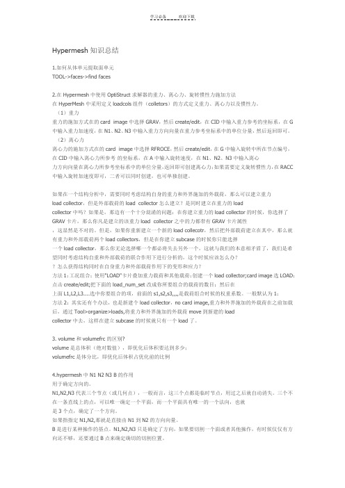
• F1 -- Hidden Line 隐藏线• F2 -- Delete 删除(删除任何对象都用此命令)• F3 -- Replace 合并两个节点• F4 -- Distance 测量距离角度等• F5 -- Mask 隐藏• F6 -- Element Edit 单元编辑(创建,合并,分割单元等)• F7 -- Align Node 节点共线排列• F8 -- Create Node 创建节点• F9 -- Line Edit 线编辑(非边界编辑)• F10 -- Check Elem 单元质量检查• F11 -- Quick Edit 快速几何编辑• F12 -- Automesh •自动网格划分 Shift+F1-F12, Ctrl+F1-F6Opening and Saving Files - HM-1010bumper_cen_mid1.hm1. Access the Import tab in one of the following ways:•From the Menu Bar, choose File, then Import•From the standard toolbar, click Import ()(这里的Import ()是在已有模型上加另一个模型)Importing and Repairing CAD - HM-2000Importing and Repairing CAD - HM-20002. Go to the autocleanup panel.查看拓扑情况,自动清理,可以删一些重复面,距离较小的自由边,修补结点问题Step 3: Delete the surface that overhangs the round corner.(删重复面) From the Geometry menu, point to Delete and click Surfaces或Press F2(和点叉一样)Step 4: Create surfaces to fill large gaps in the modelsurfaces panelkeep tangency(可以平滑过渡)Verify the auto create (free edges) check box is selectedStep 5: Set the global geometry cleanup tolerance to .01.(设置全局清理容差,这样其他地方的容差都是0.01)Press O to go to the options panelGo to the geometry sub-panelIn the cleanup tol = field, type 0.01 to stitch the surfaces with a gap less than 0.01.Step 8: Combine the remaining free edge pair using replace.Go to the replace sub-panel(quick edit是交换点,这里交换边,效果差不多)Step 9: Find and delete all duplicate surfaces.Access the Defeature panelSimplifying Geometry - HM-2020Step 4 (Optional): Review the quality of the mesh.Tool page, then select check elems(可以按要求检查,但不能编辑)3. In the length field, type 1.4. Click length to evaluate the minimum length.Many of the elements failing the length test are located around the fillets of this modelStep 6: Remove all surface fillets in the clip.1. Go to the defeature panel.In the min radius field, type 2.0.Refining Topology to Achieve a Quality Mesh-HM-2030Step 3: Review the mesh quality.4. In the length field, type 1.Step 6: Add edges to the surfaces to control the mesh pattern1. Access the surface editStep 7: Add edges to the surfaces to control the mesh pattern.Go to the trim with surfs/planes sub-panel2. In the with plane column, set the active selector to surfs.3. Select the surfaces indicated in the following image.4 If necessary, toggle the direction selector to N1, N2, and N3. ClickN1 to make the selector active.(这里选两个点,不要选第三个)6. Press F4 on the keyboard to enter the distance panel.7. Go to the three nodes sub-panel.(找到圆心)作为第四步的14. C lick trim.Step 9: Remesh the part.Step 10: Review the mesh quality.6. Access the automesh panel.7. Go to the QI optimize sub-panel.8. Verify that elem size = is set to 2.5 and the mesh type is set to mixed.9. Click edit criteria.10. I n the Target element size field, type 2.500.11. C lick Apply and OK.12. S elect surfs >> displayed to select all displayed surfaces.13. C lick mesh.Note that the old mesh is replaced by the new mesh.14. If there is a message saying, "There is a conflict between the user requested element size and quality criteria ideal element size," clickthe button, Recomute quality criteria using size of 2.5.15. A ccess the qualityindex panel by doing one of the following:• From the Menu Bar, select Mesh, then Check, then Elements, then Quality Index• From the main menu, select the 2D page, then select qualityindex16. G o to pg1 and verify that the comp. QI is 0.01.This low value indicates that the mesh is good quality. The higher the number, the lower the mesh quality.Creating and Editing Line Data - HM-2040Step 1: Create a component collector to geometryFrom the main menu, access the Geom page and click nodesGo to the type in sub-panel.Press f to fit the model to the model to the screenStep 3: Display the node IDs.Pick the Tool page and click numbers to access the Numbers panel Step 6: Create a line.select the Geom page, then select linesStep 7: Duplicate and translate lines.select the Tool page, then select translateStep 11: Duplicate and reflect an arc.select the Tool page then select reflectStep 12: Create two tangent lines.Go to the Lines panel, at tangents sub-panel.Step 16: Create a surface square on an X-Y plane.select the 2D page, then select planesGo to the square sub-panelSwitch from mesh, keep surf to surface onlyStep 17: Create a line that connects two parallel lines on an X-Y plane. Access the Lines panel.Go to the at intersection sub-panel.Use the lines with plane columnStep 19: Extend a line to a surface edgeGo to the Line Edit panel.Toggle from distance = to to:.Step 22: Remove all temp nodes.select the Geom page, then select temp nodesCreating Surfaces from Elements - HM-2050Step 2: Obtain surfaces from elements.1. From the Geom page, click surfaces, and select the from FE sub-panel. Step 3: Capture features with plot elements.1. From the surfaces panel, FE sub-panel, click the features button to access the features panel.This is a shortcut to this panel. You can also find features panel in the Tool page by selecting the features sub-panel.5. Select the advanced analysis check box.6. This option performs further analysis on the features created based on the angle and combines and extends them to create closed loops.3. From the features panel, select the edit sub-panel.9. Generate the surfaces using the surfaces panel, from FE sub-panel. (先生成单元曲面特征,然后修改曲面特征,然后再通过修改好的特征生成曲面,这样比直接不修改生成的好)Creating and Editing Solid Geometry - HM-2060Step 2: Create solid geometry from the bounding surfaces.From the Geom page, enter the solids panel.Step 3: Create a solid geometry cylinder using primitives.Go to the cylinder/cone sub-panel.Toggle full cone to full cylinder.Step 4: Subtract the cylinder’s volume from the rest of the part From the Geom page, go to solid edit2. Go to the boolean sub-panel.3. Verify that operation type: is set to simple (combine all).4. Set operation: to A-B (remove B from A).Step 5: Split the solid geometry using bounding lines.(如果不选择延伸,可以不闭合,但是必须确定一个平面,可以一次选择实体,多次切线)You should still be in the solid edit panel.1. Go to the trim with lines sub-panel.Step 6: Split the solid geometry using a cut line.(注意利用切换视图工具,是用中键确定)Step 7: Merge solids together.(合并之后不再有分割线)Step 8: Split the solid geometry with a user-defined plane.(只要三点确定一平面就行)4. Set the plane selector to N1, N2, N3.5. With N1 active, press and hold the left mouse button, and move the mouse cursor over one of the two edges shown in the following image.The edge should highlight.Step 9: Split the solid geometry with a swept line.(选择一个实体,选择扫掠线,选择轴,那扫掠线就沿着轴向切割实体)Step 10: Split the solid geometry with a principal plane.(z轴确定XY 平面,随便确定一基点就确定了平面的位置)3. Switch the plane selector from N1, N2, N3 to z-axis.Step 11: Split the solid geometry by creating surfaces inside the solids.(需要到surfaces先创建一个曲面,注意不要勾选自动,否则难选上线,再回到实体编辑选择刚创建的面)From the Geom page, go to surfacesGo to the spline/filler sub-panel.Deactivate auto create(free edge only) and keep tangency options Select the five lines shown in the following image:Step 12: Suppress extraneous edges on the part.(压缩冒出来的边) Enter the edge edit panel.Go to the (un)suppress sub-panel.Select lines >> by geoms.(因为之前创建编辑过的线有些可能冒出来了,所以要压缩)With the solids entity selector active, select the four solids shown in the following image.(创建实体的八种方法)Geometry and Mesh Editing Using the Quick Edit Panel - HM-2070select the 2D page, then select automeshVerify that the size and bias sub-panel is selected.Verify that elements to surf comp is selected.(注意选择的面板,网格大小设为0.1)Step 2: Simplify the geometry by removing unnecessary holes.1. From the main menu, select the Geom page, and click quick edit..2 For unsplit surf:, activate line(s).(不分割曲面面板,将不需要的孔去除,用填充的话会有共享边出现,而且网格质量不好)Step 3: Modify geometry around remaining small holesFor the split surf-line function, activate node.(分割小孔的时候,先把周围修好,再修内部)Step 4: Trim a washer layer into the surface around each of the four holes. In the offset value field next to washer split, enter 0.05.(偏移值越大,垫片越大)(调整密度,先调外部垫片再调内部,最后调周围)Step 5: Adjust the mesh around the large holes on the side surfaces. Use the split surf-line(可以用其他面板生成线辅助,然后再调整密度)这里可以不调,先修剪好,然后再退到auto mesh进行编辑,可以改类型,调的更好Step 7: Adjust the mesh on the mounting flange.split surf-line adjust density(对于那些交叉的调不了的网格,可以用faces edit中的untrim调试)交叉的也可以用quick edit中的split surf-nod 来调Creating 1-D Elements - HM-3000Step 2: Create 1-D bar elements.select the 1D page, then select barsGo to the bar2 sub-panel.3. Click ax = and enter the value 0.4. Click ay = and enter the value 0.5. Click az = and enter the value 0.These are the values for the bar offset.6. Click property = and select property1.A property is now assigned to the element.7. Click pins a = and enter the value 0.8. Click pins b = and enter the value 0.These are the values for the degrees of freedom9. Click the switch below update and select components from the pop-up menu.10. A fter x comp =, enter the value 1.11. A fter y comp =, enter the value 1.12. A fter z comp =, enter the value 1.The local y-axis is now specified.(这里x\y\z不能都为0)13. C lick node A and select the lower node in the graphics area.14. C lick node B and select the upper node in the graphics area. The two-noded bar element is created.Step 3: Create 1-D elements along a line.1. Go to the line mesh panel.2. Verify that the entity selector is set to lines..3. Select a line on the model.4. Verify that the segment is whole line option is set.5. Set element config: to rigid.6. Click mesh.The element density panel now appears.7. Click set segment to make it the active selector.8. In the elem density = field, enter 20.9. Click set all.10. C lick return twice to access the main menu.Step 4: Create 1-D elements from the feature in the model.Use the Model browser to turn off all of the geometry in the model. Tool page, then select features4. Click the Comps button and pick the feature_elements component.5. Click select to complete the selection.6. In the feature angle = field, enter 30.7. Select the ignore normals check box.8. Verify that create: is set to plot elements.9. Click features.The plot elements are created.Meshing without Surfaces - HM-3110Step 2: Create a concentric circle around a hole on the top face using the scale panel.(创建同心圆)Tool page and go to the scale panelClick uniform and enter 2.0 for the scale factor.(这个是放大的倍数)3. Press F4 to go to the distance panel.4. Go to the three nodes sub-panel.(选三点找到圆心)9. Switch the entity type to lines.10. I n the graphics area, select the circle.11. C lick lines >> duplicate >> original comp.12. C lick the origin: node selector to make it active.13. S elect the temporary node you created at the circle’s center.14. C lick scale +.A new circle is created, which is concentric with the originalStep 3: Create a radial mesh between each of the concentric circles using the spline panel.select the 2D page and go to the spline panel(然后再把其他的顶面创建,注意选三个外圆)shift+F2可以删除临时结点Step 5: Mesh the back face of the bracket using the line drag panel. select the 2D page and enter the line drag panel2. Go to the drag geoms sub-panel.3. Switch the drag: entity type from node list to line list.4. Select the line that is on the perimeter of the existing mesh and adjacent to the bracket’s back(选择一条拉伸的边)5. Click the along: line list selector to make it active.6. Select one of the two lines defining the back face and perpendicularto the selected line to drag.(选一条路径,即那条垂直的边)Step 6: Mesh the bottom face of the bracket using the ruled panel (如果想要删除重复图形的某一部分,可以先把不删除的隐藏起来)注意有时候平面创建了图形但是渲染方式不一样的话,可能看不到图形,这时需要切换渲染方式select the 2D page and enter the ruled panelClick node list and select by path.Switch the lower entity type to line list.(用结点路径选择拉伸的面,用线选择另一端Step 7: Mesh the rib using the skin panel.select the 2D page and enter the skin panelWith the line list selector active, select any two of the three lines defining the rib.(注意不要选三条)2-D Mesh in Curved - HM-3120Step 2: Set the mesh parameters and create the mesh.. In min elem size = field, type 15.000.(这里就是element size,如果设的太小会出错,比如说变黑)(或者进入edge deviation或surfaces deviation里面有min elem size设置,这里注意两个面板即使设置同样的数值,他们得出的形状和质量都不一样)5. Toggle to elems to surf comp.6. Select surfs > >by collector >> use size from the extended entity selection menu.Step 3: Set the chordal deviation parameters.2. Access the edge deviation sub-panel.3. Click min elem size = and type 1.000.Cycle through the parameter settings by pressing the TAB key after typing in a value.Step 4: Create the mesh.Step 5: Set the chordal deviation parameters and create the mesh.1. Set max angle = to 20.000.2. Select surfs >> by collector >> angle ctrl.3. Click select.4. Click mesh to create the mesh on the surfaces.Step 6: Set the chordal deviation parameters and create the mesh.1. Set max elem size = to 30.000.2. Select surfs >> by collector >> max size ctrl.3. Click select.4. Click mesh to create the mesh.(设置最大的单元越大则生成的网格单元越少,设置最小的单元越大,有可能使生成的网格越少,不是一定变少)QI Mesh Creation - HM-3130Step 2: Working with node and element quality optimization.Within the qualityindex panel, there are functions that allow the user to select individual nodes or elements, and then alter the position or shape of the node/element to optimize the element quality for the surrounding elements. The element qualities are optimized according to the settings in the qualityindex panel. These features are very useful for improving element qualities in local areas of the mesh.(在qualityindex面板,有让用户选择不同节点或元素的功能,然后改变元素节点的位置或形状/优化周围元素质量。
hypermesh学习笔记
Hypermesh学习笔记1一些常用的快捷键F2删除F3合并节点F4测量F5隐藏F6网格编辑F7节点对齐F8节点创建F11快速几何清理F12网格划分Shift+F2 临时节点创建与编辑Shift+F3 边界查找与缝合Shift+F10 单元法向量Shift+F4 对象平移translateShift+F7 投影ProjectShift+F11对象管理organizeCtrl+F1 (=Ctrl+F2)去背景截图2.方向向量的两种确定方法①2个点确定一个方向向量:该向量从N1指向N2②3个点确定一个方向向量:首先三个点确定一个平面,该方向向量为平面的法向,正方向由右手定则确定3.hypermesh 为不同的求解器建有限元模型的步骤:①首先user profile中选择对应的求解器②建模③模型导出成求解器可以识别的格式:file—export—solver data,并在export option中选择需要导出的对象一些实用的小技巧①平移技巧Translate的作用是平移,如果是复制平移,则在平移之前要先duplicate,duplicate时,会弹出副本归属对话框,这时可以将需要副本归属的集合设置成当前,然后在副本归属对话框中选current comp,这样复制平移的对象就会放到这个集合中,可以免去organize的步骤;②镜像技巧Reflect的作用是镜像,镜像的技巧参考平移技巧!特别说明:镜像时不一定非得严格找到对称平面,可以是与对称平面平行的平面,在用translate工具平移即可!③抽中面的技巧Midsurface的作用是抽取中面,抽中面时可以用sort选项将各个部件的中面分配到不同的component中,否则就会在一个component中。
④对象的保存和再提取Save fail 命令可以保存失败的单元,然后在所有含有elem选择器的界面中可以通过retrieve 命令将其提取出来!⑤surf 与elem的灵活运用由于surf面板中没有“通过硬点或节点创建面”命令,但是有“From FE”(即由网格创建面),所以可以先通过4个节点创建一个四边形单元,然后再通过“from FE”间接创建面。
Hypermesh总结-入门基础篇
Hypermesh总结-入门基础篇1、如何将.igs文件或.stl文件导入hypermesh进行分网?files\import\切换选项至iges格式,然后点击import...按钮去寻找你的iges文件吧。
划分网格前别忘了清理几何2、导入的为一整体,如何分成不同的comps?两物体相交,交线如何做?怎样从面的轮廓产生线(line)?都用surface edit。
Surface edit的详细用法见HELP,点索引,输入surface edit 3、老大,有没有划分3D实体的详细例子?打开hm,屏幕右下角help,帮助目录下hyperworks/tutorials/hyermesh tutorials/3D element,有4个例子。
4、如何在hypermesh里建实体?hm的几何建模能力不太强,而且其中没有体的概念,但它的曲面功能很强的.在2d面板中可以通过许多方式构建面或者曲面,在3D面板中也可以建造标准的3D曲面,但是对于曲面间的操作,由于没有"体"的概念,布尔运算就少了,分割面作就可以了5、请问怎么在hypermesh中将两个相交平面到圆角啊?defeature/surf fillets6、使用reflect命令的话,得到了映射的另一半,原先的却不见了,怎么办呢?法1、在选择reflect后选择duplicate复制一个就可以法2、先把已建单元organize〉copy到一个辅助collector中,再对它进行reflect,将得到的新单元organize〉move到原collector中,最后将两部分equivalence,就ok拉。
7、请问在hypermesh中如何划分装配体?比如铸造中的沙型和铸件以及冷铁,他们为不同材质,要求界面单元共用,但必须能分别开?你可以先划分其中一个部件,在装配面上的单元进行投影拷贝到被装配面上8、我现在有这样一个问题,曲线是一条线,我想把它分成四段,这样可以对每一段指定density,网格质量会比直接用一条封闭的线好。
hypermesh学习笔记共52页
Shot cut第 1 页一hypermesh网格划分⑴单元体的划分1.1梁单元该怎么划分?Replace可以进行单元结点合并,对于一些无法抽取中面的几何体,可以采用surface offset 得到近似的中面线条抽中线:Geom中的lines下选择offset,依次点lines点要选线段,依次选中两条线,然后Creat.建立梁单元:1进入hypermesh-1D-HyperBeam,选择standard seaction。
在standard section library 下选HYPER BEAM在standard section type下选择solid circle(或者选择其它你需要的梁截面)。
然后create。
在弹出的界面上,选择你要修改的参数,然后关掉并保存。
然后return.2 新建property,然后create(或者选择要更新的prop),名称为beam,在card image 中选择PBAR,然后选择material,然后create.再return.3 将你需要划分的component设为Make Current,在1D-line mesh,选择要mesh的lines,选择element size,选择为segment is whole line,在element config:中选择bar2,property 选择beam(上步所建的property).然后选择mesh。
现在可以欣赏你的beam单元了,用类似方法可以建立其他梁单元,据说bar单元可以承受轴向,弯曲的力,rod的只能承受拉压的力,beam可以承受各方向的力。
1.2 2D面单元的划分:利用2D- automesh划分网格(快捷键F12),所有2D都可以用这个进行划分网格。
(目前我只会用size and bias panel)1.3 3D四面体的划分:利用3D-tetramesh划分四面体网格,一般做普通的网格划分这个就够用了。
hypermesh入门篇(转)心得
hypermesh入门篇(转)其实各种CAE前处理的一个共同之处就是通过拆分把一个复杂体拆成简单体。
这个思路一定要记住,不要上来就想在原结构上分网,初学者往往是这个问题。
刚开始学,day1,day2,advanced training 和HELP先做一遍吧。
另外用熟24个快捷键。
做一下HELP里面的教程,多了解一些基本的概念和操作。
这样会快点入门。
论坛更多的是方法。
划分的方法要灵活使用,再有就是耐心。
1、如何将.igs文件或.stl文件导入hypermesh进行分网?files\import\切换选项至iges格式,然后点击import...按钮去寻找你的iges文件吧。
划分网格前别忘了清理几何2、导入的为一整体,如何分成不同的comps?两物体相交,交线如何做?怎样从面的轮廓产生线(line)?都用surface editSurface edit的详细用法见HELP,点索引,输入surface edit3、老大,有没有划分3D实体的详细例子?打开hm,屏幕右下角help,帮助目录下hyperworks/tutorials/hyermesh tutorials/3D element,有4个例子。
4、如何在hypermesh里建实体?hm的几何建模能力不太强,而且其中没有体的概念,但它的曲面功能很强的.在2d面板中可以通过许多方式构建面或者曲面,在3D面板中也可以建造标准的3D曲面,但是对于曲面间的操作,由于没有"体"的概念,布尔运算就少了,分割面作就可以了5、请问怎么在hypermesh中将两个相交平面到圆角啊?defeature/surf fillets6、使用reflect命令的话,得到了映射的另一半,原先的却不见了,怎么办呢?法1、在选择reflect后选择duplicate复制一个就可以法2、先把已建单元organize〉copy到一个辅助collector中,再对它进行reflect,将得到的新单元organize〉move到原collector中,最后将两部分equivalence,就ok拉。
hypermesh学习笔记
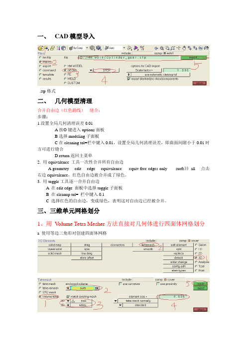
一、CAD模型导入.stp格式二、几何模型清理合并自由边(红色的线)---缝合:步骤:1.设置全局几何清理误差0.01A按O键进入options面板B选择modeling子面板C在cleaning tol=栏中键入0.01,设置全局几何清理误差,即曲面间隙小于0.01时方可进行缝合D return返回主菜单2. 用equivalence 工具一次性合并所有自由边A geometry----edit----edge----equivalence-----equiv free edges only------surfs》》all----点击右边equivalence,红色自由边被合并成了绿色。
3. 用toggle工具逐一合并自由边A 在edit edge 面板中选择toggle子面板B 在cleanup tol= 栏中键入0.1C 选择红色的自由边,变成绿色,表明这对自由边已经被合并。
三、三维单元网格划分1、用V olume Tetra Mesher方法直接对几何体进行四面体网格划分a 使用等边三角形对创建四面体网格注释:第二步在图中选择一个面b 使用直角三角形创建四面体网格c 沿曲面创建含有更多单元的四面体(在曲率比较大的地方网格比较细)d 在小特征区域创建具有更多单元的四面体网格2、用Standard Tetra Mesher方法直接对几何体进行四面体网格划分a 用S tandard Tetra Mesher划分四面体网格的前期准备(有面网格)由2D画好面网格。
b 进行三维体网格划分3、六面体和五面体网格划分的一般方法a.将正方形偏移拉伸,完成体的六面体网格划分注释:3选择要画正方形的表面注释:12选择刚才建立的平面网格b、用旋转的方式使面网格拉成体网格建立旋转的中心点按F4,进入distance面板注释:2选择三个点,用以确定创建的旋转中心将建立的面网格,以某一中心进行旋转,形成体网格。
注释:4选择要进行旋转的面网格6 选择刚才建立的旋转中心c、把体的两头的面网格建好,再通过从一个面到另一个面得扫描,完成体网格的建立建立面网格将两个面对好,进行扫面注释:3.4分别选择体两边已经建好的面网格5.6选择一对对应的单元上的三个点3、用Solid Map技术创建六面体网格Solid Map面板通过拉伸已经存在的2D有限元网格,并将这个被拉伸的2D有限元网格映射到一个由几何元素定义的实体中,从而形成一个三维体积来创建实体网格。
Hypermesh知识总结
Hypermesh知识总结1.如何从体单元提取面单元TOOL->faces->find faces2.在Hypermesh中使用OptiStruct求解器的重力、离心力、旋转惯性力施加方法在HyperMesh中采用定义loadcols组件(colletors)的方式定义重力、离心力以及惯性力。
(1)重力重力的施加方式在的card image中选择GRAV,然后create/edit,在CID中输入重力参考的坐标系,在G 中输入重力加速度,在N1、N2、N3中输入重力方向向量在重力参考坐标系中的单位分量,然后返回即可。
(2)离心力离心力的施加方式在的card image中选择RFROCE,然后create/edit,在G中输入旋转中所在节点编号,在CID中输入离心力所参考的坐标系,在A中输入旋转速度,在N1、N2、N3中输入离心力方向向量在离心力所参考坐标系中的单位分量,返回即可创建离心力;如果需要定义旋转惯性力,在RACC 中输入旋转加速度即可,二者可以同时创建,也可单独创建。
如果在一个结构分析中,需要同时考虑结构自身的重力和外界施加的外载荷,那么可以建立重力load collector,但是外部载荷的load collector怎么建立?是同时建立在重力的loadcollector中吗?如果是,那边有一个十分混淆的问题:在你建立重力的load collector的时候,你选择了GRAV卡片,那么你凡是建立的该重力load collector之中的力都带有GRAV卡片属性,这显然是不对的。
但是,如果你重新建立一个新的load collecotr,然后把外部载荷建立在其中,那么就有重力和外部载荷两个load collectors,但是在你建立subcase的时候你只能选择一个load collector,那么你无论选择哪一个都必将失去另外一个,这就与我们的本意相矛盾了,我们是希望同时考虑结构自重和外部载荷的联合作用下进行分析的,这个时候应该怎么办?怎么获得结构同时在自身重力和外部载荷作用下的变形和应力方法1:工况组合;使用"LOAD"卡片叠加重力载荷和其他载荷;创建一个load collector;card image选LOAD;点击create/edit;把下面的load_num_set改成你所要组合的载荷的数目;然后在上面L1,L2,L3....选中你要组合的项,前面的s1,s2,s3,,,,是载荷组合时候的权重系数。
Hypermesh知识总结

Hypermesh知识总结Hypermesh知识总结1.如何从体单元提取面单元TOOL->faces->find faces2.在Hypermesh中使用OptiStruct求解器的重力、离心力、旋转惯性力施加方法在HyperMesh中采用定义loadcols组件(colletors)的方式定义重力、离心力以及惯性力。
(1)重力重力的施加方式在的card image中选择GRAV,然后create/edit,在CID中输入重力参考的坐标系,在G 中输入重力加速度,在N1、N2、N3中输入重力方向向量在重力参考坐标系中的单位分量,然后返回即可。
(2)离心力离心力的施加方式在的card image中选择RFROCE,然后create/edit,在G中输入旋转中所在节点编号,在CID中输入离心力所参考的坐标系,在A中输入旋转速度,在N1、N2、N3中输入离心力方向向量在离心力所参考坐标系中的单位分量,返回即可创建离心力;如果需要定义旋转惯性力,在RACC 中输入旋转加速度即可,二者可以同时创建,也可单独创建。
如果在一个结构分析中,需要同时考虑结构自身的重力和外界施加的外载荷,那么可以建立重力load collector,但是外部载荷的load collector怎么建立?是同时建立在重力的loadcollector中吗?如果是,那边有一个十分混淆的问题:在你建立重力的load collector的时候,你选择了GRAV卡片,那么你凡是建立的该重力load collector之中的力都带有GRAV卡片属性,这显然是不对的。
但是,如果你重新建立一个新的load collecotr,然后把外部载荷建立在其中,那么就有重力和外部载荷两个load collectors,但是在你建立subcase的时候你只能选择一个load collector,那么你无论选择哪一个都必将失去另外一个,这就与我们的本意相矛盾了,我们是希望同时考虑结构自重和外部载荷的联合作用下进行分析的,这个时候应该怎么办?怎么获得结构同时在自身重力和外部载荷作用下的变形和应力方法1:工况组合;使用"LOAD"卡片叠加重力载荷和其他载荷;创建一个load collector;card image选LOAD;点击create/edit;把下面的load_num_set改成你所要组合的载荷的数目;然后在上面L1,L2,L3....选中你要组合的项,前面的s1,s2,s3,,,,是载荷组合时候的权重系数。
Hypermesh的一些总结

Hypermesh总结—入门一1、如何将.igs文件或.stl文件导入hypermesh进行分网?files\import\切换选项至iges格式,然后点击import...按钮去寻找你的iges文件吧。
划分网格前别忘了清理几何2、导入的为一整体,如何分成不同的comps?两物体相交,交线如何做?怎样从面的轮廓产生线(line)?都用surface editSurface edit的详细用法见HELP,点索引,输入surface edit3、老大,有没有划分3D实体的详细例子?打开hm,屏幕右下角help,帮助目录下hyperworks/tutorials/hyermesh tutorials/3D element,有4个例子。
4、如何在hypermesh里建实体?hm的几何建模能力不太强,而且其中没有体的概念,但它的曲面功能很强的.在2d面板中可以通过许多方式构建面或者曲面,在3D面板中也可以建造标准的3D曲面,但是对于曲面间的操作,由于没有"体"的概念,布尔运算就少了,分割面作就可以了5、请问怎么在hypermesh中将两个相交平面到圆角啊?defeature/surf fillets6、使用reflect命令的话,得到了映射的另一半,原先的却不见了,怎么办呢?法1、在选择reflect后选择duplicate复制一个就可以法2、先把已建单元organize〉copy到一个辅助collector中,再对它进行reflect,将得到的新单元organize〉move到原collector中,最后将两部分equivalence,就ok拉。
7、请问在hypermesh中如何划分装配体?比如铸造中的沙型和铸件以及冷铁,他们为不同材质,要求界面单元共用,但必须能分别开?你可以先划分其中一个部件,在装配面上的单元进行投影拷贝到被装配面上8、我现在有这样一个问题,曲线是一条线,我想把它分成四段,这样可以对每一段指定density,网格质量会比直接用一条封闭的线好。
hypermesh学习笔记
Shot cut一 hypermesh 网格划分 ⑴单元体的划分1.1 梁单元该怎么划分?Replace 可以进行单元结点合并,对于一些无法抽取中面的几何体,可以采用surface offset 得到近似的中面 线条抽中线:Geom 中的lines 下选择offset,依次点lines 点要选线段,依次选中两条线,然后Creat. 建立梁单元:1进入hypermesh-1D-HyperBeam ,选择standard seaction 。
在standard section library 下选HYPER BEAM 在standard section type 下选择solid circle(或者选择其它你需要的梁截面)。
然后create 。
在弹出的界面上,选择你要修改的参数,然后关掉并保存。
然后return.2 新建property,然后create (或者选择要更新的prop ),名称为beam,在card image 中选择PBAR,然后选择material ,然后create.再return.3 将你需要划分的component 设为Make Current,在1D-line mesh ,选择要mesh 的lines,选择element size,选择为segment is whole line,在element config:中选择bar2,property 选择beam(上步所建的property).然后选择mesh 。
现在可以欣赏你的beam 单元了,用类似方法可以建立其他梁单元,据说bar 单元可以承受轴向,弯曲的力,rod 的只能承受拉压的力,beam 可以承受各方向的力。
1.2 2D面单元的划分:利用2D- automesh 划分网格(快捷键F12),所有2D 都可以用这个进行划分网格。
(目前我只会用size and bias panel ) 1.3 3D四面体的划分:利用3D-tetramesh 划分四面体网格,一般做普通的网格划分这个就够用了。
HyperMesh--学习笔记—Teelon
目录☆选择边线上的点 (1)☆定义方向 (1)☆Organize管理集合器 (1)☆删除面、实体、网格等 (1)☆删除空部件 (1)☆删除重复的面 (2)☆压缩点 (2)☆压缩边界 (2)☆删除小孔 (2)☆删除面圆角 (2)☆删除倒圆角 (2)☆由封闭边线创建面 (3)☆在圆心处创建节点 (3)☆设置全局清理精度 (3)☆equivalence缝合曲面 (3)☆toggle合并相邻的自由边 (4)☆替换边 (4)☆替换点 (4)☆提取中性面 (4)☆用垂直于边界的线分割面 (4)☆unsplit surf补面 (5)☆处理圆孔周围的网格 (5)☆调整网格密度 (6)☆自动划分网格 (6)☆spline划网格 (7)☆skin划网格 (7)☆line drag延伸网格 (8)☆ruled扩展网格 (8)☆shrink wrap (8)☆降低comp.Q1值 (9)☆由封闭的曲面创建实体 (9)☆创建圆柱体 (9)☆用节点分割实体 (10)☆用线分割实体 (10)☆用面分割实体 (10)☆实体的布尔运算 (10)☆volume tetra四面体网格 (11)☆tetra mesh由2D封闭网格生成3D网格 (12)☆tetra remesh优化 (12)☆elems offset拉伸网格 (13)☆spin旋转网格 (13)☆faces在3D网格表面上提取2D网格 (14)☆linear solid在两个2D网格之间生成线性的3D网格 (14)☆沿边线扫掠网格 (14)☆剖切视图 (15)☆缝合网格中相近的节点 (15)☆one volume生成3D网格 (16)☆Mappable视图 (17)☆multi solids多个实体同时生成3D网格 (18)☆smooth调节网格 (18)☆拆分网格 (18)☆合并网格 (19)☆动态移动节点 (19)☆显示网格的法向量 (19)☆检查模型 (20)☆penetration检查穿透 (20)☆检查网格质量 (21)☆选择边线上的点选择时,按下鼠标左键不放,光标移动到边线上变成后松开,所选的边线变成白色,即可在该边线上选择点。
2019年hypermesh笔记
1 如何添加重力collector-loadcols-name(自己输入名字)-card image-grav-creat/edit,G中输入重力加速度(注意单位一般输入9800),N1,N2,N3,(0,-1,0)表示Y轴负方向。
在BCs中选择control cards,然后选择acceleration,然后根据需要选择。
另外,如果要添加重力,那么材料属性里RHO一定要填写,这是表示密度。
2.划网格产生的问题在sw中建好的模型导入到hypermesh里本来是没有自由边,可是在一个面上划完网格后就产生了自由边。
这个自由边是肯定会产生的。
因为这个时候仅仅是在一个面上划了网格,按照自由边的定义,在这个面的外围没有其他的面与之相连,所有会产生自由边。
这个自由边不能去掉,而且没办法去掉。
3.网格密度对拓扑优化结果有影响。
4.拓扑优化中常用质量分数作为约束,但是除非在优化设计要求中明确提出优化后质量减轻的百分比,否则优化前很难断定质量分数应该选取多大合适,因此可能需要指定几个不同的质量分数分别进行优化,然后再在结果中选取最优参数!5.为模态分析设置频率分析方法的card 是EIGRL:其中ND跟设置有几阶模态有关系。
V1,V2设置频率范围。
mass matrix耦合质量矩阵7.设置载荷类型BCs->load types->constraint->DAREA(dynamic load scale factor)这里是设置动态载荷。
8.频率载荷表collector type->loadcols->....->card image->TABLED1例如:TABLED1_NUM=2,X(1)=0,Y(1)=,X(2)=1000,Y(2)=1.这样就定义了频率范围为0~1000Hz,幅值为1的载荷9.创建随频率变化的动态载荷loadcols->..->card image->RLOAD2(frequency response dynamic load,form2)Image是你在创建一个新的组的时候,通过Card Image赋予这个组里面的单元一些属性.具体怎么用,跟你用的模板有关对于版本,如果选ANSYS模板,创建component的时候,Card Image所指定的就是这个组的单元的单元类型. 改了,不能通过Card Image定义单元类型了.)。
hypermesh入门总结(亲力亲为)

Hypermesh的初学步骤:1:几何清理:在导入模型后,会出现一些圆角,倒角,去除模型的通孔,螺纹孔,螺纹孔结构,对凸台进行简化处理;去除零件的筋板结构,将筋板填充为实体,从而将几何模型的外部形状规则化.2:模型切割:模型切割的目的是为了划分优化区域和非优化区域(常见的非优化区域有固定丝杠螺母的结构,固定滑块的结构,导轨部分以及其他主要承受载荷和约束的部分)为以后的优化做好基础。
切割后基础要进行布尔运算。
以DL25床身为例看一下模型切割,其实下面是凸台镶嵌到凹槽的一部分,没必要进行切割,凸台完全叶可以当成优化区域来作用。
那这个固定丝杠螺母的部分为什么没有切割呢?3:划分网格这是最为重要的一步,占据整个优化拓扑工作量的80%,目前只会简单的两种划分网格的方式:①3D-solid map-multi-solid 这是划分六面体等的主要划分方式②3D-tetramesh-volume solid 这是划分四面体的重要方式。
在划分是要充分注意到划分体的尺寸,看能不能符合自己所设定的划分网格所要的大小。
4:网格属性定义:定义material,property,component。
①材料material 时要在card image options的下拉列表中card image总要选择mat1 ,这种选择模式是必须要在optistruct中定义才可以,如果刚开始打开hypermesh中没有选择这个,可以在菜单栏中preferences-user profiles中重新定义。
Creat material后在左边的模型树种会弹出material,选择定义的材料如steel点击右键,选择card edit 进行定义E-弹性模量,G-杨氏模量(这个不是重力,要注意),nu-泊松比,RHO-密度。
一般都定义这四个,在定义它们时,要注意要定义那个选个后弹出的空白区域的值和你所要做的值一样也要在空白处点击一下,否则视为没有定义如下图所示:这代表定义了!此外,这几个单位和ansys中的单位统一划分方式也是一样的,有MPa,s,t吨,mm 这四个单位。
HyperMesh10.0学习笔记—Teelon
目录☆选择边线上的点 (1)☆定义方向 (1)☆Organize 管理集合器 (1)☆删除面、实体、网格等 (1)☆删除空部件 (1)☆删除重复的面 (2)☆压缩点 (2)☆压缩边界 (2)☆删除小孔 (2)☆删除面圆角 (2)☆删除倒圆角 (2)☆由封闭边线创建面 (3)☆在圆心处创建节点 (3)☆设置全局清理精度 (3)☆equivalence 缝合曲面 (3)☆toggle 合并相邻的自由边 (4)☆替换边 (4)☆替换点 (4)☆提取中性面 (4)☆用垂直于边界的线分割面 (4)☆unsplit surf 补面 (5)☆处理圆孔周围的网格 (5)☆调整网格密度 (6)☆自动划分网格 (6)☆spline 划网格 (7)☆skin 划网格 (7)☆line drag 延伸网格 (8)☆ruled 扩展网格 (8)☆shrink wrap (8)☆降低comp.Q1 值 (9)☆由封闭的曲面创建实体 (9)☆创建圆柱体 (9)☆用节点分割实体 (10)☆用线分割实体 (10)☆用面分割实体 (10)☆实体的布尔运算 (10)☆volume tetra 四面体网格 (11)☆tetra mesh 由2D 封闭网格生成3D 网格 (12)☆tetra remesh 优化 (12)☆elems offset 拉伸网格 (13)☆spin 旋转网格 (13)☆faces 在3D 网格表面上提取2D 网格 (14)☆linear solid 在两个2D 网格之间生成线性的3D 网格 (14)☆沿边线扫掠网格 (14)☆剖切视图 (15)☆缝合网格中相近的节点 (15)☆one volume 生成3D 网格 (16)☆Mappable 视图 (17)☆multi solids 多个实体同时生成3D 网格 (18)☆smooth 调节网格 (18)☆拆分网格 (18)☆合并网格 (19)☆动态移动节点 (19)☆显示网格的法向量 (19)☆检查模型 (20)☆penetration 检查穿透 (20)☆检查网格质量 (21)☆选择边线上的点选择时,按下鼠标左键不放,光标移动到边线上变成后松开,所选的边线变成白色,即可在该边线上选择点。
hypermesh 笔记

任何节约归根到底是时间的节约——马克思Hypermesh 10.0 学习笔记hewaixingyun@目录目录 (2)一Hypermesh 10.0 操作界面介绍 (4)1 Hypermesh软件的构成 (4)2 Hypermesh中快捷键的设置 (5)3实例1.1 (6)二几何简化处理及线、面、体的操作 (7)1方向的确定方法 (7)2节点(nodes)和硬点(point) (7)3线、面、体的产生 (8)4移动几何 ................................................................................................................... 错误!未定义书签。
5几何体的简化意义 (8)6实例 ........................................................................................................................... 错误!未定义书签。
三0D与1D单元的介绍. (9)1. 单元的介绍 (9)2. beam单元的创建 (9)3. spring单元的创建 (9)4. mass单元的建立 ..................................................................................................... 错误!未定义书签。
四面网格的生成过程.. (10)1 面网格的意义及生成方法 (10)2 面网格的质量控制 (10)3 面网格的质量调整 (11)4 面网格的法向方向与节点检查 (11)5 面网格的批处理划分 (11)6 网格的生成、移动、旋转、镜像、复制、缩放、投影(各种元素通用) (12)7 特征的生成(washer的生成) (12)五体网格的生成过程 (13)1. 体网格的类型 (13)2. 四面体网格的划分 (13)3. 体网格的产生原理 (13)4. 切割几何体的一般思路 (14)5. 流体网格的划分 (15)6 实例 (15)六零部件的穿透检查及调整 (16)1 穿透的检查方法 (16)2 穿透的调整过程 (16)3避免穿透 (16)七零部件的连接模拟 (17)1螺栓的模拟 (17)2 梁单元 ...................................................................................................................... 错误!未定义书签。
2019年hypermesh笔记
1 如何添加重力collector-loadcols-name(自己输入名字)-card image-grav-creat/edit,G中输入重力加速度(注意单位一般输入9800),N1,N2,N3,(0,-1,0)表示Y轴负方向。
在BCs中选择control cards,然后选择acceleration,然后根据需要选择。
另外,如果要添加重力,那么材料属性里RHO一定要填写,这是表示密度。
2.划网格产生的问题在sw中建好的模型导入到hypermesh里本来是没有自由边,可是在一个面上划完网格后就产生了自由边。
这个自由边是肯定会产生的。
因为这个时候仅仅是在一个面上划了网格,按照自由边的定义,在这个面的外围没有其他的面与之相连,所有会产生自由边。
这个自由边不能去掉,而且没办法去掉。
3.网格密度对拓扑优化结果有影响。
4.拓扑优化中常用质量分数作为约束,但是除非在优化设计要求中明确提出优化后质量减轻的百分比,否则优化前很难断定质量分数应该选取多大合适,因此可能需要指定几个不同的质量分数分别进行优化,然后再在结果中选取最优参数!5.为模态分析设置频率分析方法的card 是EIGRL:其中ND跟设置有几阶模态有关系。
V1,V2设置频率范围。
mass matrix耦合质量矩阵7.设置载荷类型BCs->load types->constraint->DAREA(dynamic load scale factor)这里是设置动态载荷。
8.频率载荷表collector type->loadcols->....->card image->TABLED1例如:TABLED1_NUM=2,X(1)=0,Y(1)=,X(2)=1000,Y(2)=1.这样就定义了频率范围为0~1000Hz,幅值为1的载荷9.创建随频率变化的动态载荷loadcols->..->card image->RLOAD2(frequency response dynamic load,form2)Image是你在创建一个新的组的时候,通过Card Image赋予这个组里面的单元一些属性.具体怎么用,跟你用的模板有关对于版本,如果选ANSYS模板,创建component的时候,Card Image所指定的就是这个组的单元的单元类型. 改了,不能通过Card Image定义单元类型了.)。
hypermesh使用笔记

hypermesh使用笔记(1)英文版hypermesh无法识别中文,打开文件时,途径不能中有中文,否则打不开文件。
(2)Aspect ratio 不是单元格最长边与其高之比,而是单元格最长边与最短边之比,不知道在moldflow中能不能及格?(3)用check elems 确实可以改变不及格单元格的颜色,使之变成红色。
把右下方的standard变为assign plot。
(4)Save failed 后,用mask 显示。
在mask里,选elem,点击elem,选retrieve;再点击elem,选reverse,然后mask,就只显示failed elems。
(5)在永久菜单里,用Geom: off隐藏掉几何边,这样在用mask显示失败单元格(failed elems)后,就只显示failed elems了。
(6)在hypermesh里,用spline,ruled,drag,line drag,skin,spin等也能生成网格。
(7)在Tool版面,用scale可以复制圆。
(8)用distance可以确定圆心。
(9)用hypermesh画网格的步骤:A.导入模型:在file里,用import按格式把几何模型导入到hypermesh里。
B.前处理:在Geom版面,用geom cleanup,defeature,surface edit前处理几何边,删除、增加孔洞,填充、删除面等。
C.用collector创建集(collector),再把不同类型的面organize进不同的集里,以便于区分。
D.划分网格:必须用Automesh一个面一个面地画网格;每画完一个面后,得用check elems检查网格质量;用edges查找自由边,合并重复节点。
E.用不同的elem size画相连的面时,得注意相连处节点是否重合,画不同面时同一条边上的节点数是否相等,要求相等。
用edges 合并重复节点。
F.在尖角处,用delete删除不合格单元格,再用replace合并节点,在2D版面,用edit element生成或者分裂单元格。
- 1、下载文档前请自行甄别文档内容的完整性,平台不提供额外的编辑、内容补充、找答案等附加服务。
- 2、"仅部分预览"的文档,不可在线预览部分如存在完整性等问题,可反馈申请退款(可完整预览的文档不适用该条件!)。
- 3、如文档侵犯您的权益,请联系客服反馈,我们会尽快为您处理(人工客服工作时间:9:00-18:30)。
Shot cut一 hypermesh 网格划分 ⑴单元体的划分1.1 梁单元该怎么划分?Replace 可以进行单元结点合并,对于一些无法抽取中面的几何体,可以采用surface offset 得到近似的中面 线条抽中线:Geom 中的lines 下选择offset,依次点lines 点要选线段,依次选中两条线,然后Creat. 建立梁单元:1进入hypermesh-1D-HyperBeam ,选择standard seaction 。
在standard section library 下选HYPER BEAM 在standard section type 下选择solid circle(或者选择其它你需要的梁截面)。
然后create 。
在弹出的界面上,选择你要修改的参数,然后关掉并保存。
然后return.2 新建property,然后create (或者选择要更新的prop ),名称为beam,在card image 中选择PBAR,然后选择material ,然后create.再return.3 将你需要划分的component 设为Make Current,在1D-line mesh ,选择要mesh 的lines,选择element size,选择为segment is whole line,在element config:中选择bar2,property 选择beam(上步所建的property).然后选择mesh 。
现在可以欣赏你的beam 单元了,用类似方法可以建立其他梁单元,据说bar 单元可以承受轴向,弯曲的力,rod 的只能承受拉压的力,beam 可以承受各方向的力。
1.2 2D面单元的划分:利用2D- automesh 划分网格(快捷键F12),所有2D 都可以用这个进行划分网格。
(目前我只会用size and bias panel ) 1.3 3D四面体的划分:利用3D-tetramesh 划分四面体网格,一般做普通的网格划分这个就够用了。
(目前我常用volume tetra ,简单好用,点击 use curvature 和use proximity 选择单元体的一般尺寸,最小尺寸以及单元体的特征角度) 六面体的划分:① 利用3D-one volume 进行划分,先划好一个面的面网格,选择要划分的solid,选择source hint (源网格面),再选择dest hint (目的面),确定elem size 或者intensity 进行划分(注意在源面和目的面之间只可以存在垂直于两个面的线条,其他线条不可以有)可以通过Mappable 下拉框,在solid 或者solid-map 中看是否可以进行map 网格划分,如果可以划分,则solid 呈现出绿色,如果是橘红色或者黄色则不能划分。
F 合适窗口大小 D display 窗口 H help 文件 F2 delete panel F12 auto mesh panel F10 elem check panel F5 mask panelF6 element edit panel Ctrl+鼠标左键 旋转Ctrl+鼠标滑轮滑动 缩放Ctrl+鼠标滑轮画线 缩放画线部分 Ctrl+鼠标右键 平移 F11 quick edit panel Ctrl+F2 取图片保存到 F9 line edit panel R rotation 窗口 F4 distance panel 可以寻找圆心 W windows 窗口 G Global panel O Option panel Shfit+F1……新窗口 Shfit+F11 operation 窗口 Shfit+ctrl 可以透视观察 Shfit+F12 smooth 对网格平顺化 Shifit+F3 检查自由边,合并结点 鼠标中键 确认按纽对于多余线条,可以通过选择Geom-edge edit 中的(un)suppress,被抑制的直线会变成虚线,solid也就可以进行map网格划分了实在不可以划分的,只能通过Geom-solid edit进行块的切分,切分时候注意选择Mappable,边切边看(切分的技巧有哪些??)1 如果划分的单元不在目标component时:(Ctrl+F11)1 在hypermesh中tool pannel中选organize2 进入organize后,选中collectors,相应对话框中选elems,用鼠标把你需要转移的单元体选中elems正下方的对话框选成dest component,然后点击后面空白的对话框,选择你要转移到的component,点击move.3 所有的element已经转移了,现在回去删掉画网格时候刚才生成的component 即可以上是如果你在用solidmap画网格时,选择了elems to solid/surf comp 就会产生,如果选成了elems to current comp是不会产生这种情况的,这个选项在solid map---one volume面板左下角。
②抽中面划分网格先进入Geom-midsurface,在auto midsurface中选择要抽中面的体或者面。
Extract即可。
进入3D-elem offset,进入thicken shells,选择需要偏移的单元,选择shells are on an outer surface对话框,选择thicken+或thicken-即可完成。
局部坐标:建立局部坐标系Analysis-systems建立局部坐标,在Analysis-systems-assign中将node赋予reference systems 中(2)RADIOSS的使用用Radioss进行静力学分析的一般步骤;1 几何模型的导入2 网格的划分(别忘了删掉为产生体网格而画的辅助性面网格)3 网格质量的检查4 材料material的定义,静力学需要定义泊松比,弹性模量等参数。
5 特性property的定义,property中包含type(是3D的还是2D……),card image(是psolid,psheal,pbeam……), material6 将property update到component中去,先选component,然后选update panel……F11中的快捷按纽:Adjust/set density: line(s)左边,可以调整边上的单元节点数,左键加右键减少。
Line(s)右边,左键显示线上的节点数,右键让线上节点数变一样。
Split surf-line: node line选一个节点,选一条线划分一个平面。
选线时候,按住左键放在线上选节点。
Washer split:快速建立垫圈Add/removed points:添加删除硬。
7 载荷约束的定义旋转的约束可以用弹簧近似,但是弹簧刚度怎么选择?另外如果约束轴的中心应该怎么约束?在1D-bar下建立bar单元,note a,note b的连线表示x轴,其它按照右手定则确定y,z轴①约束的定义1D-connectors:Bolt 螺栓约束在Radioss-tools-component-table下查看component的相关参数。
Contact surface:选表层的element,只要选plane,注意选择适当的toleranceContact surface的添加1先用contact surfs,建立接触面2再用interfaces建立接触面对,group.3建立接触面特性property.接触面Group上可以设立特性,把Group中edit card选中后。
将Property Option下的Property Type改成Property id,然后在上面的CONTACT 中的PID选项选择要赋给的Property.注意Property可以建立静摩擦。
接触面组添加过程步骤1在某component上建立接触面在hypermesh下的Analysis—contactsurfs选中solid faces,填写name ,把card image选为SURF点elems选择该component接触面上的单元下拉对话框选成nodes on face: 在对话框点nodes(这时选择elements变成了黑色),选择一个elements,分别选取3个结点。
然后create依次可以建立其他的接触面步骤2建立接触面组(group)在hypermesh下的Analysis—interfaces选中create.填写name,type选为CONTACT,然后create/选中add, master(主动面)下拉对话框选成csurfs,点contactsurfs,选择要做为主动面的接触面(可多选),然后点update。
选中add, slave(从动面)下拉对话框选成csurfs,点contactsurfs,选择要做为从动面的接触面(可多选),然后点update。
最后return.步骤3建立接触面组的特性在model Browser中点找到Group打开后选择要定义的group,右键card editproperty option 选成property TypeTYPE选成SLIDE滑动MORIENT 选成NORMSRCHDIS填为0.150然后return.⑵单元体质量的检查按o ,在color 中改背景颜色如果用梁单元计算时,一定要在PBEAM中设置截面参数,否则无法出应力结果F12可以利用优化算法对个别单元进行优化划分网格利用2D-quanlityindex可以优化网格F10的检查功能非常重要,一定要做好检查网格质量检查(2D)Warpage: 翘曲度Length:Aspect:长宽比Jacobian:雅可比数Skew:扭曲度Taper:锥度Chord dev:弦长偏差(圆弧处应用,保证外形)检查连接的重复性:F10中检查2D—RULES可以建立shell单元来模拟welds。
移动单元:ID的作用:参数的传递通过ID进行,当参数的名称改变时不影响该参数在其他组中的应用Control card的用途:Radioss输出OP2文件(nastran用)将PARAM—AUTOSPACE选成NO,POST选成-1忽略单元格质量检查将PARAM—CHECKEL选成NO二用RADIOSS进行疲劳计算疲劳加载过程以及步骤:1 首先在Hypermesh中进入Preferences菜单,在菜单列表中选User Profiles……,进入User Profiles……面板,选择RADIOSS,并选成BulkData.在新界面中的Tools下拉菜单选择Fatigue Process---Create New创建疲劳分析文件在左侧ProcessManager中,①在Import File面板下Model file type: 中选择RADIOSS(Bulk Data)。