Optimization of Fuel Injection Nozzle for the Reduction of NOx Emission in Medium-Speed Marine Di
In-line Pump
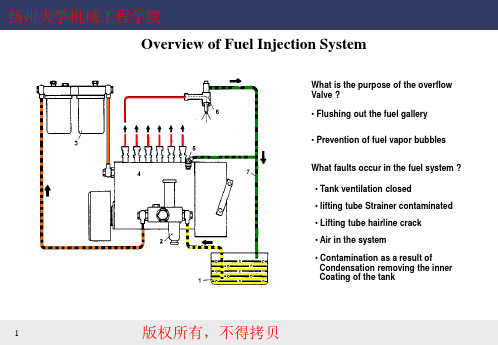
What is the purpose of the overflow Valve ? • Flushing out the fuel gallery • Prevention of fuel vapor bubbles What faults occur in the fuel system ? • Tank ventilation closed • lifting tube Strainer contaminated
9
版权所有,不得拷贝
扬州大学机械工程学院
Quantity
Series of in line pump- P 8000
What is the advantages of scavenging type Fuel gallery ? It avoid oscillation and stabilizes fuel delivery
3
版权所有,不得拷贝
扬州大学机械工程学院
Series of in line is the oil intake for the injection Pump ? Longitudinal bore in the camshaft How is the axial play of the camshaft Adjusted ? It is not adjusted, it is given by bearing play. How is the camshaft protrusion Adjusted ? It is not adjusted Do the bearings have to be changed As a rule after repairs have been Carried out ? Yes
沃尔沃D12-715船用柴油机说明书

Excellent Performance and Cruising RangeThe D12-715 marine diesel engine is spe-c ial l y designed and developed for in s tal -la t ions in fast planing craft fea t ur i ng the lat e st advanced diesel technology. Excellent performance is assured with a rich torque curve matched to the high pow e r output for quick out of the hole ac-c el e r a t ion and high top and cruising speed. Low fuel consumption for long cruising range and low emission levels is assured with:–Electronic Unit Injectors–4-valve technology–Electronically controlled injection tim i ng –High pressure 8-hole injector nozzles–EDC governingThis technology combined optimizesen g ine performance and effi ciency, en s ures effi cient combustion by injecting the right quan t i t y of fuel at the right time, which min-i m iz e s quantity of unburned fuel, re d uc i ng fuel consumption and exhaust emis s ion lev-e ls. The Volvo Penta D12-715 fuel system is designed to give full output regardless of fuel temperature.This technology, in combination with the high power output, gives the boat a wid e r operating range in combination with higher speed.High qualityThe D12-715 is built in the world’s most high l y automated diesel engine factory line with a totally robotic machining and as-s em b ly line with computer controlled audit checks, which ensures the highest quality level.The D12-715 is a further development of the well-proven Volvo Penta in-line six en-g ine concept which ensures high re l i a bil i t y and long term durability.Operation and comfort Electronic remote controls, push button twin engine synchronization and changeof active station ensures easy and smooth op e r a t ion and maneuvering.The electrical control levers are op e r a t e d more smoothly and precisely, requiring much less force.and main t e n ance points contributes tothe ease of ser v ice of the engine.Worldwide service supportin more than 100 countriesThe Volvo Penta parts and servicedeal e r network is a truly internationalop e r a t ion with authorized service deal-e rs around the world. These servicecenters offer Gen u i ne Volvo Penta partsas well as skilled per s on n el to en s ure thebest pos s i b le ser v ice. Con t in u o us andthor o ugh product and ser v ice train i ngen s ures that Vol v o Pen t a prod u cts arewell sup p ort e d.D12-715 – a true marineengine from a true marineengine companyThe D12-715 is a true marine engine asit is developed by a true marine com-p a n y with the best there is to be foundin ma r ine experience and know-how,and built and assembled with the bestpro d uc t ion method there is to be foundin the world.The D12-715 delivers excellent per-f or m ance and cruising range, high re li -abil i t y and durability, in combination withthe high e st level of quality.Automatic twin engine synchronizationre d uc e s noise and vibration levels, andin c reas e s service life of engine.This in combination with the well-bal-a nced D12-715 in-line six cylinder enginewith powerfully dimensioned crankshaftbear i ngs and vibration damper on cam-s haft ensures smooth, vibration-free op-e r a t ion with low noise levels.Low exhaust emissionlevelsThe D12-715 advanced diesel technologygreatly contributes to more effi cient com-b us t ion with higher power and reducednox i ous exhaust emissions.The D12-715 is certifi ed according toIMO.Easy installationThe D12-715 gives a time saving and re-l i a ble installation, as it is a complete de l iv -ered compact and tailor-made propulsionsys t em from one single supplier.Plug-in water-protected harnesses andconnectors, compact dimensions and theEDC system ensures an easy, simple andtime-saving installation.Ease of service andmaintenanceThe EDC system features a self-di a g -nos t ic facility. Easily accessible service* Power rating – see Technical DataD12-715Technical DataEngine designation.......................................D12-715 No. of cylinders and confi guration.............in-line 6 Method of operation.....................................4-stroke,direct-injected, turbocharged diesel engine with aftercooler Bore, mm (in.)............................................131 (5.16) Stroke, mm (in.).........................................150 (5.91) Displacement, l (in3)...........................12.13 (740.2) Compression ratio...........................................16.5:1 Dry weight, kg (lb).................................1400 (3086) Dry weight with reverse gearZF 325A-EB, kg (lb).............................1570 (3461) Crankshaft power,kW (hp) @ 2300 rpm ................................526 (715) Max. torque,Nm (lbf.ft) @ 1600 rpm.......................2925 (2159) Recommended fuel toconform to.........................ASTM-D975 1-D & 2-D, ..............................................EN 590 or JIS KK 2204 Specifi c fuel consumption,g/kWh (lb/hph) @ 2300 rpm................228 (0.369) T echnical data according to ISO 3046 Fuel Stop Power andISO 8665. Fuel with a lower calorifi c value of 42700 kJ/kg and density of 840 g/liter at 15 °C (60 °F). Merchant fuel may differ from this spec ific a t ion which will infl uence engine power output and fuel con s ump t ion.Rating: 5The engine is certifi ed according to IMO.Technical description:Engine and block—Cylinder block and cylinder head made ofcast-iron—One piece cylinder head—Replaceable wet cylinder liners and valve seats/guides—Drop forged crankshaft with induction hard-e ned bearing surfaces and fi llets with sev e n main bearings —Four valve per cylinder layout with over-h ead camshaft—Each cylinder features cross-fl ow in l et andexhaust ducts—Gallery oil-cooled forged aluminum pis t ons—Three piston ringsLubrication system—Integrated oil cooler in cylinder block—Twin full fl ow oil fi lter of spin-on type andby-pass fi lterFuel system—Six Electronic Unit Injectors, one per cyl-i n d er, vertically positioned at the center inbetween the four valves—Gear-driven fuel pump, driven by tim i nggear—Electronically controlled central pro c ess i ngsystem (EDC – Electronic Die s el Con t rol)—Electronically controlled injection tim i ng—8-hole high pressure injector noz z les—Single fi ne fuel fi lter of spin-on type, withwater separatorTurbocharger—Freshwater-cooled turbo chargerCooling system—Freshwater-cooled charge air cooler—Gear-driven coolant pumps—Tubular heat exchanger or single-cir c uitkeel coolingElectrical system—24V electrical system, 24V/60A al t er n a t orReverse gear—ZF 325A-EB, elec t ri c al l y shiftedOptional equipmentContact your Volvo Penta representative.Not all models, standard equipment and accessories are avail-a ble in all countries. All spec ific a t ions are sub j ect to changewithout notice.The engine illustrated may not be entirely identical to pro-d uc t ion standard engines.3-23©23ABVolvoPenta.AB Volvo PentaSE-405 08 Göteborg, SwedenDimensions D12-715 with ZF 325A-EB Not for installationFuel consumptionRpmPower1.Crankshaft pow errpmTorqueRpm。
钻井专业词汇

绪论勘探exploration 开发production顿钻钻井cable drilling旋转钻井Rotary drilling 转盘钻井Rotary drilling顶驱钻井top drive drilling 井下动力钻井hole bottom power drilling 涡轮钻具钻井turbine drilling 螺杆钻具钻井screw drilling旋转钻井钻机Rotary Rig 动力系统(Power System)旋转系统(Rotating System) 提升系统(Hoisting System)循环系统(Circulating System) 井控系统(Well Control System)监测系统 (monitoring System)井架derrick 天车crown block 游动滑车travelling block大钩hook 大绳drilling line 绞车drawworks泥浆泵mud pump泥浆池mud pit 振动筛Vibration Screen防喷器组blowout preventers 地面管汇surface pipeline遥控面板remote control pane 压井管汇kill line钻前准备drill preparation 钻进drilling固井well cementation 完井well completion直井straight/vertical well 定向井directional well水平井horizontal well 浅井shallow well中深井medium-deep well 深井deep well超深井ultra deep well 特超深井super/extra deep well探井exploration well 采油井production well多底井multi-bore well 丛式井cluster well or multiple wells第一章沉积岩sedimentary rock 变质岩metamorphic rock 岩浆岩magmatic rock 岩石的物理机械性质physical-mechanical properties of rock岩石的弹性模量elastic modulus of rock岩石的泊松比rock Poisson’s ratio岩石的切变模量shear modulus of rock抗拉伸强度tension resistance 抗压缩强度 compressive resistance抗剪切强度 shearing resistance 抗弯切强度 bending resistance弹性elasticity 脆性岩石 brittle rock 塑性岩石plastic rock岩石塑性系数rock plasticity coefficient地应力in situ stress 围压confining pressure 有效应力effective stress 压持效应chip hold effect 岩石的可钻性drillability岩石的研磨性rock abrasiveness地层水formation brine比重specific gravity静液压力hydrostatic pressure钻井液压力drilling fluid column pressure 孔隙压力pore pressure地层压力formation fluid pressure地层破裂压力formation fracture pressure上覆岩层压力overburden pressure 基岩应力matrix stress压力梯度pressure gradient 异常压力abnormal pressure压实作用compaction 欠压实作用 undercompaction function机械钻速法penetration rate method d指数法d-exponent methoddc指数法 dc-exponent method 声波时差法acoustic travel time岩石硬度rock hardness漏失试验法leak-off test第二章刮刀钻头(blade bit)牙轮钻头(cone bit)金刚石钻头(diamond bit)天然金刚石钻头(ND)natural diamond人造聚晶金刚石钻头(PDC) polycrystalline diamond compact bit热稳定聚晶金刚石钻头(TSP)thermally stable polycrystalline diamond bit水力结构hydraulic structure 超顶(cone overhang)复锥(offset axis)移轴(multiply cone )钻头的经济指标(economic indicators of bit)钻头进尺(bit footage) 钻头工作寿命(bit operating life)钻头平均机械钻速(bit average rate of penetration)钻头单位进尺成本(cost per singer footage)第三章浮力 buoyancy 钻柱drill stem/string 钻铤drill collar钻杆drill pipe 方钻杆kelly钻头bit 稳定器stabilizerHWDP-厚壁钻杆(Heavy wall drill pipe)复合钻柱combination string中性点neutral point 最大安全静拉力maximum safety static tension第四章钻井液drilling fluids/mud 水基钻井液water-base drilling fluids淡水钻井液fresh-water drilling fluids 低固相钻井液low solids fluids API滤失量API filtration 分散相(dispersion phase )分散介质(dispersion medium)化学处理剂(Chemical treating agent)滤失filtration 滤饼filter cake 含砂量sand content钻井液固相含量solids content in drilling fluids流变方程rheological equation牛顿流体Newtonian fluid 非牛顿流体non- Newtonian fluid塑性流体plastic fluid 幂律流体power law假塑性流体pseudo plastic fluid 膨胀液体expansion fluid钻井液流变性drilling fluids rheology 漏斗粘度funnel viscosity触变性thixotropic behavior 剪切稀释特性(shear thinning)静切力gel strength 动切力yield value 塑性粘度Plastic Viscosity动塑比ratio of yield value to plastic viscosity初切力initial gel strength 终切力10-minuto gel strength固相控制solid control 钻屑cutting 砂sand 泥silt压差卡钻(differential pressure sticking)井漏(lost circulation )井塌(borehole collapse) 钻井液污染(drilling fluid contamination ) 第五章井眼轨道(well trajectory)井眼轨迹(well track)井深Measure Depth 井斜角inclination/deviation angel方位角azimuth angle井斜变化率rate of deviation 方位变化率rate of azimuth井眼曲率hole curvature垂深True vertical depth(TVD)水平投影长度horizontal projection length (hole deviation)水平位移horizontal displacement平移方位角(translational azimuth) N坐标和E坐标(N-coordinate & E-coordinate)视平移(apparent horizontal displacement )水平投影图(horizontal projection)垂直投影图(vertical projection)垂直剖面图(vertical cross section )直井段(Vertical section)ok造(增)斜段(build section) kb稳斜段(hold section ) bh降斜段(drop section) hd目标点(target point)靶区及靶区半径(target area) rt 靶心距(off-target distance) St造斜点(kick off point) k 二维定向井Two-dimensional directional well三维定向井Three-dimensional directional well第六章喷射式钻头jet bit 射流喷速jet velocity射流冲击力jet impact force 射流水功率jet hydraulic-power钻头压降bit pressure-drop钻头水功率bit hydraulic horse-power钻井泵的工作状态the working regime of drilling pump额定泵压rated pump pressure额定功率rated pump power循环压耗circulating pressure loss 优选标准optimization standard钻压weight on bit转速rpm-revolution per minute 排量rate of flow 进尺footage 喷嘴nozzle钻速方程drilling rate equation /model第七章测斜deviational survey 平均角法average angle method曲率半径法radius of curvature method 井斜well deviation满眼钻具packed hole assembly 钟摆钻具pendulum assembly钟摆力pendulum force井底动力钻具bottomhole motor转盘钻 rotary drill 工具面角tool face orientation装置方位角tool face azimuth 定向方位角Directional azimuth反扭角reactive torque angle第八章地层井眼系统的压力平衡 balance of formation-borehole system地层压力当量钻井液密度equivalent drilling fluid density钻井液当量循环密度equivalent circulating density波动压力(激动压力)surge pressure 抽汲压力swabbing pressure井侵 influx 溢流overflow 井涌kick 井喷well blowout地下井喷underground blowout 井喷失控out of control for blowout正压差positive differential pressure负压差negative differential pressure平衡钻井balanced drillin g 欠平衡under balanced drilling近平衡near balanced drilling 过平衡over balanced drilling关井shut in 防喷器blow out preventer 地面管汇surface drill pipe环形空间annulus 压井killing well 硬关井hard closing软关井soft closing 压井方法killing well method工程师法(等待加重量法)engineer’s method司钻法(二次循环法)driller’s method第九章套管程序casing program导管conductor 表层套管surface casing技术套管intermediate casing strings 生产套管production casing 尾管line 钻井尾管drilling liner 生产尾管production liner套管接箍casing coupling套管柱casing string 前置液ahead fluid隔离液spacer fluid 冲洗液flushing fluid套管的外载荷outside casing load 套管内压力burst套管外挤压力collapse pressure 套管轴向力axial load套管强度casing strength 套管抗挤强度collapse resistance套管抗拉强度tensile resistance 套管抗内压强度burst resistance完井方法completion methods 裸眼完井法open hole completion先期裸眼完井法initial open hole completion后期裸眼完井法final open hole completion射孔完井法perforation completion衬管完井法slotted liner completion砾石充填完井法gravel pack completion固井质量cement job quality 固井质量评价cement evaluation窜槽cement channeling 顶替效率displacement efficiency尾管固井drilling liner cementing 尾管悬挂器drilling liner hanger井口装置wellhead 油管头tubing head 套管头casing head采油树Christmas tree稠化时间thickening time 凝结时间setting time。
模具专业英语词汇

入水:gate进入位:gate location水口形式:gate type大水口:edge gate细水口: pin-point gate水口大小:gate size转水口:switching runner/gate唧嘴口径:spray diameter流道: runner热流道:hot runner, hot manifold 热嘴冷流道: hot spray/cold runner唧嘴直流: direct spray gate圆形流道:round(full/half runner流道电脑分析:mold flow analysis流道平衡:runner balance热嘴:hot spray热流道板:hot manifold发热管:cartridge heater探针: thermocouples插头:connector plug插座: connector socket密封/封料: seal运水:water line喉塞:line plug喉管:tube塑胶管:plastic tube快速接头:jiffy quick connector plug 模具零件:mold components三板模:3-plate mold二板模:2-plate mold边钉/导边:leader pin/guide pin边司/导套:bushing/guide bushing中托司:shoulder guide bushing中托边L:guide pin顶针板:ejector retainner plate托板:support plate螺丝: screw管钉:dowel pin开模槽:ply bar slot模管位:core/cavity inter-lock顶针:ejector pin司筒:ejector sleeve司筒针:ejector pin 模具专业英语推板:stripper plate缩呵:movable core, return core puller 扣机(尼龙拉勾):nylon latch lock斜顶:lifter模胚(架): mold base上模:cavity insert下模:core insert行位(滑块): slide镶件:insert压座/斜楔:wedge耐磨板/油板:wedge wear plate压条:plate撑头: support pillar唧嘴: sprue bushing挡板:stop plate定位圈:locating ring锁扣:latch扣鸡:parting lock set推杆:push bar栓打螺丝:S.H.S.Binjection nozzle 射出喷嘴顶板:eracuretun活动臂:lever arm分流锥:spure sperader水口司:bush垃圾钉:stop pin隔片:buffle弹弓柱:spring rod弹弓:die spring中托司:ejector guide bush中托边:ejector guide pin镶针:pin销子:dowel pin波子弹弓:ball catch喉塞: pipe plug锁模块:lock plate斜顶:angle from pin斜顶杆:angle ejector rod尼龙拉勾:parting locks活动臂:lever arm复位键、提前回杆:early return bar气阀:valves斜导边:angle pin术语:terms承压平面平衡:parting surface support balance模排气:parting line venting回针碰料位:return pin and cavity interference模总高超出啤机规格:mold base shut hight 顶针碰运水:water line interferes withejector pin料位出上/下模:part from cavith (core) side模胚原身出料位:cavity direct cut on A-plate,core direct cut on B-plate.不准用镶件: Do not use (core/cavity) insert用铍铜做镶件: use beryllium copper insert 初步(正式)模图设计:preliinary (final) mold design反呵:reverse core弹弓压缩量:spring compressed length 稳定性好:good stability, stable强度不够:insufficient rigidity均匀冷却:even cooling扣模:sticking热膨胀:thero expansion公差:tolerance铜公(电极):copper electrodebrasive grinding 强力磨削abrasive 磨料的,研磨的absence 不在,缺席accessory 附件accommodate 适应accordingly 因此,从而,相应地accuracy 精度,准确性actuate 开动(机器),驱动adequate 足够的adhesive 粘合剂adjacent 邻近的adopt 采用advance 进步advisable 可取的agitate 摇动a large extent 很大程度algorithm 算法align 定位,调准alignment 校直all-too-frequent 频繁allowance 容差,余量alternate 交替,轮流alternatively 选择,也许aluminium 铝ample 充足的analysis 分析ancillary 补助的,副的angular 有角的annealing 退火aperture 孔applied loads 作用力appropriate 适当的arc 弧,弓形arise 出现,发生arrange 安排article 制品,产品ascertain 确定,查明assemble 组装attitude 态度auxiliary 辅助的avoid 避免axis 轴axle 轮轴,车轴alternative 替换物backup 备份batch 一批bearing 轴承,支座bed 床身behavior 性能bench-work 钳工工作bend 弯曲beneath 在•••下bin 仓,料架blank 坯料blank 冲裁,落料blanking 落料模blast 一阵(风)blemish 缺点,污点bolster 模座,垫板boring 镗削,镗孔bracket 支架brass 黄铜break down 破坏breakage 破坏brine 盐水brittle 易碎的buffer 缓冲器built-in 装的bulging 凸肚burr 毛刺bush 衬套by far •••得多,最by means of 借助于boost 推进cabinet 橱柜call upon 要求carbide 碳化物carburzing 渗碳carriage 拖板,大拖板carry along 一起带走carry down over 从•••上取下carry out 完成case hardening 表面硬化case 壳,套cast steel 铸钢casting 铸造,铸件category 种类caution 警告,警示cavity and core plates 凹模和凸模板cavity 型腔,腔,洞centre-drilling 中心孔ceramic 瓷制品chain doted line 点划线channel 通道,信道characteristic 特性check 核算chip 切屑,铁屑chuck 卡盘chute 斜道circa 大约circlip (开口)簧环circuit 回路,环路circulate (使)循环clamp 夹紧clamp 压板clay 泥土clearance 间隙clip 切断,夹住cold hobbing 冷挤压cold slug well 冷料井collapse 崩塌,瓦解collapsible 可分解的combination 组合commence 开始,着手commence 开始commercial 商业的competitive 竞争的complementary 互补的complexity 复杂性complication 复杂化compression 压缩comprise 包含compromise 妥协,折衷concern with 关于concise 简明的,简练的confront 使面临connector 连接口,接头consequent 随之发生的,必然的console 控制台consume 消耗,占用consummate 使完善container 容器contingent 可能发生的CPU (central processing unit) 中央处理器conventional 常规的converge 集中于一点conversant 熟悉的conversion 换算,转换conveyer 运送装置coolant 冷却液coordinate (使)协调copy machine 仿形(加工)机床core 型芯,核心corresponding 相应的counteract 反作用,抵抗couple with 伴随contour 轮廓crack (使)破裂,裂纹critical 临界的cross-hatching 剖面线cross-section drawn 剖面图cross-slide 横向滑板CRT (cathoder-ray tube) 阴极射线管crush 压碎cryogenic 低温学的crystal 结晶状的cubic 立方的,立方体的cup (使)成杯状,引伸curable 可矫正的curvature 弧线curve 使弯曲cutter bit 刀头,刀片cyanide 氰化物complicated 复杂的dash 破折号daylight 板距decline 下落,下降,减少deform (使)变形demonstrate 证明depict 描述deposite 放置depression 凹穴descend 下降desirable 合适的detail 细节,详情deterioration 退化,恶化determine 决定diagrammmatic 图解的,图表的dictate 支配die 模具,冲模,凹模dielectric 电介质die-set 模架digital 数字式数字dimensional 尺寸的,空间的discharge 放电,卸下,排出discharge 卸下discrete 离散的,分立的dislodge 拉出,取出dissolution 结束distinct 不同的,显著的distort 扭曲distort (使)变形,扭曲distributed system 分布式系统dowel 销子dramaticlly 显著地drastic 激烈的draughting 绘图draughtsman 起草人drawing 制图drill press 钻床drum 鼓轮dual 双的,双重的ductility 延展性dynamic 动力的edge 边缘e.g.(exempli gratia) [拉]例如ejector 排出器ejector plate 顶出板ejector rob 顶杆elasticity 弹性electric dicharge machining 电火花加工electrode 电极electro-deposition 电铸elementary 基本的eliminate 消除,除去elongate (使)伸长,延长emerge 形成,显现emphasise 强调endeavour 尽力engagement 约束,接合enhance 提高,增强ensure 确保,保证erase 抹去,擦掉evaluation 评价,估价eventually 终于evolution 进展excecution 执行,完成execute 执行electrochemical machining 电化学加工exerte 施加experience 经验explosive 爆炸(性)的extend 伸展external 外部的extract 拔出extreme 极端extremely 非常地extremity 极端extrusion 挤压,挤出envisage 设想Fahrenheit 华氏温度fabricate 制作,制造flat-panel technology 平面(显示)技术facility 设备facing 端面车削fall within 属于,适合于fan 风扇far from 毫不,一点不,远非fatigue 疲劳feasible 可行的feature 特色,特征feed 进给feedback 反馈female 阴的,凹形的ferrule 套管file system 文件系统fitter 装配工,钳工fix 使固定,安装fixed half and moving half 定模和动模facilitate 帮助flexibility 适应性,柔性flexible 柔韧的flow mark 流动斑点follow-on tool 连续模foregoing 在前的,前面的foretell 预测,预示,预言forge 锻造forming 成型four screen quadrants 四屏幕象限fracture 破裂free from 免于gap 裂口,间隙gearbox 齿轮箱govern 统治,支配,管理grain 纹理graphic 图解的grasp 抓住grid 格子,网格grind 磨,磨削,研磨grinding 磨光,磨削grinding machine 磨床gripper 抓爪,夹具groove 凹槽guide bush 导套guide pillar 导柱guide pillars and bushes 导柱和导套handset 听筒hardness 硬度hardware 硬件headstock 床头箱,主轴箱hexagonal 六角形的,六角的hindrance 障碍,障碍物hob 滚刀,冲头hollow-ware 空心件horizontal 水平的hose 软管,水管hyperbolic 双曲线的i.e. (id est) [拉]也就是identical 同样的identify 确定,识别idle 空闲的immediately 正好,恰好impact 冲击impart 给予implement 实现impossibility 不可能impression 型腔in contact with 接触in terms of 依据inasmuch (as) co因为,由于inch-to-metric conversions 英公制转换inclinable 可倾斜的inclusion 含物inconspicuous 不显眼的incorporate 合并,混合indentation 压痕indenter 压头independently 独自地,独立地inevitably 不可避免地inexpensive 便宜的inherently 固有的injection mould 注塑模injection 注射in-line-of-draw 直接脱模insert 嵌件inserted die 嵌入式凹模inspection 检查,监督installation 安装integration 集成intelligent 智能的intentinonally 加强地,集中地interface 界面internal 部的interpolation 插值法investment casting 熔模铸造irregular 不规则的,无规律irrespective of 不论,不管irrespective 不顾的,不考虑的issue 发布,发出joint line 结合线kerosene 煤油keyboard 健盘knock 敲,敲打lance 切缝lathe 车床latitude 自由lay out 布置limitation 限度,限制,局限(性) local intelligence 局部智能locate 定位logic 逻辑longitudinal 纵向的longitudinally 纵向的look upon 视作,看待lubrication 润滑machine shop 车间machine table 工作台machining 加工made-to-measure 定做maintenance 维护,维修majority 多数make use of 利用male 阳的,凸形的malfunction 故障mandrel 心轴manifestation 表现,显示massiveness 厚实,大块measure 大小,度量microcomputer 微型计算机microns 微米microprocessor 微处理器mild steel 低碳钢milling machine 铣床mineral 矿物,矿产minimise 把减到最少,最小化minute 微小的mirror image 镜像mirror 镜子moderate 适度的modification 修改,修正modulus 系数mold 模,铸模mold 制模,造型monitor 监控monograph 专著more often than not 常常motivation 动机mould split line 模具分型线moulding 注塑件move away from 抛弃multi-imprssion mould 多型腔模narrow 狭窄的NC (numerical control) 数控nevertheless 然而,不过nonferrous 不含铁的,非铁的normally 通常地novice 新手,初学者nozzle 喷嘴,注口numerical 数字的objectionable 有异议的,讨厌的observe 观察obviously 明显地off-line 脱机的on-line 联机operational 操作的,运作的opportunity 时机,机会opposing 对立的,对面的opposite 反面optimization 最优化orient 确定方向orthodox 正统的,正规的overall 全面的,全部的overbend 过度弯曲overcome 克服,战胜overlaping 重叠overriding 主要的,占优势的opposite 对立的,对面的pack 包装package 包装pallet 货盘panel 面板paraffin 石蜡parallel 平行的penetration 穿透peripheral 外围的periphery 外围permit 许可,允许pessure casting 压力铸造pillar 柱子,导柱pin 销,栓,钉pin-point gate 针点式浇口piston 活塞plan view 主视图plasma 等离子plastic 塑料platen 压板plotter 绘图机plunge 翻孔plunge 投入plunger 柱塞pocket-size 袖珍portray 描绘pot 壶pour 灌,注practicable 行得通的preferable 更好的,更可取的preliminary 初步的,预备的press setter 装模工press 压,压床,冲床,压力机prevent 妨碍primarily 主要地procedure 步骤,方法,程序productivity 生产力profile 轮廓progressively 渐进地project 项目project 凸出projection 突出部分proper 本身的property 特性prototype 原形proximity 接近prudent 谨慎的punch 冲孔punch shapper tool 刨模机punch-cum-blanking die 凹凸模punched tape 穿孔带purchase 买,购买push back pin 回程杆pyrometer 高温计quality 质量quandrant 象限quantity 量,数量quench 淬火radial 放射状的ram 撞锤rapid 迅速的rapidly 迅速地raster 光栅raw 未加工的raw material 原材料ream 铰大reaming 扩孔,铰孔recall 记起,想起recede 收回,后退recess 凹槽,凹座,凹进处redundancy 过多re-entrant 凹入的refer 指,涉及,谈及reference 参照,参考refresh display 刷新显示register ring 定位环register 记录,显示,记数regrind 再磨研relative 相当的,比较的relay 继电器release 释放relegate 把降低到reliability 可靠性relief valves 安全阀relief 解除relieve 减轻,解除remainder 剩余物,其余部分removal 取出remove 切除,切削reposition 重新安排represent 代表,象征reputable 有名的,受尊敬的reservoir 容器,储存器resident 驻存的resist 抵抗resistance 阻力,抵抗resolution 分辨率respective 分别的,各自的respond 响应,作出反应responsibility 责任restrain 抑制restrict 限制,限定restriction 限制retain 保持,保留retaining plate 顶出固定板reveal 显示,展现reversal 反向right-angled 成直角的rigidity 钢度rod 杆,棒rotate (使)旋转rough machining 粗加工rough 粗略的routine 程序rubber 橡胶runner and gate systems 流道和浇口系统sand casting 砂型铸造satisfactorily 满意地saw 锯子scale 硬壳score 刻划scrap 废料,边角料,切屑screwcutting 切螺纹seal 密封section cutting plane 剖切面secure 固定secure 紧固,夹紧,固定segment 分割sensitive 敏感的sequence 次序sequential 相继的seriously 严重地servomechanism 伺服机构servomotor 伺服马达setter 安装者set-up 机构sever 切断severity 严重shaded 阴影的shank 柄shear 剪,切shot 注射shrink 收缩side sectional view 侧视图signal 信号similarity 类似simplicity 简单single-point cutting tool 单刃刀具situate 使位于,使处于slide 滑动,滑落slideway 导轨slot 槽slug 嵌条soak 浸,泡,均热software 软件solid 立体,固体solidify (使)凝固solidify (使)固化solution 溶液sophisiticated 尖端的,完善的sound 结实的,坚固的spark erosion 火花蚀刻spindle 主轴spline 花键split 侧向分型,分型spool 线轴springback 反弹spring-loaded 装弹簧的sprue bush 主流道衬套sprue puller 浇道拉杆square 使成方形Servomechanism Laboratoies 伺服机构实验室stage 阶段standardisation 标准化startling 令人吃惊的steadily 稳定地step-by-step 逐步stickiness 粘性stiffness 刚度stock 毛坯,坯料storage tube display 储存管显示storage 储存器straightforward 直接的strain 应变strength 强度stress 压力,应力stress-strain 应力--应变stretch 伸展strike 冲击stringent 严厉的stripper 推板stroke 冲程,行程structrural build-up 结构上形成的sub-base 垫板subject 使受到submerge 淹没subsequent 后来的subsequently 后来,随后substantial 实质的substitute 代替,替换subtract 减,减去suitable 合适的,适当的suitably 合适地sunk 下沉,下陷superior 上好的susceptible 易受影响的sweep away 扫过symmetrical 对称的synchronize 同步,同时发生tactile 触觉的,有触觉的tailstock 尾架tapered 锥形的tapping 攻丝technique 技术tempering 回火tendency 趋向,倾向tensile 拉力的,可拉伸的tension 拉紧,紧terminal 终端机terminology 术语,用辞theoretically 理论地thereby 因此,从而thermoplastic 热塑性的thermoplastic 热塑性塑料thermoset 热固性thoroughly 十分地,彻底地thread pitch 螺距thread 螺纹thrown up 推上tilt 倾斜,翘起tolerance 公差two-plate mould 双板式注射模tong 火钳tonnage 吨位,总吨数tool point 刀锋tool room 工具车间toolholder 刀夹,工具柄toolmaker 模具制造者toolpost grinder 工具磨床toolpost 刀架torsional 扭转的toughness 韧性trace 追踪transverse 横向的tray 盘,盘子,蝶treatment 处理tremendous 惊人的,巨大的trend 趋势trigger stop 始用挡料销tungsten 钨turning 车削twist 扭曲,扭转tracer-controlled milling machine 仿形铣床ultimately 终于undercut mould 侧向分型模undercut 侧向分型undercut 底切underfeed 底部进料的undergo 经受underside 下面,下侧undue 不适当的,过度的uniform 统一的,一致的utilize 利用Utopian 乌托邦的,理想化的valve 阀vaporize 汽化vaporize (使)蒸发variation 变化various 不同的,各种的vector feedrate computation 向量进刀速率计算vee 字形velocity 速度versatile 多才多艺的,万用的vertical 垂直的via prep经,通过vicinity 附近viewpoint 观点wander 偏离方向warp 翘曲washer 垫圈wear 磨损well line 结合线whereupon 于是winding 绕,卷with respect to 相对于withstand 经受,经得起work 工件workstage 工序wrinkle 皱纹使皱yield 生产zoom 图象电子放大runner less mold 无流道模hot runner mold 热流道模insulated runner mold 绝热流道模warm runner mold 温流道模runner plate 流道板warm runner plate 温流道板sprue 直浇道,主流道,浇口runless injiection 无流道冷料模具hot-runner mold 热流道模具runner ejector set 流道顶出器runner lock pin 流道拉梢shoot 流道die block steel 模具钢die material 模具材料cold work tool (die) steel 冷作工具(模具)钢hot work tool (die) steel 热作工具(模具)钢holder of punch 凸模夹持器die slide 下模滑动装置turret press 冲模回转压力机blanking die 冲裁模piercing die 冲孔模die,stamping and punching die 冲模die life 冲模寿命die shut height 模具闭合高度clearance between punch and die 凹凸模间隙peak die load 模具最大负荷matrix plate凹模固定板clearance between punch and die 凹凸模间隙matrix plate 凹模固定板cavity plate (block) 凹模die block凸模固定板button die 镶入式圆形凸模gib 凹形拉紧销spanishing凹痕印刷concave angle 凹角concave cutter 凹面铣刀depression 外缩凹孔sinking 凹陷single redessed单面缩凹形clamp-off 铸件凹痕riding 凹陷holder of punch 凸模夹持器clearance between punch and die凹凸模间隙counter punch反凸模angular cams 角凸轮flanged pin 带凸缘销weld flush焊缝凸起flange joint凸缘接头flange connection 凸缘联接convex cutter 凸形铣刀belling 压凸加工cam die bending 凸轮弯曲加工flabging 凸缘加工lug 凸缘crowing 中凸研磨flage wrinkel 凸缘起皱bent pilot 弯曲导正销baffle 导流块ejector guide pin 推板导柱ejector guide bush 板导推套dowel hole 导套孔ejector guide pin 顶出导梢ejector leader busher顶出导梢衬套guide bushing 引导衬套guide pin导梢guide plate 导板guide post 引导柱guide rail 导轨locating pilot pin 定位导梢pass guide穴型导板pilot pin 导销die slide下模滑动装置outer slide外滑块ball silder 球塞滑块slide(slide core) 滑块slip joint 滑配接头snap fit 滑入配合Screw thread lubricant 螺纹润滑剂drawing with ironing 抽引光滑加工dulling平滑glazing光滑剂shot chamber 注射室shot volume 注射量,压注量shot capacity 注射能力injection pressure压射比压,注射压力injection speed 注射速度injection forming 注射成形injection speed 注射速度injection mold 注射模injection mold for thermosets 热固性塑料注射模injection mold for thermoplastics 热塑性塑料注射模shot volume 注射量,压注量shot注射(射次)return-blank type blanking die顶出式落料模ejector guide pin 顶出导梢ejector pad 顶出垫ejector pin顶出梢ejector plate顶出板ejector rod 顶出杆ejector stopper 顶出止动ejector valve 顶出阀ejection pad 顶出衬垫ejector leader busher 顶出导梢衬套head punch 顶镦冲头lifting pin起模顶销pre extrusion punch顶挤冲头runner ejector set 流道顶出器prehardened steel 顶硬钢core-pulling force 抽芯力ejector guide pin 推板导柱ejector guide bush 板导推套ejector pin (plate) 推杆(板)ejector sleeve 推管ejector pin retaining plate 推杆固定板puncher 推杆taper key 推拔键thrust pin 推力销plain tapered bore 普通推拔孔taper shank推拔柄taper tap推拔螺丝攻sprue puller 拉料杆。
真空气雾化法制备AlSi10Mg_粉末参数优化及打印态组织性能研究
精 密 成 形 工 程第16卷 第2期 96JOURNAL OF NETSHAPE FORMING ENGINEERING 2024年2月收稿日期:2024-01-10 Received :2024-01-10基金项目:中煤科工集团上海有限公司科研开发项目(020********Y )Fund :Scientific Research and Development Project of Middling Coal Technology and Industry Group Shanghai Co., Ltd. (020********Y)引文格式:蒋保林, 蒋崴, 许荣玉, 等. 真空气雾化法制备AlSi10Mg 粉末参数优化及打印态组织性能研究[J]. 精密成形工程, 2024, 16(2): 96-103.JIANG Baolin, JIANG Wei, XU Rongyu, et al. Optimization of Parameters and Printed Microstructure and Properties of AlSi10Mg Powder Prepared by Vacuum Atomization Method[J]. Journal of Netshape Forming Engineering, 2024, 16(2): 96-103. *通信作者(Corresponding author ) 真空气雾化法制备AlSi10Mg 粉末参数优化及打印态组织性能研究蒋保林1,蒋崴2,许荣玉1*,陈烜3,吕复强2,赵永柱2,付珂2,陈正2(1.江苏威拉里新材料科技有限公司,江苏 徐州 221000;2.中国矿业大学 材料与物理学院,江苏 徐州 221000;3.常熟天地煤机装备有限公司,江苏 苏州 215500) 摘要:目的 探究利用真空气雾化法制备AlSi10Mg 球形粉末过程中各参数对粉末质量的影响,以得到最佳的制粉工艺参数。
2010-26-EU-欧盟新排放指令

DIRECTIVESCOMMISSION DIRECTIVE 2010/26/EUof 31 March 2010amending Directive 97/68/EC of the European Parliament and of the Council on the approximation of the laws of the Member States relating to measures against the emission of gaseous and particulate pollutants from internal combustion engines to be installed in non-road mobile machinery(Text with EEA relevance)THE EUROPEAN COMMISSION, Having regard to the Treaty on the Functioning of the European Union,Having regard to Directive 97/68/EC of 16 December 1997 of the European Parliament and of the Council on the approxi mation of the laws of the Member States relating to measures against the emission of gaseous and particulate pollutants from internal combustion engines to be installed in non-road mobile machinery ( 1 ), and in particular Articles 14 and 14a thereof, Whereas:(1) Article 14a of Directive 97/68/EC sets out the criteria and the procedure for extending the period referred to in Article 9a(7) of that Directive. Studies carried out in accordance with Article 14a of Directive 97/68/EC show that there are substantial technical difficulties to comply with stage II requirements for professional use, multi- positional, hand-held mobile machinery in which engines of classes SH:2 and SH:3 are installed. It is therefore necessary to extend the period referred to in Article 9a(7) until 31 July 2013. (2) Since the amendment of Directive 97/68/EC in 2004, technical progress has been made in the design of diesel engines with a view to make them compliant with the exhaust emission limits for stages IIIB and IV. Electronically controlled engines, largely replacing me- chanically controlled fuel injection and control systems, have been developed. Therefore, the current general type- approval requirements in Annex I to Directive 97/68/EC should be adapted accordingly and general type-approval requirements for stages IIIB and IV should be introduced. (3) Annex II to Directive 97/68/EC specifies the technical details of the information documents that need to be submitted by the manufacturer to the type-approval authority with the application for engine type-approval. The details specified regarding the additional anti- pollution devices are generic and should be adapted to the specific after-treatment systems that need to be used to ensure that engines comply with exhaust emission limit stages IIIB and IV. More detailed information on the after-treatment devices installed on the engines should be submitted to enable type-approval authorities to assess the engine’s capability to comply with stages IIIB and IV.(4) Annex III to Directive 97/68/EC sets out the methodtesting the engines and determining their level of emissions of gaseous and particulate pollutants. The type-approval testing procedure of engines to demon strate compliance with the exhaust emission limits of stage IIIB and IV should ensure that the simultaneous compliance with the gaseous (carbon monoxide, hydro carbons, oxides of nitrogen) and the particulate emission limits is demonstrated. The non-road steady cycle (NRSC) and non-road transient cycle (NRTC) should be adapted accordingly. (5) Point 1.3.2 of Annex III to Directive 97/68/EC foreseesthe modification of the symbols (section 2.18 of Annex I), the test sequence (Annex III) and calculation equations (Appendix III to Annex III), prior to the introduction of the cold/hot composite test sequence. The type approval procedure to demonstrate compliance with the exhaust emission limits of stage IIIB and IV requires the intro duction of a detailed description of the cold start cycle. (6) Section 3.7.1 of Annex III to Directive 97/68/EC sets out the test cycle for the different equipment specifications. The test cycle under point 3.7.1.1 (specification A) needs to be adapted to clarify which engine speed needs to be used in the type approval calculation method. It is also necessary to adapt the reference to the updated version of the international testing standard ISO 8178-4:2007.( 1 ) OJ L 59, 27.2.1998, p. 1.(7) Section 4.5 of Annex III to Directive 97/68/EC outlines the emissions test run. This section needs to be adapted to take account of the cold start cycle. (8) Appendix 3 of Annex III to Directive 97/68/EC sets out the criteria for the data evaluation and calculation of the gaseous emissions and the particulate emissions, for both the NRSC test and the NRTC test set out in Annex III. The type approval of engines in accordance with stage IIIB and IV requires the adaptation of the calculation method for the NRTC test. (9) Annex XIII to Directive 97/68/EC sets out the provisions for engines placed on the market under a ‘flexible scheme’. To ensure a smooth implementation of stage IIIB, an increased use of this flexibility scheme may be needed. Therefore, the adaptation to technical progress to enable the introduction of stage IIIB compliant engines needs to be accompanied by measures to avoid that the use of the flexibility scheme may be hampered by notifi cation requirements which are no longer adapted to the introduction of such engines. The measures should aim at simplifying the notification requirements and the reporting obligations, and at making them more focused and tailored to the need for market surveillance authorities to respond to the increased use of the flexi bility scheme that will result from the introduction of stage IIIB. (10) Since Directive 97/68/EC provides for the type-approval of stage IIIB engines (category L) as from 1 January 2010 it is necessary to provide for the possibility to grant type approval from that date. (11) For reasons of legal certainty this Directive should enter into force as a matter of urgency. (12) The measures provided for in this Directive are in accordance with the opinion of the Committee estab lished in Article 15(1) of Directive 97/68/EC, HAS ADOPTED THIS DIRECTIVE: Article 1 Amendments to Directive 97/68/EC Directive 97/68/EC is amended as follows: 1. in Article 9a(7), the following subparagraph is added: ‘Notwithstanding the first subparagraph, an extension of the derogation period is granted until 31 July 2013, within the category of top handle machines, for professional use, multi- positional, hand-held hedge trimmers and top handle tree service chainsaws in which engines of classes SH:2 and SH:3 are installed.’;2. Annex I is amended in accordance with Annex I to this Directive;3. Annex II is amended in accordance with Annex II to this Directive;4. Annex III is amended in accordance with Annex III to this Directive;5. Annex V is amended in accordance to Annex IV to this Directive;6. Annex XIII is amended in accordance with Annex V to this Directive.Article 2Transitional provisionWith effect from the day following the publication of this Directive in the Official Journal, Member States may grant type-approval in respect of electronically controlled engines which comply with the requirements laid down in Annexes I, II, III, V and XIII to Directive 97/68/EC, as amended by this Directive.Article 3Transposition1. Member States shall bring into force the laws, regulations and administrative provisions necessary to comply with the Directive within 12 months after the publication of the Directive. They shall forthwith communicate to the Commission the text of those provisions.They shall apply those provisions from 31 March 2011.When Member States adopt those provisions, they shall contain a reference to this Directive or be accompanied by such a reference on the occasion of their official publication. Member States shall determine how such reference is to be made.2. Member States shall communicate to the Commission the text of the main provisions of national law which they adopt in the field covered by this Directive.Article 4Entry into forceThis Directive shall enter into force on the day following its publication in the Official Journal of the European Union .Article 5AddresseesThis Directive is addressed to the Member States. Done at Brussels, 31 March 2010. For the Commission The President José Manuel BARROSOANNEX IThe following section 8 is added to Annex I to Directive 97/68/EC:IIIBIVSTAGESANDFOR‘8. TYPEAPPROVALREQUIREMENTS8.1. This section shall apply to the type-approval of electronically controlled engines, which uses electronic control todetermine both the quantity and timing of injecting fuel (hereafter “engine”). This section shall apply irrespective of the technology applied to such engines to comply with the emission limit values set out in sections 4.1.2.5 and 4.1.2.6 of this Annex.8.2. DefinitionsFor the purpose of this section, the following definitions shall apply:8.2.1. “emission control strategy” means a combination of an emission control system with one base emission controlstrategy and with one set of auxiliary emission control strategies, incorporated into the overall design of an engine or non-road mobile machinery into which the engine is installed.8.2.2. “reagent” means any consumable or non-recoverable medium required and used for the effective operation of theexhaust after-treatment system.8.3. Generalrequirements8.3.1. Requirements for base emission control strategy8.3.1.1. The base emission control strategy, activated throughout the speed and torque operating range of the engine,shall be designed as to enable the engine to comply with the provisions of this Directive8.3.1.2. Any base emission control strategy that can distinguish engine operation between a standardised type approvaltest and other operating conditions and subsequently reduce the level of emission control when not operating under conditions substantially included in the type approval procedure is prohibited.8.3.2. Requirements for auxiliary emission control strategy8.3.2.1. An auxiliary emission control strategy may be used by an engine or a non-road mobile machine, provided thatthe auxiliary emission control strategy, when activated, modifies the base emission control strategy in response toa specific set of ambient and/or operating conditions but does not permanently reduce the effectiveness of theemission control system:(a) where the auxiliary emission control strategy is activated during the type approval test, sections 8.3.2.2 and8.3.2.3 shall not apply;(b) where the auxiliary emission control strategy is not activated during the type approval test, it must bedemonstrated that the auxiliary emission control strategy is active only for as long as required for thepurposes identified in section 8.3.2.3.8.3.2.2. The control conditions applicable to this section are all of the following:(a) an altitude not exceeding 1 000 metres (or equivalent atmospheric pressure of 90 kPa);(b) an ambient temperature within the range 275 K to 303 K (2 °C to 30 °C);(c) the engine coolant temperature above 343 K (70 °C).Where the auxiliary emission control strategy is activated when the engine is operating within the control conditions set out in points (a), (b) and (c), the strategy shall only be activated exceptionally.8.3.2.3. An auxiliary emission control strategy may be activated in particular for the following purposes:(a) by onboard signals, for protecting the engine (including air-handling device protection) and/or non-roadmobile machine into which the engine is installed from damage;(b) for operational safety and strategies;(c) for prevention of excessive emissions, during cold start or warming-up, during shut-down;(d) if used to trade-off the control of one regulated pollutant under specific ambient or operating conditions, formaintaining control of all other regulated pollutants, within the emission limit values that are appropriate forthe engine concerned. The purpose is to compensate for naturally occurring phenomena in a manner thatprovides acceptable control of all emission constituents.8.3.2.4. The manufacturer shall demonstrate to the technical service at the time of the type-approval test that theoperation of any auxiliary emission strategy complies with the provisions of section 8.3.2. The demonstration shall consist of an evaluation of the documentation referred to in section 8.3.3.8.3.2.5. Any operation of an auxiliary emission control strategy not compliant with section 8.3.2 is prohibited.8.3.3. Documentation requirements8.3.3.1. The manufacturer shall provide an information folder accompanying the application for type-approval at thetime of submission to the technical service, which ensures access to any element of design and emission control strategy and the means by which the auxiliary strategy directly or indirectly controls the output variables. The information folder shall be made available in two parts:(a) the documentation package, annexed to the application for type-approval, shall include a full overview of theemission control strategy. Evidence shall be provided that all outputs permitted by a matrix, obtained fromthe range of control of the individual unit inputs, have been identified. This evidence shall be attached to theinformation folder as referred to in Annex II;(b) the additional material, presented to the technical service but not annexed to the application for type-approval, shall include all the modified parameters by any auxiliary emission control strategy and theboundary conditions under which this strategy operates and in particular:(i) a description of the control logic and of timing strategies and switch points, during all modes ofoperation for the fuel and other essential systems, resulting in effective emissions control (such asexhaust gas recirculation system (EGR) or reagent dosing);(ii) a justification for the use of any auxiliary emission control strategy applied to the engine, accompanied by material and test data, demonstrating the effect on exhaust emissions. This justification may be basedon test data, sound engineering analysis, or a combination of both;(iii) a detailed description of algorithms or sensors (where applicable) used for identifying, analysing, or diagnosing incorrect operation of the NO x control system;(iv) the tolerance used to satisfy the requirements in section 8.4.7.2, regardless of the used means.8.3.3.2. The additional material referred to in point (b) of section 8.3.3.1 shall be treated as strictly confidential. It shallbe made available to the type-approval authority on request. The type-approval authority shall treat this material as confidential.ofoperationNO x control measures8.4. Requirementstoensurecorrect8.4.1. The manufacturer shall provide information that fully describes the functional operational characteristics of theNO x control measures using the documents set out in section 2 of Appendix 1 to Annex II and in section 2 of Appendix 3 to Annex II.8.4.2. If the emission control system requires a reagent, the characteristics of that reagent, including the type of reagent,information on concentration when the reagent is in solution, operational temperature conditions and reference to international standards for composition and quality must be specified by the manufacturer, in section 2.2.1.13 of Appendix 1 and in section 2.2.1.13 of Appendix 3 to Annex II.8.4.3. The engine emission control strategy shall be operational under all environmental conditions regularly pertainingin the territory of the Community, especially at low ambient temperatures.8.4.4. The manufacturer shall demonstrate that the emission of ammonia during the applicable emission test cycle ofthe type approval procedure, when a reagent is used, does not exceed a mean value of 25 ppm.8.4.5. If separate reagent containers are installed on or connected to a non-road mobile machine, means for taking asample of the reagent inside the containers must be included. The sampling point must be easily accessible without requiring the use of any specialised tool or device.8.4.6. Use and maintenance requirements8.4.6.1. The type approval shall be made conditional, in accordance with Article 4(3), upon providing to each operator ofnon-road mobile machinery written instructions comprising the following:(a) detailed warnings, explaining possible malfunctions generated by incorrect operation, use or maintenance ofthe installed engine, accompanied by respective rectification measures;(b) detailed warnings on the incorrect use of the machine resulting in possible malfunctions of the engine,accompanied by respective rectification measures;(c) information on the correct use of the reagent, accompanied by an instruction on refilling the reagentbetween normal maintenance intervals;(d) a clear warning, that the type-approval certificate, issued for the type of engine concerned, is valid only whenall of the following conditions are met:(i) the engine is operated, used and maintained in accordance with the instructions provided;(ii) prompt action has been taken for rectifying incorrect operation, use or maintenance in accordance with the rectification measures indicated by the warnings referred to in point (a) and (b);(iii) no deliberate misuse of the engine has taken place, in particular deactivating or not maintaining an EGR or reagent dosing system.The instructions shall be written in a clear and non-technical manner using the same language as is used in the operator’s manual on non-road mobile machinery or engine.8.4.7. Reagent control (where applicable)8.4.7.1. The type approval shall be made conditional, in accordance with the provisions of section 3 of Article 4, uponproviding indicators or other appropriate means, according to the configuration of the non-road mobile machinery, informing the operator on:(a) the amount of reagent remaining in the reagent storage container and by an additional specific signal, whenthe remaining reagent is less than 10 % of the full container’s capacity;(b) when the reagent container becomes empty, or almost empty;(c) when the reagent in the storage tank does not comply with the characteristics declared and recorded insection 2.2.1.13 of Appendix 1 and section 2.2.1.13 of Appendix 3 to Annex II, according to the installedmeans of assessment.(d) when the dosing activity of the reagent is interrupted, in cases other than those executed by the engine ECUor the dosing controller, reacting to engine operating conditions where the dosing is not required, providedthat these operating conditions are made available to the type approval authority.8.4.7.2. By the choice of the manufacturer the requirements of reagent compliance with the declared characteristics andthe associated NO x emission tolerance shall be satisfied by one of the following means:(a) direct means, such as the use of a reagent quality sensor.(b) indirect means, such as the use of a NO x sensor in the exhaust to evaluate reagent effectiveness.(c) any other means, provided that its efficacy is at least equal to the one resulting by the use of the means ofpoints (a) or (b) and the main requirements of this section are maintained.’ANNEX IIAnnex II to Directive 97/68/EC is amended as follows:1. Section 2 of Appendix 1 is replaced by the following:POLLUTIONAIRAGAINSTTAKEN‘2. MEASURESyes/no(*)............................................................................................................gases:recyclingcrankcase2.1. Deviceforcoverednotbyheading)ifanother(ifanti-pollutiondevices2.2. Additionalandany,(*)yes/noconverter:2.2.1. Catalytic.......................................................................................................................................................................................2.2.1.1. Make(s):........................................................................................................................................................................................2.2.1.2. Type(s):converterselements................................................................................................................andcatalytic2.2.1.3. Numberofconverter(s):...............................................................................................thecatalyticofandvolume2.2.1.4. Dimensions-........................................................................................................................................................action:ofcatalytic2.2.1.5. Typeprecious........................................................................................................................................metals:of2.2.1.6. Totalchargeconcentration:...........................................................................................................................................................2.2.1.7. Relative.....................................................................................................................................material):and2.2.1.8. Substrate(structure...............................................................................................................................................................................2.2.1.9. Celldensity:2.2.1.10. Type of casing for the catalytic converter(s): .................................................................................................................2.2.1.11. Location of the catalytic converter(s) (place(s) and maximum/minimum distance(s) from engine): ............2.2.1.12. Normal operating range (K): ................................................................................................................................................2.2.1.13. Consumable reagent (where appropriate): .......................................................................................................................2.2.1.13.1. Type and concentration of reagent needed for catalytic action: .............................................................................2.2.1.13.2. Normal operational temperature range of reagent: ......................................................................................................2.2.1.13.3. International standard (where appropriate): ....................................................................................................................2.2.1.14. NO x sensor: yes/no (*)(*)yes/nosensor:2.2.2. Oxygen.......................................................................................................................................................................................2.2.2.1. Make(s):............................................................................................................................................................................................2.2.2.2. Type:.....................................................................................................................................................................................2.2.2.3. Location:(*)yes/noinjection:2.2.3. Airetc.):.........................................................................................................................................pump,2.2.3.1. Type(pulseair,air(*)yes/no2.2.4. EGR:etc.):pressure,........................................................................2.2.4.1. Characteristicspressure/low(cooled/uncooled,high(*)yes/no2.2.5. Particulatetrap:particulate.........................................................................................................thetrap:capacityof2.2.5.1. Dimensionsandparticulatetrap:.........................................................................................................................theandof2.2.5.2. Typedesignengine):..................................................................fromdistance(s)2.2.5.3. Locationand(place(s)maximum/minimumdescriptionand/ordrawing:regeneration,............................................................................ofor2.2.5.4. Methodsystempressure(kPa)and..................................................................................range:2.2.5.5. Normal(K)operatingtemperature(*)yes/nosystems:2.2.6. Otheroperation:...................................................................................................................................................and2.2.6.1. Description___________(*) Strike out what does not apply.’2. Section 2 of Appendix 3 is replaced by the following:POLLUTIONAGAINSTAIRTAKEN‘2. MEASURESyes/no(*)............................................................................................................gases:crankcase2.1. Deviceforrecyclingcoverednotbyheading)ifanotherany,anti-pollutiondevices(ifand2.2. Additional(*)yes/noconverter:2.2.1. Catalytic.......................................................................................................................................................................................2.2.1.1. Make(s):........................................................................................................................................................................................2.2.1.2. Type(s):and................................................................................................................converterselementscatalyticof2.2.1.3. Numberconverter(s):...............................................................................................thecatalyticofandvolume2.2.1.4. Dimensions-........................................................................................................................................................action:ofcatalytic2.2.1.5. Typeprecious........................................................................................................................................metals:of2.2.1.6. Totalchargeconcentration:...........................................................................................................................................................2.2.1.7. Relative.....................................................................................................................................material):and2.2.1.8. Substrate(structure...............................................................................................................................................................................2.2.1.9. Celldensity:2.2.1.10. Type of casing for the catalytic converter(s): .................................................................................................................2.2.1.11. Location of the catalytic converter(s) (place(s) and maximum/minimum distance(s) from engine): ............2.2.1.12. Normal operating range (K) .................................................................................................................................................2.2.1.13. Consumable reagent (where appropriate): .......................................................................................................................2.2.1.13.1. Type and concentration of reagent needed for catalytic action: .............................................................................2.2.1.13.2. Normal operational temperature range of reagent: ......................................................................................................2.2.1.13.3. International standard (where appropriate): ....................................................................................................................2.2.1.14. NO x sensor: yes/no (*)yes/no(*)sensor:2.2.2. Oxygen.......................................................................................................................................................................................2.2.2.1. Make(s):............................................................................................................................................................................................2.2.2.2. Type:.....................................................................................................................................................................................2.2.2.3. Location:(*)yes/noinjection:2.2.3. Airetc.):.........................................................................................................................................pump,2.2.3.1. Type(pulseair,air(*)yes/no2.2.4. EGR:etc.):pressure,........................................................................2.2.4.1. Characteristicspressure/low(cooled/uncooled,high(*)yes/no2.2.5. Particulatetrap:particulate.........................................................................................................thetrap:capacityof2.2.5.1. Dimensionsandparticulatetrap:.........................................................................................................................theandof2.2.5.2. Typedesignengine):..................................................................fromdistance(s)2.2.5.3. Locationand(place(s)maximum/minimumdescriptionand/ordrawing:regeneration,............................................................................ofor2.2.5.4. Methodsystempressure(kPa)and..................................................................................range:2.2.5.5. Normal(K)operatingtemperature(*)yes/nosystems:2.2.6. Otheroperation:...................................................................................................................................................and2.2.6.1. Description___________(*) Strike out what does not apply.’。
超净流压缩引导实验等离子喷嘴优化设计

超净流压缩引导实验等离子喷嘴优化设计引言在喷嘴技术领域,等离子喷嘴作为一种新型的喷嘴设备,具有较高的压缩比和传播速度,广泛应用于航空航天、冶金工业、能源领域等。
然而,传统等离子喷嘴存在流场不稳定、压缩比低以及过高的磁场损耗等问题。
为了解决这些问题,并为等离子喷嘴提供更高效的工作性能,本文提出了一种超净流压缩引导实验等离子喷嘴的优化设计方案。
1. 等离子喷嘴结构等离子喷嘴通常由温度控制系统、压缩系统和引导系统组成。
优化设计的核心是改进引导系统,以提高流场稳定性和压缩比。
2. 超净流压缩引导设计原理引导系统主要包括引导管和磁场控制系统,其中引导管用于控制等离子体的流动方向和速度,而磁场控制系统用于控制等离子体在引导管内的运动轨迹。
超净流压缩引导设计的核心思想是通过优化引导管和磁场控制系统的结构,最大限度地减小流场不稳定性和磁场损耗。
3. 引导管设计为了提高流场稳定性,我们采用了锥形引导管。
锥形引导管可以使等离子体在流动过程中逐渐加速,并且避免了流体的回流现象。
此外,我们还对引导管表面进行了特殊处理,以减小雷诺数和摩擦阻力,从而提高流动性能。
4. 磁场控制系统设计为了减小磁场损耗,我们采用了优化的磁场控制系统。
该系统能够产生均匀且稳定的磁场,从而保持等离子体在引导管内的运动轨迹。
具体设计包括优化磁体布置、选择合适的电源和优化磁场控制算法等。
5. 优化算法应用本文采用了粒子群优化算法(PSO)来优化等离子喷嘴的设计。
PSO算法能够通过迭代计算得到最优的设计参数,并使等离子喷嘴的性能得到最大程度的发挥。
6. 优化结果与分析我们对比了优化前后的等离子喷嘴性能指标,如压缩比、磁场损耗、流场稳定性等。
优化结果表明,经过优化的超净流压缩引导实验等离子喷嘴,在压缩比和磁场损耗方面均有显著的提高,流场稳定性得到了明显改善。
结论通过超净流压缩引导实验等离子喷嘴的优化设计,我们成功解决了传统等离子喷嘴存在的流场不稳定、压缩比低和磁场损耗过高的问题。
Modeling Diesel Spray Flame Liftoff
Song-Charng Kong1 e-mail:kong@Yong SunRolf D.Rietz2Engine Research Center,University of Wisconsin,1500Engineering Drive,Madison,WI53706Modeling Diesel Spray Flame Liftoff,Sooting Tendency,and NO x Emissions Using Detailed Chemistry With Phenomenological Soot Model A detailed chemistry-based CFD model was developed to simulate the diesel spray com-bustion and emission process.A reaction mechanism of n-heptane is coupled with a reduced NO x mechanism to simulate diesel fuel oxidation and NO x formation.The soot emission process is simulated by a phenomenological soot model that uses a competing formation and oxidation rate formulation.The model is applied to predict the diesel spray lift-off length and its sooting tendency under high temperature and pressure con-ditions with good agreement with experiments of Sandia.Various nozzle diameters and chamber conditions were investigated.The model successfully predicts that the sooting tendency is reduced as the nozzle diameter is reduced and/or the initial chamber gas temperature is decreased,as observed by the experiments.The model is also applied to simulate diesel engine combustion under premixed charge compression ignition(PCCI) conditions.Trends of heat release rate,NO x,and soot emissions with respect to EGR levels and start-of-injection timings are also well predicted.Both experiments and models reveal that soot emissions peak when the start of injection(SOI)occurs close to TDC. The model indicates that low soot emission at early SOI is due to better oxidation while low soot emission at late SOI is due to less formation.Since NO x emissions decrease monotonically with injection retardation,a late injection scheme can be utilized for simultaneous soot and NO x reduction for the engine conditions investigated in this study.͓DOI:10.1115/1.2181596͔1IntroductionA better understanding of the diesel spray combustion process is crucial to help design low emission diesel engines.This is im-portant because diesel engine manufacturers are facing stringent emission regulations.Motivated by the need to better understand the soot and NO x formation processes in diesel sprays,researchers have made direct optical measurements in both engines͓1–5͔and high-temperature,high-pressure combustion chambers͓6–8͔. These investigations have provided new insights into diesel spray combustion and emission formation processes and have also helped numerical model development͓9–12͔.Experimental data have been used to construct a conceptual diesel spray combustion image that depicts theflame structure and soot and NO x distributions͓1͔.It has been shown that the details of theflame structure are crucial to the soot formation process during the mixing-controlled combustion phase͓7,8͔.The lifted flame consists of a diffusionflame at the periphery of the fuel jet ͑where NO x is formed͒and a rich reaction zone located down-stream of the lift-off length in the central region of the fuel jet ͑where soot is formed͒.The lift-off length determines the time forfuel-air mixing prior to ignition and entering the reacting zone, and thus will affect the sooting tendency of diesel fuel jet.As a complement to optical soot and NO diagnostics,predictive numerical models can also help understand the diesel spray com-bustion process and provide insights to the details offlame struc-ture.Development and applications of engine CFD models havebecome increasingly important and effective in analyzing thecomplex diesel combustion process͓9–12͔.The use of detailedchemistry is also essential to better predict fuel oxidation andemission formation,especially for the low-temperature HCCIcombustion process which is of much interest͓11,12͔.This study develops a numerical model that uses detailedchemical kinetics to simulate the diesel lift-offflame and its com-bustion and emission formation.The model is validated using ex-perimental combustion and emission data from a combustion ves-sel and from a heavy-duty diesel engine under various operatingconditions.2Model Formulation2.1Engine CFD Code.The CFD code is a version of KIV A-3V͓13͔with improvements in various physical and chem-istry models developed at the Engine Research Center,Universityof Wisconsin—Madison.The major model improvements includethe spray atomization,drop-wall impingement,wall heat transfer,piston-ring creviceflow,and soot formation and oxidation models ͓14,15͔.The RNG k-⑀turbulence model was used for in-cylinder flow simulations using the standard values for turbulence param-eters as those derived originally͓16͔.Since detailed reaction mechanisms for n-heptane were used tosimulate diesel fuel chemistry,the CHEMKIN chemistry solver ͓17͔was integrated into KIV A-3V for solving the chemistry dur-ing multi-dimensional engine simulations.The chemistry andflow solutions were then coupled.Details of the model can be found in the original literature in which various PCCI engines have been1Currently at the Department of Mechanical Engineering,Iowa State University,Ames,IA50011.2To whom correspondence should be addressed.Contributed by the Internal Combustion Engine Division of ASME for publicationin the J OURNAL OF E NGINEERING FOR G AS T URBINES AND P OWER.Manuscript receivedMay16,2005;final manuscript received December15,2005.Review conducted byM.Wooldridge.Journal of Engineering for Gas Turbines and Power JANUARY2007,Vol.129/245Copyright©2007by ASMEsimulated,including premixed and direct-injection conditions ͓11,12͔.It should be noted that the chemistry andflow turbulence are already coupled using the present model via diffusion trans-port,and a subgrid scale turbulence-chemistry interaction model is not used in this study.The turbulence affects the combustion by property transport,wall heatflux,etc.2.2Fuel Oxidation Chemistry.A skeletal reaction mecha-nism for n-heptane͓18͔was used to simulate diesel fuel chemistry due to their similar ignition characteristics and cetane number. This mechanism is obtained from a larger mechanism͓19͔using an interactive reduction scheme that utilizes SENKIN, XSENKPLOT,and genetic algorithm optimization.The resulting mechanism retains the main features of the detailed mechanism and includes reactions of polycyclic aromatic hydrocarbons.The mechanism was validated using constant-volume ignition delay data in a shock tube and also from engine combustion experiments.In the present study,the physical properties of the fuel use those of tetradecane͑C14H30͒,based on which the spray atomization model was developed͓15͔.However,due to the availability of the reaction mechanism and the similar cetane number͑56for n-heptane͒,the reaction chemistry of n-heptane is used to simulate that of diesel fuel.2.3Reduced NO Reaction Mechanism.A new NO mecha-nism was obtained by reducing the Gas Research Institute͑GRI͒NO mechanism͓20͔,which contains an additional22species and 101reactions pertaining to the formation of nitric oxides,in ad-dition to the fuel oxidation mechanism.The GRI NO mechanism wasfirst integrated with the fuel oxidation mechanism to be used in the SENKIN simulations.Both constant volume ignition delay and zero-dimensional HCCI engine combustion simulations were performed using SENKIN.The SENKIN solutionfiles were then analyzed by XSENKPLOT to help construct the reduced NO mechanism.The choices of the resulting species and reactions are based on theirflux values,which are an indication of the relative importance in the reaction pathway.The resulting NO mechanism contains only four additional species͑N,NO,NO2,N2O͒and nine reactions that describe the formation of nitric oxides as listed be-low.All the rate constants remain the same as in the original GRI NO mechanism͓20͔.Note that the sum of NO and NO2in this study is compared with the engine-out NO x emissions measure-ments in this study.The original GRI NO mechanism includes both thermal and prompt NO.As a result of mechanism reduction,it was found that the prompt mechanism reaction͑such as CH+N2͒is not signifi-cant under the present conditions studied partly due to the lack of fuel-bound nitrogen.N+NO⇔N2+O͑1͒N+O2⇔NO+O͑2͒N2O+O⇔2NO͑3͒N2O+OH⇔N2+HO2͑4͒N2O+m⇔N2+O+m͑5͒HO2+NO⇔NO2+OH͑6͒NO+O+m⇔NO2+m͑7͒NO2+O⇔NO+O2͑8͒NO2+H⇔NO+OH͑9͒2.4Phenomenological Soot Model.Soot emissions are pre-dicted using a phenomenological soot model͓14͔that was incor-porated into the KIV A/CHEMKIN code.Two competing pro-cesses are considered in this model,namely soot formation and oxidation.The rate of change of soot mass M˙s within a computa-tional cell is determined from the soot formation rate M˙sf and soot oxidation rate M˙so.dM sdt=dM sfdt−dM sodt͑10͒The formation rate uses an Arrhenius expression and the oxida-tion rate is based on a carbon oxidation model,described asdM sfdt=A sf M C2H2P n expͩ−E sf RTͪ͑11͒dM sodt=6Mw cs D s M s R Total.͑12͒The original formation rate calculation used a characteristic-time combustion model in which only seven major combustion species were considered͓14͔,and fuel was used as the soot incep-tion species in Eq.͑11͒.However,when a detailed reaction mechanism is used for combustion simulation,fuel is depleted quickly to form intermediate hydrocarbon species once reactions start.Thus,it is no longer useful to use fuel as the inception species for soot formation.Therefore,based on the previous lit-erature and available species in the reaction mechanism used in this study,it was decided to use acetylene͑C2H2͒as the inception species for soot formation,i.e.,M C2H2in Eq.͑11͒.This is because acetylene is the most relevant species pertaining to soot formation in hydrocarbon fuels.The preexponential constant Asf was ad-justed accordingly for the present implementation and also to ac-count for the fuel effects.On the other hand,the soot oxidation rate is determined by the Nagle-Strickland-Constable model that considers carbon oxidation by two reaction pathways whose rates depend on surface chemistry of two different reactive sites,as in the original model͓14͔.In the present model,Esf=12,500cal/mol,Asf=150,soot den-sitys=2g/cm3,and Ds=2.5E-6cm.In the calculation,acety-lene is consumed to form soot particles,which,in turn,will be converted to CO,CO2,and HC as a result of oxidation.3Experiments3.1Sandia Combustion Chamber.Experiments conducted in an optically accessible,constant-volume combustion chamber under simulated quiescent diesel engine conditions were used for model validations͓7,8͔.The vessel has a cubical combustion chamber,108mm on a side.The fuel injector is centrally mounted in one side of the chamber.Optical access is provided by sapphire windows that permit line-of-sight and orthogonal optical access to the injected fuel jet.The high-temperature and high-pressure environments are cre-ated by burning a specified premixed mixture before the start of fuel injection.Optical diagnostics of diesel spray combustion are performed under ambient conditions similar to those in typical diesel engines at the time of injection.A wide range of pressure, temperature,and density conditions were considered in the Sandia experiments and some of the cases were used to validate the present KIV A/CHEMKIN/soot model.Theflame lift-off experiments are valuable for model valida-tions because they were under well-controlled environments and well characterized.Low-temperature combustion characteristics of theflame lift-off experiments can be related to those in diesel engines.The fuel injectors and ambient conditions that result in low emissions can be utilized to help achieve low emissions in diesel engines͓7,8͔.3.2Caterpillar Diesel Engine.Engine experiments per-formed on a Caterpillar heavy-duty diesel engine were also used for model validations͓21͔.The engine is a single-cylinder engine246/Vol.129,JANUARY2007Transactions of the ASMEwhosespecifications are listed in Table1.The gaseous emissionsrecorded in the experiments include NO x,intake CO2,exhaust CO2,carbon monoxide,and hydrocarbons.The particulate was measured using a full dilution tunnel and an A VL DPL439par-ticulate analyzer.The EGR level was varied by changing the ex-haust back pressure.The intake and exhaust pressures were con-trolled by two Omega PID controllers,and the intake airflow rates were measured using criticalflow orifices.Experimental data obtained using a high-pressure injector͓21͔were simulated by the model.The engine operating conditions were optimized to achieve low NO x and particulate emissions and fuel consumption.The parameters that were varied included start-of-injection timing and EGR.The fuel injector was a production style Caterpillar electronic unit injector͑EUI͒.The experimental results indicated that low emissions could be achieved by optimiz-ing the operating conditions to allow an optimal time interval between the end of fuel injection and the start of combustion.This is to allow a longer time for better mixing to produce a more homogeneous mixture.The experimental conditions used for model validation are also listed in Table1and include three EGR levels.4Results4.1Sandia Combustion Chamber.Experimental results of the Sandia combustion chamber͓7,8͔were used to validate the present models.The baseline experimental conditions for model validations are listed in Table2.The computations used a0.5deg sector mesh with2mm grid size in both radial and axial directions.The computational domain was12.6cm in diameter and10cm in height such that the total volume is the same as that of the combustion chamber in the experiment.Uniform chamber temperature,pressure,and species concentration based on experimental data were assumed initially without considering combustion radicals.A typical image of predicted fuel spray and gas temperature distributions of a free diesel lift-offflame is shown in Fig.1.The injector is located at the top of the image.It can be seen that the liquid fuel undergoes atomization,vaporization,and mixing with entrained air before the lift-off location and then enters the reac-tion zones.Put into the context of a transient injection process, chemical reactions take place once the fuel is injected and mixed with air,and lead to autoignition at a certain location as seen in Fig.1͑a͒.Note that in Fig.1͑a͒,the light colors seen between the spray tip and the ignition location indicate a continuous tempera-ture rise as a result of preignition chemical reactions.The ignition location is approximately where the steady-stateflame is stabi-lized in most cases,i.e.,the lift-off location.The lift-off length is thus determined by bothfluid mechanics and chemical kinetics that take place during the fuel/air mixing process prior to the lift-off location.It is believed that chemical reactions prior to the lift-off loca-tion play an important role such that theflame is stabilized due to successive ignition events of the incoming fuel-air mixture.For example,it has been demonstrated that after theflame is estab-lished,if the chemical reactions before the lift-off location are suddenly deactivated,theflame is blown downstream and extin-guished.It is noted that the high gas velocity of the injected diesel fuel jet would require an unreasonably high turbulentflame speed to balance the incoming reactive mixture in order to stabilize a free standing dieselflame.Nonetheless,more research is needed to study the physics of dieselflame lift-off under engine conditions.4.1.1Spatial Soot Distributions.Planar laser-induced incan-descence͑PLII͒images of soot along a thin plane of the fuel jet were compared with model predictions,as shown in Fig.2.The injector orifice is located at the far left center of each image,with fuel being injected to the right.Theflame lift-off length was de-termined from the OH chemiluminescence images in the experi-ments͓7,8͔.It is defined as the axial distance between the orifice and the location where the OH chemiluminescence intensity is approximately50%of that just downstream of the initial rapid rise in the OH chemiluminescence.The cross-sectional average equivalence ratio at theflame lift-off length was estimated and is given on the left of the PLII images.The present simulated soot mass fraction distributions are given in Fig.2͑b͒to compare with the PLII images.The predicted lift-off length was determined from the contour of OH species using aTable1Caterpillar3410E engine specifications†21‡BoreϫStroke137.2mmϫ165.1mm Compression ratio16.1:1 Displacement 2.44L Connecting rod length261.6mmSquish height 1.57mmCombustion chamber geometry In-piston Mexican hat with sharp-edgedcraterPiston Articulated Charge mixture motion Quiescent Maximum injection pressure190MPa Number of nozzle holes6Nozzle hole diameter0.214mm Included spray angle145deg Injection rate shape RisingExperimental conditions for model validationCase group SOI͑ATDC͒A͑8%EGR͒−20,−15,−10,−5,0,+5B͑27%EGR͒−20,−15,−10,−5,0,+5C͑40%EGR͒−20,−15,−10,−5,0,+5Table2Experimental conditions for model validations Fuel#2Diesel Injection system Common-rail Injection profile Top-hat Injector orifice diameter50,100,180m Orifice pressure drop138MPa Discharge coefficient0.80,0.80,0.77 Fuel temperature436K Ambient temperature850–1300K Ambient density7.3,14.8,30.0kg/m3 O2concentration21%Fig.1Sample images of the predicted fuel spray and gas tem-perature distributions for d nozz=100m,T amb=900K,P amb =138MPa,amb=14.8kg/m3.Color scale:900to2600K.Journal of Engineering for Gas Turbines and Power JANUARY2007,Vol.129/247similar method as in the experiments.The predicted equivalence ratio at the lift-off length is also given on the left of the images.The color scale of the predicted soot mass fraction is also shown in Fig.2.It can be seen that the predicted soot distributions agree ex-tremely well with the experiments.Both experiments and simula-tions show that as the ambient gas temperature decreases,lift-off length increases,soot concentration decreases,and the equiva-lence ratio at the lift-off length also decreases.The conditions with ambient temperatures 1000and 900K are found to be soot-ing cases while no soot production is observed for the 850K case,as revealed by both the experiments and simulations.In the simu-lations,the two sooting cases are found to have a soot mass frac-tion of the order of 1.0E−5while the predicted maximum soot mass fraction is only about 1.0E−8for the 850K case.Other comparisons between model results and experimental images sug-gest that a soot mass fraction of 1.0E−5can be used as the crite-rion to specify sooting and nonsooting conditions in the simula-tions.This criterion is used later in this paper to determine the sooting limit of injectors with different orifice diameters.The temporal evolution of a typical injection and combustion event is illustrated in Fig.3.Time after start of injection ͑ASI ͒for each image is given on the left.The distance from the injector is shown at the bottom.The dashed vertical line shows the lift-off length ͑18.3mm ͒and the solid line shows the x =50mm position,which was found in the experiments to have the peak soot emis-sions at 3.2ms ASI.It can be seen from the figure that the evolution of the soot emissions predicted by the model agrees well with the experimen-tal results,especially after 2.0ms.It was found that the model predicts a slightly longer ignition delay which can explain the lower soot formation at the early stages,e.g.,at 1.3ms ASI.Nu-merical results indicate that soot does not appear upstream of the lift-off length,which is consistent with the conclusion drawn from the experiments ͓8͔.4.1.2Axial Soot Distributions .The axial distributions of soot along the centerline of the fuel jet were also compared.Figure 4shows comparisons of measured time-averaged KL factors and predicted soot mass fraction at 3.2ms ASI.The KL factor is an indication of optical thickness derived from laser-extinction soot measurements ͓8͔.The KL factor is proportional to the mass of soot along the line of sight of the extinction measurement,so it can be compared with the predicted soot mass that isintegratedFig.2Comparisons between PLII images and predicted soot mass fractions at the central plane of the fuel jet at 3.2ms ASI.The equivalence ratios were estimated at the lift-off length.Relative PLII camera gain is given in brackets.d nozz =100m,P inj =138MPa,amb =14.8kg/m 3.Fig.3Time sequence …ASI in ms …of PLII images and predicted soot mass fraction contours.The lift-off length and x =50mm positions are shown on the images with vertical dashed and solid lines,respectively.d nozz =100m,P inj =138MPa,T amb =1000K,amb =14.8kg/m 3.Fig.4Comparisons of measured time-averaged KL factors and predicted soot mass along the central axis of the fuel jet for the same conditions as in Fig.3.Both measured and pre-dicted data were normalized to allow qualitative comparison.Results were acquired at 3.2ms ASI for d nozz =100m,T amb =1000K,P inj =138MPa,amb =14.8kg/m 3.248/Vol.129,JANUARY 2007Transactions of the ASMEalong the same line.Optical thickness data were acquired at multiple axial locations along the centerline of the fuel jet at a certain time after start of injection.Due to the different nature of the KL factor from mea-surements and the integrated soot mass from the simulations,only qualitative comparisons can be made to assess the model perfor-mance.Thus,both measured KL factors and predicted soot mass are normalized to allow qualitative comparisons,as shown in Fig.4.Comparisons of the normalized curves show good agreement in the general trend of the soot distribution along the jet central axis.Although the positions of the peak value of soot emissions differ slightly between the simulation and experiments ͑50mm in ex-periments and ϳ55mm in simulation ͒,the agreement in the shape of the curves indicates that the transient features of soot formation and oxidation processes are captured by the present model.Comparisons between the measured KL factors and predicted soot mass along the central axis at 3.2ms ASI were also presented in Fig.5for other ambient gas temperature conditions of 950,1100,1200,and 1300K.It can be seen that the predicted axial soot distributions agree with measurements very well.It can be seen that as the ambient temperature increases,the peak of the soot curve moves upstream toward the fuel jet.The early soot formation is consistent with the observation that lift-off length decreases at high ambient temperatures as in Fig.2.4.1.3Radial Soot Distribution .The measured radial soot dis-tribution 50mm downstream of the injector ͑location indicated by the vertical solid lines in Fig.3͒was also compared with simula-tions in Fig.6.Optical thickness data were acquired at multiple radial locations 50mm from the injector at 3.2ms ASI for the same conditions as in Fig.3.Note that a 3-D cubic mesh with 2mm grid size was used for the calculation such that it would be easier to integrate the soot mass in the radial direction.As before,both measured KL factors and predicted soot mass were normal-ized to allow qualitative comparisons.Figure 6also indicates that the simulation results match the experiments very well even for such a small length scale ͑note that the length scale is 20mm in the radial direction while it is 100mm for the axial direction ͒.4.1.4Sooting Tendency of Diesel Spray .The ultimate goal of the numerical model is to predict the sooting tendency of a diesel injector under different operating conditions.Figure 7shows com-parisons of the measured and predicted sooting tendency of diesel injectors with different orifice diameters in an ambient density-temperature domain.To the left of each curve are the nonsooting regimes and to the right are sooting regimes.In the experiments,the sooting limit is determined by the visibility of soot in the PLII images.In the simulations,the maximum soot mass fraction of 1.0E−5is used as the criterion,as discussed earlier.To determine the sooting limit in the simulation,cases of dif-ferent temperatures with a 25K interval were simulated at a fixed ambient density.For example,nonsooting and sooting cases are marked with open and closed symbols,respectively,as shown in Fig.7.The average temperature between adjacent nonsooting and sooting cases is regarded as the sooting limit for a specific injector at the corresponding ambient density condition.As can be seen in Fig.7,although there are discrepancies be-tween the exact locations of the measured and predicted sooting curves,especially for the small orifice ͑50m ͒injector,the trends are well predicted.As ambient density and temperatureincrease,Fig.5Comparisons of measured time-averaged KL factors and predicted soot mass for various ambient temperatures 950,1100,1200,and 1300K.Both measured and predicted data were normalized to allow qualitative comparison.Results were acquired at 3.2ms ASI for d nozz =100m,P inj =138MPa,amb =14.8kg/m 3.Fig.6Comparisons of measured time-averaged KL factors and predicted soot mass as a function of radial distance from the jet centerline at an axial distance of 50mm from the orifice …vertical solid line in Fig.3….Both measured and predicted data were normalized to allow qualitative comparison.Results were acquired at 3.2ms ASI for the same conditions as in Fig.3.Fig.7Measured …solid lines …and predicted …dashed …sooting and nonsooting regimes as a function of ambient gas tempera-ture and density for P inj =138MPa.For the conditions of each curve,nonsooting combustion occurs to the left and sooting combustion to the right of each curve.Journal of Engineering for Gas Turbines and PowerJANUARY 2007,Vol.129/249or as orifice diameter increases,the sooting tendency increases.The discrepancy between measurements and predictions for the small orifice is probably due to the significant difference in the spray atomization and mixing processes between orifices with a conventional size and a small size which may not be well captured by the present spray model.4.2Caterpillar Diesel Engine.The present models were fur-ther applied to simulate combustion and emission processes in a heavy-duty diesel engine.Figures 8and 9show the measured and computed cylinder pressure and heat release rate data for selected cases.The model is seen to perform well over a wide range of engine conditions.The heat release rate data do not exhibit thedistinct premixed and diffusion burn characteristics of conven-tional diesel engines.The highly premixed burned features of the present PCCI experiments are captured well by the model.The predicted soot and NO x ͑i.e.,sum of NO and NO 2͒emis-sions were also compared with the measurements,as shown in Figs.10and 11.It can be seen that the overall trends of soot and NO x are captured with respect to the start-of-injection timing.Dis-crepancies in soot emissions at early injection timings may be due to the details of the spray/wall interactions.It is of interest to note that engine-out soot emissions reach a peak value when fuel is injected near top-dead-center.The present model also predicts cor-rectly the soot reduction seen at further retarded injection timing ͑e.g.,SOI=+5ATDC ͒for all different EGR levels.The numerical model can explain the soot emissionreductionFig.8Comparisons of measured …solid line …and predicted …dotted …cylinder pressure and heat release rate data for 8%EGR cases …SOI=−20,−10,and +5ATDC…Fig.9Comparisons of measured …solid line …and predicted …dotted …cylinder pressure and heat release rate data for 40%EGR cases …SOI=−20,−10,and +5ATDC…Fig.10Measured and predicted engine-out NO x emissions for cases listed in Table1Fig.11Measured and predicted engine-out soot emissions for cases listed in Table 1250/Vol.129,JANUARY 2007Transactions of the ASME。
汽车英语

汽车专业英语Accommodation 适应性Aerodynamics 空气动力学Air Conditioner 空调Air Drag 风阻Air Suspension 空气悬挂Analysis 分析Anti Corrosion 防腐Anti Rust 防锈Ashtray 烟灰盒Assembly 装配Assistant’s seat副驾驶座Attaching Parts 附件Azimuth 方位(角)(极坐标)Back Angle 靠背角Backrest 靠背Backup Lamp 倒车灯Binocular Obstruction 双眼盲区BIW (Body-In-White) 白车身Blower 风机Body 车身,车体Bolt 螺栓Bonneted Cab 凸头驾驶室Bracket 托架Breakdown 分块Bumper 保险杠Bushing 衬套Case 壳体Caution Plate 警告牌Centroid 重心Cigarette Lighter 点烟器Chassis 底盘Chassis Frame 车架Check Arm 限位器Clip 卡扣Cluster Meter 组合仪表盘Coat Hanger 衣帽架Coat Hook 衣帽钩Collar 套环Combination Switch 组合开关Comfort 舒适性Component 总成Concealed Wipers 隐藏式雨刮器Condenser 冷凝器Contour 轮廓线Controls 控制件Convex Mirror 凸面镜Coolant 冷却液Cooler 制冷器Crash 碰撞Cup Holder 水杯架Curtain 窗帘Curtain Rail 窗帘滑轨Curvilineal 曲线的Dash Board 前围内板Delivery of the Drawing 出图Displacement 位移Door Check 限位器Door Header Rail 车门顶轨Door Lock 车门锁Door Opening 门洞Door Outer Handle 车门外手柄Door Outer Panel 车门外板Door Panel 门护板Door Pocket 门袋Door Regulator 车门玻璃升降器Door Sash 车门窗框Door Striker 锁环Door Trim 车门护板Door Ventilator 三角窗Drip Rail 滴水凹槽顶轨Drive Configuration 驱动形式Dummy Plate 平衡板Dynamic 动态的Ellipsoid Surface 椭球面Emblem 商标Engine 发动机Engineering 工程Entrance Handrail 上车门扶手Entry & Exit 进出Ergonomics 人机工程学Eyellipse 眼椭圆Fatigue Analysis 疲劳分析FEM (Finite Element Method) 有限元Fender 翼子板Fender Protector 挡泥护板Fender Stay 挡泥撑条Fender Welt 挡泥衬板Field of View 视野Finish Washer 精加工垫圈Fire Fighting Truck 消防车Fixed 固定的Flange Bolt 凸缘螺栓Fleece 绒毛织物Floor Insulator 地板隔热层Fluid Reservoir 贮液罐Fog Lamp 雾灯Fore/aft 前后Forward Control 平头Frame 车架Front Overhang 前悬Front Panel 前挡板,前围外板Front Turn Signal Lamp 前转向灯Fuse & Relay Box 保险丝和继电器箱Garnish 装饰板Gauge 量表Glare-free 防眩目Glass Run Channel 玻璃滑槽Glazing Rubber Plate 镶玻璃用橡胶板Glove Box 杂物盒Gradeability 爬坡度Grille 格栅Grip 扶手Grommet 密封圈Ground Clearance 离地间隙Halogen Headlamp 卤素大灯Handle Cover 手柄罩Head Contour 头廓包络线Head Restraints 头枕Headlamp 前大灯Headliner 顶棚Headlining 顶棚内饰Headrest 头枕Heater 加热器Heater Plumbing 取暖装置管路Height Adjuster 高度调节器High-mount 高位Hinge 铰链Hinge Bracket 铰链托架Holder 支架Hood 发动机罩Hook 挂钩Hose 软管Impact 碰撞In-line 直列Ingress/egress 进出Inside Lock Knob 内锁止按钮Instrument Panel 仪表板Interior Trim 内饰Intermittent Wiper 间歇式刮水器Joint 接头Joint Duct 连接管道Kinematics 运动学Lateral 横向Lever 杆籁绅士Plate 牌照籁绅士Plate Bracket 牌号托架籁绅士Plate Lamp 车牌灯Lift-up Type 翻转式(前围外板)Linear 线性的Load 载荷Lock Cylinder & Key 锁芯和钥匙Longitudinal 长度方向的Loose Panel 可卸盖板Lower Apron 下挡板Lumbar Support 腰托Luxury Interior Level 豪华内饰Mud Guard 挡泥板Mud Shield 挡泥板(侧)Male-to-Female Ration 男女比例Manikin 人体模型Manoeuvrable 操纵灵活的Meeting Minutes 会议纪要Member 横梁Meter & Gauge 仪表盘Meter Cable 仪表电缆Meter Cluster 仪表束Meter Cover 仪表面罩Meter Face 仪表面Meter Hood 仪表罩Milling 铣Mirror Holder 后视镜支架Model 模型Moquette 绒面Mount 悬置Movable Part 运动件Mudguard 挡泥板Muffler 排气消声器Muscular Contour 强壮的外形(造型风格)))Non-linear 非线性的Nozzle 喷嘴Nut 螺母Operation Hardware 开闭、锁紧装置Optimization 优化Ornament 标识Outlet 出风口Overhead Console Box 高架箱Packing 衬垫Parking Brake Lever 驻车制动手柄Percentile 百分位Perimeter 周长、周边Pillar 立柱Pin 销Pivot Point 关节点Plain Washer 平垫圈Plan View 俯视图Plate & Label 名牌和标识Plate Nut 板螺母Pneumatic Spring 空气弹簧Pocket 凹槽Pocket Facing 凹槽镶面Power Steering 动力转向Presentation 展示Push Button 按钮Push-on Spring Nut 顶推弹簧螺母Quarter Panel 后顶盖侧板Quarter Window 侧车窗Radiator 散热器Raised Roof 高顶Rear Overhang 后悬Rear View Mirror 后视镜Rear Wall 后围Reclining 倾斜Reflector 反射板Regulation 法规Reinforcement 加强件Rendering 效果图Requirement 要求Resin 树脂Retainer 护圈Rigidity 刚度Rivet 铆钉Roof Console 高架箱Roof Hatch 天窗Roof Panel 车顶板Room Lamp 室内灯Root-Mean-Square 均方根Round Oval Instrumentation 环抱式仪表板Safety 安全性Screw 螺钉Screw Grommet 密封圈螺钉Scuff 压条(门槛处)Seat Bench 长排座Seat Support 座椅支架Seat Track 座椅导轨Self-Supporting 自承载式Service Parts 修理配件Set Screw 定位螺钉Shim 调整垫片Shin-Knee Contour 膝部包络线Shock Absorber 减振器Side View 侧视图Sight Line 视线Silencer 消声器Sill 横梁Simulation 模拟Sketch 草效果图Sleeper 卧铺Sleeping Bed 卧铺Sleeping Berth 卧铺Slide Adjuster 前后滑动调节器Snap Ring 开口环Snorkel 进气管Snowplow 除雪车Spacer 隔环Speedometer 车速仪Splash Apron 侧挡泥板Spot Welding 点焊Static 静态的Steering Column 转向柱Steering Column Adjuster 转向柱调整器Steering Gear 转向机构Steering Wheel 方向盘Step Plate 踏脚板Step Protector 脚踏板护板Stiffener 加强肋Stiffness 刚度Stop Lamp 制动灯Stopper 挡块Strain 应变Strength 强度Stress 应力Structure 结构Styling 造型Sun Visor 遮阳板Surfacing 线图Suspension 悬架Switch 开关Tachograph & Speedometer 自记式转速记和车速表Tachometer 发动机转速表Tail Lamp 尾灯Tapping Screw 自攻螺钉Template 模板Ticket/Card Holder 名片夹Tilt 翻转(驾驶室)Tipper 自卸车Tonnage 吨位Torsional Stiffness 扭转刚度Tread 轮距Trim 饰件Trim Panel 装饰板Turning Radius 转弯半径Upper Console 高架箱Variant 变形车Ventilation 通风Vertical 垂直方向的Vinyl 乙烯基Washer 垫圈Water Proof Film 防水层Weather Strip 密封条Wear-Resistant 防磨Windscreen 风窗Windshield 风窗Windshield Washer 挡风玻璃洗涤器Windshield Wiper 挡风玻璃刮水器Wiper 刮水器Wiper Arm 刮臂Wiper Blade 刮片Wiper Link Assembly 刮水器连杆组件Wiring Harness 线束b248b248轮椅升降机 Wheel chair lift图例 legend工位 station吊运装置overhead hoist更衣室 restroom1号厂房工艺布置方案图 proposal of the Plant I layout合笼 mate底盘平移台 chassis shuttle车辆转移台 bus transfer前围角板 front wall angle cover后围侧板 rear wall side cover保险杠 bumper三类底盘 three type chassis左侧围应力蒙皮 R/S stretching skin (road side)中涂 floating coat拼装台 collector切割轮口 wheel -arch cutting内饰 trim线束 harness返工 re-doing轮罩护板 wheel house发车前准备 pre-delivery举升 hoist小批量产品 be pilot2 套 two kits配电站 power transformer substation裙板 skirt发动机托架 engine holding frame诊断报警系统 diagnosis and alarming system互换性 interchangeability缩微图纸 microfiche files总装 final assembly磷化 phosphating仪表板 dash board切齐 trimming结构完整性 structure integrity自动愈合的防腐材料 self-healing corrosion preventative material 长途客车 inter-city bus改装厂 refitting factory遮阳板 sun visor随车工具 tool box钢化玻璃 toughened grass异形钢管 special steel pipe全天候空调系统 full range A/C强制通风 ram-air ventilation停机时间 downtime无公害柴油 clean diesel宽敞悬臂式座椅 roomy cantilevered seat防滑地板 no-skid floor织物纹里铝合金 textured aluminum extrution爬坡能力 grade ability排水阀 drain valve除湿器 moisture ejector怠速时 at idle琴式驱动桥 banjo type drive axle通风口 duct恒温控制 thermostatic control平衡水箱 surge tank变光开关 simmer switch消音器 muffler防破坏 vandal resistant聚碳化透镜 poly-carbonate len镀锌板 galvanized plate搭接 lap亮丽的外表 smart apperance隐藏式固定 concealed fastening水洼 ponding发动机中置式客车 bus with under floor engine组合式客车车身 modular bus body薄壳式结构 shell construction衬垫 pad空气导流板 air deflector搁梁 shelf beam腰梁 waist rail梭梁 stabilizing beam腰带式安全带 diagonal safety belt压条 trim strip嵌条 insertion strip翼板 fender斜撑 bracing piece转向盘回正性试验 test of steering wheel returnability转向盘转角脉冲试验 steering wheel impulse input test转向盘转角阶跃输入试验 steering wheel step input or transient state yaw response test极限侧向加速度试验 limiting lateral acceleration test汽车平顺性随机输入行驶试验 automobile ride random input running test汽车平顺性单脉冲输入行驶试验 automobile ride single pulse input running test汽车悬挂系统固有频率与阻尼比的测定试验 measurement of natural frequency and damping raito of su 功率突然变化影响试验 test of effect of sudden power change收油门后控制试验 test of control at breakway横风稳定性试验 test of crosswind stability反冲试验 kick-back test轮胎爆破响应时间试验 test of burst response of tyre绕过障碍物试验 obstacle avoidance test移线试验 lane change testJ型转弯试验 test of J turn频率响应时间试验 frequency response test瞬态响应时间试验 transient response test阶路响应时间试验 step response test脉冲响应试验 pulse response test静态操舵力试验 static steering effort test悬架举升试验 jack-up test of suspension耐翻倾试验 test of overturning immunity轮辋错动试验 rim slip test风洞试验 wind tunnel test制动稳定性试验 test of braking stability最小转弯直径试验 minimum turning diameter test操舵力试验 steering effort test汽车发动机类型 type发动机 engine内燃机 intenal combusiton engine动力机装置 power unit汽油机 gasoline engine汽油喷射式汽油机 gasoline-injection engine火花点火式发动机 spark ignition engine压燃式发动机 compression ignition engine往复式内燃机 reciprocating internal combustion engine 化油器式发动机 carburetor engine柴油机 diesel engine转子发动机 rotary engine旋轮线转子发动机 rotary trochoidal engine二冲程发动机 two-stroke engine四冲程发动机 four-stroke engine直接喷射式柴油机 direct injection engine间接喷射式柴油机 indirect injection engine增压式发动机 supercharged engine风冷式发动机 air-cooled engine油冷式发动机 oil-cooled engine水冷式发动机 water-cooled engine自然进气式发动机 naturally aspirated engine煤气机 gas engine液化石油气发动机 liquified petroleum gas engine柴油煤气机 diesel gas engine多种燃料发动机 multifuel engine石油发动机 hydrocarbon engine双燃料发动机 duel fuel engine热球式发动机 hot bulb engine多气缸发动机 multiple cylinder engine对置活塞发动机 opposed piston engine对置气缸式发动机 opposed-cylinder engine十字头型发动机 cross head engine直列式发动机 in-line engine星型发动机 radial engine筒状活塞发动机 trunk-piston engine斯特林发动机 stirling engine套阀式发动机 knight engine气孔扫气式发动机 port-scavenged engine倾斜式发动机 slant engine前置式发动机 front-engine后置式发动机 rear-engine中置式发动机 central engine左侧发动机 left-hand engine右侧发动机 right-hand engine短冲程发动机 oversquare engine长冲程发动机 undersquare engine等径程发动机 square engine顶置凸轮轴发动机 overhead camshaft engine双顶置凸轮轴发动机 dual overhead camshaft engine V形发动机 V-engine顶置气门发动机 valve in-head engine侧置气门发动机 side valve engine无气门发动机 valveless engine多气门发动机 multi-valve engine卧式发动机 horizontal engine斜置式发动机 inclined engine立式发动机 vertical engineW形发动机 w-engineI形发动机 I-engineL形发动机 L-engineF形发动机 F-engine性能 performance二冲程循环 two-stroke cycle四冲程循环 four-stroke cycle狄塞尔循环 diesel cycle奥托循环 otto cycle混合循环 mixed cycle定容循环 constant volume cycle工作循环 working cycle等压循环 constant pressure cycle理想循环 ideal cycle热力循环 thermodynamic cycle冲程 stroke活塞行程 piston stroke长行程 long stroke上行程 up stroke下行程 down stroke进气行程 intake stroke充气行程 charging stroke压缩行程 compression stroke爆炸行程 explosion stroke膨胀行程 expansion stroke动力行程 power stroke排气行程 exhaust stroke膨胀换气行程 expansion-exchange stroke换气压缩行程 exchange-compression stroke止点 dead center上止点 top dead center(upper dead center)下止点 lower dead center(bottom dead center)上止点前 budc(before upper dead center)上止点后 atdc(after top dead cetner)下止点前 bbdc(before bottom dead center)下止点后 abdc(after bottom dead center)缸径 cylinder bore缸径与行程bore and stroke空气室 energy chamber气缸余隙容积 cylinder clearance volume燃烧室容积 combustion chamber volume气缸最大容积 maximum cylinder volume压缩室 compression chamber排气量 displacement发动机排量 engine displacement活塞排量 piston swept volume气缸容量 cylinder capacity单室容量 single-chamber capacity容积法 volumetry压缩比 compression ratio临界压缩比 critical compression ratio膨胀比 expansion ratio面容比 surface to volume ratio行程缸径比 stroke-bore ratio混合比 mixture ratio压缩压力 compression pressure制动平均有效压力 brake mean effective pressure(bmep) 空燃比 air fuel ratio燃空比 fuel air ratio燃料当量比 fuel equivalence ratio扭矩 torque单缸功率 power per cylinder升功率 power per liter升扭矩 torque per liter升质量 mass per liter减额功率 derating power输出马力 shaft horsepower马力小时,马力时 horsepower-hour总马力 gross horse power总功率 gross power净功率 net power燃油消耗量 fuel consumption比燃料消耗率 specific fuel consumption空气消耗率 air consumption机油消耗量 oil consumption有效马力 net horse power额定马力 rated horse power马力重量系数 horsepower-weight factor制动功率 brake horse power制动热效率 brake thermal efficiency总效率 overall efficiency排烟极限功率 smoke limiting horsepower功率曲线 power curve机械损失 mechanical loss机械效率 mechanical efficiency有效热效率 effective thermal efficiency充气系数 volumetric efficiency过量空气系数 coefficient of excess air适应性系数 adaptive coefficient扭矩适应性系数 coefficient of torque adaptibility转速适应性系数 speed adaptive coefficient强化系数 coefficient of intensification校正系数 correction factor换算系数 conversion factor活塞平均速度 mean piston speed发动机转速 engine speed (rotational frequency)怠速转速 idling speed经济转速 economic speed起动转速 starting speed最低稳定工作转速 lowest continuous speed with load 最大扭矩转速 speed at maximum torque最高空转转速 maximum no load governed speed调速 speed governing超速 overspeed怠速 idling转速波动率 speed fluctuation rate工况 working condition(operating mode)额定工况 declared working condition变工况 variable working condition稳定工况 steady working condition空载 no-load全负荷 full load超负荷 overload部分负荷 part load充量(进气) charge旋转方向 direction of rotation顺时针 clockwise逆时针 counter-clockwise左转 left-hand rotation右转 right-hand rotation外径 major diameter中径 pitch diameter内径 minor diameter径向间隙 radial clearance发动机性能 engine performance加载性能 loading performance起动性能 starting performance加速性能 acceleration performance动力性能 power performance排放性能 emission performance空转特性 no load characteristics负荷特性 part throttle characteristics调速特性 governor control characteristics万有特性 mapping characteristics稳定调速率 steady state speed governing rate 气缸体和气缸盖 cylinder block and head气缸体 cylinder block整体铸造 cast inblock (cast enblock)发动机罩 engine bonnet气缸体加强筋 engine block stiffening rib气缸 cylinder(转子机)缸体 stator缸径 cylinder bore气缸体机架 cylinder block frame气缸盖 cylinder head配气机构箱 valve mechanism casing气缸体隔片 cylinder spacer气缸盖密封环 cylinder head ring gasket气缸盖垫片 cylinder head gasket气缸套 cylinder liner(cylinder sleeve)干式缸套 dry cylinder liner湿式缸套 wet cylinder liner气缸水套 water jacket膨胀塞 expansion plug防冻塞 freeze plug气缸壁 cylinder wall环脊 ring ridge排气口 exhaust port中间隔板 intermediate bottum导板 guideway创成半径(转子机) generating radius缸体宽度(转子机) operating width机柱 column燃烧室 combustion chamber主燃烧室 main combustion chamber副燃烧室 subsidiary combustion chamber预燃室 prechamber涡流燃烧室` swirl combustion chamber分开式燃烧室 divided combustion chamber涡流式燃烧室 turbulence combustion chamber半球形燃烧室 hemispherical combustion chamber浴盆形燃烧室 bathtub section combustion chamberL形燃烧室 L-combustion chamber楔形燃烧室 wedge-section combustion chamber开式燃烧室 open combustion chamber封闭喷射室 closed spray chamber活塞顶内燃烧室 piston chamber爆发室 explosion chamber燃烧室容积比 volume ratio of combustion cahmber燃烧室口径比 surface-volume ratio of combustion chamber 通道面积比 area ratio of combustion chamber passage曲轴箱通气口 crankcase breather凸轮轴轴承座 camshaft bearing bush seat定时齿轮室罩 camshaft drive(gear)cover曲轴箱检查孔盖 crankcase door曲轴箱防爆门 crankcase explosion proof door主轴承盖 main bearing cap气缸盖罩 valve mechanism cover飞轮壳 flywheel cover扫气储器 scavenging air receiver活塞 piston裙部开槽活塞 split skirt pistonU形槽活塞 U-slot piston滚花修复活塞 knurled piston圆顶活塞 dome head piston平顶活塞 flat head piston凸顶活塞 crown head piston(convex head piston)凹顶活塞 concave head piston阶梯顶活塞 step-head piston筒形活塞 trunk piston椭圆形活塞 oval piston抗热变形活塞 autothermic piston不变间隙活塞 constant clearance piston镶因瓦钢片活塞 invar strut piston直接冷却式活塞 direct-cooled piston间接冷却式活塞 indirect cooled piston滑裙活塞 slipper piston活塞速度 piston speed活塞顶部 piston head活塞裙部 piston skirt整体活塞裙 solid skirt活塞裙扩大衬簧 piston skirt expander滑履式活塞裙 slipper skirt隔热槽 heat dam活塞标记 piston mark活塞销 piston pin活塞销孔 piston pin boss活塞销衬套 piston pin bushing全浮式活塞销 full-floating piston pin半浮式活塞销 semifloating piston pin固定螺钉式活塞销 set screw piston pin活塞环 piston ring组合式活塞环 compound piston ring同心活塞环 concentric piston ring偏心活塞环 eccentric piston ring自由环 free ring闭合环 closed ring梯形环 keystone ring半梯形环 half keystone ring矩形环 rectangular ring油环 oil control ring开槽油环 slotted oil control ring螺旋弹簧加载双坡口油环 coil spring loaded slotted oil control ring 涨环 expander双坡口油环 double bevelled oil control ring内上坡口 internal bevel top内下坡口 internal bevel bottom边缘坡口油环 bevelled-ege oil control ring刮油环 scrapper ring钩形环 napier ring镀铬活塞环 chrome plated piston ring活塞衬环 piston ring expander活塞环槽 piston ring groove活塞环区 ring zone活塞环岸 piston ring land活塞环内表面 back of ring曲柄连杆机构 connecting rod中心曲柄连杆机构 central-located connecting rod 偏心曲柄连杆机构 offset connecting rod铰接曲柄边杆机构 hinged connecting rod连杆 connecting rod连杆小头 connecting rod small end连杆大头 connnecting rod big end连杆杆身 connecting rod shank副连杆 slave connecting rod叉形连杆 fork-and-blade connecting rod主连杆 main connecting rod方形连杆 boxed rod绞链式连杆 hinged type connecting rod活节式连杆 articulated connecting rod连杆盖 connecting rod cap连杆轴承 connecting rod bearing曲轴 crankshaft整体式曲轴 one-piece crankshaft组合式曲轴 assembled crankshaft右侧曲轴 right-hand crankshaft左侧曲轴 left-hand crankshaft改变行程的曲轴 stroked crankshaft曲轴前端 crankshaft front end曲轴主轴颈 crankshaft main journal轴颈重叠度 shaft journal overlap圆角 fillet主轴承 main bearing曲轴止推轴承 crankshaft thrust bearing薄臂轴瓦 thin wall bearing shell曲轴油道 crankshaft oil passage曲柄 crank曲柄臂 crank arm曲柄销 crank pin轴套 bush曲柄转角 crank angle曲柄半径 crank radius抛油圈 oil slander角度轮 degree wheel动平衡机 dynamic balancer平衡重 balancer weight扭振减振器 torshional vibration damper扭振平衡器 torsion balancer谐振平衡器 harmonic balancer振动平衡器 vibration balancer曲轴链轮 crankshaft sprocket转子轴颈 rotor journal偏心轴 eccentric shaft曲轴箱 crankcase闭式曲轴箱通风装置 closed-crankcase ventilating system飞轮 flywheel飞轮齿圈 flywheel ring gear飞轮芯棒 cantilever飞轮芯轴 flywheel spindle飞轮的惯量矩 flywheel moment of inertia飞轮标记 flywheel mark当量系统 equivalent system当量轴长 equivalent shaft length一级往复惯性力 reciprocating inertia force,1st order二级往复贯性力 reciprocating inertia force, 2nd order离心惯性力 centrifugal inertia force配气机构 valve gear凸轮轴 camshaft凸轮 cam整体式凸轮轴 one-piece camshaft组合式凸轮轴 assembled camshaft凸轮轴驱动机构 camshaft drive赛车用凸轮轴 race camshaft凸轮轴轴颈 camshaft bearing journal凸轮轴轴承 camshaft bearing凸轮轴偏心轮 camshaft eccentric凸轮轴链轮 camshaft sprocket凸轮轴正时齿轮 camshaft timing gear凸轮轴齿轮 camshaft gear wheel进口凸轮 inlet cam排气凸轮汽车词汇(2)出处:作者:swm45100 FanE『翻译中国』2004-5-27 14:07:30 中间齿轮 intermediate gear(counter gear)副轴齿轮 counter shaft gear副轴 counter shaft变速器输入轴 transmission imput shaft变速器输出轴 transmission output shaft变速器主动齿轮轴 transmission drive gear shaft变速器主轴 transmission main shaft变速器中间轴 transmission countershaft变速器轴的刚度 rigidity of shaft变速齿轮比(变速比) transmission gear ratio传动比 gear ratio主压力 line pressure调制压力 modulated pressure真空调制压力 vacuum modulator pressure速控压力 governor pressure缓冲压力 compensator or trimmer pressure限档压力hold presure前油泵 front pump (input pump )液力传动装置充油压力 hydrodynamic unit change pressure 后油泵 gear pump (output pump )回油泵 scavenge oil pump调压阀 pressure -regulator vavle电磁阀调压阀 solenoid regulator valve液力变矩器旁通阀 converter bypass valve速控阀 governor valve选档阀 selectro valve换档阀 shift valve信号阀 signal valve继动阀 relay valve换档指令发生器 shift pattern generator档位指示器 shift indicator(shift torwer)先导阀 priority valve流量阀 flow valve重迭阀 overlap valve液力减速器控制阀 retarder control valve液力起步 fluid start零速起动 stall start液力变矩器锁止 converter lockup全液压自动换档系统 hydraulic automatic control system电液式自动换档系统 electronic -hydraulic automatiec换档 shift升档 upshift降档 downshift动力换档 power shfit单向离合器换档 freewheel shfit人工换档 manual shfit自动换档 automaitc shfit抑制换档 inhibited shift超限换档 overrun shift强制换档 forced shift换档点 shift point叶片转位 blade angle shift换档滞后 shift hysteresis换档循环 shift schedule换档规律 process of power shift动力换档过程 timing换档定时 property of automatic shift换档品质 property of automatic shft换档元件 engaging element换档机构 gearshift操纵杆 control lever变速杆 stick shift(gear shift lever)(副变速器)变速杆 range selector变速叉 shifting fork (gear shift fork)分动箱控制杆 transfer gear shift fork变速踏板 gear shift pedal变速轨(拨叉道轨) shift rail直接变速 direct change(direct control)方向盘式变速 column shift (handle change)按钮控制 finger-tip control槽导变速 gate change07空档位置 neutral position直接驱动 direct drive高速档 top gear(high gear)低速档 bottom gear(low speed gear)第一档 first gear第二档 second gear超速档 overdirve gear经济档 economic gear倒档 reverse gear爬行档 creeper gear驱动特性 drive performance反拖特性 coast performance定输入扭矩特性 constant input torque performance全油门特性 full throttle performance寄生损失特性 no load (parasitic losses)performance原始特性 primary characteristic响应特性 response characteristic吸收特性 absorption characteristic全特性 total external characteristic输入特性 characteristic of enhance输出特性 characteristic of exit力矩特性 torque factor(coefficient of moment)过载系数 overloading ratio变矩系数 torque ratio能容系数 capacity factorr几何相似 geometry similarity运动相似 kinematic similarity动力相似 dynamic similarity透穿性 transparency万向节和传动轴 universal joint and drive shaft万向节 universal joint非等速万向节 nonconstant velocity universal joint等速万向节 constant velocity universal joint准等速万向节 near constant velocity universal joint自承式万向节 self-supporting universal joint非自承式万各节 non self suporting universal joint回转直径 swing diameter等速平面 constant velocity plane万向节夹角 true joint angle十字轴式万向节 cardan (hookes)universal joint万向节叉 yoke突缘叉 flange york滑动叉 slip yoke滑动节,伸缩节 slip joint花键轴叉 slip shaft yoke轴管叉(焊接叉) tube(weld yoke)十字轴 cross(spider)十字轴总成 cross assembly挠性元件总成 flexible universal joint球销式万向节 flexible member assembly双柱槽壳 housing球环 ball球头轴 ball head球头钉 button中心球和座 centering ball and seat球笼式万向节 rzeppa universal joint钟形壳 outer race星型套 inner race保持架 cage可轴向移动的球笼式万向节 plunging constant velocity joint 筒形壳 cylinder outer race柱形滚道星形套 inner race withcylinder ball grooves偏心保持架 non-concentric cage滚动花键球笼式万向节 ball spline rzeppa universal joint外壳 outer housing内壳体 inner housing球叉式万向节 weiss universal joint球叉 ball yoke定心钢球 centering ball三球销万向节 tripod universal joint三柱槽壳 housing三销架 spider双联万向节 double cardan universal joint凸块式万向节 tracta universal joint凸块叉 fork yoke榫槽凸块 tongue and groove couplijng凹槽凸块 groove coupling传动轴 drive shaft(propeller shaft)传动轴系 drive line传动轴形式 drive shaft type两万向节滑动的传动轴 two -joint inboard slip ddiveshaft两万向节外侧滑动传动轴 two joint ouboard slip drive shaft单万向节传动轴 single joint coupling shaft组合式传动轴 unitized drive shaft传动轴减振器 drive shaft absorber传动轴中间轴承 drive shaft center bearing传动轴管焊接合件 weld drive shaft tube assembly传动轴特征长度 drive shaft length传动轴谐振噪声 resonant noise of rive shaft传动轴的临界转速 critical speed of drive shaft传动轴总成的平衡 balance of drive shaft assembly允许滑动量 slip相位角 phase angle传动轴安全圈 drive shaft safety strap驱动桥 drive axle(driving axle)类型 type断开式驱动桥 divided axle非独立悬架式驱动桥 rigid dirve axle独立悬架式驱动桥 independent suspension drive axle转向驱动桥 steering drive axle贯通式驱动桥 tandem axles“三速”贯通轴 "three-speed" tandem axles单驱动桥 single drive axle多桥驱动 multiaxle drive减速器 reducer主减速器 final drive单级主减速器 single reduction final drive双级主减速器 double reduction final drive前置式双级主减速器 front mounted double reduction final drive 后置式双级主减速器 rear mounted double reduction final drive上置式双级主减速器 top mounted double reducton final drive行星齿轮式双级主减速器 planetary double reduction final drive贯通式主减速器 thru-drive双速主减速器 two speed final drive行星齿轮式双速主减速器two speed planetary final drive双级双速主减速器 two speed double reduction final drive轮边减速器 wheel reductor(hub reductro)行星圆柱齿轮式轮边减速器 planetary wheel reductor行星锥齿轮式轮边减速器 differential geared wheel reductor(bevelepicyclick hub reductor) 外啮合圆柱齿轮式轮边减速器 spur geared wheel reductor差速器 differential锥齿轮式差速器 bevel gear differential圆柱齿轮式差速器 spur gear differential防滑式差速器 limited -slip differential磨擦片式自锁差速器 multi-disc self -locking differential凸轮滑滑块自锁差速器 self-locking differential with side ring and radial cam plate自动离合式自锁差速器 automotive positive locking differential强制锁止式差速器 locking differential液压差速器 hydraulic differential轴间差速器 interaxial differential差速器壳 differential carrieer(case)主降速齿轮 final reduction gear驱动轴减速比 axle ratio总减速比 total reduction ratio主降速齿轮减速比 final reduction gear ratio双减速齿轮 double reduction gear差速器主齿轮轴 differential pinion-shaft差速器侧齿轮 differential side gear行星齿轮 spider gear(planetary pinion)螺旋锥齿轮 spiral bevel gear双曲面齿轮 hypoid gear格里林齿制 gleason tooth奥林康型齿制 oerlikon tooth锥齿轮齿数 number of teeth in bevel gears and hypoid gears锥齿轮齿宽 face width of tooth in bevel gears and hypoid gears平面锥齿轮 plane bevel gear奥克托齿形 octoid form平顶锥齿轮 contrate gear齿面接触区 circular tooth contact齿侧间隙 backlash in circular tooth差速器十字轴 differential spider差速器锁止机构 differential locking -device差速器锁止系数 differential locking factor差速器壳轴承 carrier bearing桥壳 axle housing整体式桥壳 banjo housing可分式桥壳 trumpet-type axle housing组合式桥壳 unitized carrier-type axle housing对分式桥壳 split housing冲压焊接桥壳 press-welding axle housing钢管扩张桥壳 expanded tube axle housing锻压焊接桥壳 forge welding axle housing整体铸造式桥壳 cast rigid axle housing半轴 axle shaft全浮式半轴 full-floating axle shaft半浮式半轴 semi-floating axle shaft四分之三浮式半轴 three-quarter floating axle shaft驱动桥最大附着扭矩 slip torque驱动桥额定桥荷能力 rating axle capactiy驱动桥减速比 driveaxle ratio驱动桥质量 drive axle mass单铰接式摆动轴 single-joint swing axle双铰接式摆动轴 double joint swig axle悬架系 suspension system悬架 suspension类型 type非独立悬架 rigid axle suspension独立悬架 independent suspension平衡悬架 equalizing type of suspension组合式悬架 combination suspension可变刚度悬架There are in general three main classifications of the various types of vehicles.1.the single-unit vehicles(整体式车身车辆)or load carriers(运货汽车).2.articulated vehicles(铰接式车辆即牵引汽车).3.the heavy tractor vehicles(重型拖拉机).single-unit vehicles are of conventional four-wheel type.The great majority of vehicles are of two axle design (双车轴设计).In these vehicles the front axle(前轴)is a steering non-driving axle(转向非驱动轴)and the rear axle(后轴)is the driving axle(驱动轴).With the passage of time,a great many changes have taken place in the number of axles and the driving arrangements.A lower powered three-wheeler(三轮车)with a single steering wheel(单驱动轮)in front and a conventional rear drving axle is an example of articulated vehicles(铰接式汽车).It has a greater handling ability(操控能力)in awkward places.It can be turned about its own tail due to the three-wheel construction(三轮结构).The coupling mechanism(耦合器)between semi-tailer(单轴拖车车尾)and tractor(拖车车头)in most of these vehicles is arranged for automatic connection(自动联接)and coupling up(把...耦合起来)necessitating only its reversing into the position.But for uncoupling operation(分离操作),a lever is provided within the driver's cabin(驾驶室)to reverse the whole process.A pair of retractable wheels(伸缩轮)in front are also provided.Along with the coupling or uncoupling operation,they can be raised or lowered automatically.这种采用单个前轮操纵转向并采用常规的后轮驱动的小排量三轮汽车是铰接车辆里面的一种。
微型拉瓦尔喷管的流体仿真分析和优化
微型拉瓦尔喷管的流体仿真分析和优化喻巍岭,冯煜东,周晖,曹生珠,张晓宇(兰州空间技术物理研究所真空技术与物理重点实验室,兰州730000)摘要:采用Fluent 软件对微型模块化液化气微推进系统的拉瓦尔喷管进行了流体仿真,得到了喷管各个尺寸因素对有效比冲和推力的影响曲线关系,并给出了喷管的最终优化结果。
喷管有五个尺寸因素:入口直径、喉部直径、出口直径、收缩段长度和扩张段长度。
其中,喉部直径越大,推力越大,有效比冲越小;出口直径越大,推力和有效比冲越大;收缩段长度较小时,对有效比冲影响较大,对推力几乎无影响;入口直径和扩张段长度对推力和有效比冲的影响很小可忽略。
关键词:液化气微推进系统;拉瓦尔喷管;流体仿真;有效比冲;尺寸优化中图分类号:V435文献标志码:A文章编号:1006-7086(2018)04-0246-05DOI :10.3969/j.issn.1006-7086.2018.04.007FLUID SIMULATING ANALYSIS AND OPTIMIZATION OF MICRO LAVAL NOZZLEYU Wei-ling ,FENG Yu-dong ,ZHOU Hui ,CAO Sheng-zhu ,ZHANG Xiao-yu (Science and Technology on Vacuum Technology and Physics Laboratory ,Lanzhou Institute of Physics ,Lanzhou730000,China )Abstract :The modular liquefied gas micro-propulsion system of Laval nozzle was simulated by using FLUENT soft-ware ,and got each size of nozzle thrust and effective specific impulse ,and gave the optimized results of nozzle.The noz-zle has five sizes :inlet diameter ,throat diameter ,outlet diameter ,contraction length and expansion length.Among them ,the greater the throat diameter ,the larger the thrust ,the smaller the effective specific impulse;the greater the outlet diame-ter ,the larger the thrust and effective specific impulse;when the contraction length is small ,it affects the effective specific impulse ,and almost has no effects on thrust;the effects of inlet diameter and expansion length are very small to be ignored.Key words :liquefied gas micro-propulsion system ;laval nozzle ;fluid simulation ;effective specific impulse ;sizeoptimization0引言液化气推进是冷气推进的一种,指工质液化后以气液共存的形式贮存于密闭容器内,当打开阀门后,在液化气自身饱和蒸气压的作用下,以气体的形式喷出[1]产生推力的方式。
柴油机燃油系统英语词汇
electronic in-line pump 电控直列泵electronic distribution pump 电控分配泵electronic unit pump 电控单体泵combination electronic unit pump 电控组合泵unit Injector system 泵喷嘴系统electronically controlled unit Injector system 电控泵喷嘴系统pump tube nozzle system 泵-管-嘴系统electronically controlled pump tube nozzle system 电控泵-管-嘴系统common rail diesel engine 共轨柴油发动机high-pressure common-rail diesel engine 高压共轨柴油发动机alternative diesel fuels 柴油替代燃料multi-purpose 多功能test-bed 试验台calibration 校准monitor 监控controller area network calibration protocol 控制器区域网络标定协议optimization 优化cylinders consistency 气缸一致性a light-duty diesel engine 轻型柴油机a heavy-duty diesel engine 重型柴油机emulsified 乳化E-Diesel 乙醇-柴油performance curve 性能曲线deterioration 恶化cycle fuel injection quantity 循环喷油量cycle fuel injection quantity variation 循环喷油量的变化supply fuel pressure 供油压力variations in supply fuel pressure 供油压力的变化camshaft 凸轮轴cam velocity 凸轮速度cam rotational speed 凸轮转速the velocity of the pressure-wave propagation 压力波的传播速度sonic velocity 声速engine speed 发动机转速plunger-matching clearance 柱塞配合间隙control current 控制电流anchor residual clearance 衔铁残余气隙valve-matching clearance 阀芯配合间隙valve lift 阀芯升程injector opening pressure 喷油器开启压力nozzle-flow coefficient 流量系数injector needle lift 针阀升程inverstigation status 研究现状development trend 发展趋势mechanical governor 机械调速器parameter 参数sensors 传感器fuel injector 喷油器high-pressure pump assembly 高压泵机组a fuel tank 油箱a supply pump 供油泵acceleration pedal position 加速踏板的位置control equation 控制方程the interaction of variables 变量间的相互作用electromagnetic coupled equation 电磁耦合方程mechanical motion equation 机械运动方程flow characteristics equation 流动特性方程wave equation 波动方程the continuity equation 连续性方程closed-loop control 闭环控制perform closed-loop control 执行闭环控制pulse-width modulation 脉宽调制the structural parameter 结构参数armature 电枢spring 弹簧the stiffness of the spring 弹簧的刚度the amount of spring pre-deformation 弹簧的初始变形量displacement 位移filled gas flow effect 充气气流效应damping 阻尼approximate equation 近似方程the initial condition 初始条件the boundary condition 边界条件plunger chamber 柱塞腔dotted line 虚线solid line 实线pump end injection pressure 泵端喷射压力injector end injection pressure 喷油器端喷射压力fuel injection rate 燃油喷射速率the test bench 试验测试平台machining accuracy during production process 生产过程中的加工精度hydraulic characteristic 水力特性during its whole lifecycle 在其整个生命周期内quantitative analysis 定量分析qualitative analysis 定性分析plunger sealing 柱塞密封a batch of curves 一系列曲线nominal value 标称值,额定值。
JUKI 2000系列设置调整项目汇总
JUKI 2000系列的设置调整项目汇总 LI FANG 12/25/06 JUKI2000系列的设置(定)的调整由浅入深分四处,分别是4。
对编程环境的设置。
3。
对优化条件的设置。
2。
对生产操作选项的设置。
1。
对机器功能的设置。
(当然还有一般说来我们不接触的如对MS 参数的设置,命令按钮设置,语言设置等。
)散落在厚厚的InstructionManual中,为方便使用,综合2050,2060,FX-1R等机型,按从机器上设定时的进入位置,可设置可的项目,具体选配,择要整理如下。
一,对机器功能的设置机器上的设定位置:SETUP(设置)ÆMACHINE SETUP (生产设置)ÆSETTING GROUP(设置各组)Æ机器上的设定位置:PRODUCTION(生产)ÆPRODUCTION FUNCTION(生产支援)ÆQUICK SETUP(简易准备)ÆCONVEYOR(传送)Æ(只有#3,#4)对机器功能的设置可分十七个项目,分别是1*。
ATC 吸嘴配置:自动设置或键盘输入吸嘴号码;吸嘴种类;吸嘴真空值;吸嘴高度。
2.无吸嘴真空值:自动设置无吸嘴时的真空值;3***.定位销位置(OPTION):用HOD 与OCC照相机示教定位销与从动销坐标;并自动计算校正角。
4***.外形定位的基准位置:用HOD 与OCC照相机示教外形定位的基准位置5.MTC滑梭吸取位置:用HOD 与OCC照相机示教MTC滑梭吸取位置的XY坐标值,用贴片头与吸嘴示教MTC滑梭吸取位置的Z值6.MTS装配位置偏差:用HOD 与OCC照相机示教MTS第一标记与第二标记(装配位置偏差)7。
元件废弃位置:示教或键入不同元件的废弃位置8.IC回收带位置:示教IC回收带位置的X,Y,Z值9.手工操作取回废弃元件时的贴片头等待位置:用HOD 与OCC照相机示教或键入手工操作取回废弃元件时的贴片头等待位置10**.使用单元配置(分ABCD四部分):A:标准使用单元配置:贴片头*与FEEDER浮动传感器FFD。
Delphi Diesel CRS FAW Presentation_Chinese
Delphi Diesel Systems Summary 德尔福柴油系统总结
Delphi launched Multec Common Rail in 2000, more than 6 million systems in field 从2000年开始,德尔福开始Multec共轨系统生产,已有超过六百万套系统投入使用 Euro IV has been achieved / demonstrated on several applications 已经在多个项目中达到欧四排放 Euro V type of systems has been demonstrated (solenoid based systems) 基于电磁阀的欧五系统已经经过验证 Direct piezo high performance system (Euro V) is well under development 正在顺利开发高性能压电晶体直接驱动型系统(欧五)
Spray analysis 喷射分析
Computed Results
Needle lift 0.1 mm/Div
Experimental Results
Experime ntal Trace
Transducer Pressure 57.3 MPA/Div
Electromagnetic
0.75 msec/Div 0.75 msec/Div
Expertise in fuel injection 燃油喷射系统技术
In diesel injection we have the key technologies which enable the advance of Fuel Injection Equipment (FIE) product design: 在柴油喷射技术方面,众多关键技术使我们的 燃油喷射系统产品设计处于领先 – Combustion 燃烧 – Controls 控制 – Stress 应力 – Materials 材料 – Noise 噪声 Experimental 试验 Computed 计算分析 Nozzle Stress Analysis 喷嘴应力分析 – Hydraulics 液力
12_MTU_srinivasan_06
Sixteenth International Multidimensional Engine Modeling Meeting at the SAE CongressApril2,2006,Detroit,MichiganAn Investigation of the Gradient Determination Strategies for the Optimizationof Diesel Engines.Seshasai Srinivasan∗and Franz X.TannerInstitute for Computational Science and Engineering,Michigan Technological University,Houghton,MI49931-1295ABSTRACTThe main objective of this study is to determine an accurate and computationally efficient gradient approximation method for gradient-based algorithms used in engine optimizations.The forward difference and the central difference approximation schemes have been explored by optimizing the split injection timings for a Sulzer-S20diesel engine.The analysis has been carried out for two different starting points,and the optimization processes suggest that both methods yield the same optimum for the respective starting points.Since the central difference scheme generally requires more function evaluations, this study proposes that the forward difference approximation is a sufficiently accurate method for estimating the gradients.INTRODUCTIONOver the years,several engine operating parameters anddesign variables that influence the emissions and fuel con-sumption have been identified and studied.Among these,split-injection techniques(c.f.[1–5]),often in combinationwith exhaust gas recirculation(EGR)(e.g.[6–9]),havebeen investigated in several experimental and computa-tional studies.These studies have indicated that these and many otherparameters are linked in a complex manner.Therefore,op-timizing an engine with respect to emissions and low fuelconsumption requires a search over a high dimensional pa-rameter space.This search is further complicated by thenotorious trade-offs between emissions,viz.,soot(PM)andnitric oxide(NOx),and the specific fuel consumption(SFC).Normally,a reduction in soot occurs at the expense of NOxand vice versa.Also,a reduction in NOx is generally at theexpense of the SFC.The search for optimal engine operating conditions re-quires minimizing an appropriate cost function on a higherdimensional parameter space.The inputs for the cost func-tion,i.e the emissions and SFC values,are obtained from atime intensive CFD based engine simulation.Therefore,theoptimization tool must be computationally very efficient,re-quiring as few function evaluations as possible to reach anoptimal solution.Currently,there are two popular optimization methodsused for engine optimizations:a heuristic approach basedon the genetic algorithm(GA)(c.f.10–13),and gradient-based methods(c.f[9,14,15]).GAs mimic the principleof natural selection,whereas gradient methods take a moregence,and the initial backtracking step employs an adaptive step size mechanism which depends on the steepness of the search direction.Further,the parameter space,X⊂R m,has been normalized to be the unit hypercube,where m is the number of parameters.The Adaptive Steepest Descent MethodIn each iteration step,k,the steepest descent method de-termines a search direction,p k=−∇f(x k;ζk),at the pivot, x k,whereζk is the penalty parameter and the gradient,∇, is taken with respect to the(normalized)parameter x.The cost function f is then minimized along this search direction, using the backtracking algorithm described below.This min-imization process,called line search,yields a new pivot x k+1 and a new penalty parameterζk+1,which allows the deter-mination of the new search direction p k+1.This iteration process is continued until either the target is reached or a minimum is encountered.The algorithm for this adaptive steepest descent method is given in[9].The Backtracking MethodThe backtracking algorithm used in this study is a modified version of the one presented in[16].It is equipped with an additional adaptive initial step size for thefirst backtracking step and minimizes either a quadratic or a cubic polynomial tofind the subsequent step sizes and hence the new pivot x k+1.Note that during the backtracking phase the penalty parameterζremains constant.The details of this algorithm are described in[9].The Cost FunctionThe cost function is a measure for the quality of a particular engine operating point.The smaller the cost function,the lower the SFC and the closer the emissions are to the targets. In the present study,the cost function used is based on the penalty method,and is given byf(x;ζ)=S SFC0 s+ζPM0 c+N NOx−(NOx)0SFC0 s/ CPM(x k+1)−PM0(NOx)0 n .The positive weights C,N and S,and the positive exponents c,n,and s determine the importance of each of the three quantities to be optimized.In this study,all the weights have been set to one and the exponents have the values c=1,n=1and s=2.The factors PM,NOx and SFC are the values com-puted during the process of optimization while the valuesTable1Engine specifications for the Sulzer S20.Bore[mm]×stroke[mm]200×300Engine speed[rev/min]1000Orifices×diameter[mm]12×0.285Start of injection[CA ATDC]-10.5Duration of injection[CA]32Fuel injected[g] 1.02Power output[KW/cylinder]157.60246810NOx [g/KW−hr]0.10.2Soot[g/KW−hr]Figure1NOx and soot values at the pivots of the search path for thefirst starting point.PM0,NOx0and SFC0are the target values.In this study,the target values are PM0=0.06g/KW-hr and NOx0=3.5g/KW-hr,which,for computational reasons,were chosen below the respective EPA mandates of0.12g/KW-hr and4g/KW-hr. The target value SFC0=194.13g/KW-hr is the one obtained from the engine tuning case(cf.[9]).In the simulations,the SFC is computed as SFC=˙m f/P where˙m f is the rate of injection of the fuel mass and the power output,P,is given as P=RPM0246810NOx [g/KW−hr]130150170************270S F C [g /K W −h r ]Figure 2NOx and SFC values at the pivots of the search path forthe first starting point.COMPUTATIONAL DETAILSThe engine computations have been done with an enhanced version of the KIV A-3code,which is equipped with many new or improved models whose details are given in [9].All the computations have been done for a four-stroke Sulzer S 20DI diesel engine with a central injector equipped with 12nozzle orifices.The main engine specifications and the tuning case operating conditions are listed in Table 1.The experimental data for the engine have been obtained from a nine-cylinder production engine and are reported in [17].The cylinder flow is assumed to be periodic with respect to the number of nozzle orifices,and therefore,only one sector of the combustion chamber,corresponding to one nozzle orifice,was simulated.The mesh used for the simulations had 23×13×14cells in the radial,azimuthal and the vertical direction at TDC.The computations were done from the closure of the inlet valves at −144CA ATDC to the opening of the exhaust valves at 129CA ATDC.All simulations were performed at full load and at 1000RPM,with 1.02g of fuel injected using a common rail injection system.The range of the optimization parameters are as fol-lows.The start of injection of the first pulse ranges from −15CA ATDC to 5CA ATDC.All the other parameters lie in the range 0−30CA.Thus,in principle,one or more of the parameters could go to zero.For the computation of the gradients,the di fferential step size in the normalized pa-rameter space was set to dx i =2/(p max ,i −p min ,i ),i =1,...,4,where p max ,i and p min ,i are the interval endpoints of the i-th optimization parameter.Note that,in order to avoid a peak injection pressure of more than 210MPa,the sum of the injection durations was limited to no less than 20CA.RESULTS AND DISCUSSIONOptimization runs have been made for the split injection at two di fferent starting points.The influence of the central0.10.2Soot [g/KW−hr]130150170190210230250270S F C [g /K W −h r ]Figure 3Soot and SFC values at the pivots of the search path forthe first starting point.di fference and the forward di fference approximation of the gradients on the optimal solution have been investigated for each of these points.First Starting PointIn this case the start of injection of the first pulse was at −10.5CA ATDC.The parameter values of the starting point and the results of the two gradient approximation schemes are summarized in Table 2.Both approaches lead to optimal points whose parameter values lie within one CA of each other.For all practical purposes,these two optimal points can be considered the same.Also,the emission and SFC values of the two optimal points are almost identical.As is seen in Table 2,in comparison with the starting point,the optimal points have a delayed start of injection of about 1.5CA,followed by a pilot injection of the same duration (13CA),a dwell extended by about 2CA and a second pulse which is longer by approximately 2.5CA.This injec-tion strategy results in a positive influence on the emissions.The delayed start of injection and the extended dwell move the second pulse later into the expansion stroke which de-creases the peak cylinder pressures by approximately 10bar,resulting in lower cylinder temperatures and consequently a reduced NOx formation.The NOx formation is further reduced by the internal EGR e ffect caused by the interaction of the combustion products of the first pulse with the second pulse.The emission and SFC results of the two optimization runs are shown in Figures 1,2and 3.As is seen in Figure 1,both cases meet the emission mandates.This is however,at the expense of SFC which is higher than the starting point by about 7%.As can be seen from these figures,the optimum points are very close but the paths taken by the two cases are di fferent.This is due to the slight di fferences in the gradients at the starting points which may cause the line searches to lead toStarting Point Optimal PointsFwd.DiffCen.DiffStarting Point Optimal PointsFwd.DiffCen.DiffSUMMARY AND CONCLUSIONSTwo gradient determination strategies,the forward differ-ence approximation and the central difference approxima-tion,have been investigated to study their influence on the optimization of a Sulzer-S20diesel engine.The techniques were applied to two different starting points of a split injec-tion case that varied in their start of injection time.All the four optimization cases met the EPA emission man-dates.This was however at the expense of the SFC which increased to about213g/KW-hr in all cases.The reduction in NOx and the marginal increase in soot was mainly due to the split injection in which the combustion of the second fuel pulse was delayed into the expansion stroke,thus avoiding high in-cylinder temperatures.Also,the internal EGR effect, created by the combustion products of thefirst pulse,con-tributed to the NOx reduction.On the other hand,the delay in the combustion of the second pulse resulted in a lower peak cylinder pressure and hence a reduced power output, which lead to an increase in the SFC.For all practical purposes,the optimization runs had the same emission and SFC values.This indicates that the cost function surface is likely to have a nearlyflat valley along a particular direction.Further,both gradient approaches reached an almost identical optimum point for a given start-ing point.However,the path taken by each approach was different,i.e,the intermediate pivots in the two cases were not the same.This can be attributed to the slight differences in the initial gradients predicted by the two methods on a relativelyflat cost surface.The two optimization runs corresponding to thefirst start-ing point required as many as23function evaluations.The forward difference required an extra line search over the central difference case.In the two optimization runs cor-responding to the second starting point,the number of function evaluations required by the central difference were larger.In view of the fact that the predicted optima are al-most identical for each of the two different starting points, the forward difference approximation is proposed as a rea-sonably accurate and computationally efficient method of determining the gradient.Future studies will investigate the least squares approach of determining the gradient as is typically used in response surface methods in experimental engine optimizations.REFERENCES1.D.Nehmer and R.D.Reitz.Measurement of the Effect ofthe Injection Rate and Split Injections on Diesel Engine Soot and NOx Emissions.SAE Paper940668,1994. 2.M.A.Patterson,S.C.Kong,G.J.Hampson,and R.D.Reitz.Modeling the Effects of Fuel Injection Character-istics on Diesel Engine Soot and NOx Emissions.SAE Paper940523,1994.3.T.Tow,D.Pierpont,and R.D.Reitz.Reducing Particulateand NOx Emissions by Using Multiple Injections in a Heavy Duty D.I.Diesel Engine.SAE Paper940897,1994.4.A.Uludogan,J.Xin,and R.D.Reitz.Exploring the Useof Multiple Injectors and Split Injection to Reduce D.I.Diesel Engine Emissions.SAE Paper962058,1996. 5.N.S.Ayoub and R.D.Reitz.Multidimensional Modelingof Fuel Effects and Split Injections on Diesel Engine Cold-Starting.Propulsion and Power,13:123–103,1997.6.D.Pierpont,D.Montgomery,and R.D.Reitz.ReducingParticulate and NOx Using Multiple Injections and EGR in a D.I.Diesel Engine.SAE Paper950217,1995.7.D.Montgomery and R.D.Reitz.Six-Mode Cycle Eval-uation of the Effect of EGR and Multiple Injections on Particulate and NOx Emissions from a D.I.Diesel En-gine.SAE Paper960316,1996.8.Michael Chan,Sudhakar Das,and Rolf D.Reitz.Model-ing Multiple Injection and EGR Effects on Diesel Engine Emissions.SAE Paper972864,1997.9.Seshasai Srinivasan,F.X.Tanner,Jan Macek,and Po-putational Optimization of Split Injec-tions and EGR in a Diesel Engine Using an Adaptive Gradient-Based Algorithm.SAE Paper2006-01-0059, 2006.10.Michael J.Bergin,Randy P.Hessel,and Rolf D.Reitz.Optimization of a large diesel engine via spin spray com-bustion.SAE Paper2005-01-0916,2005.11.Manshik Kim,Mike P.Liechty,and Rolf D.Reitz.Appli-cation of micro-genetic algorithms for the optimization of injection strategies in a heavy-duty diesel engine.SAE Paper2005-01-0219,2005.12.Yi Liu and Rolf D.Reitz.Optimizing HSDI diesel com-bustion and emissions using multiple injection strate-gies.SAE Paper2005-01-0212,2005.13.A.de Risi,T.Donateo,and forgia.Optimizationof the Combustion Chamber of Direct Injection Diesel Engines.SAE Paper2003-01-1064,2003.14.F.X.Tanner and Seshasai Srinivasan.Optimization ofFuel Injection Configurations for the Reduction of Emis-sions and Fuel Consumption in a Disel Engine Using a Conjugate Gradient Method.SAE Paper2005-01-1244, 2005.15.F.X.Tanner and Seshasai Srinivasan.Gradient-BasedOptimization of a Multi-Orifice Asynchron Injection Sys-tem in a Diesel Engine Using an Adaptive Cost Function .SAE Paper2006-01-1551,2006.16.J.Dennis and R.B.Schnabel.Numerical Methods for Un-constrained Optimization and Nonlinear Equation.Prentice Hall,Englewod Cliffs,N.J.,1983.17.H.Stebler.Luft-und brennstoffseitige Massnahmen zurinternen NOx-Reduktion von schnellaufenden direkteinge-spritzten Diesel Motoren.PhD thesis,Swiss Federal In-stitute of Technology(ETH),1998.Diss.ETH Nr.12954.。
03M系列tier2的引擎解析
05系列
05 Series
03和03-M系列
03 and 03-M Series
V3系列
V3 Series
超迷你系列
Super Mini Series
Service Training
03和03-M的改造
03 & 03-M Modifications
预燃室的变化(IDI) – 涡流更大,漩涡更多
Half-Float Head Cover
现行03系列和Tier 2 V2003T
Current 03 Series & Tier 2 V2003T
新型03(V2003T除外)和 所有03-M 系列
New 03 (Except V2003T) & All 03-M Series
Service Training
管制前的柴油零件清单用B表示。
–
示例:V1505-B-FINN-1
Earlier Diesel parts lists are identified with B. – Example: V1505-B-FINN-1
Service Training
为符合Tier 2标准而进行的改造
Tier 2 Modifications
适用于涡轮机的增压补偿器(仅03-M型)
Boost Compensator available on Turbo (03-M Only)
两段式喷油嘴(仅03-M-DI型)
2-Stage Injection Nozzles (03-M-DI Only)
Service Training
沃尔沃Penta船舶发电机组D9 mG 170–282 kVA (136–225 kWe) at 1
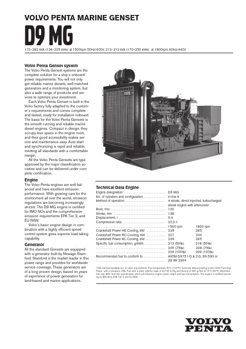
VOLVO PENTA MARINE GENSETD9 mG170–282 kVA (136–225 kWe) at 1500rpm 50Hz/400V, 213–313 kVA (170–250 kWe) at 1800rpm 60Hz/440VVolvo Penta Genset systemThe Volvo Penta Genset systems are thecomplete solution for a ship’s onboardpower requirements. Y ou will not onlyget reliable marine diesels, well-matchedgenerators and a monitoring system, butalso a wide range of products and ser-vices to optimize your investment.Each Volvo Penta Genset is built in theVolvo factory fully adapted to the custom-er’s requirements and comes completeand tested, ready for installation onboard.The basis for the Volvo Penta Gensets isthe smooth running and reliable marinediesel engines. Compact in design, theyoccupy less space in the engine room,and their good accessibility makes ser-vice and maintenance easy. Auto-startand synchronizing is rapid and reliable,meeting all standards with a comfortablemargin.All the Volvo Penta Gensets are typeapproved by the major classification so-cieties and can be delivered under com-plete certification.EngineThe Volvo Penta engines are well bal-anced and have excellent emission performance. With growing care for the environment all over the world, emission regulations are becoming increasingly stricter. T he D9 MG engine is certified for IMO NOx and the comprehensive emission requirements EPA Tier 2, and EU IWW.Volvo’s basic engine design in com-bination with a highly efficient speed control system gives superior load taking capability.GeneratorAll the standard Gensets are equipped w ith a generator built by Newage Stam-ford. Stamford is the market leader in this power range and provides for worldwide service coverage. These generators are of a long proven design, based on years of experience of power generation for land-based and marine applications.Technical Data EngineEngine designation......................... D9 MGNo. of cylinders and configuration ............. in-line 6Method of operation........................ 4-stroke, direct-injected, turbocharged. . . . . . . . . . . . . . . . . . . . . . . . . . . . . . . . . . . . . . . . . . diesel engine with aftercoolerBore, mm (120)Stroke, mm (138)Displacement, l ............................ 9.4Compression ratio .......................... 20.2:1. . . . . . . . . . . . . . . . . . . . . . . . . . . . . . . . . . . . . . . . . . 1500 rpm 1800 rpm Crankshaft Power HE Cooling, kW ........... 239 265Crankshaft Power RC Cooling, kW ........... 227 244Crankshaft Power KC Cooling, kW ............ 239 265Specific fuel consumption, g/kWh ............. 213 (50%) 218 (50%). . . . . . . . . . . . . . . . . . . . . . . . . . . . . . . . . . . . . . . . . . 205 (75%) 208 (75%). . . . . . . . . . . . . . . . . . . . . . . . . . . . . . . . . . . . . . . . . . 204 (100%) 206 (100%) Recommended fuel to conform to ............. ASTM-D975 1-D & 2-D, EN 590 or. . . . . . . . . . . . . . . . . . . . . . . . . . . . . . . . . . . . . . . . . . JIS KK 220410% overload available acc. to class requirements. Fuel temperature 40°C (104°F). Technical data according to ISO 3046 Fuel Stop Power with a tolerance ±4%. Fuel with a lower calorific value of 42700 kJ/kg and density of 840 g/liter at 15°C (60°F). Merchant fuel may differ from this specification which will influence engine power output and fuel consumption. The engine is certified accord-ing to IMO NOx, EPA Tier 2 and EU IWW.D9 MGTechnical descriptionComplete Genset– High system efficiency as a result of sys-tem optimization of the complete Genset – All used components of highest quality from well reputed suppliers– Reinforced set dimensioned for high output and low sound level– Mono-block engine/generator rigidly mounted on a common bed frame– Engine directly coupled to generator via a flexplate– Flexible mountings including welding plates mounted under the frame Engine and block– Cylinder block and cylinder head made of cast iron– One piece cylinder head– Replaceable wet cylinder liners and valve seats/guides– Drop forged crankshaft with induction hardened bearing surfaces and fillets with seven main bearings– Four valve per cylinder layout with over-head camshaft– Each cylinder features cross-flow inlet and exhaust ducts– Gallery oil cooled forged aluminum pis-tons, three piston rings (keystone top ring)– Senders for oil pressure (after filter), oil temp, oil pressure piston cooling, oil level, fuel pressure, freshwater pres-sure, exhaust temp, crankcase pressure, speed crank and cam, boost pressure/ temp, seawater pressure (HE), coolant level, coolant temp, water in fuel (not classifiable)Lubrication system– Freshwater-cooled oil cooler integrated in cylinder block– Twin full flow oil filter of spin-on type and single by-pass filterFuel system– Electronic Unit Injectors– Gear-driven fuel pump, driven by timing gear– Electronically controlled injection timing – 5-hole high pressure injector nozzles– Single engine-mounted fine fuel filter of spin-on type, with water separator and water in fuel sensor Turbocharger– Dry twin entry turbochargerHeat Exchanger cooled system (HE)– For seawater- and central-cooledGensets– Engine-mounted tubular heat exchangerwith expansion tank– Belt-driven centrifugal fresh water pump– Gear-driven rubber impeller raw waterpumpRadiator cooled system (RC)– For air-cooled Gensets– V-belt-driven radiator fan– Belt-driven centrifugal fresh water pump– Expansion tank mounted on radiator– Air to air CAC (Charge Air Cooler)Keel cooled system (KC)– 2-circuit cooling system– Belt-driven centrifugal fresh water pumpin HT circuit– Engine mounted expansion tank in HTcircuit– Gear driven rubber impeller fresh waterpump in CAC L T circuitGenerator– 4-pole, brushless, AC marine generator– Temperature rise class F– Tropical insulation class H– Stator winding as standard with short2/3 pitch winding, ideal for non-linearload (thyristor load)– Automatic Voltage Regulator (AVR) foraccurate voltage regulation– Permanent magnet mounted on generatorfor independent power supply to AVR– Single bearing generator as standard– Voltage available range up to 690V– IP23 enclosure as standard– Anti condensation heatingControl System– MCC a flexible and expandable controland monitoring system for classifiedinstallations. Incl. separate safety shut-down system– Meets classification requirements of sepa-rate shutdown and monitoring system– Easy to interface with leading suppliersof ship control systems– Possibility to connect relays for remotecontrol functions (potential free contacts)– Classifiable by all major classificationsocietiesOptional equipmentEngine– Twin engine-mounted fine fuel filter ofspin-on type with change over valve– Twin fuel pre-filters/water separatorwith change over valve– Flexible exhaust compensator– Cooling water connection bellows– Electrical, air or hydraulic starting sys-tems in various combinations– Raw water pressure indication (only incombination with raw water pump)– Exhaust temperature indication– Engine heater 2000WGenerator– Air inlet filters according to IP23– Air inlet louvres/filters according toIP44– Parallel equipment mounted in genera-tor– Thermistors (1 or 2 per phase) mount-ed in generator for temperature mea-surement of windings in generator– PT100 elements (1 or 2 per phase)mounted in generator for temperaturemeasurement of windings in generator– Double bearing generator (on request)– PT100 elements mounted in generatorbearings for temperature measurementMiscellaneous– Dry exhaust silencer with or withoutspark arrestor– 80A alternator with integrated chargingsensor– Basic toolkit– Spare parts according to classificationrecommendationsContact your local Volvo Penta dealer for further information.Not all models, standard equipment and accessories are avail-able in all countries. All specifications are subject to changewithout notice.The Genset illustrated may not be entirely identical to pro-duction standard Gensets.Technical Data HE GensetPower output at 1500 rpm 50H/400V, kVA (kWe)D9 MG / HCM434C-1 .........................210 (168)D9 MG / HCM434D-1 .........................230 (184)D9 MG / HCM434E-1.........................275 (220)D9 MG / HCM434F-1 .........................282 (225)Power output at 1800 rpm 60Hz/440V, kVA (kWe)D9 MG / UCM274H-1 .........................213 (170)D9 MG / HCM434C-1 .........................245 (196)D9 MG / HCM434D-1 .........................270 (216)D9 MG / HCM434E-1.........................313 (250)10% overload available according to class requirements. Fuel temperature 40°C (104°F). Techni-cal data according to ISO 3046 Fuel Stop Power and ISO 8665. Fuel with a lower calorific value of 42700 kJ/kg and density of 840 g/liter at 15°C (60°F). Merchant fuel may differ from this specifi-cation which will influence engine power output and fuel consumption.D9 MGTechnical Data RC GensetPower output at 1500 rpm 50Hz/400V, kVA (kWe)D9 MG / UCM274H-1 .........................170 (136)D9 MG / HCM434C-1 .........................210 (168)D9 MG / HCM434D-1 .........................230 (184)D9 MG / HCM434E-1.........................268 (214)Power output at 1800 rpm 60Hz/440V, kVA (kWe)D9 MG / UCM274H-1 .........................213 (170)D9 MG / HCM434C-1 .........................245 (196)D9 MG / HCM434D-1 .........................270 (216)D9 MG / HCM434E-1.........................288 (230)10% overload available according to class requirements. Fuel temperature 40°C (104°F). Techni-cal data according to ISO 3046 Fuel Stop Power and ISO 8665. Fuel with a lower calorific value of 42700 kJ/kg and density of 840 g/liter at 15°C (60°F). Merchant fuel may differ from this specifi-cation which will influence engine power output and fuel consumption.Dimensions L x W x H 1/H 2 (mm), not for installationD9 MG / UCM274H-1 ...........2492 x 1161 x 1712/1919D9 MG / HCM434C-1 ...........2660 x 1161 x 1712/1919D9 MG / HCM434D-1 ...........2660 x 1161 x 1712/1919D9 MG / HCM434E-1...........2660 x 1161 x 1712/1919D9 MG / HCM434F-1 ...........2750 x 1161 x 1712/1919Weight, kgD9 MG / UCM274H-1 .............................2260D9 MG / HCM434C-1 .............................2480D9 MG / HCM434D-1 .............................2570 D9 MG / HCM434E-1.............................2655D9 MG / HCM434F-1 .. (2790)H 1 = Height including exhaust compensator H 2 = Total genset height including control boxDimensions L x W x H 1/H 2 (mm), not for installationD9 MG / UCM274H-1 ...........2801 x 1165 x 1712/1919D9 MG / HCM434C-1 ...........2969 x 1165 x 1712/1919D9 MG / HCM434D-1 ...........2969 x 1165 x 1712/1919D9 MG / HCM434E-1...........2969 x 1165 x 1712/1919 Weight, kgD9 MG / UCM274H-1 .............................2210D9 MG / HCM434C-1 .............................2430D9 MG / HCM434D-1 .............................2520D9 MG / HCM434E-1.. (2605)H 1 = Height including exhaust compensator H 2= Total genset height including control boxD9 MGTechnical Data KC GensetPower output at 1500 rpm 50Hz/400V, kVA (kWe)D9 MG / HCM434C-1 .........................210 (168)D9 MG / HCM434D-1 .........................230 (184)D9 MG / HCM434E-1.........................275 (220)D9 MG / HCM434F-1 .........................282 (225)Power output at 1800 rpm 60Hz/440V, kVA (kWe)D9 MG / UCM274H-1 .........................213 (170)D9 MG / HCM434C-1 .........................245 (196)D9 MG / HCM434D-1 .........................270 (216)D9 MG / HCM434E-1.........................313 (250)10% overload available according to class requirements. Fuel temperature 40°C (104°F). Techni-cal data according to ISO 3046 Fuel Stop Power and ISO 8665. Fuel with a lower calorific value of 42700 kJ/kg and density of 840 g/liter at 15°C (60°F). Merchant fuel may differ from this specifi-cation which will influence engine power output and fuel consumption.Dimensions L x W x H 1/H 2 (mm), not for installationD9 MG / UCM274H-1 ...........2492 x 1161 x 1712/1919D9 MG / HCM434C-1 ...........2660 x 1161 x 1712/1919D9 MG / HCM434D-1 ...........2660 x 1161 x 1712/1919D9 MG / HCM434E-1...........2660 x 1161 x 1712/1919D9 MG / HCM434F-1 ...........2750 x 1161 x 1712/1919Weight, kgD9 MG / UCM274H-1 .............................2160D9 MG / HCM434C-1 .............................2380D9 MG / HCM434D-1 .............................2470 D9 MG / HCM434E-1.............................2555D9 MG / HCM434F-1 .. (2690)H 1 = Height including exhaust compensator H 2 = Total genset height including control boxAB Volvo PentaSE-405 08 Göteborg, Sweden7744615 E n g l i s h 05-2012. © 2012 A B V o l v o P e n t a .。
拖拉机常用词翻译

拖拉机常用词翻译1,2,3 speed PTO 1,2,3速动力输出2WD two wheel drive 两轮驱动3-point hitch 三点悬挂4 ultra-slow speed 4个超低速档4WD four wheel drive 四轮驱动540E (540 ECO)经济模式的540转动力输出Accelerator control lever 手油门手柄accelerator pedal 油门踏板accessory 附件adaptor 适配器adhere 粘附adhesive 粘合剂adjustable 可调的agribusiness 农业综合企业ail filter 空滤器air cooling 分冷的air inlet [intake] manifold 进气歧管air manifold 空气歧管align 使成一线alternator 发电机ambient temperature 温度ammeter电流表anticlockwise 逆时针anti-freeze 防冻液armature 电枢armrest 扶手assembly 装配Auxiliary control valve lever 多路控制手柄auxiliary socket 辅助套筒Axle casing桥外壳back hoe 后挖掘机backlash 间隙backrest 靠背backup 候补的Bale 打包baler 打包机,压捆机band 带子,组合barometer,air gauge气压表basic gearbox 基本(型)变速箱battery terminal电瓶极柱battery 电瓶battery 电瓶,蓄电池bearing 轴承bevel gear pair 锥齿轮副bleed 排空气blinker lamp 信号灯block-type synchromesh mechanism 滑块式同步器blown fuse 保险丝断bolt flange 有凸缘的螺栓bolts and nuts 螺钉和螺母bond 粘结(剂)bonnet 机罩boost charge 快充bore 缸径bore 孔,腔, 内腔bottom plow 铧式犁box blade 箱式平地机bracket 支架brake pedal 制动踏板broad caster撒种机,播种机built-in .内置的, 固定的, 嵌入的bulb 灯泡bush insulation 绝缘衬套bushing 衬套butt 粗大一端cable 电缆calcium chloride solution 氯化钙溶液cam 凸轮camshaft 凸轮轴capacity 容量,能力carbon 碳caution 警告Cement floor 水泥地面centrifugal pump 离心泵cetane 十六烷chassis 底盘chattering (机器)咯咯作响chisel plow 錾式犁circuit 回路circumference 周围clamp 夹具clamp 夹子clayey 粘土的clevis pin 叉杆销clip 夹子clockwise 顺时针clutch cover 离合器盖clutch disc boss 离合器摩擦片花键毂clutch disc 摩擦片clutch liner 离合器片clutch pedal 离合器踏板clutch release bearing 离合器分离轴承clutch 离合器cold starting device 冷启动装置collar 轴环combine instrument 组合仪表combine 组合combustion 燃烧compact tractor 紧凑拖拉机Compatibility 兼容性component 部件compress 压缩compression ratio 压缩比condenser 冷凝器cone-shape 锥形conical 锥形的connecting rod 连杆constant mesh transmission 啮合套换挡变速箱,常啮合式变速箱contact 联系coolant temperature guage 冷却液温度表coolant 冷却液coupling 连接盘,联合器crack 裂缝crank 有毛病的, 不正常的;曲柄crankshaft case 曲轴箱crankshaft 曲轴Creeper lever 爬行档手柄creeper 爬行档crimp 卷曲cultivate 培养,耕作cultivator 中耕机cushion 软垫cylinder block 机体cylinder head cove 缸头罩盖cylinder head 气缸盖damping 阻尼Dashboard 仪表板data 数据dealer 经销商dealership 商品经销特许权; 商品特许经销商Decal 贴签defective 故障的deflection 偏斜, 偏转, 偏差deflector 反射器[板], 反射镜Delivery 传输deluxe seat 豪华座椅demo 演示demonstrate 示范, 证明, 论证depress 压下detach 分开, 分离detergent 清洁剂diaphragm spring 膜片弹簧Diesel Engine 柴油机Differential lock switch 差速锁开关differential lock 差速锁diffirential差速器dimension 尺寸dipped headlight,low beam近光灯dipstick 量油计Direction indicator light 转向灯disc brake盘式制动disc-harrow 圆盘耙displacement 排量distilled water 蒸馏水distributor 批发商distributor分配器;分配装置Double action balanced steering cylinder 双作用平衡式转向油缸double thermostat 双节温器double-disk clutch with mechanical PTO 带机械式动力输出的双片离合器down silencer 下行排气管drag link 转向纵拉杆drag 牵引; 拖沓; 拖延; 迟缓的行动drain plug 放油塞draught angle牵引角drawbar 拖车,牵引钩dry disc brake 干式盘式制动dual clutch 双作用离合器dual strobe light 双过滤灯dumping angle 倾翻角durability 耐久dynamic 动力的ECU Environmental Control Unit 环境控制装置electro-hydraulic control 电液操纵electrolyte 电解液eliminate 排除engine block 发动机体Engine coolant temperature gauge 发动机水温表engine model 发动机型号Engine RPM and PTO RPM indicator 发动机和动力输出转速表engine type 发动机型式engine 发动机equivalent 相等的escutcheon 铭牌Essential 本质,实质establish 建立evacuator 抽空装置evaporate 蒸发exaggeration 夸大exclusively 专有地execute 执行,实施exhaust manifold 排气支管exhaust tappet gap. cold engine排气门间隙(冷态)exhaust valve 排气门explosive 易爆炸的exposure 暴露fan with 6 blades. Diameter 340 六片叶风扇。
长大后我想造火箭作文

长大后我想造火箭作文英文回答:I have always been fascinated by the vast expanse of space and the mysteries it holds. Growing up, I dreamed of becoming an astronaut and exploring the unknown realms beyond our planet. But as I grew older, I realized that my true passion lay in the engineering behind space exploration. I wanted to be the one designing and building the rockets that would carry us into the stars.The path to becoming a rocket scientist was not easy. It required years of rigorous study in science, technology, engineering, and mathematics. But with each challenge I faced, my determination grew stronger. I spent countless hours studying the laws of physics, thermodynamics, and fluid dynamics. I immersed myself in the works of great minds like Wernher von Braun and Sergei Korolev, learning from their triumphs and failures.As I delved deeper into the world of rocketry, I discovered the incredible complexity and sophistication involved in these machines. From the design of the combustion chamber to the optimization of the propulsion system, every aspect of a rocket required a deep understanding of engineering principles. But it was this very complexity that ignited my passion even further.I knew that becoming a rocket scientist would require more than just technical knowledge. It would also demand creativity, innovation, and a relentless pursuit of excellence. I joined a team of fellow students who shared my passion for space exploration, and together we embarked on ambitious projects to design and build our own rockets.Through countless iterations and failures, we learned the invaluable lessons that come from hands-on experience. We tested different fuel mixtures, experimented with different nozzle designs, and pushed the boundaries of our knowledge. With each setback, we grew stronger and more determined to overcome the challenges that lay ahead.As my undergraduate career drew to a close, I secured an internship at a prestigious aerospace company where I had the opportunity to work alongside experienced engineers on cutting-edge rocketry projects. This experience was transformative, providing me with invaluable insights into the practical aspects of rocket design and development.Upon graduating with honors in aerospace engineering, I received multiple job offers from leading companies in the industry. I ultimately accepted a position as a research engineer at a private space exploration company where I am now involved in the development of next-generation rockets.My journey to becoming a rocket scientist has beenfilled with challenges, but also with immense joy and satisfaction. It is a career that allows me to combine my passion for space exploration with my love for engineering. As I look up at the stars, I know that I am contributing,in my own small way, to the advancement of human knowledge and the exploration of the final frontier.中文回答:长大后,我想成为一名火箭科学家,探索宇宙中那些神秘未知的领域。
变透平效率有机朗肯循环工质筛选及多目标优化
变透平效率有机朗肯循环工质筛选及多目标优化韩中合;梅中恺;李鹏【摘要】To harness heat of 523.15 K high temperature flue gas, pentane, hexane, heptane, cyclohexane, MM (hexamethyldisiloxane), benzene and toluene were selected as working fluid candidates. With selection of one-dimensional radial-inflow turbine efficiency prediction model to replace constant turbine efficiency model, and net power output and exergy efficiency as target functions, organic Rankine cycle (ORC) system was simulated for multiple output variables by using non-dominated sorting genetic algorithm (NSGA-Ⅱ). Optimal solution of each working fluid was determined from Pareto frontiers by ideal point estimation. The results show a strong correlation between turbine efficiency and volumetric flow ratio (VFR) of working fluids in a way that turbine efficiency curve trends oppositely to VFR curve. At fixed heat source conditions, benzene is the optimal working fluid whereas toluene and cyclohexane are sub-optimal. Exergy efficiency accelerates in a downward trend at evaporation temperature above 400 K, but net power output slows down in a rise trend at evaporation temperature above 410 K. Optimization with constant turbine efficiency model somewhat affects screening results of optimal parameters and best working fluid, which are deviated from actual outcomes. However, optimization with variable turbine efficiency model can reduce such error and results are much closer to engineering practice.%针对523.15 K的中高温余热烟气热源,选取戊烷、己烷、庚烷、环己烷、MM(六甲基二硅氧烷)、苯和甲苯为候选工质,引入一维向心透平效率预测模型取代固定透平效率,以?效率和系统净功为目标函数,基于NSGA-Ⅱ算法对 ORC系统进行多目标求解,采用理想点辅助法对各工质 Pareto 前沿进行决策寻优.得出以下结论:工质的透平效率与透平等熵膨胀比(VFR)存在较强的相关性,透平效率曲线与VFR曲线的变化趋势相反;在给定热源条件下,苯是最优工质,甲苯和环己烷是次优工质;当蒸发温度超过400 K时,?效率下降趋势加快,当蒸发温度超过410 K时,系统净功上升趋势放缓;定透平效率寻优会对最佳参数与最优工质筛选结果造成一定影响,与实际存在偏差;变透平效率寻优可以减少误差,更接近工程实际.【期刊名称】《化工学报》【年(卷),期】2018(069)006【总页数】9页(P2603-2611)【关键词】有机朗肯循环;多目标优化;一维向心透平效率预测模型;热力学;经济;透平等熵膨胀比【作者】韩中合;梅中恺;李鹏【作者单位】华北电力大学电站设备状态监测与控制教育部重点实验室,河北保定071003;华北电力大学电站设备状态监测与控制教育部重点实验室,河北保定071003;华北电力大学电站设备状态监测与控制教育部重点实验室,河北保定071003【正文语种】中文【中图分类】TK123引言随着能源需求的迅速增长,低品质能源的利用成为当前研究的热点[1-8]。
第三代流式细胞分选仪及96孔板分选单个细胞的方法及参数优化
第三代流式细胞分选仪及96孔板分选单个细胞的方法及参数优化闵智慧;程韵枫【摘要】目的:用第三代流式细胞分选仪比较不同直径喷嘴分选的单细胞的得率及细胞活性,进一步完善单细胞微孔板分选的参数设置及条件优化。
方法:用FACSAria Ⅲ流式细胞分选仪及96孔板对Raji细胞、A549、DT 40、RAW 264.7细胞系进行单细胞分选,分别采用70μm 、100μm和130μm喷嘴分选,比较分选后单细胞得率及克隆形成率。
结果:在单细胞分选模式下,用3种不同直径喷嘴及96孔板分选后的单细胞得率为86.55%~93.44%,即96孔板有单细胞的孔数为84~92孔;分选后的单个细胞培养7 d后,经70μm 、100μm 和130μm喷嘴分选的单细胞克隆孔数分别为31~52孔、49~70孔、58~78孔。
结论:进行单细胞微孔板分选时,在精确调节及优化实验参数的前提下,为了保证单细胞的活性,应优先选择100μm或130μm喷嘴。
%Objective:To compare the sorted single cell rate and cell viability with different diameters of nozzles by the third‐generation flow cytometry sorter FACS Aria Ⅲ so as to further improve the optimization of parameter settings and conditions for single‐cell microplate sorting .Methods :Single‐cell sorting of four different types of cell lines‐Raji cells ,A549 , DT40 ,RAW 264 .7 cell line‐was done on FACSAria Ⅲ flow cytometry sorter and 96‐well microplate .70 μm ,100 μm and 130 μm diameter nozzles were adopted respectively ,an d the sorted single cell rate and the cell colony‐forming rate were counted .Results:In the single‐cell sorting mode ,the percentages of sorted single cell with three nozzles were from 86 .55% to 93 .44% ,which meant that the holenumbers with single cell in the 96‐well micorplate were from 84 to92 .After 7‐day culture , Single cell clone hole numbers sorted by 70 μm , 100 μm and 130 μm diameter nozzles were 31‐52 , 49‐70 and 58‐78 , respectively .Conclusions : In single cell sorting with the microplate and under the premise of accurate adjustment and optimization of parameters ,100 μm or 130 μm nozzles should be given preference for single cell activity .【期刊名称】《中国临床医学》【年(卷),期】2016(023)006【总页数】5页(P846-850)【关键词】单细胞分选;流式细胞分选仪;96孔板;喷嘴;液滴延迟【作者】闵智慧;程韵枫【作者单位】复旦大学附属中山医院临床研究院实验研究中心,上海 200032; 复旦大学附属中山医院青浦分院实验研究中心,上海 201700; 上海市器官移植重点实验室,上海 200032;复旦大学附属中山医院临床研究院实验研究中心,上海200032; 复旦大学附属中山医院血液科,上海 200032; 复旦大学附属中山医院青浦分院实验研究中心,上海 201700; 复旦大学附属中山医院青浦分院血液科,上海 201700; 上海市器官移植重点实验室,上海 200032【正文语种】中文【中图分类】Q2-33随着分选型流式细胞仪功能的不断完善,其在单细胞分选相关研究中的应用越来越广泛,尤其广泛应用于细胞个体差异研究、单细胞基因测序、转录组学研究[1],以及代谢物转运途径、肿瘤细胞免疫应答机制、富集异质性微生物群落研究等方面[2-5]。
- 1、下载文档前请自行甄别文档内容的完整性,平台不提供额外的编辑、内容补充、找答案等附加服务。
- 2、"仅部分预览"的文档,不可在线预览部分如存在完整性等问题,可反馈申请退款(可完整预览的文档不适用该条件!)。
- 3、如文档侵犯您的权益,请联系客服反馈,我们会尽快为您处理(人工客服工作时间:9:00-18:30)。
1 bar (Exp.) 10 bar (Exp.) 20 bar (Exp.) 30 bar (Exp.) 40 bar (Exp.)
Penetration Length [mm]
70 60 50 40 30 20 10 0 0 100 200 300 400 500 600 700 800 900 1000 1100 1200 1300
Variation of injection rate according to different nozzle types
Engine Research Dep’t
6/31
Experiment Results(2)
Spray visualization images
Ambient pressure
Meshes for piston movement and combustion analysis
10/31
Engine Research Dep’t
Computational Simulation(3)
Wave breakup model [Reitz (1987)]
Rate of change of drop radius due to drop breakup Model constant C2 with variation of ambient pressure
tan
=
Spray Angle [deg]
θ
2
4π A
2
ρg ρf
22
⋅ f (T )
Fit: f(T)= 0.1+1 .2T0 .5 fit_0 .30mm fit_0 .32mm fit_0 .34mm
20
18
ρ f ⎛ Re f ⎜ T≡ ρ g ⎜ We f ⎝
⎞ ⎟ , A = 3 + 0.278 lo ⎟ do ⎠
5/31
Photograph of high pressure chamber and fuel injection pump
Experiment Results(1)
Injection pressure & rate
1600 1400 1200 70
Injection Pressure [bar]
area) (0.7068) (0.6433) (0.8042) (0.8171)
400 200 0 -10 0 10 20 30 40
10 0 -10 -10 -5 0 5 10 15 20 25 30 35 40
Crank Angle [degCA]
Crank Angle [degCA]
Variation of injection pump pressure according to different nozzle types
2005 AVL Korea AST User Conference
Optimization of Fuel Injection Nozzle for the Reduction of NOx Emission in Medium-Speed Marine Diesel Engine
Wook-Hyeon Yoon, Byong-Seok Kim, Sung-Hyup Ryu, Ki-Doo Kim and Ji-Soo Ha
Engine Research Dep’t
Photograph of our own developed Hyundai HiMSEN engine
2/31
Study Processing
EXPERIMENT
Rig Test Engine Test
Injection rate Injection Pressure Spray Angle Spray Penetration Cylinder Pressure Heat Release Rate NOx & Soot
Experiment
Time [µsec]
Comparison of simulated and measured spray tip penetration with variation of ambient gas density Engine Research Dep’t
Nozzle type Chamber pressure Cam-shaft speed Load
Measurement parameters Injection Pressure Injection Rate Needle Lift Spray Angle Spray Tip Penetration
Objectives
Optimization of combustion and reduction of NOx emission in Hyundai HiMSEN engines Experiments on the fuel spray behavior Evaluation of the numerical results with experimental ones Effect of fuel injection nozzle geometry on NOx & fuel consumption
Engine Research Dep’t
3/31
Experimental Setup(1)
Rig test of fuel injection system
Test conditions
Injection system Cam-driven fuel injection 28X10, 30X10 32X08, 34X09 1 to 50 bar 360, 450 rpm 50, 75, 100 %
Breakup time
(r ≤ a)
a ⎛ ρf τ = C2 ⎜ w ⎜ ρg ⎝
⎞ ⎟ ⎟ ⎠
0.5
20 30 40
Breakup lift time constant, C2 Life time of each drop Affects spray tip penetration Engine Research Dep’t
Sequential images of transient spray from the bottom-view
Байду номын сангаас
Engine Research Dep’t
7/31
Experiment Results(3)
Correlation of spray angle[Reitz and Bracco (1979)]
COMPUTATION
3-D Flow Simulation 3-D Combustion Simulation
Spray Velocity Spray Penetration Spray Droplet Size Cylinder Pressure Heat Release Rate NOx Emission
1000 800 600
Injection rate (Kg/mm3)
Noz zle type (total sec tion area) 30X10 (0.7068) 32X08 (0.6433) 32X10 (0.8042) 34X09 (0.8171)
60 50 40 30 20
Nozzle type (total s ection 30X10 32X08 32X10 34X09
Ambient Pressure [bar] 1 10 Density [kg/m3] 1.18 11.86 23.76 35.67 47.57 Spray angle [deg] 14.48 16.91 18.38 19.50 20.44 C2 2 20 30 50 70
da a−r =− dt τ
Computational Simulation(1)
FIRE v8.34 software
Prediction of heat release rate and NOx formation Validation of spray breakup model Adjustment of breakup model constants Comparison of the numerical results on spray tip penetration with experimental data in the high pressure chamber Validation of combustion model Adjustment of model constants for auto-ignition, combustion rate, and NOx formation rate Comparison of the numerical results on the cylinder pressure and NOx production with experimental data of HiMSEN engine
Engine Research Dep’t
9/31
Computational Simulation(2)
Mesh generation.
Total no. of cells : 88,320 Total no. of cells : 100,000 ~ 200,000
Mesh for the calculation of spray behavior
Engine Research Department, Hyundai Industrial Research Institute Hyundai Heavy Industries Co., Ltd. 2005. 10. 13
Engine Research Department