南泽硬件使用说明书
NSR641RF-D02厂用变备自投装置技术及使用说明书v3.11

4.1 测控功能 ........................................................ 20 4.2 通信功能 ........................................................ 23 4.3 对时功能 ........................................................ 24 4.4 自检功能 ........................................................ 25 4.5 信息记录功能 .................................................... 25 4.6 录波功能 ........................................................ 26 4.7 定值管理功能 .................................................... 27 4.8 保护出口继电器配置功能 .......................................... 27 4.9 打印功能 ........................................................ 28 4.10 口令管理功能 ................................................... 29 4.11 版本信息功能 ................................................... 29
NNSS22001166接口4线电阻触摸屏控制器用户手册说明书

N S2016用户手册V1.0深圳市纳芯威科技有限公司2009年7月目录1 功能说明 (4)2 主要特性 (4)3 应用领域 (4)4 典型应用电路 (4)5 极限参数 (5)5.1 电气特性 (6)6 芯片管脚描述 (8)6.1 管脚分配图 (8)6.2 引脚功能描述 (8)7 NS2016典型参考特性 (9)8 工作原理 (11)8.1 基本原理描述 (11)8.2 模拟输入特性 (11)8.3 内部参考电压 (12)8.4 单端工作模式 (12)8.5 差分工作模式 (13)8.6 触摸屏应用建议 (13)8.7 温度测量 (14)8.8 电池电压测量 (15)8.9 压力测量 (15)9 数字接口 (16)9.1 写命令 (16)9.2 读命令 (17)9.3 高速模式 (18)9.4 数字时序 (18)9.5 数据格式 (20)9.6 笔中断输出 (20)10 应用注意事项 (21)11 芯片封装物理尺寸 (22)11.1 TSSOP-16封装 (22)图目录图1 NS2016典型应用电路 (4)图2 TSSOP-16封装管脚分配图 (8)图3 NS2016模拟输入简图 (11)图4 内部电压源示意图 (12)图5 单端模式工作示意图(C3=0,Y方向驱动开关闭合,XP作为模拟输入) (13)图6 差分参考源工作模式简图(C3=1,Y方向驱动开关闭合,XP作为模拟输入) (13)图7 温度测量功能示意图 (14)图8 电池电压测量功能模块图 (15)图9 压力测量模块图 (16)图10 I2C接口写命令时序图 (16)图11 I2C接口读命令时序图 (17)图12 NS2016数字接口时序图 (18)图13 理想情况输入电压和输出编码对应关系 (20)图14 PENIRQ功能模块图 (20)图15 TSSOP-16封装尺寸 (22)表目录表1 芯片极限参数表 (5)表2 NS2016电气特性表 (6)表3 ADC输入信号配置 (11)表4 地址字节 (16)表5 命令字节 (17)表6 PD1、PD0控制位 (17)表7 时序规范说明 (18)1功能说明NS2016是一款4线制电阻式触摸屏控制器,内含12位分辨率A/D转换器。
测深仪SDE-18+操作手册

II
第一章 测深仪的工作原理
第一章 测深仪的工作原理
§1.1 测深仪简介
在发明回声测深仪之前,人们探测水底地貌一直采用绳索铅锤的办法, 在测量船航行过程中,每隔一定时间间隔,测量员用系有铅锤的绳索放到水 底,通过量测绳索上的标志得到水的深度,来记录一个水深点,由于用这种 办法测量的水底地貌不连续(有不能人为控制的测量间隔),人们很难发现水 中的航行障碍物。发明回声测深仪后,使测量船所经之处的测量船航迹线, 由不连续的测量数据变成连续的模拟水底信号线,线上的各点水深可以任意 选取。测深仪换能器发射的超声波束具有一定的散射角(开角),这是由换能 器的性能所决定的也就是说,测深仪记录纸上每个回波信号记录的水深为每 个波束笼罩水底范围内的最浅值,人们为了提高测深精度,不断的缩小超声 波波束的开角,现在测量使用的测深仪换能器波束角一般在 3°-10°之间。
1-2
《测深仪操作手册》
第一章 测深仪的工作原理
满足工程中的需要。 南方测深仪为全中文数字化工程型测深仪,其显示完全中文化,清晰可
辨,重量轻,携带方便,电源使用灵活,能单独使用内置或外置电池工作, 也可以同时工作,输出水深数据用标准 RS232 接口协议进行传输,南方测深 仪可以满足大部分水上工程用户的需要。
南泽硬件使用说明书

D-Day南泽说明书北京奥运鸟巢停车系统唯一指定品牌感应式智能停车场管理系统硬件使用说明书深圳市南泽电子有限公司目录一、施工安装使用说明 (2)1.设备摆放安装尺寸图 (2)2.线圈安装施工布线 (3)3.系统工程布线图 (4)二、系统联网说明 (6)三、主要部分功能及接线说明 (6)1.系统控控制器………………………………………………………………………………5-7 2.通讯转换器………………………………………………………………………………8-9 3.环路检测器………………………………………………………………………………9-10一、施工安装使用说明土建安装:1.用户根据现场实际情况,规划好设备摆放位置,并将设备定位,可参考如下《设备摆放尺寸图》2. 用混凝土浇铸一高10-20CM的防水防撞的安全岛,并根据<系统布线图>把线管及线材埋好。
线圈施工:如图,一般标准情况道闸地感线圈施工在闸杆下方离300-500mm位置,近距离有车读卡/取卡线圈,在入口控制机的正面前方的位置,用混泥土切割机切出一760mmX1830mm带倒角的矩形切槽,再切一引线切槽至设备内,切槽宽度20mm,深度为40 mm左右。
将地感线嵌入矩形切槽5-8匝,地感线圈双绞后引线引至设备内接到车辆检测器上,再用水泥、沥青或环氧树脂封住锯缝。
温馨提示:地感线圈要保证无破损、无漏电、线无接头、不能与大面积金属靠近,与相邻地感线圈电感量留有差异(面积不同或匝数不同)以免发生电磁共振而导致检测失效。
特殊情况通道地感线圈布线尺寸不同,如6米通道、对开通道、远距离有车读卡等。
A-A204设备安装:参考如下设备底座安装尺寸图将设备摆放在水泥岛上,或其它适合位置。
并根据设备的孔位,选好适合的膨胀螺丝将设备固定紧。
单位:mmA-A《图1》DD-168A票箱安装底座图《图2》DD-700票箱安装底座图工程布线:1. 布线时请注意信号线请使用RVVP2x0.5mm或RVVP4x0.5mm屏蔽线. 并将屏蔽层按图良好接地,以提高抗雷击抗干扰性能。
南方S750手持GPS硬件操作及关键设置
第一章产品简介SOUTH S750是广州南方测绘仪器有限公司第一代GPS手持数据采集系统,其采用国际知名品牌的GPS定位模块及主板,性能卓越的掌上型电脑(PDA),将其融合为具有人体工程学设计的一体化三防主机,能满足移动数据采集在恶劣环境中所需的高性能,坚固和耐久的综合要求。
S750主机使用WindowsCE 5.0操作系统,包含了易于用户掌握使用的,人性化的软件组件。
同时该产品还可以扩展为其他用途,为第三方软件提供良好的数据输出工作。
1.1 产品指标(1)系统:●操作系统:Microsoft Windows Embedded CE 5.0●处理器:Intel PXA-270 520MHz XScale, 32 bit RISC CPU●内存储器:128MB RAM /128MB M-System闪存、SD记忆卡扩展槽(2)媒体:●NVIDIA GoForce4000 多媒体芯片●集成扬声器、麦克风,支持录音及回放●480x640分辨率,3.6英寸Full VGA彩色液晶显示器,TFT触摸屏●全数字键盘录入,软键盘字符录入(3)数据通讯:●完整的RS232●USB On-The-Go (USB 1.1)●802.11b/g无线LAN●蓝牙1.2、Class II标准●内置GPRS/GSM通讯模块(选配)(4)GPS指标:●接收机:L1,C/A码,带载波相位平滑●通道:单频,12通道,并行跟踪(双通道SBAS跟踪)●重捕获时间:<1s●数据更新率:1Hz,可设置(最大20Hz)●冷启动:30s~45s●EVEREST多路径抑制技术(5)定位精度(典型值):●实时差分改正:亚米级(CEP)(外部源修正或SBAS)●后差分处理:亚米级(CEP)●静态:水平5mm+1ppm,高程10mm+1ppm(典型值要求最少能锁定5颗卫星,PDOP小于6,SNR最小值为39dBHz,且有合理的多路径条件等)(6)协议:●完全支持SBAS(MSAS\WAAS\EGNOS)●数据I/O,NMEA-0183(GGA、ZDA、GLL、RMC、GSA、GSV、VTG),TSIP●修正量I/O协议:RTCM2.3(1、3、9)(7)物理:●尺寸:284mm x 95mm x 37mm●重量:0.73kg(带电池)(8)电气:●电池:3.7V,2700mAh,可拆卸●在线充电:AC100-240~,0.5A,50-60Hz(9)工作环境:●湿度:5%~95% RH 非凝结状态●操作温度:-20摄氏度到+50摄氏度(-4华氏度到122华氏度)●存储温度:-40摄氏度到+60摄氏度(-40华氏度到140华氏度)●防水防尘等级IP65,完全保护从各个方向的冲水及扬尘,防震动及撞击1.2 产品特点介绍1、专业的GPS模块国际专业品牌测量型GPS天线及定位主板,采用最新的ASIC芯片和COAST专利算法,比导航型主板搜星更迅速稳定,定位更精确可靠。
上南zsne~2411智能温控器说明书
上南zsne~2411智能温控器说明书
1、温度显示数码管
在正常情况下,该4位数码管显示实际检测到的温度数值,此时对应
的菜单代码为L00。
2、菜单显示数码管
在正常情况下,该3位数码管显示L00,代表意思是:上面4位数码管
显示的是温度(以数值形式显示)或则显示“Erro”(故障)。
3、返回按键(BACK):
在参数设后,按下该键,3位菜单数码管将返回到正常状态“L00”;当4位数码管显示“Erro”时,在排除外部所有电气故障时,按下该键将一键清除内部故障锁存,控制器进入正常工作模式。
4、向上按键(UP):
在设定参数值时,该键用来增加数值;在进行菜单翻页时,该键用来上翻。
5、向下按键(DOWN):
在设定参数时,该键用来减少数值;在进行菜单翻页时,该键用来下翻。
6、确认键(ENTER):
在参数设定后,按下该键用来确认参数更改输入。
CZe6600手持终端说明书

CZe6600手持终端说明书南京才哲电气自动化有限公司目录1.操作说明 (3)1.1.开关机 (3)1.1.1.开机 (3)1.1.2.关机 (3)1.2.键盘说明 (3)1.3.功能菜单 (4)1.4.通讯设置 (7)1.4.1.通讯工具 (7)1.4.2.下载应用程序 (7)1.4.3.显示/删除抄表机内应用文件 (8)1.4.4.下载开机画面 (8)1.4.5.上传数据 (9)1.4.6.系统时间 (9)2.注意事项及问题解答 (9)1.操作说明1.1.开关机1.1.1.开机按手持终端【电源】键,听到“嘀”一声后,屏幕显示如图:或进入上次关机前的状态界面。
按任意键进入应用程序;按【菜单F2】进入系统菜单。
1.1.2.关机抄表机有三个途径可以关机:键盘关机、定时关机、掉电关机。
■键盘关机:使用【电源】键。
■定时关机(自动关机):是指在抄表机使用过程中,规定时间内没有任何按键操作时系统会自动关机,但进行数据通信时系统不会自动关机。
■掉电关机:是指在电池电量不足的时候,抄表机会自动关闭机器。
如果掉电时抄表机正在操作液晶屏幕,再次开机后屏幕可能会有些花点,这属于正常现象,屏幕再次刷新后即可消除花点。
1.2.键盘说明键盘的数量为20个独立健,其中包括【电源】【背光】组合键。
编号按键功能1电源开/关机2背光开/关液晶背光3F1打印打印票据4F2菜单菜单,复位5上翻上翻屏幕数据信息6下翻下翻屏幕数据信息7清除清除输入内容,退出8确认确认输入内容90-9数字键10.小数点11+功能键1.3.功能菜单抄表机的系统向用户提供了一个全菜单化的界面,能让用户对整个系统进行设置和控制。
【1】系统通讯用通讯电缆将上位计算机与手持终端正确连接后进行通讯传输。
若通讯方式是串口,则显示串口通讯。
【2】系统信息〔1〕机器信息〔2〕文件信息可以查看机器内的应用程序和数据库名称,以及文件数量和机器剩余的可用空间大小。
〔3〕系统时间此菜单显示抄表机系统时间信息;机内有一颗备份电池,它为时间提供电源,外面的充电电池掉电情况下,可以保持时间正常继续运行。
HELP2000G_X_说明书_国内中文_国内标准版_X_R1.00_(X)

HELP2000G稳定控制装置测试装置说明书HELP2000G稳定控制装置测试装置 前言使用产品前,请仔细阅读本章节!本章叙述了使用产品前的安全预防建议。
在安装和使用时, 本章内容必须全部阅读且充分理解。
忽略说明书中相关警示说明,因不当操作造成的任何损害,本公司不承担相应负责。
在对本装置做任何操作前,相关专业人员必须仔细阅读本说明书,熟悉操作相关内容。
l操作指导及警告本手册中将会用到以下指示标记和标准定义:危险! 意味着如果安全预防措施被忽视,则会导致人员死亡,严重的人身伤害,或严重的设备损坏。
警告! 意味着如果安全预防措施被忽视,则可能导致人员死亡,严重的人身伤害,或严重的设备损坏。
警示! 意味着如果安全预防措施被忽视,则可能导致轻微的人身伤害或设备损坏。
本条特别适用于对装置的损坏及可能对被保护设备的损坏。
警告!为增强或修改现有功能,装置的软硬件均可能升级,请确认此版本使用手册和您购买的产品相 兼容。
警告!电气设备在运行时,这些装置的某些部件可能带有高压。
不正确的操作可能导致严重的人身伤 害或设备损坏。
只有具备资质的合格专业工作人员才允许对装置或在装置临近工作。
工作人员需熟知本手册中 所提到的注意事项和工作流程,以及安全规定。
特别注意,一些通用的工作于高压带电设备的工作规则必须遵守。
如果不遵守可能导致严重的 人身伤亡或设备损坏。
危险!在一次系统带电运行时,绝对不允许将与装置连接的电流互感器二次开路。
该回路开路可能会 产生极端危险的高压。
HELP2000G 稳定控制装置测试装置警告!l 曝露端子在装置带电时不要触碰曝露的端子等,因为可能会产生危险的高电压。
l 残余电压在装置电源关闭后,直流回路中仍然可能存在危险的电压。
这些电压需在数秒钟后才会消失。
警示!l 接地装置的接地端子必须可靠接地。
l 运行环境该装置只允许运行在技术参数所规定的大气环境中,而且运行环境不能存在不正常的震动。
l 额定值在接入交流电压电流回路或直流电源回路时,请确认他们符合装置的额定参数。
Lenze93ES简易操作

为控制板提供外部24V电源(I > 1A) -
93ES系列
简易操作
6、让电机转起来
① 完成控制器的主电源接线、电机接线、反馈接线、控制端子接线(采 用内部供电方式),给变频器上电; 红色 LED 指示灯闪烁
② 控制端子位置
- 控制器使能 - E1 ~ E3、 E5 - E4 - 电位器 低电平 ; 低电平 ; 高电平 ; 输出电压调到最低电压
2 3
未激活
= +
10k
4 7 X6
4 7 X6
实际速度 内部电源
7 62 63 2mA 2mA -10V..+10V U -10V..+10V U
GND1
7
GND1 2mA 2mA -10V..+10V U -10V..+ 63
+10V
为了让X6/63输出+10V电压需设定: C0005 = XX1X ; 例如C0005 = 1010 内部电源供电下的速度控制方式
= 2.5V
电机端编码器接 头管脚号
最大电缆长度 50 m
RefSIN SIN RefCOS COS Vcc GND -RS485 +RS485 +KTY -KTY
93XX
9 1 2 3 4 5 6 7 11 12
X8 9 针D型 1 接头
2 3 4 5 6 7 8 9
KTY
–编码器的供电电压可以 在 5~8V间调整 – 采用双绞屏蔽线. – 两端屏蔽线均须接PE地.
X8 9 针D型 1 接头
2 3 4 5 6 7 8 9
KTY
–编码器的供电电压可以在 5~8V间调整 – 采用双绞屏蔽线. – 两端屏蔽线均须接PE地.
PNOZX10使用说明

PNOZX10使用说明
1.硬件连接:
在使用PNOZX10之前,首先要确保正确连接设备。
将音频设备(如麦克风、乐器等)插入PNOZX10的输入通道,然后将输出通道连接到功放、音箱或电脑等设备上。
2.控制界面:
3.基本设置:
在开始使用PNOZX10之前,需要进行一些基本设置。
通过菜单界面可以设置采样率、位深、输入输出通道等参数,确保符合项目需求。
4.录制功能:
5.混音功能:
6.后期制作:
7.存储和导出:
8.软件升级:
9.常见问题解答:
总结:
PNOZX10是一款功能强大的音频处理平台,适用于音频录制、混音和后期制作等多个领域。
通过正确的硬件连接和基本设置,用户可以轻松进行高质量的音频录制。
同时,PNOZX10的混音和后期制作功能可以帮助用
户进一步提升音频的质量和效果。
通过存储和导出功能,用户可以方便地保存和分享音频数据。
NEXO NX-241使用说明
快速入门本部分总结了那些未曾阅读本说明书的人经常提问的问题。
由于NX241 TD控制器的设计非常易于操作,所以用户应该很快会使用本控制器。
但无论如何请花一些时间阅读本说明书。
深入了NX241 TD控制器将有利于你发挥整个系统的性能。
请在使用本控制器前确保输入电源的电压正确。
警告:必须严格按所提供的信息使用功放。
在使用系统前,必须按“菜单2.6功放增益”和“菜单2.7功放功率”的要求设置系统。
不按此要求设置系统或不正确连接“反馈线”将会使NEXO的保修单失效。
复位同时按下按钮A、B和SWAP可以使本控制器复位,而不需要关闭电源。
选择扬声器组打开电源以后或在设备复位的时候,同时按下按钮A和B可以进入系统修改菜单。
按下按钮A和B直至所有的LED等熄灭,这时可以自由选择扬声器组。
使用旋钮,可以浏览里面的设置,按下“ENTER”会把设置载入。
选择扬声器设置可以在菜单3.0里选择扬声器组的设置(例如,你不用改变功放到扬声器的接线)。
浏览菜单在控制器的显示屏幕上“功能”前的数字就是菜单编号。
要变换菜单编号的第一个号码(主菜单编号)必须按下按钮A,变换第二个号码(子菜单编号)必须按钮B。
旋动旋钮或者按下SWAP(交换)按钮可以选择设置。
回复到默认值在菜单2.5里,可以把所有的设置恢复到厂家的默认值(除了所输入的功放资料)(菜单2.6和2.7).自动储存为了防止有可能出现的电源,控制器在你上次改变设置后每2分钟自动保存当前的设置。
电源恢复后,设置会自动恢复。
控制器支持的预先设置列表(LOAD1_80)在印刷本说明书的时候,控制器的软件版本为LOAD1-80,它支持以下的设置。
Alpha扬声器组Alpha E扬声器组PS扬声器组配置NX241音频的通道为24比特,而中心计算器为48比特,运算能力为1亿个指令每秒。
其性能如下:◆2个模拟输入(平衡),24比特模/数转换器◆4个模拟输出(平衡),24比特模/数转换器◆4个感应输入(不平衡),18比特模/数转换器可以有如下的配置:◆立体声无源模式,带(或者不带)单声道超低频(2个独立的无源扬声器)◆立体声无源模式,带立体声超低频以及单声道无源模式,带2个超低频扬声器◆有源4路模式以及有源3路(单声道)模式◆有源3路+在输入B上的辅助超低频模式◆立体声有源2路模式均衡和滤波器超低频和甚高频(VHF)滤波控制器使用高通和低通滤波器,以过滤掉那些有可能损害TD控制器和功放性能的频率成分。
Sophos XG系列硬件设备操作说明书

Operating InstructionsXG 105(w)/115(w)/125(w)/135(w) Rev. 3/XG 106(w) Rev.1ForewordWe are pleased to welcome you as a new customer of our Sophos XG appliances.To install and configure the hardware appliance you can use the following documents:ÌHardware Quick Start Guide: Connection to thesystem peripherals in a few stepsÌOperating Instructions: Notes on the security andcommissioning of the hardware applianceÌAdministration Guide: Installing and configuring the software applianceThe Hardware Quick Start Guide and the Safety Instructions are also deliveredin printed form together with the hardware appliance. The instructions must be read carefully prior to using the hardware and should be kept in a safe place.You may download all user manuals and additional documentation from the support webpage at: /supportSecurity SymbolsThe following symbol and its meaning appears in the Hardware Quick Start Guide, Safety Instructions and in these Operating Instructions.Caution and Important Note. If these notes are not correctly observed:ÌThis is dangerous to life and the environmentÌThe appliance may be damagedÌThe functions of the appliance will be no longer guaranteedÌSophos shall not be liable for damages arising from afailure to comply with the Safety InstructionsDesigned UseThe hardware appliances are developed for use in networks.The XG 105(w)/106(w)/115(w)/125(w)/135(w) models may be operated asa standalone appliance. The hardware appliance can be used in commercial, industrial and residential environments.The XG 105(w)/106(w)/115(w)/125(w)/135(w) models belong to the appliance group B.The hardware appliance must be installed pursuant to the current installation notes. Otherwise failure-free and safe operation cannot be guaranteed. The EU declaration of conformity is available at the following address:Sophos Technology GmbHAmalienbadstr. 41/Bau 5276227 KarlsruheGermanyCE Labeling, FCC and ApprovalsThe XG 105(w)/106(w)/115(w)/125(w)/135(w) appliances comply with CB, CE, FCC Class B, ISED, VCCI, RCM, UL, CCC, and BIS.Important Note: For computer systems to remain CE and FCC compliant, only CE and FCC compliant parts may be used. Maintaining CE and FCC compliance also requires proper cable and cabling techniques.Operating Elements and ConnectionsXG 105(w)/115(w)*(Rev. 3)/XG 106(w) Rev.1Status LEDs (w-model has additional Wi-Fi LED)1 x COM (RJ45)2 x USB 2.0 1 x Micro USB4 x GbE copper port1 x GbE SFP (shared)1 x HDMI Power Supply Connector for optional 2nd redundant power supply2 x external antenna(XG 125w and XG 135w only)XG 125(w)/135(w)*(Rev. 3)Status LEDs (w-model has additional Wi-Fi LED)1 x COM(RJ45)3 x external antenna(XG 125w andXG 135w only)2 x USB 2.08 x GbE copper port Power Supply Optional 2nd redundant power supply1 x MicroUSB1 x HDMI Expansion bay (shown with optionalmodule incl. 2 antennas)1 x GbE SFP * The displayed front images are of the XG 115 and 135 device. The displayed back images are of the XG 115w device and the XG 135w. Devices may vary slightly.LED StatusSpeed (Right LED)Amber On The Ethernet port is operating at 1,000 Mbps. Green On The Ethernet port is operating at 100 Mbps.Off The Ethernet port is operating at 10 Mbps.Speed(Right LED)Amber On The Ethernet port is operating at 1,000 MbpsPutting into OperationCaution: Risk of explosion if battery is replaced by an incorrect type. Dispose of used batteries according to the instructions.Scope of SupplyThe supplied parts are indicated in the Hardware Quick Start Guide. Mounting InstructionsThe XG 105(w)/106(w)/115(w)/125(w)/135(w) appliances can be placed on a stable horizontal surface or can be mounted to a rack or you can hang it on the wall by using the optionally available rackmount kit.Warnings and PrecautionsThe appliance can be operated safely if you observe the following notes and the notes on the appliance itself.Rack PrecautionsÌEnsure that the leveling jacks on the bottom of the rack are fullyextended to the floor with the full weight of the rack resting on them.ÌIn single rack installation, stabilizers should be attached to the rack.ÌIn multiple rack installations, the racks should be coupled together.ÌAlways make sure the rack is stable beforeextending a component from the rack.ÌYou should extend only one component at a time—extending two ormore simultaneously may cause the rack to become unstable.General Server PrecautionsÌReview the electrical and general safety precautions that camewith the components you are adding to your appliance.ÌDetermine the placement of each component inthe rack before you install the rails.ÌInstall the heaviest server components on thebottom of the rack first, and then work up.ÌAllow the hot plug hard drives and power supplymodules to cool before touching them.ÌAlways keep the rack‘s front door, all panels and server componentsclosed when not servicing to maintain proper cooling.Rack Mounting ConsiderationsÌAmbient operating temperature: If installed in a closed or multi-unit rack assembly, the ambient operating temperature of the rack environmentmay be greater than the ambient temperature of the room. Therefore,you should install the equipment in an environment compatiblewith the manufacturer’s maximum rated ambient temperature.ÌReduced airflow: Equipment should be mounted intoa rack with sufficient airflow to allow cooling.ÌMechanical loading: Equipment should be mounted into a rack so that a hazardous condition does not arise due to uneven mechanical loading.ÌCircuit overloading: Consideration should be given to the connectionof the equipment to the power supply circuitry and the effect that anypossible overloading of circuits might have on overcurrent protectionand power supply wiring. Appropriate consideration of equipmentnameplate ratings should be used when addressing this concern.ÌReliable ground: Reliable grounding must be maintained at all times.To ensure this, the rack itself should be grounded. Particular attentionshould be given to power supply connections other than the directconnections to the branch circuit (i.e., the use of power strips, etc.).Connection and ConfigurationHow to connect the appliance is described in the Hardware Quick Start Guide. For configuration you can follow the initial setup wizard described in the WebAdmin Quick Start Guide or cancel it and perform a manual setup (see the Sophos XG Firewall Administrator Guide).SFP PortThe XG1xx rev.3 and XG 106(w) rev.1 models provide a SFP port allowing you to either insert a SFP Mini-GBIC (transceiver) to connect to a 1 GbE fiber or copper cable or to insert a VDSL2 SFP modem to directly connect to a VDSL line (via a RJ11 cable).These modules are not delivered with the appliance but available through your Sophos partner.Please note that there are different Mini-GBIC module types. The required type is determined by the existing network. The following SFP GBIC module types may be used:SFP:1000 Base-TIEEE 802.3 - 1 Gbit/s via Ethernet cable. An Ethernet cable category 5 covers a maximum distance about 100 meters.1000 Base-SXIEEE 802.3 - 1 Gbit/s via fiberglass. Multi-mode fiberglass cables (MMF) cover a distance of 200 m to 550 m.1000 Base-LXIEEE 802.3 - 1 Gbit/s via fiberglass. Here, exclusively singlemode-fiber glass is used. This transmission option covers approximately 10 km.Expansion ModulesThe XG 125(w)/135(w) support an additional expansion module allowing you to insert an optional 3G/4G or Wireless module (on XG 135w only). These modules are not delivered with the appliance but available through your Sophos partner. Please note that there are different 3G/4G modules available depending on the region you want to operate it in Americas/EMEA and APAC.Please see table below for further details.For installing the module please read the mounting instructions which are shipped with each module.Serial ConsoleYou can connect a serial console to either of the COM ports of the Sophos XG hardware appliances. You can use, for instance, the Hyperterminal terminal program which is included with most versions of Microsoft Windows to log on to the appliance console. Use an RJ45 to DB9 adapter cable or the provided USB cable to connect the console to your hardware appliance.The required connection settings are:ÌBits per second: 38,400ÌData bits: 8ÌParity: N (none)ÌStop bits: 1Access via the serial console is activated by default on ttyS1. The connections of the appliances and the respective functionality are listed in chapter “Operating Elements and Connections.”United Kingdom and Worldwide Sales Tel: +44 (0)8447 671131Email:****************North American SalesToll Free: 1-866-866-2802Email:******************Australia and New Zealand SalesTel: +61 2 9409 9100Email:****************.auAsia SalesTel: +65 62244168Email:********************© Copyright 2018. Sophos Ltd. All rights reserved.Registered in England and Wales No. 2096520, The Pentagon, Abingdon Science Park, Abingdon, OX14 3YP, UK Sophos is the registered trademark of Sophos Ltd. All other product and company names mentioned are trademarks or registered trademarks of their respective owners.。
南方s750说明书

S750 G2 使用手册
5.1.3 坐标系统设置....................................................................... 35 5.1.4 实时设置 .............................................................................. 36 5.2 调试网络 ......................................... 40 5.3 创建文件,进行作业................................ 41 5.4 坐标转换 ......................................... 48
2.2 开机使用 .......................................... 7 2.2.1 开机 ........................................................................................ 7 2.2.2 关机 ........................................................................................ 8
2.3 与电脑的连接....................................... 8 2.4 校正触摸屏......................................... 8 2.5 重新启动 S750 G2 主机............................... 8
1.1 产品指标 .......................................... 1 1.2 产品特点介绍....................................... 3 1.3 配置单 ............................................ 4
南方测绘灵锐S86说明书

第五章 S86GPS内业数据传输............................................................. 38
5.1 数据传输(安装部分)............................................................. 38 5.2 S86 助手的使用 ......................................................................... 39 5.3 S86 的注册和升级 ..................................................................... 41
灵锐 S86RTK 测量方案在先有的基础上,作业方式更加简洁 灵动。是又一款稳定、高效的测量产品。S86 测量系统产品在功 能、性能、速度和功耗等方面满足了用户更高的要求。
Pepperl+Fuchs UC4000-L2-E6-V15 超声传感器产品说明书
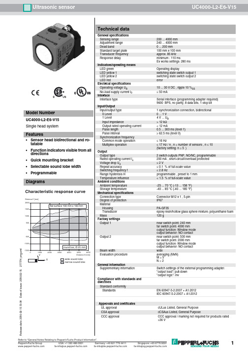
Ultrasonic sensor UC4000-L2-E6-V15R e l e a s e d a t e : 2016-02-15 13:04D a t e o f i s s u e : 2016-02-15277774_e n g .x m lDimensionsElectrical ConnectionPinoutLED yeLED gn LED ye LED gn 37M 12 x 12867402030405.5ø 5.54660T 1T 2o u t 1p w r /o u t 240Synchronization Switch output 1Switch output 215234L+L-134521 B N2 WH3 BU4 BK5 GYWire colors in accordance with EN 60947-5-2(brown)(white)(blue)(black)(gray)R e l e a s e d a t e : 2016-02-15 13:04D a t e o f i s s u e : 2016-02-15277774_e n g .x m lDescription of Sensor FunctionsProgramming procedureThe sensor features two outputs with two programmable switch points, each (for a total of 4). Programming the switch points and the operating mode can be done in two different ways:-via the sensor’s programming buttons-via the serial interface, which requires an external interface adapterThe procedure for programming via the sensor's programming buttons is described below. For programming using the serial interface, please refer to the software manual.Switch points and operating modes of each output can be programmed independently without influencing each other.Note:-Programming is enabled for 5 minutes after power-on. After 5 minutes without programming activity the programming feature will be locked.-During any programming step it is possible to leave the programming routine without changing the sensor settings by pressing the currently used programming button for 10 s.Programming the Switch PointsNotes:-The description below leads you through programming output 1’s switch points. The procedure for output 2 is exactly the same with the only difference, being to use the Programming Button T2.-If the red LED flashes during the programming procedure, it indicates uncertain target detection. In this case, please correct the target alignment until the yellow LED flashes. The new settings will only be stored in the sensor’s memory if the yellow LED flashes.Programming the Near Switch Point1.Place the target at the desired near switch point position2.Press Programming Button T1 for 2s (corresponding yellow LED flashes)3.Press Programming Button T1 briefly (green LED flashes three times for confirmation). The sensor returns to normal operation.Programming of the Far Switch Point1.Place the target at the desired far switch point position2.Press Programming Button T1 for 2s (corresponding yellow LED flashes)3.Press Programming Button T1 for 2s (green LED flashes three times for confirmation). The sensor returns to normal operation.Programming Modes of OperationNote:The description below leads you through programming of the modes of operation for output 1. The procedure for output 2 is exactly the same with the only difference,being to use Programming Button T2.The sensor provides a three step routine to program the modes of operation. In this routine you can program:1.Output function 2.Output behavior 3.Beam widthProgramming the modes is carried out sequentially. To toggle from one mode to the next, press the Programming button for 2s.Press Programming Button T1 for 5s to enter the operating modes programming routine.Programming the output function1.The green LED flashes. The number of flashes indicates the current output function:single flash: Switch point output function double flash: Window output function triple flash: Hysteresis output function.2.Press Programming Button T1 briefly to toggle sequentially through these output functions and select the desired mode.3.Press Programming Button T1 for 2s to save and enter the programming routine for output behavior Programming the output behavior1.The yellow LED flashes. The number of flashes indicates the current output behavior:single flash: Normally Open (NO)double flash: Normally Closed (NC).2.Press Programming Button T1 briefly to toggle sequentially through these output behaviors and select the desired mode.3.Press Programming Button T1 for 2s to save and enter the programming routine for beam width.Programming the beam width1.The red LED flashes. The number of flashes indicates the current beam width setting:single flash: narrow double flash: medium triple flash: wide.Programming adapter PACTware 4.X FDT FrameworkUltraschall-Sensoren DTMDTM devices for communication with cube style and UMC... sensors V15-G-2M-PVCFemale cordset, M12, 5-pin, PVC cable Microsoft .NETR e l e a s e d a t e : 2016-02-15 13:04D a t e o f i s s u e : 2016-02-15277774_e n g .x m l2.Press Programming Button T1 briefly to toggle sequentially through these beam shapes.3.Press Programming Button T1 for 2s to save and exit the operating modes programming routine.Note:Independently programming the beam width for each individual output is not possible. The last programmed beam width is valid for both outputs. It doesn’t matter which Pro-gramming Button is used.Reset Sensor to Factory SettingsThe sensor has a feature to reset to factory settings 1.Disconnect the sensor from power supply2.Press and hold one of the Programming Buttons T1 or T23.Connect Sensor to power supply (red and yellow LED flash simultaneously for 5s then green and yellow LED flash simultaneously)4.Release Programming ButtonThe sensor now operates with default factory settings.Factory settingsSee technical data.DisplayThe sensor is provided with LEDs to indicate various conditions.*) off if yellow LED out2 is onSynchronizationThis sensor features a synchronization input for suppressing ultrasonic mutual interference ("cross talk"). If this input is not connected, the sensor will operate freewheeling using internally generated clock pulses. It can be synchronized by applying an external square wave or by means of appropriate programming via the serial interface. Each falling edge of the synchronization pulse triggers transmission of a single ultrasonic pulse. If the synchronization signal remains low for ≥ 1 second, the sensor will revert to normal operating mode. Normal operating mode can also be activated by opening the signal connection to the synchronization input.(See note below)If the synchronization input goes to a high level for > 1 second, the sensor will switch to standby mode, indicated by the green LED. In this mode, the output(s) will remain in the last valid output state. When using the external synchronization feature, please refer to the software description.Note:If the option for synchronization is not used, the synchronization input has to be connected to ground (0V) or the sensor has to be operated via a V1 cordset (4-pin).The synchronization function cannot be activated during programming mode and vice versa.The following synchronization modes are possible:1.Several sensors (max. number see technical data) can be synchronized together by interconnecting their respective synchronization inputs. In this case, each sensor alternately transmits ultrasonic pulses in a self multiplexing mode. No two sensors will transmit pulses at the same time. (See note below)2.Several sensors (max. number see technical data) can be synchronized together by interconnecting their respective synchronization inputs. Due to programming via the sensors interface one sensor acts as a master device, all the others as slave devices. (see description of the interface) In this master / slave mode the sensors are triggered in parallel and are synchronized by a common synchronization pulse, provided by the master device.3.Multiple sensors can be controlled by the same external synchronization signal. In this mode the sensors are triggered in parallel and are synchronized by a common external synchronization pulse. All sensors must be parameterized for external synchronization by means of the sensor interface. See software description.4. A separate synchronization pulse can be sent to each individual sensor. In this mode the sensors operate in external multiplex mode. (See note below). All sensors must be parameterized for external synchronization by means of the sensor interface. See software description.5. A high level (+U B ) or a low level (-U B )on the synchronization input switches the sensor to standby mode if it is parameterized for external synchronization.Note:Sensor response times will increase proportionally to the number of sensors that are in the synchronization string. This is a result of the multiplexing of the ultrasonic transmit and receive signal and the resulting increase in the measurement cycle time.Note:The sensors syncronization input delivers an output current in case of low level and burdens with its input impedance in case of high level. Please pay attention that the syn-chronizing device needs to have that driver capability:driver current against +U B ≥ n * high-level/input impedance (n = number of sensors to be synchronized)driver current against 0V ≥ n * output current (n = number of sensors to be synchronized).Green LEDYellow LED out1 / out2Red LED During Normal operation Proper operationInterference (e.g. compressed air)On *)Off Switching state output 1 / output 2remains in previous stateOff On During Switch Point Programming Object detected No object detectedConfirmation after Programming Programming failed warningOff OffTriple flashingOff Flashing Off Off Off Off Flashing OffTriple flashing During Sensor Mode Programming Programming the output function Programming the output behaviour Programming the beam widthFlashing Off OffOff Flashing OffOff Off Flashing。
南方7527PSION手簿产品手册说明

按下ALT键,然后用光标点击任务栏,选择“Properties”(属性),然后选择你需要显示在任务栏的项。
例如,若是需要在任务栏显示时钟,在“show clock”(显示时钟)处选中即可,如此任务栏中就会显示时刻信息,如图。
开始菜单:
当触摸屏失效时,利用System Tray(系统托盘)功能能够用键盘将光标移动到任务栏各图标上,再查看相关信息,如平安水平及电池电量信息。
第三章
手簿正面
手簿反面
键区
电池
PSION手簿利用的是标准的锂离子电池包,为了在拔取电池时保证手簿内的数据不丢失,手簿内置了备用的纽扣电池。
安装和拔取电池包
打开电池盖
1. 按后盖下方旋钮处的图标,把两边的旋钮旋至开锁状态。
2.移开盖子
安装电池
1.把充满电的电池放进电池槽内。
2.盖上电池后盖,把两边的旋钮旋相当锁状态。
WindowsMobile6 ProfessionalEdition (Phone Edition)
多媒体芯片
NVIDIA GoForce 4000多媒体处置器
实不时钟
在备用电池充满电后,能保留系统时钟数据和时刻至少3个月。
无线传输
集成蓝牙射频模块
蓝牙Class II标准:工作范围从5米到10米.
可选以下扩展模块:①(通过CF接口)
显示系统与内存信息,在内存选项卡,能够从头分派存储内存与程序内存。
能够直接连接到台式电脑
网络拨号连接显示手簿的网络配置窗口或是已经存在的网络设置将被执行。
短距离的无线蓝牙通信设施。
Suspend:相当于关闭手簿。
Warm Reset:热启动,已保留的数据和文件可不能丢失(未保留的数据将丢失)。
FKAttend_Manual

参考
USBReadAllEnrollDataFromFile_Color
USBWriteAllEnrollDataToFile_Color
USBGetOneEnrollData_Color, USBSetOneEnrollData_Color
USBGetOneEnrollDataWithString_Color, USBSetOneEnrollDataWithString_
2.1 机器连接与断开.................................................................... 8 2.1.1 ConnectComm............................................................................ 8 2.1.2 ConnectNet............................................................................. 8 2.1.3 ConnectUSB............................................................................. 9 2.1.4 DisConnect............................................................................. 9 2.1.5 ConnectGetIP........................................................................... 9
2009.12
- 1、下载文档前请自行甄别文档内容的完整性,平台不提供额外的编辑、内容补充、找答案等附加服务。
- 2、"仅部分预览"的文档,不可在线预览部分如存在完整性等问题,可反馈申请退款(可完整预览的文档不适用该条件!)。
- 3、如文档侵犯您的权益,请联系客服反馈,我们会尽快为您处理(人工客服工作时间:9:00-18:30)。
感应式智能停车场
管理系统
硬
件
使
用
说
明
书
深圳市南泽电子有限公司
目录
一、施工安装使用说明 (2)
1.设备摆放安装尺寸图 (2)
2.线圈安装施工布线 (3)
3.系统工程布线图 (4)
二、系统联网说明 (6)
三、主要部分功能及接线说明 (6)
1.系统控控制器………………………………………………………………………………5-7 2.通讯转换器………………………………………………………………………………8-9 3.环路检测器………………………………………………………………………………9-10
一、施工安装使用说明
土建安装:1.用户根据现场实际情况,规划好设备摆放位置,并将设备定位,可参
考如下《设备摆放尺寸图》
2. 用混凝土浇铸一高10-20CM的防水防撞的安全岛,并根据<系统布线
图>把线管及线材埋好。
线圈施工:如图,一般标准情况道闸地感线圈施工在闸杆下方离300-500mm位置,近距离有车读卡/取卡线圈,在入口控制机的正面前方的位置,用混泥土切割机切出一
760mmX1830mm带倒角的矩形切槽,再切一引线切槽至设备内,切槽宽度20mm,深度
为40 mm左右。
将地感线嵌入矩形切槽5-8匝,地感线圈双绞后引线引至设备内接到
车辆检测器上,再用水泥、沥青或环氧树脂封住锯缝。
温馨提示:地感线圈要保证无破损、无漏电、线无接头、不能与大面积金属靠近,与相邻地感线圈电感量留有差异(面积不同或匝数不同)以免发生电磁共振而导致检测失效。
特殊
情况通道地感线圈布线尺寸不同,如6米通道、对开通道、远距离有车读卡等。
A-A
20
4
设。
工程布线:1. 布线时请注意信号线请使用RVVP2x0.5mm或RVVP4x0.5mm屏蔽线. 并将屏蔽层按图良好接地,以提高抗雷击抗干扰性能。
强电
220V请使用3x4 m²电源线.. 多台电脑联网时(超过100米以上)请使用
光纤布线,这样数据传输速度更快。
2 避免干扰强电与弱电不可同管道,布线时线头最好预留,尽量避免接
头,焊点,保障线路通畅,简易维护工作.
3.220V电源可以就近取电,电源线应尽量打麻花,避免信号干扰,备
用线可根据实际情况进行预留。
二、系统联网说明
三、主要部分功能及接线说明●系统控制器
1.系统控制器接线图
2.控制器操作说明
①编程登入(Login)输
DD-266
“2”
7”
⑤删除感应卡(Del Card ) CLR
CLR
CLR
●通讯处理器
1.连接图
性能参数
)接口特性:接口兼容EIA/TIA的RS-232C、RS485/RS-422标准。
)电气接口:RS-232接口输入DB9母头连接器,RS-422/RS-485接口输出DB9母头的连接器。
)保护等级:RS-232接口+/-15KVESD保护,RS-422、RS-485接口每线600W的浪涌保护。
)隔离度:隔离电压2500Vrms 500DC连续专用DC/DC模块。
5)工作方式:导步半双工或异步全又工
6)信号指示:三个信号指示灯电源(PWR)、发送(TXD)、接收(RXD)
7)传输介质:双绞线或屏蔽线
8)传输速率:
115.2K BPS到300M
38.4K BPS到2.4KM
9600BPS到5KM
9)使用环境:-40℃到85℃,相对温度为5%到95%
10)传速距离:0-5000(115200bps-9600bps),建议,超过1000米超好使用光纤布线,传输速度更快。
2.RS-485/RS-422输出信号及接线端子引脚分配
DB9Male
(PIN)
输出信号RS232全双工接线RS-485半双工接线
1 T/R+ 发(A+)RS-485(A+)
2 T/R- 发(B-)RS-485(B-)
3 RXD+ 收(A+)空
4 RXD- 收(B-)空
5 GND 地线地线
6 VCC 电源10-30VDC输入
9VDC输出电源10-30VDC输入9VDC输出
7 N/A
8 N/A
9 N/A
3.计算机的配置推荐:
CPU ;Intel Pentium E2160
内存:金士顿(King ston)1G
硬盘::希捷/西部数据160G
显卡:七彩虹、华硕、双敏(除昂达),显内128M以上。
主板:华硕大915以上配置(一定不能是昂达)
串口
鼠标:双飞燕PS/2接口(非USB接口)
键盘:双飞燕、罗技PS/2接口
电源:大水牛,长城350W
电脑串口卡:配置电脑时自已驱动好
安装系统:、WINXP或WIN2000
●环路检测器
1. 概述:
DD-HLA系列智能车辆检测器主要用于车辆存在检测。
适用于停车场、公路收费及交通信号灯控制等。
该探测器为单通道探测器,即只能同时监测一个电感线圈,它具有两个继电器用以提供输出信号,客户可选择不同的输出信号用来控制机械驱动器、出卡设备或计算车辆。
2. 安装检测器:
车辆检测器必须装在离检测线圈尽可能近的、防水防潮的干燥环境里。
检测器能否良好工作在很大程度上取决于它所连接的检测线圈。
线圈的几个重要参数包括:线圈形状、大小、匝数、埋设方法等。
3. 连接:
4. 使用:
接线说明:
1)1、2脚位接入电源(220V AC)。
2)10、6、5脚位为K1输出继电器(分
别为常闭、动、常开)。
3)11、4、3脚位为K2输出继电器(分
别为常闭、动、常开)。
4)7、8脚位接检测线圈。
(9脚空)地
感
信
号
①接道闸控制器
地感信号
②或接发卡机信
号
③或接蓝牙主机
蓝牙主机设有车读卡接地感说明
①蓝牙主机设有车读卡拔码设置如下:
开关位序号 1
开关位名称车辆检测读卡开关
开关ON位对应功能有车辆检测读卡功能
开关OFF位对应功能无车辆检测读卡功能
车辆检测读卡开关,需要地感功能时将其拨至ON位,不需要时反之。
②蓝牙主机地感信号接口(VDSIN)接线方式
1)1拖1 接线方式:DG1 与GND2)1拖2 接线方式:DG1与GND一组,DG2与GND一组
打开电源后,检测器将自检。
自检程式约需3秒,当自检通过后绿色指示灯由闪烁变为熄灭。
在自检期间,检测线圈最好为空(不应有车停其上)。
车辆检测器自检成功后,当线圈上有车通过时,绿色指示灯亮且相应的输出继电器动作。
如果检测器没有反应,请调整面板的灵敏度设置开关。
5. 灵敏度调节:
灵敏度调节使用面板上部“Sens.”拨动开关,共有三档,“L”为最低,“H”为最高。
四、停车场收费管理系统安装注意事项
1.使用线材:
a:电源线采用3*1.5的电源线,线径不能选用过小!
b:信号通讯线请选用屏蔽效果好的屏蔽线,距离越远屏蔽效果要求越高,建议用达到128扁以上的屏蔽线。
C:联接摄象机请选用专业视频线:如:75-5 线。
D:计算机之间的网络请使用网线连接,如果距离太远既要用光纤联网,避免信号衰竭。
E:管材请根据工程现场情况和消防要求选pvc管或者铁管。
2.布线:
a:计算好管材数量,强电和弱电不可同管道,强电和信号线不能同管道。
B:布线时线头请尽量预留,尽量避免出现接头,焊点,保障线路通畅,简易维护工作。
C: 注意安装地感线圈,如果有多个线圈,线圈间距不要太小,要大于3m,从线圈到车辆检测器这段请进行双绞,一米要大于20绞;线圈附近不要靠近钢铁,电场,磁场;小心安装,不要磨破线圈的包皮。
避免对线圈工作造成影响。
D:接线时请按照安全规范,不要带电操作;细心接线,不要接错端口。
3.安装:
a.硬件安装时请注意防尘防雨,安装过程中不要通电,道闸安装时注意杆子不要被过往车辆撞损,完成杆子安装后把杆子升起来;如果杆子比较长或者是折叠臂时,要固定好膨胀螺丝后
在操作调试,避免杆子太重落下时设备倒下。
b.在计算机上完成软件安装,等待硬件通电调试。
4.调试:
a:请按照调试步骤:接通设备后,先拿附带的测试卡调试硬件设备;再连接上软件整个系统进行测试。
B:中间过程请参照说明书进行,不要让人随意拆卸设备,不要让人随意设置设备,因在有专门负责人情况下对照设备要求达到的性能逐条调试。
C:如果调试过程中有什么疑惑不明处,请及时与我方联系,共同解决出现问题。
D:调试完成后,请让整套设备处于工作状态,适当老化设备。
5.保养,培训:
a:对于硬件设备,平时请注意防水防尘,作好电路板的灰尘清理工作(主要用带有酒精的棉花团),定时检查线路,防止线路脱落引起系统故障和漏电现象。
;对于道闸请定时给转动部分添加润滑油。
延缓设备老化。
B:软件的备份定时执行,防止因计算机故障引起数据丢失;计算机整理和重装时也要事先做好备份。
C:培训操作人员,按照说明书操作系统,不要随意人为的改动设备设置。
