APX500音频分析仪使用简易图解
APX500音频分析仪使用简易图解
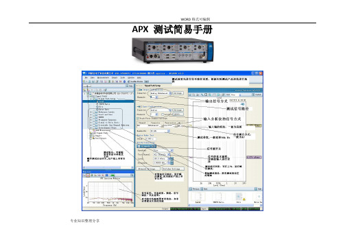
APX 测试简易手册专业知识整理分享信号路径的设置蓝牙播放器测试1.在信号源路径中选择bluetooth.2.点击settings 进行配对连接。
3.选择A2DP Source HSP4.点击Scan for devices 搜索被测产品5.点击pair 进行配对6.连接A2DP 协议7.开始测试相关测试项目专业知识整理分享蓝牙主机(Audio Gateway)的测试1.Input Configuraton 路径设置为bluetooth2.点击settings 进行配对连接。
3.选择A2DP link ( Hand-free 或者headset)4.点击Scan for devices 搜索被测产品5.点击pair 进行配对6.连接A2DP 协议7.开始测试相关测试项目专业知识整理分享功放测试1.根据实际接线,设置信号源的输出信号方式2.根据实际接线,设置分析仪的输入信号方式专业知识整理分享DVD、CD的测试1.信号源设为none2.分析仪接口设置与实际接线方式一致。
专业知识整理分享选择测试项目根据测试需求增加项目专业知识整理分享专业知识整理分享专业知识整理分享电平测试1.设置信号源输出波形2.设置信号源大小3.设置信号源频率4.打开信号源开关5.读取测量值专业知识整理分享失真测试1设置信号源输出波形,2设置信号源大小3设置信号源频率4打开信号源开关专业知识整理分享6读取测量值信噪比测试1设置信号源输出波形2设置信号源大小3设置信号源频率4打开信号源开关专业知识整理分享6读取测量值频率扫描测试1.设置信号源波形2.设置信号源大小3.设置信号源开始频率,结束频率,扫描点数4.设置滤波器专业知识整理分享5.点击Start 开始测试。
总谐波失真加噪声频率扫描测试1设置信号源波形2设置信号源大小3设置信号源开始频率,结束频率,扫描点数专业知识整理分享4设置滤波器5 点击Start 开始测试生成测试报告专业知识整理分享专业知识整理分享。
Tannoy iwSA 500 音频放大器说明书
2TANNOY iwSA 5002.0 WARNINGSBefore using your amplifier, be sure to carefully read the applicable items of these operating instructions and the safety suggestions.• Read these instructions.• Keep these instructions.• Heed all warnings.• Follow all instructions.• Do not use this apparatus near water.• Clean only with dry cloth.• Do not block any ventilation openings. Install in accordance with the manufacturers instructions.• Do not install near any heat sources such as radiators, heat registers, stoves, or other apparatus (including amplifiers) that produce heat.• Do not defeat the safety purpose of the polarized or grounding - type plug. A polarized plug has two blades with one wider thanthe other. A grounding type plug has two blades and a third grounding prong. The wide blade or the third prong are providedfor your safety. If the provided plug does not fit into your outlet, consult an electrician for replacement of the obsolete outlet.• Protect the power cord from being walked on or pinched particularly at plugs, convenience receptacles, and the point where they exit from the apparatus.• Only use attachments/accessories specified by the manufacturer.• Use only with the cart, stand, tripod, bracket, or table specified by the manufacturer, or sold with the apparatus. When a cart is used use caution when moving the cart/ apparatus combination to avoid injury from tip-over.• Unplug this apparatus during lightning storms or when unused for long periods of time.• Refer all servicing to qualified service personnel. Servicing is required when the apparatus has been damaged in any way suchas Power-supply cord or plug is damaged, liquid has been spilled or objects have fallen into the apparatus, the apparatus has been exposed to rain or moisture, does not operate normally, or has been dropped.• To completely disconnect this equipment from the mains, disconnect the power supply cord from the receptacle.• The mains plug of the power supply cord shall remain readily operable.• Do not remove top or bottom covers. Removal of the cover will expose hazardous voltages. There are no serviceable parts inside and removal may void the warranty.2.1 Important Safety Instructions2.2 WARNINGThe lightning flash with arrowhead symbol within an equilateral triangle is intended to alert the user to the presence of uninsulated “dangerous voltage” within the product’s enclosure that may be of sufficient magnitude to constitute a risk of electrical shock to persons.2.3 CAUTIONThe exclamation point within an equilateral triangle is intended to alert the user to the presence of important operating and maintenance (servicing) instructions in the literature accompanying the product.2.2 WARNINGTo reduce the risk of fire and electric shock, do not expose this apparatus to rain or moisture and objects filled with liquids, such as vases, should not be placed on the apparatus.3Thank you for selecting Tannoy developed by our dedicated team of design engineers, they are the choice of discriminating music and movie lovers the world over. Excellence is designed into our loudspeakers and electronics from the start. Careful selection of the very best components combined with strict quality control procedures during the production process ensures this level of excellence is maintained. We feel confident that you will enjoy your new Tannoy loudspeakers/electronics for many years to come.Please take time to read the rest of this owner’s guide before using your loudspeakers/electronics to gain maximum effect from their use. Once you have installed your new loudspeakers/electronics please complete and return the registration document – this does not limit your legal rights.CONTENTSINTRODUCTION3.0 APPROVALS2.0 WARNINGS2.1 Important Safety Instructions 2.2 WARNING 2.3 CAUTION7O W N E R ’S M A N U A LINTRODUCTIONMany in-wall and ceiling loudspeaker are designed simply to reproduce sound without any consideration for ultimate audio quality and vocal articulation. Not so with Tannoy installation products. Tannoy in-wall speaker systems are monitor quality speaker systems based on the company’s expertise in the manufacture of premium quality cabinet loudspeakers and studio monitors.The iwSA 500 amplifier was created specifically to maximize the inherent performance of your T annoy inwall subwoofer. By carefully matching the amplifier’s capabilities and performance criteria to the inwall subwoofer, Tannoy has enabled installers and end users to carefully tailor the performance to the job at hand.iwSA 50023446756.0 CONNECTIONS6.1 Input Connections 6.2 Connecting the Speaker 6.3 Cable Choice7.0 OPERATION7.1 Operation Precautions8.0 PROTECTION FEATURES8.1 Limiter Function9.0 MAINTENANCE 10.0 TROUBLESHOOTING 11.0 WARRANTY12.0 Technical Specifications iwSA 5008978882.4 User Responsibility 2.4.1 Speaker Damage 2.4.2 Radio Interference4.0 INTRODUCING THE iWSA 5004.1 Unpacking 4.2 Front Panel 4.3 Rear Panel5.0 INSTALLATION5.1 Mounting5.2 Operating Voltage43.0 APPROVALSThis equipment is tested and approved according to the Canadian Standards Association (CSA/C/US) and Federal Communications Commission (FCC).2.4 USER RESPONSIBILITY 2.4.1 Speaker DamageYour amplifier is very powerful and can be potentially dangerous to both, loudspeakers and humans alike. Many loudspeakers can be easily damaged or destroyed by overpowering, especially with the high power available. Always check the speakers’ continuous and peak power capabilities.Even is the amplifier’s front panel attenuators can be used to reduce the gain, it is still possible to reach full output power if the input signal level is high enough.TANNOY iwSA 5002.4.2 Radio InterferenceThis equipment has been tested and found to comply with the limits for a Class B digital device, pursuant to Part 15 of the FCC Rules. These limits are designed to provide reasonable protection against harmful interference from electrical equipment. This product uses radio frequency energy and if not used or installed in accordance with these operating instructions, may cause interference `in a particular installation.If this equipment does cause harmful interference to radio or television reception, which can be determined by turning the equipment on and off,the user is encouraged to try to correct the interference by one or more of the following measures:• Reorient or relocate the antenna.• Increase the separation between the equipment and receiver.• Connect the equipment into an outlet on a a circuit different from that to which the receiver is connected.• Consult the dealer or an experienced radio/TV technician for help.TANNOY iwSA 500iwSA 5007TANNOY iwSA 5006.3 Cable ChoiceAlways use the best quality of cable available within your budget. High quality audio signals passing from the amplifier to the loudspeaker are unusual in their demands on the cable. Wide dynamic range and frequency bandwidth information has to coexist with the ability to transmit peak currents of at least 10 Amps, without incurring any loss or signal impairment. This explains why the sound quality of the information reproduced by the loudspeakers is so dependant on the physical properties of the cables connecting them to the amplifier.Technically, we recommend two-core cable with cross section area not less than 1.5mm 2 (14 gauge) for cable runs of up to 3 metres. For longer lengths we would suggest that you use cable with a minimum cross sectional area of 2.5mm 2 (12 gauge).Keep the speaker cable leads as short as possible. Do not use shielded leads, such as microphone or guitar cable. Remember that the speaker cable robs the power of the amplifiers in two ways: by increasing the load impedance and by introducing resistive power losses.iwSA 5005.0 INSTALLATION The amplifier is two rack units high (2U) and will fit into a standard EIA 19” rack. Amplifiers should not be stacked directly on top of each other,we recommend a space at least 3” for the top and sides with 5” on the back . When shelf mounted the height of the supplied feet is adequate.5.1 MountingWARNING!A label just above the mains cable connector on the rear of the amplifier indicates the AC mains voltage for which the amplifier is wired. Connect the power cable only to the AC source referred to on the label. The warranty will not cover damage caused by connecting to the wrong type of AC mains.5.2 Operating Voltage6.0 CONNECTIONS From an unbalanced source the hot (+) center conductor connects to the center pin of the RCA connector. The (-) shield connects to the chassis of the RCA connector.From a balanced source the hot (+) conductor connects to the center pin of the RCA connector. The cold (-) and the shield connect to the chassis of the RCA connector.6.1 Input ConnectionsSpeaker connections are made via 4 gold plated binding posts. When connecting 1 subwoofer to the amplifier the (+) wire connects to the RED (+) binding post of output #1. The (-) wire connects to the BLACK (-) binding post of output #2.When connecting 2 Tannoy subwoofers one will connect to output #1. Negative (-) wire to BLACK binding post and positive (+) wire to RED binding post. The second will connect to output #2. Negative (-) wire to BLACK binding post and positive (+) wire to RED binding post.Never connect either output terminal to ground or to some other output or input terminal. Pay attention to speaker polarity; loudspeakers connected out of polarity degrade sound quality, and may be damaged as a consequence.6.2 Connecting The Speaker7.0 OPERATION• Make sure that the power switch is set to “off” before connecting any input or output, or operating the switch on the rear panel.• Make sure that the AC mains voltage is correct, and the same as the one printed on the rear panel of the amplifier.• Make sure that the switch on the rear panel for limiter function is in the correct position.7.1 Operation PrecautionsTANNOY iwSA 5008.0 PROTECTION FEATURES8.1 Limiter FunctionThe limiter function is included to prevent dangerous clipped signals reaching the speaker and damaging it. If an amplifier is severely overdriven, its output waveform is clipped (its peaks are squared off) - reducing the crest factor. In extreme cases the waveform can approach that of a square wave. An amplifier is normally capable of producing far more power under these conditions than its normal undistorted rated output power.The Tannoy iwSA 500 Amplifier has two modes of thermal protection and an auto shut down when an internal fault is detected.It is important to have the limiter function switch in the correct position for the number of subs connected, as it sets the amount of output power before limiting occurs.9.0 MAINTENANCEUnder normal use the amplifier should provide years of trouble-free service, with no maintenance required.10.0 TROUBLESHOOTINGThese are typical things to check if you think your amplifier is faulty:FAULT: No power indicator light• Check for proper voltage at receptacle.• Make sure power cord is properly seated in connector on the rear of the amplifier.• Check power switch on back of amplifier.• Check fuse located in holder/drawer below power input connector on back of amp.FAULT: No output• If the power indicator light is on, verify that there is a usable signal on the input.• Check position of level control knob on the front of the amplifier.• Check speaker cable connections on the output binding posts for bad connections.• Check speaker cables for possible short circuits.FAULT: The amplifier does not respond even after having checked the above items.In the unlikely event of a non-user rectifiable fault return the amplifier to your supplier, or an approved service center.Tannoy cannot be held responsible for damage or injury as a result of the top or bottom cover being removed.11.0 WARRANTYNo maintenance of Tannoy products is necessary.All of our products have been produced and tested with care and precision to give first-class service.All passive components are guaranteed for a period of five years from the date of purchase from an authorized Tannoy dealer subject to the absence of evidence of misuse, overload or accidental damage.All active and electronic components are guaranteed for a period of one year from the date of purchase from an authorized Tannoy dealer subject to the absence of, or evidence of, misuse, overload or accidental damage.If at any time during this warranty period the equipment proves to be defective for any reason other than accident, misuse, neglect, unauthorized modification or fair wear and tear, we will repair any such manufacturing defect or, at our option, replace it without charge for labour, parts or return carriage.If you suspect a problem with a Tannoy product then, in the first instance, discuss it with your Tannoy dealer. If you require further assistance then we ask that you deal directly with your local Tannoy distributor.For spares and service in NORTH AMERICA only:Contact: Customer Service Manager**********************Telephone: 519.745.1158DO NOT SHIP ANY PRODUCT TO TANNOY WITHOUT PREVIOUS AUTHORIZATION812.0 TECHNICAL SPECIFICATIONS AND DRAWINGSPERFORMANCEMaximum Output Power (1) (2)Minimum Nominal Load Impedance DistortionMinimum Frequency Bandwidth Input Impedance Current Draw at 4 ΩFRONT PANEL Level ControlCrossover Frequency Adjustment Phase ControlCrossover/Bypass Switch On/Auto Switch Power On Indicator REAR PANEL Input Connectors Link Connectors Output Connectors Mains Voltage Connector Mains Voltage Fuse Holder REAR PANEL SWITCHES Power Switch Limiter Function DIMENSIONSNet Dimensions (HxWxD)Shipping Dimensions (HxWxD)WEIGHTNet Weight (each) - kgs (lbs)Shipping Weight (each) - kgs (lbs)APPROVALS CSA C/US & FCCiwSA 500 SUBWOOFER AMPLIFIER500 Watts Continuous into 4 Ω250 Watts Continuous into 8 Ω4 Ω<1% @ Maximum Rated Output 20Hz - 500Hz (no filters or EQ)>20 kΩ5 AmpsAdjusts Input Signal Level 50Hz - 150Hz 0° - 180° Continuously Variable Engages or Disengages Low Pass Filter On Continuous / Sleep Mode Blue LED2 x RCA 2 x RCA4 x Gold Plated Binding Postings 120 Volt IEC - 2 Conductor T5AL, 250 VoltSwitchable 1 Sub or 2 Sub (See Page 9.)99 x 483 x 372 (37/8 x 19 x 145/8)208 x 538 x 445 (83/16 x 213/16 x 171/2)6.8 (15)8.6 (19)iwSA 500incl. Feet & Rack EarsNOTES(1) Thermal protection may occur at high continuous power.(2) Depending on configuration, output power may be lower due to limiting circuit.Tannoy United Kingdom T: +44 (0) 1236 420199F: +44 (0) 1236 428230E:********************Tannoy North AmericaT: (519) 745 1158F: (519) 745 2364E:**********************iwSA 500。
AP音频分析仪的一般操作和使用方法1
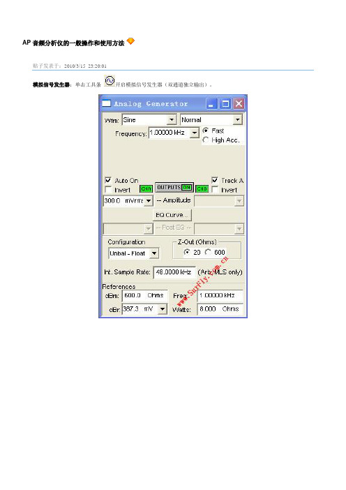
AP音频分析仪的一般操作和使用方法贴子发表于:2010/3/15 23:20:01模拟信号发生器:单击工具条开启模拟信号发生器(双通道独立输出)。
•Wfm: 选择产生信号波形。
一般测量使用Sine / Normal(典型正弦波波形),是由模拟部分硬件产生的低失真度的信号,20Hz –20KHz时失真度< 0.0001%。
•Frequency: 设定信号频率,Sine / Normal模式下可设定频率范围:10Hz –204KHz。
输入时可加单位“k(千)”。
•Fast / High Acc.: 选择快速(+/-0.5%)或高精度(+/-0.03%)模式。
快速模式适合于一般音频测试,建议在需高速自动测试中使用。
高精度模式产生精确的信号频率,但需150mS –750mS的设定反应时间,建议手动测试时选用此模式提高测量精度。
•Amplitude: 设定信号振幅。
平衡输出时可设定振幅:<10uV –13.33Vrms。
非平衡输出时可设定振幅:<10uV –26.66Vrms。
输入时可加单位“n(纳),u(微),m(毫)”。
注意因信号发生器的输出阻抗的差异,和DUT输入阻抗的差异,会导致DUT输入端的信号电压偏低于APWIN的设定电压。
•OUTPUT ON/OFF: 信号发生器输出开关。
按钮绿色是开启,灰色是关闭。
•Auto On: 如选中,在扫频开始时自动开启信号发生器,结束时自动关闭信号发生器。
•CHA On/Off: A通道输出开关。
按钮绿色是开启,灰色是关闭。
作用在信号发生器输出开关前。
•CHB On/Off: B通道输出开关。
按钮绿色是开启,灰色是关闭。
作用在信号发生器输出开关前。
•Invert: 信号相位180度反转。
可分别控制A / B通道。
通常反转B通道相位用于Dolby ProLogic测量。
•Track A: 如选中则同时设定A / B通道的振幅,反之分别设定。
•EQ Curve: 选用APWIN或自定的均衡器曲线。
Group550操作手册

接受许可协议
选择国家
输入站点名称(默认即可)
设置IP地址(手动输入)
删除管理员密码
取消邮件注册
修改IP地址后不需要重启
主屏幕界面
配置主屏幕图标
主屏幕图标是本地界面下面中间显示的图标,一次显示三个。默认情况下,用户在此位置中看到下表中所示的 图标。
操作要点与注意事项
给遥控器电池充电
谢 谢!
连接音频输入
RealPresence Group 300、500 和 550系统可支持以下任何设备: • 两个 RealPresence Group 麦克风ealPresence Group 700 系统可支持以下任何设备: • 三个 Polycom RealPresence Group 麦克风阵列或三个 Polycom HDX 麦克风阵列
三个polycomrealpresencegroup麦克风阵列或三个polycomhdx麦克风阵列音频输入配置遥控器操作配置遥控器通道id用手或其他物体挡住遥控器红外信号的发射方向并按住和持续23秒钟
Group550操作手册
目录
设备界面 系统初始化 操作要点与注意事项
终端背板界面
系统初始化
选择语言
连接摄像头(三) 双摄像头支持
连接摄像头(四)
配置视频输入设置 指定此输入用于图像还是内容。 在此版本的 RealPresence Group 550 中,您只能将输入 1 和输入 2 设置为图像,将输入 3 设置为内容。
配置摄像头预设
预设允许用户: • 使摄像头自动朝向房间内的预定义位置。 • 选择视频源。 如果摄像头支持摇摄、俯仰、变焦功能,且已设置为“图像”,则可以使用遥 控器、小键盘或 Polycom Touch Control 为其创建最多 10 个预设摄像头位置。 如果允许控制远端站点摄像头,则可以为远端站点摄像头创建 10 个预设。
apx500音频分析仪使用简易图解
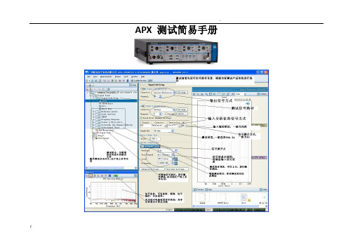
APX 测试简易手册c信号路径的设置蓝牙播放器测试1.在信号源路径中选择bluetooth.2.点击settings 进行配对连接。
3.选择A2DP Source HSP4.点击Scan for devices 搜索被测产品5.点击pair 进行配对6.连接A2DP 协议7.开始测试相关测试项目c蓝牙主机(Audio Gateway)的测试1.Input Configuraton 路径设置为bluetooth2.点击settings 进行配对连接。
3.选择A2DP link ( Hand-free 或者headset)4.点击Scan for devices 搜索被测产品5.点击pair 进行配对6.连接A2DP 协议7.开始测试相关测试项目c功放测试1.根据实际接线,设置信号源的输出信号方式2.根据实际接线,设置分析仪的输入信号方式cDVD、CD的测试1.信号源设为none2.分析仪接口设置与实际接线方式一致。
c选择测试项目根据测试需求增加项目cc电平测试1.设置信号源输出波形2.设置信号源大小3.设置信号源频率4.打开信号源开关5.读取测量值c失真测试1设置信号源输出波形,2设置信号源大小3设置信号源频率4打开信号源开关c5按需求设置滤波器6读取测量值信噪比测试1设置信号源输出波形2设置信号源大小3设置信号源频率4打开信号源开关c5按需求设置滤波器6读取测量值频率扫描测试1.设置信号源波形2.设置信号源大小3.设置信号源开始频率,结束频率,扫描点数4.设置滤波器c5.点击Start 开始测试。
总谐波失真加噪声频率扫描测试1设置信号源波形2设置信号源大小3设置信号源开始频率,结束频率,扫描点数c4设置滤波器5 点击Start 开始测试生成测试报告cc。
2015年P型音频分析仪数字多功能多元器测量仪数据手册说明书

The 2015-P Audio Analyzing Digital Multimeter and the 2015 Total Harmonic Distortion Multimeter combine audio band quality measurements and analysis with a full-function 6½-digit DMM. Test engineers can make a broad range of voltage, resistance, current, frequency, and distortion measurements, all with the samecompact, half-rack measurement instrument. The 2015-P offers additional processing capacity for frequency spectrum analysis.Key Features•THD, THD+Noise, and SINAD measurements •20 Hz–20 kHz sine wave generator •Fast frequency sweeps•2015-P identifies peak spectral components •Sine wave generator maximum amplitude: 4 Vrms single-ended or 8 Vrms differential output •Individual harmonic magnitude measurements • 5 standard audio shaping filters •13 DMM functions (6½ digits)•GPIB and RS-232 interfaces2015 6½-Digit THD Multimeter2015-P 6½-Digit Audio Analyzing MultimeterDatasheetFrequency Domain Distortion AnalysisFor applications such as assessing non-linear distortion in components, devices, and systems, DSP-based processing allows the 2015 and 2015-P to providefrequency domain analysis in conventional time domaininstrum ents. They can measure Total Harmonic Distortion (THD) over the complete 20 Hz to 20 kHz audio band. They also measure over a wide input range (up to750 Vrms) and have low residual distortion (–87 dB). The THD reading can be expressed either in decibels or as a percentage.In addition to THD, the 2015 and 2015-P can com p ute THD+Noise and Signal-to-Noise plus Distortion (SINAD). For analyses in which the individual harmonics are the criteria of greatest interest, the instruments can report any of the (up to 64) harmonic magnitudes that can be included in the distortion measurements. The user can program the actual number of harmonics to be included in a computation, so accuracy, speed, and complexity can be optimized for a specific application. (See Figure 1.)Optimized for Production TestingThe 2015 and 2015-P can perform fast frequency sweeps for characterizing audio-band circuitry in production test systems. For example, the instruments can execute a single sweep of 30 frequencies and transmit both rms voltage readings and THD readings to a computer in only 1.1 seconds. With that data, a complete frequency response analysis and a harmonic distortion vs. frequency analysis can be performed in a very short time. Thus high speed testing of the audio performance of a high volume device such as a cellular telephone can be performed without reducing the number of tests or reducing themeasurements in each test. With these instruments, which are optimized for production testing, test engineers can lower test times, in comparison to test speeds achievable with general purpose audio analyzers, without sacrificingproduction test quality.Datasheet2Figures 2, 3, and 4 demonstrate how the 2015 and 2015-P can provide both time domain and frequency domain measurements in a single test protocol. Figure 2 shows a s ample test system schematic with a telecommunication device in a loop back mode test. The Audio Analyzing DMM’s source provides a stimulusf requency sweep, and the Audio Analyzing DMM measures the response from the microphone circuit. Figure 3 shows the resulting frequency domain analysis of the THD and the first three harmonics as a function of frequency. Figure 4 shows the time domain analysis of micro p hone circuit output voltage as a function of frequency.Figure 2. Total Harmonic Distortion Analysis and Frequency Response of a Portable Wireless Telecommunication DeviceFigure 1. Frequency Spectrum of 1kHz Square Wave. Figure 1 shows a plot of a square wave’s harmonics (frequency components) computed and transmitted to a personal computer by the 2015. A square wave’s spectral content consists of only odd harmonics whose magnitudes are (1/harmonic number × the magni t ude of the fundamental). For example, the magnitude of the third harmonic is 1⁄3 the magnitude of the fundamental.Figure 3. THD and 2nd, 3rd, and 4th Harmonics as a Function of FrequencyFigure 4. Frequency Response 32015 6½-Digit THD Multimeter2015-P 6½-Digit Audio Analyzing MultimeterDual Output SourceThe 2015 and 2015-P include an internal audio band sine wave source for generating stimulus signals. A second output, the inverse of the first output, is also available, simplifying the testing of differential input circuits for common mode or noise cancellation performance. The 2015 and 2015-P have a 4 Vrms single-ended output and 8 Vrms differential source output.Wide Selection of Audio FiltersFive industry-standard bandpass filters are provided for shaping the input signal for audio and tele c om m u n ica t ion applications. Available filters include the CCITT weighting filter, CCIR filter, C-message filter, CCIR/ARM filter, and “A” weighting filter (see Figures 5a–5e ). The 2015 and 2015-P provide programmable, high cutoff (low pass) and low cutoff (high pass) filters. Furthermore, the two filters can be implemented together to form a bandpass filter. The programmable filters can be used to fi lter out noise generated by electromechanical machinery on the production floor or to simulate other types of system transmission charac t eristics.Figure 5a.Figure 5b.Figure 5c.Figure 5d.Figure 5e.Datasheet4Broad Measurement FlexibilityIn addition to their THD, THD+Noise, SINAD, and individual har m onic measure m ent capabilities, the instruments provide a compre h en-sive set of DMM functions, including DCV, ACV, DCI, ACI, 2WΩ, 4WΩ, temperature, frequency, period, dB, dBm, and continuity measure m ents, as well as diode testing. This multi-functional design minimizes added equipment costs when config u ring test setups.Wide Band or Narrow Band Noise MeasurementsThe 2015 and 2015-P are capable of measuring both wide band noise and narrow band noise. Alternatively, these instruments’ DSP (digitalsignal processing) capabilities allow users to make frequency domain measurements of RMS voltage noise over the 20 Hz–20 kHz frequency audio band or a narrow portion of the band. Furthermore, noisemeasurements can be extracted in the presence of a stimulus signal for fast signal-to-noise c omputations.Spectrum AnalysisThe 2015-P has internal computationalcapabilities that allow it to characterize an acquired signal spectrum. This instrument can identify and report the frequency and amplitude of the highest value in a complete spectrum or within a specified frequency band. It can also identify additional peaks in descending order of magnitude (see Figure 6). The 2015-P’s on-board capabilities make it simple to obtain a thorough analysis of a frequency spectrum more quickly and with little or no need for external analysis software.Figure 7. Rear panel of both modelsFigure 6. The 2015-P directly identifies peak values of the f requency spectrum.Typical Applications• Wireless communication device audio quality testing • Component linearity testing• Lighting and ballast THD limit conformance testing • Telephone and automotive speaker testing2015 6½-Digit THD Multimeter2015-P 6½-Digit Audio Analyzing Multimeter SpecificationsDistortion CharacteristicsVoltage Range 100 mV, 1 V, 10 V, 100 V, 750 V (user selectable).Input Impedance 1 MΩ paralleled by <100 pF.Display Range 0–100% or 0–100.00 dB.Resolution 0.0001% or 0.00001 dB.Fundamental Frequency Range 20 Hz–20 kHz.Harmonic Frequency Range 40 Hz–50 kHz.Frequency Resolution 0.008 Hz.Frequency Accuracy ±0.01% of reading.Frequency Temperature Coefficient≤100 ppm over operating temperature range.Distortion Measurement Audio FiltersNone C-MessageCCITT Weighting CCIR/ARMCCIR “A” WeightingNumber of Harmonics Included in THD Calculation2 to 64 (user selectable).HI and LO Cutoff Filters (bus settable)20 Hz–50 kHz. Can be combined to form brickwall bandpass filter.Distortion Measurement Reading Rate3Frequency Sweep Reading RateNotes1. Input signal at full scale.2. VIN ≥20% of range and harmonics > –65 dB.3. Speeds are for default operating conditions (*RST), and display off, auto range off, binary data transfer, trig delay = 0.4. Typical times: frequencies in 400–4 kHz range, binary data transfer, TRIG DELAY = 0, Display OFF, Auto Range OFF. Data returned is THD measurement plus AC voltage.5Datasheet6Generator CharacteristicsFrequency Range 10–20 kHz.Frequency Resolution 0.007 Hz.Frequency Accuracy±(0.015% of reading + 0.007 Hz) 1.Frequency Temperature Coefficient <100 ppm over operating temperature range.Source OutputWaveform Sinewave.Amplitude Range 2 V rms (50 Ω and 600 Ω) or 4 V rms (HI Z).Amplitude Resolution 0.5 mV rms (50 Ω and 600 Ω) or 1 mV rms (HI Z).Amplitude Accuracy±(0.3% of setting + 2.5 mV)1, 4.Amplitude Temperature Coefficient Typically 0.015%/°C.Amplitude Flatness ±0.1 dB 1, 4, 5.Output Impedance 50 Ω ± 1 Ω or 600 Ω ± 10 Ω, user selectable.THD –64 dB 6.Noise100 µV rms 2.DC Offset Voltage±2.5 mV 1.Inv/Pulse Output (Sinewave Mode)Frequency Same as source output.Amplitude Range 2 V rms (50 Ω and 600 Ω) or 4 V rms (HI Z).Amplitude Resolution 0.5 mV (50 Ω and 600 Ω) or 1 mV rms (HI Z).Amplitude Accuracy ±(2.0% of setting + 2.5 mV) 1, 4.Amplitude Flatness ±0.1 dB 1, 4, 5.Output Impedance Same as Source Output setting.THD –64 dB 6.Noise100 µV rms 2.DC Offset Voltage±1.1 mV typ., ±13 mV max.1Inv/Pulse Output (Pulse Mode)Frequency Same as source output.Duty Cycle 45% ±3%.Output Impedance Same output impedance as the source output.Amplitude 0.0 V ±0.07 V to 4.9 V ±0.12 V pulse open circuit 1, 3. 0.0 V ±0.05 V to 3.3 V ±0.11 V pulse open circuit 1, 3.Overshoot 1.0 V maximum pulse open circuit 3.0.2 V maximum with 100 Ω load pulse open circuit 3.Undershoot 1.1 V maximum pulse open circuit 3.0.45 V maximum with 100 Ω load pulse open circuit 3.Notes1. 1 year, 23°C ±5°C.2. Measured at V OUT = 0 V with gain 100 amplifier and 2-pole 50 kHz low pass filter, Inv/Pulse in sinewave mode, HI Z output impedance, and no load.3. With HI Z output impedance and 1m 50Ω coaxial cable.4. HI Z output impedance, no load.5. 4 V output.6.THD measurement includes harmonics 2 through 5, 1 V rms output, HI Z, no load.2015 6½-Digit THD Multimeter2015-P 6½-Digit Audio Analyzing MultimeterDC Characteristicsor SLOW (10 PLC) or MED (1 PLC) with filter of 10.Conditions MED (1 PLC) 12Range Change 3 50/s.Function Change 345/s.Autorange Time 3, 10<30 ms.ASCII readings to RS-232 (19.2k baud)55/s.Max. Internal Trigger Rate 2000/s.Max. External Trigger Rate 400/s.7Datasheet8DC GeneralLinearity of 10 VDC Range±(1 ppm of reading + 2 ppm of range).DCV, Ω, Temperature, Continuity, Diode Test Input Protection1000 V, all ranges.Maximum 4W Ω Lead Resistance 10% of range per lead for 100 Ω and 1 kΩ ranges; 1 kΩ per lead for all other ranges.DC Current Input Protection 3 A, 250 V fuse.Shunt Resistor 0.1 Ω for 3 A, 1 A, and 100 mA ranges. 10 Ω for 10 mA range.Continuity Threshold Adjustable 1 Ω to 1000 Ω.Autozero Off Error Add ±(2 ppm of range error + 5 µV) for <10 minutes and ±1°C change.Overrange120% of range except on 1000 V, 3 A, and Diode.Speed and Noise RejectionDC Notes1. Add the following to ppm of range accuracy specification based on range: 1 V and 100 V, 2 ppm; 100 mV, 15 ppm; 100 Ω, 15 ppm; 1 kΩ–1 MΩ, 2 ppm; 10 mA and 1 A, 10 ppm; 100 mA, 40 ppm.2. Speeds are for 60 Hz operation using factory default operating conditions (*RST). Autorange off, Display off, Trigger delay = 0.3. Speeds include measurement and binary data transfer out the GPIB.4. Auto zero off.5. Sample count = 1024, auto zero off.6. Auto zero off, NPLC = 0.01.7. Ohms = 24 readings/second.8. 1 PLC = 16.67 ms @ 60 Hz, 20 ms @ 50 Hz/400 Hz. The frequency is automatically determined at power up.9. For signal levels >500 V, add 0.02 ppm/V uncertainty for the portion exceeding 500 V.10. Add 120 ms for ohms.11. Must have 10% matching of lead resistance in Input HI and LO.12. For line frequency ±0.1%.13. For 1 kΩ unbalance in LO lead.14. Relative to calibration accuracy.15. Specifications are for 4-wire ohms. For 2-wire ohms, add 1 Ω additional uncertainty.16. For rear inputs. Add the following to Temperature Coefficient “ppm of reading” uncertainty: 10 MΩ 70 ppm, 100 MΩ 385 ppm. Operating environment specified for 0° to 50°C, 50% RH at 35°C.17. When properly zeroed.True RMS AC Voltage and Current Characteristics2015 6½-Digit THD Multimeter2015-P 6½-Digit Audio Analyzing MultimeterHigh Crest Factor Additional Error ±(% of reading) 7Crest Factor 1–2 2–3 3–4 4–5Additional Error 0.05 0.15 0.30 0.40AC Operating Characteristics2Additional Low Frequency Errors ±(% of reading)AC System Speeds 2, 5Function/Range Change 64/s.Autorange Time <3 s.ASCII Readings to RS-232 (19.2k baud) 450/s.Max. Internal Trigger Rate 4300/s.Max. External Trigger Rate 4260/s.AC GeneralInput Impedance 1 MΩ ±2% paralleled by <100 pF.ACV Input Protection 1000 Vp.Maximum DCV 400 V on any ACV range.ACI Input Protection 3 A, 250 V fuse.Burden Voltage 1 A Range: <0.3 V rms. 3 A Range: <1 V rms.Shunt Resistor 0.1 Ω on all ACI ranges.AC CMRR >70 dB with 1 kΩ in LO lead.Maximum Crest Factor 5 at full scale.Volt Hertz Product ≤8 × 10⁷ V·Hz.Overrange 120% of range except on 750 V and 3 A ranges.AC Notes1. Specifications are for SLOW rate and sinewave inputs >5% of range.2. Speeds are for 60 Hz operation using factory default operating conditions (*RST). Auto zero off, Auto range off, Display off, includes measurement and binary data transfer out the GPIB.3. 0.01% of step settling error. Trigger delay = 400 ms.4. Trigger delay = 0.5. DETector:BANDwidth 300, NPLC = 0.01.6. Maximum useful limit with trigger delay = 175 ms.7. Applies to non-sinewaves >5 Hz and <500 Hz. (Guaranteed by design for crest factors >4.3.)8. Applies to 0°–18°C and 28°–50°C.9. For signal levels >2.2 A, add additional 0.4% to “of reading” uncertainty.10. Typical uncertainties. Typical is defined as follows: Two sigma, 95% of all instruments are expected to measure <0.35% of reading; three sigma, 99.7% of all instruments are expected tomeasure <1.06% of reading.9Datasheet10Triggering and MemoryReading Hold Sensitivity 0.01%, 0.1%, 1%, or 10% of reading.Trigger Delay0 to 99 hours (1 ms step size).External Trigger Latency 200 µs + <300 µs jitter with autozero off, trigger delay = 0.Memory1024 readings.Math FunctionsMath FunctionsRel, Min/Max/Average/StdDev (of stored reading), dB, dBm, Limit Test, %, and mX+b with user defined units displayed.dBm Reference Resistances1 to 9999 Ω in 1 Ω increments.Standard Programming LanguagesSCPI (Standard Commands for Programmable Instruments).Remote InterfaceRemote InterfaceGPIB (IEEE-488.1, IEEE-488.2) and RS-232C.Frequency and Period Characteristics1, 2Frequency Notes1. Specifications are for square wave inputs only. Input signal must be >10% of ACV range. If input is <20 mV on the 100 mV range, then the frequency must be >10 Hz.2. 20% overrange on all ranges except 750V range.Temperature CharacteristicsTemperature Notes1. For temperatures <–100°C add ±0.1°C and >900°C add ±0.3°C.2. Temperature can be displayed in °C, K, or °F.3. Accuracy based on ITS-90.4.Exclusive of thermocouple error.2015 6½-Digit THD Multimeter2015-P 6½-Digit Audio Analyzing Multimeter GeneralPower Supply 100 V / 120 V / 220 V / 240 V.Line Frequency 50 Hz to 60 Hz and 400 Hz, automatically sensed at power-up.Power Consumption 40 VA.Volt Hertz Product ≤8 × 10⁷ V·Hz.Safety Conforms to European Union Low Voltage Directive.EMC Conforms to European Union EMC Directive.Vibration MIL-PRF-28800F Class 3 Random.Warmup 1 hour to rated accuracy.Operating Environment Specified for 0°C to 50°C. Specified to 80% R.H. at 35°C and at an altitude of up to 2,000 meters. Storage Environment –40°C to 70°C.Dimensions:Rack Mounting 89 mm high × 213 mm wide × 370 mm deep (3.5 in × 8.38 in × 14.56 in).Bench Configuration (with handle and feet)104 mm high × 238 mm wide × 370 mm deep (4.13 in × 9.38 in × 14.56 in).Net Weight 4.2 kg (8.8 lbs).Shipping Weight 5 kg (11 lbs).Warranty 1 year.Ordering Information2015 Total Harmonic Distortion 6½-Digit Multimeter2015-P Audio Analyzing DMMSupplied Accessories1751 Safety Test LeadsQuick Start GuideCertificate of CalibrationAvailable AccessoriesCables/Adapters7007-1 Shielded IEEE-488 Cable, 1 m (3.3 ft)7007-2 Shielded IEEE-488 Cable, 2 m (6.6 ft)8501-1, 8501-2 Trigger-Link Cables, 1 m (3.3 ft), 2 m (6.6 ft)8502 Trigger Link Adapter Box8503 Trigger Link Cable to 2 male BNCs, 1 m (3.3 ft)7009-5 RS-232 CableRack Mount Kits4288-1 Single Fixed Rack Mount Kit4288-2 Dual Fixed Rack Mount Kit11Datasheet12GPIB InterfacesKPCI-488LPA IEEE-488 Interface/Controller for the PCI Bus KUSB-488BIEEE-488 USB-to-GPIB Interface AdapterPower Cord OptionsAO North America Power Plug (120 V, 60 Hz)A1 Universal Euro Power Plug (220 V, 50 Hz)A2 United Kingdom Power Plug {240 V, 50 Hz)A3 Australia Power Plug (240 V, 50 Hz)A4 Chile, Italy (220 V, 50 Hz)A5 Switzerland Power Plug (220 V, 50 Hz)A6 Japan Power Plug (100 V, 50/60 Hz)A7 Denmark Power Plug A8 Israel Power Plug A9 Argentina Power Plug A10 China Power Plug (50 Hz)A11 India Power Plug (50 Hz)A12 Brazil Power Plug (60 Hz)A99No power cordDocumentationInstruction Manuals (available at /tektronix-and-keithley-digital-multimeter/keithley-2015-series-thd-and-audio-analysis-multimeter ) 2015/2015-P THD Multimeter User’s Manual2015, 2015-P THD Multimeters Quick Reference Guide2015 6½-Digit THD Multimeter2015-P 6½-Digit Audio Analyzing MultimeterAvailable ServicesExtended Warranties2015-EW 1-Year KEITHLEYCARE Extended Warranty2015-3Y-EW 3-Year KEITHLEYCARE Extended Warranty2015-5YR-EW 5-Year KEITHLEYCARE Extended Warranty2015-P-EW 1-Year KEITHLEYCARE Extended Warranty2015-P-3Y-EW 3-Year KEITHLEYCARE Extended Warranty2015-P-5YR-EW 5-Year KEITHLEYCARE Extended WarrantyCalibration ContractsC/2015-3Y-STD KEITHLEYCARE 3-Year Standard Calibration PlanC/2015-3Y-DATA KEITHLEYCARE 3-Year Calibration with Data PlanC/2015-3Y-17025 KEITHLEYCARE 3-Year ISO 17025 Calibration PlanC/2015-5Y-STD KEITHLEYCARE 5-Year Standard Calibration PlanC/2015-5Y-DATA KEITHLEYCARE 5-Year Calibration with Data PlanC/2015-5Y-17025 KEITHLEYCARE 5-Year ISO 17025 Calibration PlanCalibration DataC/NEW DATA Calibration Data for New 2015 or 2015-PC/NEW DATA ISO ISO-17025 Calibration Data for New 2015 or 2015-PC/TRACE CHART Calibration Traceability Chart13Contact Information:Australia* 1 800 709 465Austria 00800 2255 4835Balkans, Israel, South Africa and other ISE Countries +41 52 675 3777Belgium* 00800 2255 4835Brazil +55 (11) 3759 7627Canada 180****9200Central East Europe / Baltics +41 52 675 3777Central Europe / Greece +41 52 675 3777Denmark +45 80 88 1401Finland +41 52 675 3777France* 00800 2255 4835Germany* 00800 2255 4835Hong Kong 400 820 5835India 000 800 650 1835Indonesia 007 803 601 5249Italy 00800 2255 4835Japan 81 (3) 6714 3010Luxembourg +41 52 675 3777Malaysia 180****5835Mexico, Central/South America and Caribbean 52 (55) 56 04 50 90Middle East, Asia, and North Africa +41 52 675 3777The Netherlands* 00800 2255 4835New Zealand 0800 800 238Norway 800 16098People’s Republic of China 400 820 5835Philippines 1 800 1601 0077Poland +41 52 675 3777Portugal 80 08 12370Republic of Korea +82 2 565 1455Russia / CIS +7 (495) 6647564Singapore 800 6011 473South Africa +41 52 675 3777Spain* 00800 2255 4835Sweden* 00800 2255 4835Switzerland* 00800 2255 4835Taiwan 886 (2) 2656 6688Thailand 1 800 011 931United Kingdom / Ireland* 00800 2255 4835USA 180****9200Vietnam 12060128* European toll-free number. If notaccessible, call: +41 52 675 3777Find more valuable resources at Copyright © Tektronix. All rights reserved. Tektronix products are covered by U.S. and foreign patents, issued and pending. Information in this publication supersedes thatin all previously published material. Specification and price change privileges reserved. TEKTRONIX and TEK are registered trademarks of Tektronix, Inc. All other trade namesreferenced are the service marks, trademarks or registered trademarks of their respective companies.071019.SBG 1KW-61135-1。
APX 500 音频分析仪 使用简易图解
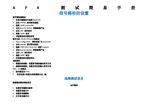
A P X测试简易手册信号路径的设置蓝牙播放器测试1.在信号源路径中选择bluetooth.2.点击settings 进行配对连接。
3.选择A2DP Source HSP4.点击Scan for devices 搜索被测产品5.点击pair 进行配对6.连接A2DP 协议7.开始测试相关测试项目蓝牙主机(Audio Gateway)的测试1.Input Configuraton 路径设置为bluetooth2.点击settings 进行配对连接。
3.选择A2DP link ( Hand-free 或者headset)4.点击Scan for devices 搜索被测产品5.点击pair 进行配对6.连接A2DP 协议7.开始测试相关测试项目功放测试1.根据实际接线,设置信号源的输出信号方式2.根据实际接线,设置分析仪的输入信号方式DVD、CD的测试1.信号源设为none2.分析仪接口设置与实际接线方式一致。
选择测试项目根据测试需求增加项目电平测试1.设置信号源输出波形2.设置信号源大小3.设置信号源频率4.打开信号源开关5.读取测量值失真测试1设置信号源输出波形,2设置信号源大小3设置信号源频率4打开信号源开关5按需求设置滤波器6读取测量值信噪比测试1设置信号源输出波形2设置信号源大小3设置信号源频率4打开信号源开关5按需求设置滤波器6读取测量值频率扫描测试1.设置信号源波形2.设置信号源大小3.设置信号源开始频率,结束频率,扫描点数4.设置滤波器5.点击Start 开始测试。
总谐波失真加噪声频率扫描测试1设置信号源波形2设置信号源大小3设置信号源开始频率,结束频率,扫描点数4设置滤波器5 点击Start 开始测试生成测试报告。
APx555音频分析仪音频测试仪操作说明书
• 步径扫频需要在Add mearsurement 里面添加 Stepped Frequency Sweep
APx Training 深圳市愛普泰科電子有限公司
Slide 18
• 起始電壓 • 結束電壓
• 掃描點數 • 掃描信號頻率
•资料仅供参考
測試步驟二之幅度掃描參數設置
• 低通,高通, 加權濾波器
o 1K to 1M o 平均处理 o 窗函数 o AC/DC 耦合
• 信号电压表
o 电平 o 总谐波失真加噪声 THD+N o 频率
• Status Bit信息
數字信號元數據的狀態位
• Aux控制口 • 特点:
o 独立地实时显示 o 可变尺寸
APx Training 深圳市愛普泰科電子有限公司
信號監視
注意: 對於所選擇的每個音頻測試參數, 都
需要對其進行對應的測試參數設置, 即每個測 試參數都有獨立的參數設置
APx Training 深圳市愛普泰科電子有限公司
Slide 17
• 起始頻率 • 結束頻率
•资料仅供参考
測試步驟二之頻率掃描參數設置
• 掃描點數 • 掃描電壓 • 低通, 高通, 加權濾波器
• 2通道或8通道輸出
• 平衡,非平衡輸入/輸出接口
• 正弦波信号 0.001Hz 到 80.1 kHz,Apx555可达 到204kHz, 频率精准度 3 ppm
• 正弦波输出电压 :1.0 uV to 26.66 V (平衡) 或 者 :1.0 uV to 13.33 V (非平衡). 精度约为 0.05 dB(不同型號儀器輸出能力有區別)
APx Training 深圳市愛普泰科電子有限公司
Slide 16
【音频分析仪】音频分析仪使用教程
【音频分析仪】音频分析仪使用教程AbstractThe system based on microprocessor uses FPGA to carry out FFT algorithm in order to analyse the audio signal. It contains a signal conditioning module, AD637 detector module, A / D sampling module and the FFT algorithm processing module. The signal conditioning consists of program-controlled amplifier and low-pass filter to achieve signal preprocessing. The system uses 20-bit fixed-point 4096-point FFT calculation, to the accurate measurement of the frequency range 10-10kHz, the amplitude range of 100mVpp ~ 10Vpp the input signal power and total power, frequency resolution up to 10Hz, and analysis of signal distortion degrees, to determine the periodic signal, and measure its cycle. In addition, the system also hasa storage playback and display features such as measurement results.一、系统方案论证与比较1.方案比较与选择(1)总体方案比较与选择系统核心在于对信号进行频谱分析,从而实现功率谱、失真度等参数测量。
APX500音频分析仪使用简易图解
Leva TTO+S f Bi ts 289.2 uiVnus 290. 7 L /121S 回HiTf( 痢斗Qject ” AP K SDO ¥2.9 Filt Vis# 宦匕匕勺卫 aniEiitb Ti uj e21 T OQI I S 世Htlp W S 国皿IS 面匝匝IB 信号路径设置 ■j" ”圍住frpj ?et :| ■/归鹉事al 曲till D u.'Lp a.t £ OXldEl. gJLT ■&!. JL Conr s act&r ; .信号源接口设置,CD 类设为畑氏 蛊郵輻嶠实际接线q CGM.ector : Cbarjiels B^zidwidt A : BH I 廿口田 ■i - :Add …窃Ad&珀环 「画鞠坯*rt 3f Dat^. CutpuL V UIUL tor 1 '<■■■□? Si? 7KI-+H Irequenzy Respo: £i to Hoi£? Crcsslalk, One Q L ^CI T L -1 Uiidi^i v 2ntercharo.el thase Maasurement... Confirms at i?i An al o g I'nlialaiiEe T | : E Ik, JF_ 9D kMi D eviqe Usidea- T est. S e t i i F-gs Dd?y : O-dlO s Vfiri fy E i OTI 吕 Set tilths -. L&t eli.」 3wi. Se.1 .. FFT Spcctrwi H QU t?r Refer to the Melp fils infcrrnat.on al>uu.l curnpu.libit : 孕辺 ■dun -亡也二. for 测试前须先根据黨际 情况设置测试路径参 数 Output ; 选择测试项目 根据测试需求增加项目 i *19 :Z
550 使用手册(中文版)
微调(Clarifier)
仅接收:+ / – 50 Hz、+ / – 150 Hz、+ / – 1K Hz
射频输出功率
125W 语音 / 100W ± 1 dB 双音调 / 10W PEP(可调)
发
负载率
配散热风扇可达 100%
射
无用边带抑制
优于-50dB
技
术
谐波抑制
优于-40dB
指
载波抑制
优于-50dB
GPS 系统
NMEA 0183 Ver2.0 信令格式
本机静重
3.6 公斤
体积
250 ㎜×75 ㎜×300 ㎜(宽×高×深)
扫描类型
选呼、自动增益控制、语音(一般模式)
扫描信道
500 个可编程信道
扫描速度
选呼扫描:500 毫秒 非选呼扫描:100 毫秒~99 秒可调
灵敏度
0.35µV/10 dB
选择性
2.3 KHz/-6 dB
4.2 KHz/-60 dB
接
杂波抑制
优于-60dB
收
技
抗阻塞
优于 70dB(20 KHz)
术
互调抑制
优于 70dB(30 KHz/60 KHz)
指 自动增益控制(AGC)特性 输入 3µV~3V 输出变化小于 1dB
标
音频失真度
小于 5%
音频输出
2W/8Ω
通带滤波器
± 3 KHz
宝丽 550 单边带短波电台
使用手册 (中文版)
BH7KEM 编辑录入
1
目录
1.0 技术指标...................................................................................4 1.1 概述..........................................................................................5 2.0 安装..........................................................................................5 3.0 操作..........................................................................................6 3.1 前面板说明................................................................................6 3.2 编程...........................................................................................7 3.3 信道转换....................................................................................9 3.4 微调...........................................................................................9 3.5 发射频率监视...........................................................................10 3.6 静噪..........................................................................................10 3.7 报警..........................................................................................10 3.8 2182 海难警报..........................................................................11 3.9 天线调谐...................................................................................11 3.10 工作模式...................................................................................11 3.11 扫描...........................................................................................12 3.12 选呼...........................................................................................12 3.13 电话拨号....................................................................................13 3.14 GPS 信息传送............................................................................16 3.15 寻呼............................................................................................18 3.16 状态信息接收..............................................................................18 3.17 信息记录.....................................................................................20 3.18 功能菜单.....................................................................................21 3.19 调谐接收.....................................................................................23 3.20 扫描接收.....................................................................................24 3.21 背面板端口.................................................................................24 4.0 主机及选配件..............................................................................26 5.0 外部设备.....................................................................................26 6.0 重要提示.....................................................................................27
APX500操作指导

Verify Connection
30
▪ 通过下方的选择器选择要显示的结
果类型
➢ 设定单位
▪ 通过Add添加可以显示的结果类型
➢ Primary Result – 原始结果 ➢ New Result ➢ Derived Result-衍生结果
3
模拟输入输出出接口
4
数字接口(DIO)/增强型数字接口(ADIO)
▪ 数字接口和增强型数字接口外观相同
➢ 平衡接口
• 支持AES3,EBU-3250,IEC60958-4
➢ 非平衡接口
• 支持AES3-id,SPDIF,IEC60958-3
➢ 光纤接口
• Toslink
▪ 增强型数字接口
➢ APx555 标准接口, APx52x/58x可选配件 ➢ Jitter功能
▪ 输入
➢ 可以设定两组相对输入幅度
• dBrA,dBrB
➢ 可以设定声压级幅度
• dBSPL
➢ dBm: dBm的参考负载 ➢ Watts: 功率的参考负载
29
Reference界面
▪ 在搭建环境时,快速验证连接有效性 ▪ 打开Generator, 设定信号参数
➢ 在右侧的”结果显示”显示窗口检查信号
▪ Jitter
➢ 和Advanced Master Clock(AMC) 一起可以测量 和产生Jitter
6
▪ 可选配件
➢ 除APx515外的APx仪器
▪ 全兼容HDMI1.3a ▪ 兼容HDMI1.4a ARC(Audio Return Channel) ▪ Source 和 Sink 支持 CEC
APX500音频分析仪使用简易图解
APX测试简易手册蓝牙播放器测试1. 在信号源路径中选择 bluetooth.2. 点击settings 进行配对连接。
3. 选择 A2DP Source HSP4. 点击Scan for devices 搜索被测产品5. 点击pair 进行配对6. 连接A2DP 协议7. 开始测试相关测试项目蓝牙主机 (Audio Gateway)的测试ml •嚼i*F w 口**™.“ Ij lhradn<^.lL r«i irrwT«r™iriUi>L4 血 & JC C DC kv«JE UtzSw 1-iitM-V Q DdQ ■V<rj| jp- 'lit 4*1mi"f二“_仃Tail Chicd Kll r^aravJ a VL*ar*L-R BE j»r 1__F^O-flrHia J-: 1HU*8C111h2 1-雌才播於器匕选择MSP largeL生扫描被测产品,lOOu3.配对也协议1()1005.F 1 TUrl E MXJ a❹ I LIAA 針T” E M 'EA+. □」IHweiiW L™isII |~~],_i l^val ^gfnx. □」TIM• Fr*f*w«fTT r~L 」W LP J t# Ax-34 fcvtne * L ,^J <illh,. CRmUril, I* T . _( In* vr-rlirjal fliiMbsH Fh EjL'lrwshl连接协议]片* 2fcj*:pj*. ' "“E L 「W■■Lu nln£<•:■*■_ | 5" i'Sa* njaz •.単 i© ,■ a2. 点击settings 进行配对连接。
3. 选择 A2DP link ( Hand-free 或者 headset)4. 点击Scan for devices 搜索被测产品5. 点击pair 进行配对6. 连接A2DP 协议7. 开始测试相关测试项目功放测试1. 根据实际接线,设置信号源的输出信号方式1蓝才输入测试/殛 <4閔・出rtHh P QSK I哲"出d 2T1讨2 1上i 妲曲■ *叶■ £} 电讣■!比电■卑"曲 liLF 1Li"丄/jT歼也卜_ L 丄Jf -同二I ■和三匸匹"S LK ^I L J V QJL Tmja I V I LE &Dlt| 0 ETror lai t• It hi mH Lmls • 口7 It Ou TrtlU* LJ ・J h ■电ii ・B 十二 j Sin-Jil t«[_]& gMttlJrr S rrik*i rh«r ・l Fl«4feAdj lifl H.TU MH1A*1 1上4・> ti/Lhr 4 nTf M . “li□ LoiiFh udi Tlw*.wtEIlj| 口 l|.:nnir.li|i i;® nrwchwri.J44VEDD B rJVnr< uQST F -I ^SOFT E hfi Idr-aChi选择协议-20krill p lEUsr*!、口4"財讪吓厂'-vrii rl-arZ XIBU I E打描产品hr-doL^lai rm Rf-'HraMiE M ISKI liliiii L —rl-才口打[=I J祝对AA 亍占■ hUti.JL ”. | | ■承!■'.-LlX…Filr 爭亡円岂已asuiewKn"± Preset Jpuls VflndoM Ne^>萨1 ■匕U 囹十剤J U |口I™? | 4;^Jdtls klqiln [j^a右li. _ 仙fZ P*lh "hjp::SJ :21 」-叵一g口-叵"詡壮Fxtklh叵一乳却心Fi」h他-总L.poj.Andie P-'Rci-;匚a APxB口亡£> nH T(Lat 3 D& Huth ©E TTOF□i__LU □L J—_ [TL J 匚—ELrF>T±TlCTLc^tl an 5 IH:*MFt艸4沁片久山a uCf . E£«ilJC1 *r*l 各I M Eft l4li t□CM C师二al IlwljLVsRii .* sre tiKroiBl tJ-i^i-B_j J i »j«p*4 F F■从弋用ti可□尸□咼L!(r □常□常nr □L□兰口皆□r LI ITLm4G BTBF;tl舐W E LtTel CJ. OOCOi klkDmUi^n g TOO 总-2C OK: k*k.) riiwc.4n»+K m吠轉TJBtlf .tvttl1JA Uni L ri>TO l>*fLD L at-t iu* F L I J H* ? ail ? t?F]DL'ffKitrtL™ Ptr'-dnwt Lrme-1. 理) mun Mi M«uv«Hbl .$8 63 Zh# ' Ji j *■ •Sf5+1. D|DVD、CD的测试1. 信号源设为none2. 分析仪接口设置与实际接线方式一致。
APx555音频分析仪音频测试仪操作说明书

測試步驟一之信號路徑設置
• 任何測試開始前
• Signal path setup 信號路 徑設置
①輸入/輸出(平衡、非平衡) ②通道數 2通道 ③測試帶寬設置
• 檢驗各項設置
• 提供檢驗設置是否正確的 方法
• 打開Generator開關 • 檢查輸出是否正確,如果
• 适用音頻分析儀
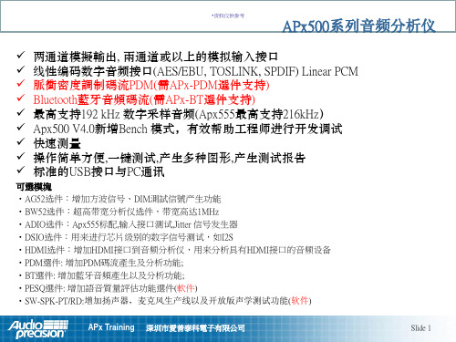
APx515 APx520, APx521 APx525 APx526 APx585 APx586 APx555
測量功能
• 輸出電壓 LEVEL • 總諧波失真 THD+N • 頻率響應 FREQUENCY RESPONSE • 分離度 CROSSTALK • 信噪比 SNR • 相位 PHASE • 互調失真 DIM,DFD,MOD,
BW52选件:超高带宽分析仪选件,带宽高达1MHz ADIO选件:Apx555标配,输入接口测试,Jitter 信号发生器 DSIO选件:用来进行芯片级别的数字信号测试,如I2S HDMI选件:增加HDMI接口到音频分析仪,用来分析具有HDMI接口的音频设备 PDM選件: 增加PDM碼流產生及分析功能; BT選件: 增加藍牙音頻產生以及分析功能; PESQ選件: 增加語音質量評估功能選件(軟件) SW-SPK-PT/RD:增加扬声器,麦克风生产线以及开放版声学测试功能(软件)
非平衡输入,主要用于消费类音頻
平衡输入,主要用于专业音响、广播领域 兩通道/四通道系列硬件
八通道系列硬件
數字輸入/輸出模塊
• 數字接口類型
Balance: AES3,EBU-3250,IEC60958-4
Unbalance: AES3-id,SPDIF, IEC60958-3
• 數字音頻格式
Apx525使用说明+功能
Apx525使用说明目录1、APx525简介 (1)1.1 APx525简介 (1)1.2 APx525功能 (2)1.3 APx525优点 (2)2、APx525说明 (4)2.1 菜单栏 (5)2.2 工具栏 (7)2.3 测试向导 (8)2.4 监视器 (10)2.5 状态栏 (11)2.6 测量参数设置面板 (12)2.7 条形图面板 (16)2.8结果设置栏 (17)2.9 选择器 (18)1、APx525简介1.1 APx525简介APx525是2通道实时输入,输出快速音频分析仪,操作非常方便,简单。
不需要掌握很多的音频测量和编程经验,就能进行测试和编程操作。
大量测试项目模板已固化在电脑上,只需要选择你所需要的测试项目和要求,就可以产生自动化测试程序,自动产生各种格式的综合报告,包括图形,数字,也可以添加产品标记和公司名称。
APx是高速、高性能和友善用户而设计的。
创新发明包括“一按”测试,自动检测执行器,连续扫频技术等等,令测试17项数据只需约7秒。
APx525带2个平衡和2个不平衡输入和输出,在加上192K采样数字接口,有AES/EBU,TOSLINK光纤和SPDIF格式。
APx提供快,一按测试,结果可一页显示,数据,图形都带上下限自动检查。
通过智能对话选择,可非常快速和简单地选择滤波器和高级设定。
对于重复测试不同的输入和输出途径,可完全自动化执行,也可实时监查电平,波形和FFT频谱分析。
其他特别波形,例如方波和粉红噪声等等,可通过Apx的外置源模式播波,以测试CD、DVD和MP3播放机。
在大功率功放测试时,自动测量连续最大输出和峰值,可检视功率图谱和调控扫频,和其他符合CEA-2006和CEA-490A国际标准的测试。
APx突破性地产生信号低至0.1Hz,最大输入电压至300Vrms有效值(160V不平衡输入)和典型失真THD+N<-108(在1KHz,2.5V),没有其他同档次的产品有此高表现。
APX500音频分析仪使用简易图解

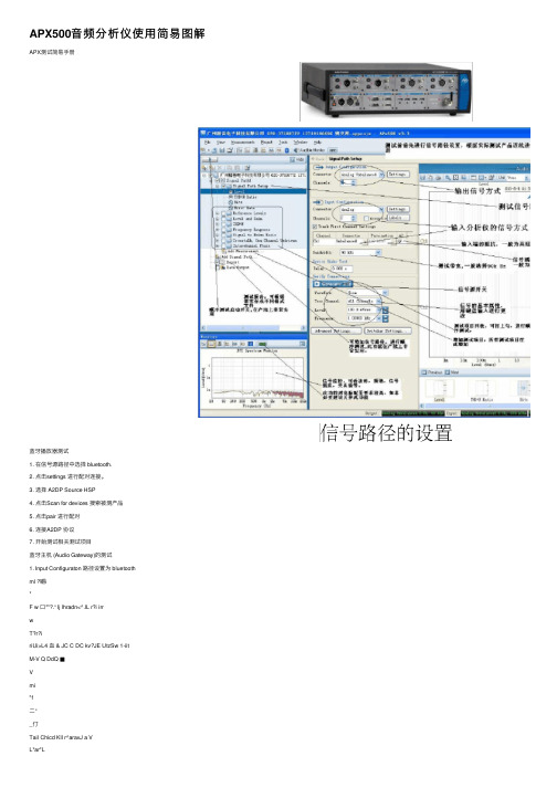
APX测试简易手册蓝牙播放器测试1. 在信号源路径中选择 bluetooth.2. 点击settings 进行配对连接。
3. 选择 A2DP Source HSP4. 点击Scan for devices 搜索被测产品5. 点击pair 进行配对6. 连接A2DP 协议7. 开始测试相关测试项目蓝牙主机 (Audio Gateway)的测试ml •嚼i*F w 口**™.“ Ij lhradn<^.lL r«i irrwT«r™iriUi>L4 血 & JC C DC kv«JE UtzSw 1-iitM-V Q DdQ ■V<rj| jp- 'lit 4*1mi"f二“_仃Tail Chicd Kll r^aravJ a VL*ar*L-R BE j»r 1__F^O-flrHia J-: 1HU*8C111h2 1-雌才播於器匕选择MSP largeL生扫描被测产品,lOOu3.配对也协议1()1005.F 1 TUrl E MXJ a❹ I LIAA 針T” E M 'EA+. □」IHweiiW L™isII |~~],_i l^val ^gfnx. □」TIM• Fr*f*w«fTT r~L 」W LP J t# Ax-34 fcvtne * L ,^J <illh,. CRmUril, I* T . _( In* vr-rlirjal fliiMbsH Fh EjL'lrwshl连接协议]片* 2fcj*:pj*. ' "“E L 「W■■Lu nln£<•:■*■_ | 5" i'Sa* njaz •.単 i© ,■ a2. 点击settings 进行配对连接。
3. 选择 A2DP link ( Hand-free 或者 headset)4. 点击Scan for devices 搜索被测产品5. 点击pair 进行配对6. 连接A2DP 协议7. 开始测试相关测试项目功放测试1. 根据实际接线,设置信号源的输出信号方式1蓝才输入测试/殛 <4閔・出rtHh P QSK I哲"出d 2T1讨2 1上i 妲曲■ *叶■ £} 电讣■!比电■卑"曲 liLF 1Li"丄/jT歼也卜_ L 丄Jf -同二I ■和三匸匹"S LK ^I L J V QJL Tmja I V I LE &Dlt| 0 ETror lai t• It hi mH Lmls • 口7 It Ou TrtlU* LJ ・J h ■电ii ・B 十二 j Sin-Jil t«[_]& gMttlJrr S rrik*i rh«r ・l Fl«4feAdj lifl H.TU MH1A*1 1上4・> ti/Lhr 4 nTf M . “li□ LoiiFh udi Tlw*.wtEIlj| 口 l|.:nnir.li|i i;® nrwchwri.J44VEDD B rJVnr< uQST F -I ^SOFT E hfi Idr-aChi选择协议-20krill p lEUsr*!、口4"財讪吓厂'-vrii rl-arZ XIBU I E打描产品hr-doL^lai rm Rf-'HraMiE M ISKI liliiii L —rl-才口打[=I J祝对AA 亍占■ hUti.JL ”. | | ■承!■'.-LlX…Filr 爭亡円岂已asuiewKn"± Preset Jpuls VflndoM Ne^>萨1 ■匕U 囹十剤J U |口I™? | 4;^Jdtls klqiln [j^a右li. _ 仙fZ P*lh "hjp::SJ :21 」-叵一g口-叵"詡壮Fxtklh叵一乳却心Fi」h他-总L.poj.Andie P-'Rci-;匚a APxB口亡£> nH T(Lat 3 D& Huth ©E TTOF□i__LU □L J—_ [TL J 匚—ELrF>T±TlCTLc^tl an 5 IH:*MFt艸4沁片久山a uCf . E£«ilJC1 *r*l 各I M Eft l4li t□CM C师二al IlwljLVsRii .* sre tiKroiBl tJ-i^i-B_j J i »j«p*4 F F■从弋用ti可□尸□咼L!(r □常□常nr □L□兰口皆□r LI ITLm4G BTBF;tl舐W E LtTel CJ. OOCOi klkDmUi^n g TOO 总-2C OK: k*k.) riiwc.4n»+K m吠轉TJBtlf .tvttl1JA Uni L ri>TO l>*fLD L at-t iu* F L I J H* ? ail ? t?F]DL'ffKitrtL™ Ptr'-dnwt Lrme-1. 理) mun Mi M«uv«Hbl .$8 63 Zh# ' Ji j *■ •Sf5+1. D|DVD、CD的测试1. 信号源设为none2. 分析仪接口设置与实际接线方式一致。
如何使用莱斯康LEXICON MPX500效果器
如何使用莱斯康LEXICON MPX500效果器一、首先设定声频信号电平输入1、首先将所有的效果旁路,对于系统参数,旁路方式(BYPASS MODE)必须设成通过干的声频信号。
为此应该:按下SYSTEM,进入系统方式。
转动EDIT旋钮1.显示BYPASS MODE。
转动EDIT旋钮3.选择DRY(干信号)。
在按SYSTEM,推出系统方式。
按BYPASS(旁路)。
2、对于很大电平的节目素材,先从极低的输入电平开始,然后漫漫提高输入电平。
3、当听出有可闻失真时,或当显示中的削波指示灯持续点亮时,将输入电平降低,直至削波表只在出现最高峰值时点亮为止。
输入电平调整控制可使MPX500由电平范围在+20DB至+8DB输入信号来驱动,最低的设定(逆时针旋到底)对于+4DB(平衡式)输入最佳的,最高设定(顺时针旋到底)对于-10DB(非平衡)输入是最佳的。
输出:1、按SYSTEM,进入到系统方式。
将显示出OUTPUT LEVEL(输入电平)(第一个系统参数)。
2、转动EDIT旋钮3,设定OUTPUT LEVEL。
对于+4DB输入设备,0DB 应为增益单位。
对于-10DB输入设备,-12DB应为增益单位。
3、在按SYSTEM,退出系统方式。
二、选择和安装程序MPX500的程序被组织到24个工厂记忆库和一个用户库中。
当开启电源时,单元将显示和装入所使用的最近一个程序。
要想显示MPX500中的任何程序,只需要简单转动前面板的PROGRAM(程序)旋钮,旋钮会快速选择当前库中的其它程序,然后在继续检索其它剩下的程序。
要想在库间进行切换,则要在转动的同时,按下PROGRAM旋钮。
如果所选的程序不是当前装入的程序,则LOAD(安装)LED点亮。
在4秒之后,显示将转回到显示当前的程序,但是L OAD LED将还会亮着,以表示上一个所选程序已提示用来安装,被提示的程序的号码将出现在显示屏中当前库的名字的左边,并反白显示,要想安装提示的程序,则按下LOAD。
- 1、下载文档前请自行甄别文档内容的完整性,平台不提供额外的编辑、内容补充、找答案等附加服务。
- 2、"仅部分预览"的文档,不可在线预览部分如存在完整性等问题,可反馈申请退款(可完整预览的文档不适用该条件!)。
- 3、如文档侵犯您的权益,请联系客服反馈,我们会尽快为您处理(人工客服工作时间:9:00-18:30)。
APX 测试简易手册
页脚
信号路径的设置
蓝牙播放器测试
1.在信号源路径中选择bluetooth.
2.点击settings 进行配对连接。
3.选择 A2DP Source HSP
4.点击Scan for devices 搜索被测产品
5.点击 pair 进行配对
6.连接 A2DP 协议
7.开始测试相关测试项目
页脚
蓝牙主机 (Audio Gateway)的测试
1.Input Configuraton 路径设置为 bluetooth
2.点击settings 进行配对连接。
3.选择 A2DP link ( Hand-free 或者headset)
4.点击Scan for devices 搜索被测产品
5.点击 pair 进行配对
6.连接 A2DP 协议
7.开始测试相关测试项目
页脚
功放测试
1.根据实际接线,设置信号源的输出信号方式
2.根据实际接线,设置分析仪的输入信号方式页脚
DVD、CD的测试
1.信号源设为none
2.分析仪接口设置与实际接线方式一致。
页脚
选择测试项目根据测试需求增加项目
页脚
页脚
页脚
电平测试
1.设置信号源输出波形
2.设置信号源大小
3.设置信号源频率
4.打开信号源开关
5.读取测量值
页脚
失真测试1设置信号源输出波形,
2设置信号源大小
3设置信号源频率
4打开信号源开关
页脚
6读取测量值
信噪比测试1设置信号源输出波形
2设置信号源大小
3设置信号源频率
4打开信号源开关
页脚
6读取测量值
频率扫描测试
1.设置信号源波形
2.设置信号源大小
3.设置信号源开始频率,结束频率,扫描点数
4.设置滤波器
页脚
5.点击Start 开始测试。
总谐波失真加噪声频率扫描测试1设置信号源波形
2设置信号源大小
3设置信号源开始频率,结束频率,扫描点数
页脚
4设置滤波器
5 点击Start 开始测试
生成测试报告页脚
页脚。
