Ferrite brochure_final3
多鳞铲颌鱼RPL34基因3'端序列的克隆与表达

参 基 因 , 用 实时定量 R - C 利 T P R技术对 核糖 体 蛋 白
注射 激 素后 在 生 殖 腺 中 的表 达 。研 究 结 果 表 明 , 糖 体 蛋 白 L 4 因在 多鳞 铲 颌 鱼 雄 生 殖 腺 中特 异 性 核 3基 表 达 ; 糖 体 蛋 白 L 4在 雌 性 生 殖 腺 、 、 、 、 和 肌 肉 中 表 达 量 较 少 , 中在 雌 性 生 殖 腺 表 达 量 最 核 3 心 脑 鳃 肠 其 低 , 性 生 殖 腺 表 达 量 高 于雌 性 生 殖 腺 、 、 、 、 、 、 肉 、 , 异 极 显 著 ( 雄 肝 心 脑 鳃 肠 肌 脾 差 P< O 0 ) 在 雄 性 生 .1。 殖 腺 注 射 甲基 睾 丸 酮后 , 糖 体 蛋 白 L 4 因 的表 达 量 对 照组 高 于 注 射 组 , 异 显 著 ( 核 3基 差 P< O 0 ) 在 雌 .5,
核 糖体 蛋 白是 组成 核糖 体 的主 要成 分 , 糖体 核
蛋 白在 物种进 化 过程 中非 常保 守 [ , 大多 数 生物 1在 ] 细 胞 内蛋 白质 生 物合成 等 方 面发 挥 重 要作 用 , ] 核 糖 体还 广 泛 参 与 细胞 发 育 和 细 胞 分 化 等 调 控口 。 ] 核糖体 蛋 白 L 4由核糖 体 蛋 白 L 4mR 3 3 NA 编 码 , 与核糖 体蛋 白 ¥ 0 核 糖 体 蛋 白 L 2、 8在 细 胞 中 协 同 发 挥作 用[ ] 目前 已有 部 分水 生 动 物 的核 糖 体蛋 4。 白 L 4 因被 克 隆 , 括 斑 马 鱼 ( norro L 、 3基 包 Da i ei)6 ] 斑 点 又 尾 鲴 ( c lr sp n tt s [ 、 洲 爪 蟾 It u u u cau )7 非 a ]
Marlin固件全中文解析
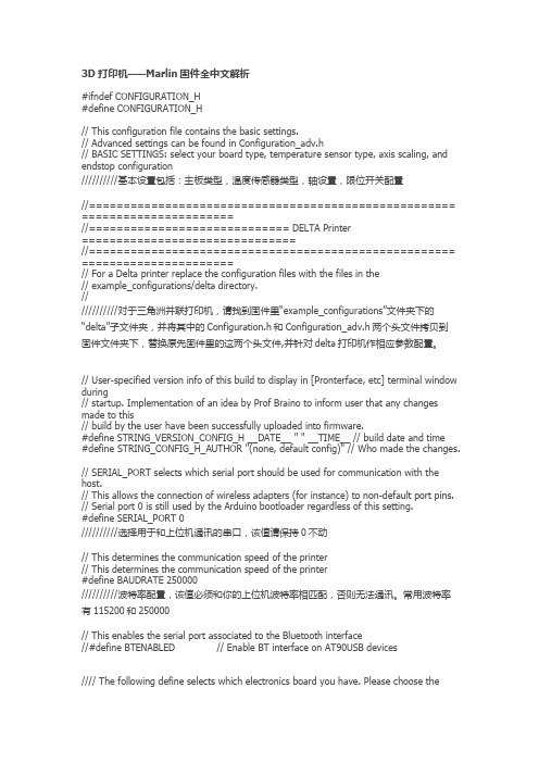
3D打印机——Marlin固件全中文解析#ifndef CONFIGURATION_H#define CONFIGURATION_H// This configuration file contains the basic settings.// Advanced settings can be found in Configuration_adv.h// BASIC SETTINGS: select your board type, temperature sensor type, axis scaling, and endstop configuration//////////基本设置包括:主板类型,温度传感器类型,轴设置,限位开关配置//===================================================== ======================//============================= DELTA Printer===============================//===================================================== ======================// For a Delta printer replace the configuration files with the files in the// example_configurations/delta directory.////////////对于三角洲并联打印机,请找到固件里“example_configurations”文件夹下的“delta”子文件夹,并将其中的Configuration.h和Configuration_adv.h两个头文件拷贝到固件文件夹下,替换原先固件里的这两个头文件,并针对delta打印机作相应参数配置。
曼氏无针乌贼肌肉cDNA文库的构建和表达序列标签分析
中 图 分 类 号 : 18 5 Q 7 .3
文献标识码 : A
文 章 编 号 :0 08 6 ( 0 )30 5 -6 10 —10 2 1 0 -37
湾
海
峡
Vo . 0. No 13 .3 Aug .,2 011
21 0 1年 8月
J OURNA O O EANOGR HY N AI AN T I L F C AP I T W S RA T
曼 氏无 针 乌贼 肌 肉 c N D A文 库 的 构 建 和 表 达 序 列 标 签 分 析
1 2 方 法 .
质资 源退 化 , 出现 个体 小 、 性早 熟 和 白化 卵 等问题 . 构建 S s 的分 析 , 其 功 能 进 行 推 ET ) 对
蒋霞敏 , 王 佳 , 良义 , 薛 曾建 刚
( 宁波大学生命科学与生物工 程学院 , 江 宁波 3 5 1 ) 浙 12 1
摘要: 以曼氏无针乌贼(eil m i r i肌 肉组织为研 究材料 , S ea an o ) p l d n 利用 Cot h cN
技术 的 发展 。 , 量人 工养 殖造 成 曼 氏无 针 乌贼 种 。 大
实验 乌贼 肌 肉组 织采 自浙江省 舟 山市六 横 海 区
野生 成 体 曼 氏无 针 乌 贼 (eil an rn) 提 取 Speam i oi. l d R A所用 Ti l 剂购 于上 海生 工生 物工 程有 限公 N ro 试 z 司. 建 c N 构 D A文 库 所 用 试 剂 盒 购 于 Co c leh公 司. t cN D A纯 化 柱 购 于 P am c hr ai 司. 肠 杆 菌 J 0 a公 大 M19 购 于 TK R a a a公 司. 他 常规试 剂 均为 国产 分析 纯 . 其
FURUNO CSH-53R Color Scanning Sonar 产品说明书

CSH-531.DisplayHigh-resolution 15-inch CRT, 640 (H) x 480 (V) dots 2.Presentation ColorEchoes in 16 colors, Marks in 4 colors 3.Frequency28 or 50 kHz (specify when ordering)4.Presentation ModesFull-circle, Full-circle+E/S combination, and Full-circle+Historical Display in Head-up, North-up* and True Motion**Appropriate sensors required 5.Range Scales50 kHz model:75 - 2,000 m (3,200 m in Off-center)28 kHz model:75 - 3,000 m (4,800 m in Off-center)6.Pulselength Pulselength:0.5 to 20 ms (depending on range scales)7.Beamwidth (at -6 dB)50 KHz 28 kHzTX:360°(hor) x 13°- 16°(ver)360°x 21°- 25°RX:16°- 22°(hor) x 13°- 18°(ver)25°- 23°8.TiltManual control:-5°to 60°(downward) in 1°steps Automatic tilt scan:2°steps 9.Hull UnitTravel:800 mm 1200 mm Raising Time:16 seconds 22 seconds Lowering Time:15 seconds 20 seconds Ship Speed:18 knots 18 knots (Raise/Lower):(15 knots)(15 knots)10.Audio Search30°, 60°, 90°, 180°, 330°Audio Output: 2 W, Frequency: 1.1 kHzPOWER SUPPLYq 100 VAC, 50/60 Hz, 1ø, 500 VA (1 kVA max)q 115/230 VAC with optional stepdown transformer PT-400q24/32 VDC with optional DC-AC inverters TR-2435 and TR-24100EQUIPMENT LIST (specify 28 or 50 kHz)Standard1.Display Unit CSH-5302.Transmitter Unit CSH-5513.Receiver Unit CSH-5524.Hull Unit (specify when ordering)CSH-5508F (800 mm travel)CSH-5512 (1200 mm travel)5.Remote Controller CSH-1356.Interface Unit CS-120A7.Installation materials and spare partsOptional1.DC-AC Inverter TR-2435 and TR-24100 for 24 VDC2.Stepdown Transformer PT-400 Sonde Interface CS-1704.Echo Sounder Interface VI-1100A5.Sub-Display Unit CSH-5366.Remote Display Unit CSH-1067.Gyro Converter AD-1008.Hand Grip9910XN Printed in JapanSPECIFICATIONS SUBJECT TO CHANGE WITHOUTFURUNO U.S.A., INC.Camas, Washington, U.S.A.Phone: +1 415-360-834-9300 Telefax: +1 360-834-9400FURUNO (UK) LIMITED Denmead, Hampshire, U.K.Phone: +44 2392-230303 Telefax: +44 2392-230101FURUNO FRANCE S.A.Bordeaux-Mérignac, FrancePhone: +33 5 56 13 48 00 Telefax: +33 5 56 13 48 01FURUNO ESPANA S.A.Madrid, SpainPhone: +34 1-435-95-20 Telefax: +34 1-431-30-82FURUNO DANMARK AS Hvidovre, DenmarkPhone: +45 36 77 45 00 Telefax: +45 36 77 45 01FURUNO NORGE A/S Ålesund, NorwayPhone: +47 70 102950 Telefax: +47 70 127021FURUNO SVERIGE AB Västra Frölunda, SwedenPhone: +46 31-7098940 Telefax: +46 31-497093FURUNO SUOMI OY Helsinki, FinlandPhone: +358 9 317277 Telefax: +358 9 3412930。
一种基于活塞连续工作原理的3D食品打印笔
一种基于活塞连续工作原理的3D食品打印笔
王金磊;王晓军;任衍涛
【期刊名称】《食品与机械》
【年(卷),期】2015(031)005
【摘要】介绍一种基于活塞连续工作原理的3D打印笔的结构特点以及主要工作原理,并建立系统的数学模型.与以往的3D打印笔相比,其打印材料由ABS等塑性材料变成如液态巧克力等液态材料,使得打印材料范围得到扩展,并且设计合理,使用方便,有助于其它3D打印笔的研发与设计.
【总页数】3页(P136-138)
【作者】王金磊;王晓军;任衍涛
【作者单位】浙江大学宁波理工学院机电与能源工程学院,浙江宁波 315100;太原科技大学机械工程学院,山西太原 030024;浙江大学宁波理工学院机电与能源工程学院,浙江宁波 315100;浙江省零件轧制成形技术重点实验室,浙江宁波 315100;浙江大学宁波理工学院机电与能源工程学院,浙江宁波 315100;太原科技大学机械工程学院,山西太原 030024
【正文语种】中文
【相关文献】
1.一种气动活塞式3D巧克力打印头设计 [J], 孔楚海
2.浅析现代科技条件下食品行业中的快食品与慢生活——基于食品3D打印新技术的思考 [J], 刁生富;汤璐
3.基于活塞挤出式3D打印制备PLA/n-HA生物支架 [J], 王波群;揭晓华;胡晓岳
4.基于活塞挤出式3D打印制备PLA/PCL生物支架的研究 [J], 王波群;揭晓华
5.基于食品3D打印技术的食品原料研究及应用 [J], 杨庆余;王妍文;李响;张依睿;吕春月;罗志刚;肖志刚
因版权原因,仅展示原文概要,查看原文内容请购买。
赛米控CM2006-D LCD和摄像头EMI滤波器阵列 使用手册说明书

CM2006Praetorian) L-C LCD and Camera EMI Filter Array with ESD ProtectionProduct DescriptionThe CM2006 connects between the VGA or DVI−I port connector and the internal analog or digital flat panel controller logic. The CM2006 incorporates ESD protection for all signals, level shifting for the DDC signals and buffering for the SYNC signals. ESD protection for the video, DDC and SYNC lines is implemented with low−capacitance current steering diodes.All connector interface pins are designed to safely handle the high current spikes specified by IEC−61000−4−2 Level 4 (±8 kV contact discharge). The ESD protection for the DDC, SYNC and VIDEO signal pins is designed to prevent “backdrive current” when the device is powered down while connected to a video source that is powered up. Separate positive supply rails are provided for the VIDEO / SYNC signals and DDC signals to facilitate interfacing with low voltage video controller ICs and microcontrollers to provide design flexibility in multi−supply−voltage environments.Two Schmitt−triggered non−inverting buffers redrive and condition the HSYNC and VSYNC signals from the video connector (SYNC1, SYNC2). These buffers accept VESA VSIS compliant TTL input signals and convert them to CMOS output levels that swing between ground and V CC.Two N−channel MOSFETs provide the level shifting function required when the DDC controller or EDID EEPROM is operated at a lower supply voltage than the monitor. The gate terminals for these MOSFETS (V CC_DDC) should be connected to the supply rail (typically 3.3 V, 2.5 V, etc.) that supplies power to the transceivers of the DDC controller.Features•Includes ESD Protection, Level−Shifting, Buffering and Sync Impedance Matching•VESA VSIS Version 1 Revision 2 Compatible Interface•Supports Optional NA VI Signalling Requirements •7 Channels of ESD Protection for all VGA Port Connector Pins. All Pins Meet IEC−61000−4−2 Level 4 ESD Requirements (±8 kV Contact Discharge)•Very Low Loading Capacitance from ESD Protection Diodes on VIDEO Lines (3 pF Maximum)•Schmitt−Triggered Input Buffers for HSYNC and VSYNC Lines •Bidirectional Level Shifting N−Channel FETs Provided for DDC_CLK & DDC_DATA Channels •Backdrive Protection on all Lines•Compact 16−Lead QSOP Package•These Devices are Pb−Free and are RoHS Compliant Applications•VGA and DVI−I Ports in:♦Monitors♦TVsMARKING DIAGRAMDevice Package Shipping†ORDERING INFORMATIONCM2006−02QR QSOP−16(Pb−Free)2500/T ape & ReelQSOP16QR SUFFIXCASE 492†For information on tape and reel specifications, including part orientation and tape sizes, please refer to our Tape and Reel Packaging SpecificationBrochure, BRD8011/D.CM2006−02QR= Specific Device CodeYY= YearWW= Work WeekCMDYYWWCM200602QRELECTRICAL SCHEMATICVIDEO_1VIDEO_2VIDEO_3GNDSYNC_OUT2V CC_DDCV CCSYNC_OUT1SYNC_IN2SYNC_IN1DDC_IN2DDC_IN1DDC_OUT2DDC_OUT1BYPENABLE PACKAGE / PINOUT DIAGRAMTop ViewV CC ENABLE VIDEO_1VIDEO_2VIDEO_3GND V CC_DDCBYPSYNC_IN2SYNC_OUT1SYNC_OUT2SYNC_IN1DDC_IN2DDC_OUT2DDC_OUT1DDC_IN1Table 1. PIN DESCRIPTIONSLead(s)Name Description1V CC This is a supply input for the SYNC_1 and SYNC_2 level shifters, video protection and the DDC circuits.2ENABLE Active high enable. Disables the Sync buffer outputs when low.3VIDEO_1Video signal ESD protection channel. This pin is typically tied one of the video lines between the control-ler device and the video connector.4VIDEO_2Video signal ESD protection channel. This pin is typically tied one of the video lines between the control-ler device and the video connector.5VIDEO_3Video signal ESD protection channel. This pin is typically tied one of the video lines between the control-ler device and the video connector.6GND Ground reference supply pin.7V CC_DDC This is an isolated supply input for the DDC_1 and DDC_2 level−shifting N−FET gates.8BYP An external 0.22 m F bypass capacitor is required on this pin.9DDC_IN1DDC signal input. Connects to the video connector side of one of the DDC lines.signal output.10DDC_OUT1DDC signal output. Connects to the monitor DDC logic.11DDC_OUT DDC signal output. Connects to the monitor DDC logic.12DDC_IN2DDC signal input. Connects to the video connector side of one of the DDC lines 13SYNC_IN1Sync signal buffer input. Connects to the video connector side of one of the sync lines.14SYNC_OUT1Sync signal buffer output. Connects to the monitor SYNC logic.15SYNC_IN2Sync signal buffer input. Connects to the video connector side of one of the sync lines.16SYNC_OUT2Sync signal buffer output. Connects to the monitor SYNC logic.SPECIFICATIONSTable 2. ABSOLUTE MAXIMUM RATINGSParameter Rating Units V CC_DDC and V CC Supply Voltage Inputs[GND − 0.5] to +6.0V DC Voltage at InputsVIDEO_1, VIDEO_2, VIDEO_3 DDC_IN1, DDC_IN2DDC_OUT1, DDC_OUT2SYNC_IN1, SYNC_IN2, ENABLE [GND − 0.5] to [V CC + 0.5][GND − 0.5] to 6.0[GND − 0.5] to 6.0[GND − 0.5] to [V CC + 0.5]VOperating Temperature Range−40 to +85°C Storage Temperature Range−40 to +150°C Package Power Rating (T A = 25°C)500mW Stresses exceeding those listed in the Maximum Ratings table may damage the device. If any of these limits are exceeded, device functionality should not be assumed, damage may occur and reliability may be affected.Table 3. STANDARD OPERATING CONDITIONSParameter Rating Units Operating Temperature Range−40 to +85°CV CC5V Functional operation above the stresses listed in the Recommended Operating Ranges is not implied. Extended exposure to stresses beyond the Recommended Operating Ranges limits may affect device reliability.Table 4. ELECTRICAL OPERATING CHARACTERISTICS (Note 1)Symbol Parameter Conditions Min Typ Max Units I CC_DDC V CC_DDC Supply Current V CC_DDC = 5.0 V10m AI CC V CC Supply Current V CC = 5 V; SYNC inputs at GND or V CC;SYNC outputs unloaded1mAV CC = 5 V; SYNC inputs at 3.0 V;SYNC outputs unloaded2.0mAV F ESD Diode Forward Voltage I F = 10 mA 1.0V V IH Logic High Input Voltage V CC = 5.0 V; (Note 2) 2.0V V IL Logic Low Input Voltage V CC = 5.0 V; (Note 2)0.5V V HYS Hysteresis Voltage V CC = 5.0 V; (Note 2)400mV V OH Logic High Output Voltage I OH = 0 mA, V CC = 5.0 V; (Note 2) 4.0V V OL Logic Low Output Voltage I OL = 0 mA, V CC = 5.0 V; (Note 2)0.15V R OUT SYNC Driver Output Resistance V CC = 5.0 V; SYNC Inputs at GND or 3.0 V71524WI IN Input CurrentVIDEO Inputs V CC = 5.0 V; V IN= V CC or GND±10m ASYNC_IN1, SYNC_IN2 Inputs V CC = 5.0 V; V IN= V CC or GND±10m AI OFF Level Shifting N−MOSFET “OFF” StateLeakage Current (V CC_DDC− V DDC_IN) < 0.4 V;V DDC_OUT= V CC_DDC10m A(V CC_DDC− V DDC_OUT) < 0.4 V;V DDC_IN= V CC_DDC10m AI BACKDRIVE Current conducted from input pins whenVcc is powered down.V CC < V INPUT_PIN; (Note 5)10m AV ON Voltage Drop Across Level−shiftingN−MOSFET when ”ON”V CC_DDC = 2.5 V; V S = GND; I DS = 3 mA0.18VC IN_VID VIDEO Input Capacitance V CC = 5.0 V; V IN= 2.5 V; f= 1 MHz3pFV CC = 2.5 V; V IN= 1.25 V; f= 1 MHz 3.5pF t PLH SYNC Driver L => H Propagation Delay C L = 50 pF; V CC= 5.0 V; Input t R and t F< 5 ns12ns t PHL SYNC Driver H => L Propagation Delay C L = 50 pF; V CC= 5.0 V; Input t R and t F< 5 ns12ns t R,t F SYNC Driver Output Rise & Fall Times C L = 50 pF; V CC= 5.0 V; Input t R and t F< 5 ns3ns V ESD1ESD Withstand Voltage, Sync_out pinsonlyV CC = 5 V; (Notes 3 and 4)±2kV V ESD ESD Withstand Voltage V CC = 5 V; (Notes 3 and 5)±8kVProduct parametric performance is indicated in the Electrical Characteristics for the listed test conditions, unless otherwise noted. Product performance may not be indicated by the Electrical Characteristics if operated under different conditions.1.All parameters specified over standard operating conditions unless otherwise noted.2.These parameters apply only to the SYNC drivers. Note that R OUT = R T + R BUFFER.3.Per the IEC−61000−4−2 International ESD Standard, Level 4 contact discharge method. BYP and V CC must be bypassed to GND via a lowimpedance ground plane with a 0.22 m F, low inductance, chip ceramic capacitor at each supply pin. ESD pulse is applied between the applicable pins and GND. ESD pulses can be positive or negative with respect to GND. Applicable pins are: VIDEO_1, VIDEO_2, VIDEO_3, SYNC_IN1, SYNC_IN2, DDC_IN1 and DDC_IN2. All pins are ESD protected to the industry standard ±2 kV Human Body Model (MIL−STD−883, Method 3015).4.This specification applies to the SYNC_OUT pins only.5.Applicable pins are: VIDEO_1, VIDEO_2, VIDEO_3, SYNC_IN1, SYNC_IN2, DDC_IN1 and DDC_IN2.APPLICATION INFORMATIONFigure 1. Typical Application Connection DiagramNOTES:1.The CM2006 should be placed as close to the VGA or DVI−I connector as possible.2.The ESD protection channels VIDEO_1, VIDEO_2, VIDEO_3 may be used interchangeably between the R, G, Bsignals.3.If differential video signal routing is used, the RED, BLUE, and GREEN signal lines should be terminated withexternal 37.5 W resistors.4.“VF” are external video filters for the RGB signals.5.Supply bypass capacitors C1 and C2 must be placed immediately adjacent to the corresponding Vcc pins.Connections to the Vcc pins and ground plane must be made with minimal length copper traces (preferably less than5 mm) for best ESD protection.6.The bypass capacitor for the BYP pin has been omitted in this diagram. This results in a reduction in the maximumESD withstand voltage at the DDC_OUT pins from ±8 kV to ±2 kV. If 8 kV ESD protection is required, a 0.22 m F ceramic bypass capacitor should be connected between BYP and ground.7.The SYNC buffers may be used interchangeably between HSYNC and VSYNC.8.The EMI filters at the SYNC_OUT and DDC_OUT pins (C5 to C12, and Ferrite Beads FB1 to FB4) are for referenceonly. The component values and filter configuration may be changed to suit the application.9.The DDC level shifters DDC_IN, DDC_OUT, may be used interchangeably between DDCA_CLK andDDCA_DA TA.10.R1, R2 are optional. They may be used, if required, to pull the DDC_CLK and DDC_DATA lines to VCC_5V whenno VGA card is connected to the VGA monitor. If used, it should be noted that “back current” may flow between the DDC pins and VCC_5V via these resistors when VCC_5V is powered down.Praetorian® is a registered trademark of Semiconductor Components Industries, LLC.QSOP16CASE 492−01ISSUE ADATE 23 MAR 2011DIM MAX MIN INCHES A 0.0530.069b 0.0080.012L 0.0160.050e 0.025 BSC h 0.0090.020c 0.0070.010A10.0040.010M0 8 NOTES:1.DIMENSIONING AND TOLERANCING PER ASME Y14.5M, 1994.2.CONTROLLING DIMENSION: MILLIMETERS.3.DIMENSION b DOES NOT INCLUDE DAMBAR PROTRUSION.4.DIMENSION D DOES NOT INCLUDE MOLD FLASH,PROTRUSIONS, OR GATE BURRS. MOLD FLASH,PROTRUSIONS, OR GATE BURRS SHALL NOT EXCEED 0.005 PER SIDE. DIMENSION E1 DOES NOT INCLUDE INTERLEAD FLASH OR PROTRUSION. INTERLEAD FLASH OR PROTRUSION SHALL NOT EXCEED 0.005 PER SIDE. D AND E1 ARE DETERMINED AT DATUM H.5.DATUMS A AND B ARE DETERMINED AT DATUM H.__DIMENSIONS: MILLIMETERSSOLDERING FOOTPRINTSEATING PLANEXXXXX = Specific Device Code YY = YearWW = Work WeekG = Pb −Free PackageGENERICMARKING DIAGRAM**This information is generic. Please refer to device data sheet for actual part marking. Pb −Free indicator, “G”, may or not be present.D 0.193 BSCE 0.237 BSC E10.154 BSC L20.010 BSC XXXXXXX XXXXXXX YYWWGA20.049---- 1.35 1.750.200.300.40 1.270.635 BSC 0.220.500.190.250.100.250 8 __4.89 BSC 6.00 BSC 3.90 BSC 0.25 BSC 1.24----MAX MIN MILLIMETERSMECHANICAL CASE OUTLINEPACKAGE DIMENSIONSON Semiconductor and are trademarks of Semiconductor Components Industries, LLC dba ON Semiconductor or its subsidiaries in the United States and/or other countries.ON Semiconductor reserves the right to make changes without further notice to any products herein. ON Semiconductor makes no warranty, representation or guarantee regarding the suitability of its products for any particular purpose, nor does ON Semiconductor assume any liability arising out of the application or use of any product or circuit, and specifically disclaims any and all liability, including without limitation special, consequential or incidental damages. ON Semiconductor does not convey any license under its patent rights nor thePUBLICATION ORDERING INFORMATIONTECHNICAL SUPPORTNorth American Technical Support:Voice Mail: 1 800−282−9855 Toll Free USA/Canada Phone: 011 421 33 790 2910LITERATURE FULFILLMENT :Email Requests to:*******************onsemi Website: Europe, Middle East and Africa Technical Support:Phone: 00421 33 790 2910For additional information, please contact your local Sales Representative。
自己做一台3D打印机到底有多难?(附教程)
⾃⼰做⼀台3D打印机到底有多难?(附教程)• 微博:⼩样⼉⽼师2015• 简书:⼩样⼉⽼师初识3D打印技术,即快速成形技术,它是⼀种以数字模型⽂件为基础,运⽤粉末状⾦属或塑料等可粘合材料,通过逐层打印的⽅式来构造物体的技术,3D打印机则出现在上世纪90年代中期,即⼀种利⽤光固化和纸层叠等技术的快速成型装置。
它与普通打印机⼯作原理基本相同,打印机内装有液体或粉末等“印材料”,与电脑连接后,通过电脑控制把“打印材料”⼀层层叠加起来,最终把计算机上的蓝图变成实物。
如今这⼀技术在多个领域得到应⽤,⼈们⽤它来制造服装、建筑模型、汽车、巧克⼒甜品等。
技术原理⾯向普通⽤户的桌⾯级3D打印使⽤的是融融挤压式技术(FDM),在描绘融融挤压式3D打印机的⼯作原理之前,我们可以先设想这样⼀个场景:⾸先你拿着⼀根被加热过的⽛膏,在⽛膏盒⾥⾯都是液态的,但只要你把它⼀挤出来就会马上凝固;然后你把这根⽛膏头朝下拿着,并往桌⼦上挤,边挤边⽔平移动,就像写⽑笔字⼀样;等你完成桌⾯上⼀层的⼯作后,把⽛膏再往上抬⼀点,接着往第⼆个平⾯上继续挤⽛膏,这时挤压出来的⽛膏会和之前的⽛膏粘在⼀起,先挤出来的⽛膏会固化形成后⾯挤出⽛膏的⽀撑,最后你不断地重复以上过程,直到挤出你想要的形状,这其实就是FDM的基本思想。
根据这样的基本思想,将原材料预先加⼯成特定⼝径的圆形线材,然后将这种线型材料进⾏热熔化处理,通过挤压将融化成液态的材料挤喷出来,通过电脑程序控制喷嘴的坐标移动即可实现实物的3D打印。
开源3D打印机REPRAP发展史REPRAP开源项⽬是由英国巴斯⼤学(the University of Bath) Adrian Bowyer 等⼈所发起,主要⽬的是希望能够独⽴设计和制作出⼀款⾯向所有普通⽤户的3D打印机。
经过多年发展能⽤的版本有三个。
第⼀代产品称为Darwin(达尔⽂)第⼆代产品称为Mendel(孟德尔)第三代产品称为Prusa(普鲁⼠)如何制作⼀台3D打印机接下来说重点,如何制作开源3D打印机REPRAP的第三代产品。
纹理采样[发明专利]
![纹理采样[发明专利]](https://img.taocdn.com/s3/m/6e202e2c6137ee06eef9181c.png)
专利名称:纹理采样
专利类型:发明专利
发明人:U·萨雷,P·罗森菲尔德申请号:CN201010220862.7申请日:20100629
公开号:CN101937556A
公开日:
20110105
专利内容由知识产权出版社提供
摘要:使用着色语言来实现纹理采样器。
着色器编译器用于基于提供给纹理采样器的采样器状态、采样器操作以及其它静态要素输入值将纹理采样器编译为目标机器。
当调用着色器时,诸如顶点着色器、几何着色器、像素着色器、外壳着色器、域着色器和计算着色器这样的着色器可以调用一个或多个纹理采样器。
作为一段软件代码的一个或多个纹理采样器可以根据纹理数据生成纹理采样,并且将这种纹理采样提供给着色器。
着色器使用纹理采样在图形元素上生成着色效果。
然后,将图形元素连同着色效果渲染在显示设备上。
申请人:英特尔公司
地址:美国加利福尼亚
国籍:US
代理机构:永新专利商标代理有限公司
更多信息请下载全文后查看。
牛瑟氏泰勒虫表面蛋白p33基因的真核表达

p VAX Ia dta se td Heac l.Reut RT P R h w dta 3 e ewa f cieyta sr e .I A e n n fce l e1 r sl s . C s o e h t7 3 gn se e t l rn c b d F d m— I v i
根据 已发表 的牛瑟 氏泰 勒虫( e— i
l i sr ni表面蛋白 p 3基因的核苷酸序列设计 引物 , 用 P R技术从牛瑟氏泰勒虫基 因组 D A中扩增 p3基 e a e et r g ) 3 应 C N 3
因片段并克隆入 p 1一 ipe MD 8Ts l 载体 。进一步将 该基 因插入到真核表达 载体 p A 转 染 H l m V XI, e a细胞后进行 R — T P R检测和 IA检测。结果 C F
T elra sr e t nd wa ln d i t MD1 T smp e v co ,t e si s re n o e ay tc e p e so e tr h i i eg nia s co e no p e 8一 i l e t r h n wa n e td i t uk r oi x r sin v c o
o srt d ta h g n s e p e s d n e ay t e1 Con l i n T e e u t sa ls e a e fr f rh r n tae h tt e e e wa x r s e i uk r oi c l. c cuso h rs ls e tb ih d a b s o u t e su y o h u ci n o 3 e e fo T elra sr ni td n t e f n to fp 3 g n m h i i ege t. r e
TE Connectivity 公司 Pro-Crimper III 手动压紧工具集装箱 79016

©2011 Tyco Electronics Corporation, a TE Connectivity Ltd. Company All Rights Reserved 1 of 5Instruction SheetTOOLING ASSISTANCE CENTER 1-800-722-1111PRODUCT INFORMATION 1-800-522-6752This controlled document is subject to change.For latest revision and Regional Customer Service,PRO-CRIMPER* III Hand Crimping Tool Assembly 790163-[ ]408-873810 MAY 11 Rev MPROPER USE GUIDELINESCumulative Trauma Disorders can result from the prolonged use of manually powered hand tools. Hand tools are intended for occasional use and low volume applications. A wide selection of powered application equipment for extended-use, production operations is available.Figure 11. INTRODUCTIONPRO-CRIMPER III Hand Crimping Tool Assembly 790163-[ ] consists of PRO-CRIMPER III Hand Tool Frame 354940-1 and Die Assemblies listed in Figure 1.The tool assembly is used to crimp the contacts, and the internal and external strain reliefs of the modular plugs listed in Figure 1.Read these instructions thoroughly before using the hand tool assembly.Dimensions in this instruction sheet are in millimeters. Figures and illustrations are for reference only and are not drawn to scale.Reasons for reissue of this instruction sheet are provided in Section 8, REVISION SUMMARY .2. DESCRIPTIONThe tool frame features a stationary jaw and handle, a moving jaw and handle, and an adjustable ratchet thatPRO-CRIMPER III hand crimping tool is a ?Commercial" grade and is designed primarily for field installation, repair, maintenance work, and prototyping in industrial, commercial, and institutional applications. Productcrimped with this tool will meet the crimp heightrequirement for hand tools in the appropriate application specification (114-series), but may not comply with otherfeature parameters of the document. A variety of tools areoffered to satisfy performance requirements. ForDie Assembly Moving Jaw Stationary Handle Pivot PinRatchet Adjustment WheelMoving HandleBack of Tool Stationary JawPRO-CRIMPER III Hand Crimping Tool Frame 354940-1TE Hand Tool TE Die Assembly Modular Plug •CABLESize (AWGConductor Insulation Diameter (mm)Outside Diameter (mm)Strip Length (mm)790163-1790163-2336330-1, -226-240.80-1.005.0-6.035.0+5.0790163-3790163-4336349-1 5.0-6.0790163-5790163-6336462-1 6.0-7.0790163-7790163-81711413-1, -226-240.80-1.00 4.7-5.31933441-[ ]26-240.89-1.091933442-[ ]24-230.89-1.09790163-91-790163-01933433-[ ]1499598-[ ]28-221.12-1.227.0-7.930.0+5.0• For additional modular plug part numbers, contact PRODUCT INFORMATION at the bottom of this page.NOTEiensures full crimping. The tool frame holds the die assembly. Refer to Figure 1.The die assembly consists of an insulation stuffer, wire stuffer, housing support, housing guides, and mounting and retaining hardware.3. INSTALLATION AND REMOVAL OF DIE ASSEMBLY1. Close the tool handles until the ratchet releases,then allow the handles to open fully. If present,remove both retaining screws from the tool frame.2. Orient the insulation stuffer as shown in Figure 2,and insert it into the stationary jaw of the tool frame.Align the holes with the associated holes in the tool frame. Insert the short retaining pins and shortretaining screw into the holes in the tool frame.Tighten the screw.3. Orient the housing support as shown in Figure 2,and insert it into the moving jaw of the tool frame.Align the holes with the associated holes in the tool frame. Orient the right housing guide as shown, and mount it onto the tool frame using the long retaining pins. Insert the long retaining screw through thehole in the right housing guide. Tighten the screw.4. Refer to Figure 2. Orient the left housing guide asshown, and secure it onto the tool frame using the tension adjusting nut. Tighten the tension adjusting nut using an assembled modular plug connectorassembly.Adjust the tension adjusting nut to allow theassembly to fit (snugly).5. Carefully close the tool handles, making sure thatthe parts align properly.6. To disassemble, close the tool handles until theratchet releases. Remove the nut, screws, housing guides, retaining pins, housing support, andinsulation stuffer out of the tool frame jaws.4. CRIMPING PROCEDUREBefore proceeding, refer to the applicable Application Specification: 114-22008 (Category 5e EMT) or 114-13035 and 114-93006 (Category 6 shielded), and ensure the following:•the modular plug and cable are compatible •the cable polarity is properly maintained•the modular plug is properly crimped andassembledMake sure that the modular plug shield is fullybottomed onto the body. With some cablescontaining shielded twisted pairs, this is especiallyIMPORTANT to check.1. Close the tool handles until the ratchet releases,then allow the handles to open FULLY.2. Hold the tool so that the back is facing you. Insertthe modular plug (including shield and cable) in the crimping chamber until it bottoms. Refer to Figure 3.Figure 2NOTE iCAUTION! Tension AdjustingNutLeft Housing GuideInsulation StufferWire Stuffer (Ref) Socket Head Cap Screw(Retains Wire Stuffer, Ref)Short RetainingScrewTool FrameLong Retaining Pin(2 Places)Short Retaining Pin(2 Places)Long RetainingScrewRight Housing GuideHousing SupportFigure 33. While holding the assembly, carefully close the tool handles until the ratchet releases, then allow the handles to open FULLY.This tool terminates 3 areas of the modular plug.For proper alignment, make sure to apply forwardpressure on the cable while closing the toolhandles.4. Remove the modular plug from the tool, and make sure that the crimp requirements are met according to the applicable application specification (refer to first paragraph of Section 4).If necessary, adjust the tool ratchet according to Paragraph 5.1 to obtain the proper crimp height.Figure 4Crimp Height Gage 904170-1 is to be used as aquick verification of acceptable crimp height asshown in Figure 4. Refer to Instruction Sheet 408-4389 for instructions on using the gage.5. ADJUSTMENTS5.1. Ratchet Adjustment (Figure 5)The tool ratchet mechanism features an adjustment wheel with numbered settings. The adjustment wheel controls the amount of handle pressure exerted on the jaws during crimping. If the crimp is not acceptable, adjust the ratchet as follows:1. Remove the lockscrew from the ratchetadjustment wheel.2. With a screwdriver, adjust the ratchet wheel fromthe front of the tool.3. Observe the ratchet adjustment wheel. If a tightercrimp is required, rotate the adjustment wheelcounterclockwise to a higher-numbered setting. If a looser crimp is required, rotate the adjustmentwheel clockwise to a lower-numbered setting.4. Re-assemble the lockscrew.5. Make a sample crimp. If the crimp is acceptable,the adjustment setting is correct. If the crimp isunacceptable, continue to adjust the ratchet, and again measure a sample crimp. If a proper crimp cannot be obtained, the tool or die assembly must be replaced. Refer to Section 7.The tool is set at the No. 7 ratchet setting at thefactory. This setting assures the proper crimpheight for solid wire and accounts for the maximumtolerance in the tooling. You can readjust your toolto a lower setting, (No. 4, minimum), as long asyou achieve the proper insertion depth, 6.02 ± .13[.237 ± .005). See the applicable applicationspecification5.2. Wire Stuffer AdjustmentIf the wire stuffer is not assembled onto the insulation stuffer or if correct alignment of these two parts is unsure, proceed with the following:1. Install the wire stuffer onto the insulation stufferusing the 4-40 UNC.621 in. socket head cap screw included with the die assembly. Refer to Figure 2.DO NOT tighten the screw. If the screw is tight,loosen it.2. Close the tool handles until the ratchet releases,then allow the handles to open FULLY. Insert amodular plug (without cable) into the crimpingchamber.3. Close the tool handles, and hold.4. Insert a key into the socket head cap screw(retaining the wire stuffer), and tighten the screw.Wire StufferInsulationStufferHousing SupportModular Plug Bottomedin Crimping ChamberNOTEiModular Plug (Ref)Crimp Height Gage(Ref) Checking Crimp HeightNOTE i NOTE iNOTE iFigure 55. Allow the handles to open, and remove thecrimped modular plug. The wire stuffer will be held in its proper position.6. MAINTENANCE AND INSPECTION6.1. Daily MaintenanceIt is recommended that the tool operator be made aware of, and are responsible for, the following steps of daily maintenance.1. Remove dust, moisture, and any othercontaminants from the tool with a clean, soft brush, or a clean, soft, lint-free cloth. DO NOT use hard or abrasive objects that could damage the tool.2. Make certain that the retaining pins are in placeand that they are secured with retaining rings.3. All pins, pivot points, and bearing surfaces shouldbe protected with a thin coat of any good gradeSAE* 20 motor oil. DO NOT oil excessively.When the tool is not in use, keep the handles closed toprevent objects from becoming lodged in the jaws.4. Store the tool in a clean, dry area.6.2. Periodic InspectionRegular inspection of the tool should be performed by quality control personnel. A record of the scheduled inspections should remain with the tool or be supplied to personnel responsible for the tool. Inspection frequency should be based on amount of use, working conditions, operator training and skill, and established company standards.6.3. Visual Inspection1. Remove all lubrication and accumulated film byimmersing the tool (handles partially closed) in a suitable commercial degreaser that will NOT affect paint or plastic material.2. Make certain that the retaining pins are in placeand that they are secured with retaining rings.3. Close the tool handles until the ratchet releases,and then allow the handles to open freely. If they do not open quickly and fully, the spring is defective and must be replaced.4. Inspect the tool frame for wear or damage,paying particular attention to the tool jaws and the pivot points. If damage is evident, replace it. Ifdamage is not evident, lubricate the pivot point and return the tool to service.5. Check the die assembly on a regular basis toensure it has not become worn or damaged. Inspect the crimping sections for flattened, chipped, worn, or broken areas. If damage is evident, replace the die assembly.7. REPLACEMENTCustomer-replaceable parts are shown in Figure 1. Available separately, PRO-CRIMPER III Hand Tool Repair Kit 679221-1 includes a replacement nut and a variety of pins, rings, screws, and springs. If the die assembly is damaged or worn excessively, it must be replaced. Order the repair kit and replaceable parts through your representative, or call 1-800-526-5142, or send a facsimile of your purchase order to 717-986-7605, or write to:CUSTOMER SERVICE (038-035)TYCO ELECTRONICS CORPORATIONPO BOX 3608HARRISBURG PA 17105-36088. REVISION SUMMARYSince the previous release, a ratchet adjustment note was added in Section 5.Screwdriver RatchetAdjustmentWheelLockscrew * SAE is a trademark.PRO-CRIMPER III Hand Tool Frame 354940-1(Instruction Sheet 408-9930)SDE-SA Hand Tool 9-1478240-0(Instruction Sheet 408-8851)SDE Bench Terminator 1490076-2(Customer Manual 409-10052)626 Adapter 679304-1(Instruction Sheet 408-4070)“C”-Head Assembly 2031450-1Closed Head Assembly 2031460-1Tooling Used with Dies 1790163-0。
富士施乐DocuCentre 2060 3060 3065 复印机维修手册:dc3060g_sc_ver1_chap05

第五章零件表2011/075-1DocuCentre-IV 3060G零件表Version 1.05 零件表5.1 序文5.1.1 零件表的使用方法.....................................................35.1.2 使用零件表的注意事项.................................................35.1.3 Plate 的构成.........................................................45.1.4 术语·符号的说明.....................................................45.1.5 零件向导的使用方法...................................................55.2 Parts List 1. IIT/UIPL 1.1 Platen/IIT Cover....................................................7PL 1.2 CCD Lens Assenbly/Platen Glass......................................8PL 1.3 Full/Half Rate Carriage/Carriage Cable..............................9PL 1.4 Full Rate Carriage..................................................10PL 1.5 Half Rate Carriage..................................................11PL 1.6 Motor/Transport PWB.................................................12PL 1.7 W70 Control Panel...................................................13PL 1.8 Option..............................................................142. ROSPL 2.1 ROS.................................................................153. DRIVEPL 3.1 Main Drive (1 of 2).................................................16PL 3.2 Main Drive (2 of 2).................................................174. NOHADPL 4.1 NOHAD...............................................................186. TRANSFERPL 6.1 Transfer............................................................197. FUSING UNITPL 7.1 Fusing Unit.........................................................208. XERO/DEVEPL 8.1 Drum Unit, Toner Cartridge..........................................21PL 8.2 Toner System........................................................229. FEEDER/TRAY 1/2PL 9.1 Tray 1/2 Assembly...................................................23PL 9.2 Tray 1/2 (1 of 2)...................................................24PL 9.3 Tray 1/2 (2 of 2)...................................................25PL 9.4 Tray Feeder 1/2 Assembly............................................26PL 9.5 Feeder 1/2 Assembly (1 of 2)........................................27PL 9.6 Feeder 1/2 Assembly (2 of 2)........................................28PL 9.7 Tray 1/2 Feed Roll, Nudger Roll, Retard Roll........................2910. TRAY MODULE (2TM)PL 10.1 Tray Module (2TM)..................................................30PL 10.2 Tray 3/4 (1 of 2)..................................................31PL 10.3 Tray 3/4 (2 of 2)..................................................32PL 10.4 Tray 3/4 Feeder Assembly, T/A Roll 3/4.............................33PL 10.5 Tray 3/4 Feeder Assembly (1 of 2)..................................34PL 10.6 Tray 3/4 Feeder Assembly (2 of 2)..................................35PL 10.7 Tray 3/4 Feed Roll, Nudger Roll, Retard Roll.......................36PL 10.8 Tray 3/4 Paper Size Sensor.........................................37PL 10.9 Electrical.........................................................38PL 10.10 Cover.............................................................39PL 10.11 L/H Cover Assembly................................................4011. TRAY MODULE (TTM)PL 11.1 Tray Module (TTM) (Option) (APO/GCO Only)..........................41PL 11.2 Tray 3/4 Assembly (Option) (APO/GCO Only)..........................42PL 11.3 Tray 3 Assembly (1 of 2) (Option) (APO/GCO Only)...................43PL 11.4 Tray 3 Assembly (2 of 2) (Option) (APO/GCO Only)...................44PL 11.5 Tray 4 Assembly (1 of 2) (Option) (APO/GCO Only)...................45PL 11.6 Tray 4 Assembly (2 of 2) (Option) (APO/GCO Only)...................46PL 11.7 Tray 3/4 Feeder Assembly, T/A Roll Assembly (Option) (APO/GCO Only)47PL 11.8 Tray 3/4 Feeder Assembly (1 of 2) (Option) (APO/GCO Only)..........48PL 11.9 Tray 3/4 Feeder Assembly (2 of 2) (Option) (APO/GCO Only)..........49PL 11.10 Tray 3/4 Feed/Nudger/Retard Roll (Option) (APO/GCO Only)..........50PL 11.11 Transport Assembly (Option) (APO/GCO Only)........................51PL 11.12 Tray 3/4 Switch Assembly (Option) (APO/GCO Only)..................52PL 11.13 Wire Harness (Option) (APO/GCO Only)..............................53PL 11.14 TM Drive (1 of 2) (Option) (APO/GCO Only).........................54PL 11.15 TM Drive (2 of 2) (Option) (APO/GCO Only).........................55PL 11.16 Cover (Option) (APO/GCO Only).....................................56PL 11.17 L/H Cover Assembly (Option) (APO/GCO Only)........................5712. MOBILE STANDPL 12.1 Mobile Stand (Option) (APO/GCO Only)...............................5813. MSIPL 13.1 MSI Assembly.......................................................59PL 13.2 Lower Frame Assembly...............................................60PL 13.3 MSI Tray Assembly..................................................6114. L/H COVERPL 14.1 L/H Cover Assembly, Duplex Unit....................................62PL 14.2 L/H Chute Assembly.................................................63PL 14.3 L/H Frame Assembly.................................................64PL 14.4 Duplex Assembly....................................................652011/075-2Version 1.0DocuCentre-IV 3060G零件表15. REGISTRATIONPL 15.1 Registration (1 of 2).............................................66PL 15.2 Registration (2 of 2).............................................6717. EXITPL 17.1 Exit 1............................................................68PL 17.2 Exit 2, Face Up Tray ..............................................69PL 17.3 Exit 2 Chute Assembly .............................................70PL 17.4 Exit 2 Transport Assembly (1 of 2)................................71PL 17.5 Exit 2 Transport Assembly (2 of 2)................................72PL 17.6 Exit 2 Guide Assembly .............................................73PL 17.7 Face Up Tray Assembly .............................................7418. ELECTRICALPL 18.1 Electrical (1 of 2)...............................................75PL 18.2 Electrical (2 of 2)...............................................76PL 18.3 AC Chassis Assembly ...............................................77PL 18.4 IOT Wire Harness ..................................................78PL 18.5 FAX Unit ..........................................................7919. COVERPL 19.1 Cover-Front, Left .................................................80PL 19.2 Cover-Rear, Right .................................................8135. ESSPL 35.1 ESS (1 of 3)......................................................82PL 35.2 ESS (2 of 3)......................................................83PL 35.3 ESS (3 of 3)......................................................8451. DADFPL 51.1 DADF Accessory ....................................................85PL 51.2 DADF Cover,PWB ....................................................86PL 51.3 DADF Base Frame ...................................................87PL 51.4 Document Tray,Top Cover ...........................................88PL 51.5 DADF Motor,Wire Harness ...........................................89PL 51.6 DADF Rear Belt,Solenoid ...........................................90PL 51.7 DADF Front Belt ...................................................91PL 51.8 Regi./Retard/Invert/Out Chute .....................................92PL 51.9 Roll,Sensor Bracket ...............................................93PL 51.10 Document Tray ....................................................94PL 51.11 Top Cover ........................................................95PL 51.12 Upper Feeder .....................................................96PL 51.13 Regi. Chute ......................................................97PL 51.14 Retard Chute .....................................................98PL 51.15 Invert Chute .....................................................99PL 51.16 Out Chute ........................................................100PL 51.17 Sensor Bracket ...................................................10198. Screws98.1 Screws ...............................................................10299. Adjustment/Consumables Area Code List99.1 Paper ................................................................10399.2 Environment ..........................................................10399.3 Consumables ..........................................................10499.4 Electrical Adjustment ................................................10499.5 Mechanical Adjustment ................................................10599.6 Originals ............................................................10699.7 Accessories Related ..................................................10699.8 Fax ..................................................................10799.9 DMP/Network Functions Related ........................................1075.3 Parts NavigationNavi 1.1 Processor + Option ...............................................109Navi 2.1 Processor (1 of 2)...............................................109Navi 2.2 Processor (2 of 2)...............................................110Navi 2.3 IIT/UI ...........................................................1102011/075-3DocuCentre-IV 3060G零件表5.1 序文Version 1.05.1.1 零件表的使用方法第5章零件表包含关于备用零件的信息。
黑色传统C435耳机用户指南说明书
Visit our web site at /support for technical support including frequently asked questions, compatibility and accessibility information.
System requirements
Computer • Supported operating systems: Windows XP®, Windows Vista®, Windows® 7 • Processor: 400 MHz Pentium® processor or equivalent (Minimum); 1 GHz Pentium processor or
Large
Small
4 Once the headset is positioned on your head, adjust the flexible boom to place the tip closer to the corner of your mouth. The boom can be shaped to follow the curvature of your face. 2" 50.8 mm
2
Welcome
Congratulations on purchasing your new Plantronics product. This guide contains instructions for using your Blackwire C435 headset. Please refer to the safety instructions found in the Quick Start Guide for important product safety information prior to installation or use of the product.
二茂铁(Ferrocene)分子模型构建步骤
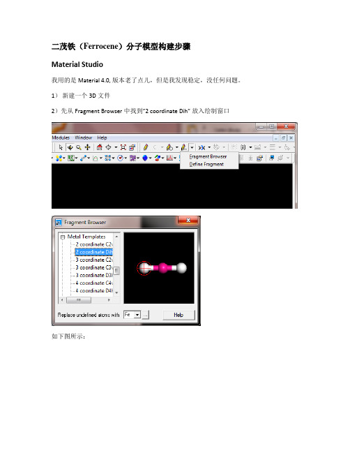
二茂铁(Ferrocene)分子模型构建步骤Material Studio我用的是Material 4.0, 版本老了点儿,但是我发现稳定,没任何问题。
1)新建一个3D文件2)先从Fragment Browser中找到”2 coordinate Dih”放入绘制窗口如下图所示:3)再从”Fragment Browser”中选择Ligand下面的Cyclopentadienyl,添加连接到Fe的两端完成后如果所示:4)下面的一步非常关键,选择“Measure/change”下的“Torsion”然后连接H、第一个五元环的中心、Fe和另外一个环上的H,如下图所示。
5)选择左侧“Property”下Filter的Torsion,然后双击,改角度为36度。
不要跨过Fe而选择两边的两个H和两个中心原子,不然不能修改角度(我也不知道为什么,但是我摸索了很久才发现这个)6)然后再Build下选择Symmetry,Find Symmetry,结果如下:Gaussian View 1)选择五元环:删除C上的两个H然后再添加一个H,结果如图:显示坐标:3)选择Edit菜单中的Point Group,选择Very loose(0.3),然后选择左边的D5h,点击Symmetrize得到结果如下:4)然后在坐标原点(也就是五元环的中心)加入X原子5)现在用Edit->PBC加入第二个五元环:修改C为3.3,修改Cell Replication的c为2添加完第二个五元环后,取消勾选Show Reference Cell Edges和Show Replicate Cell Edges。
6)用二面角编辑工具,选择C2,X11,X22和C13然后修改二面角为36度。
7)再次应用Point Group Symmetry,点击Symmetrize,把坐标原点移到两个五元环中间,在原点处加入Fe原子删除两个X原子和与他们相连的冗余键。
三叶崖爬藤DNA提取及RAPD引物筛选
所用三 叶崖爬藤采 自浙江省东 阳市 山区 , 供试 部分 为新
收稿 日期 :0 2一O 21 1—1 1
涤 ,00 0rm n离心 3m n 弃去上清液 , 1 0 i / i, 加入 0 5mL双蒸水 .
[] J .广西植物 ,0 82 ( )4 7— 5 . 2 0 ,8 4 :4 4 0 [] 4 奥斯伯 FM, 金斯顿 R E .精编分子生 物学实验指南 [ .4版. il
北 京 : 学 出版 社 ,0 5:7— 8 科 20 3 3 .
作者简介 : 郭
勇( 94 )男 , 18 一 , 湖北公 安人 , 研究 实习员 , 主要从 事
引 物 ( 京 金 斯 瑞 生 物 科 技 有 限 公 司 生 产 ) 南 。
1 3 试 验 方 法 .
药 …。三叶崖爬 藤生 于 阴湿 山坡 、 山沟 或溪 谷旁林 下 , 主要
分 布 于 我 国西 南 及 长 江 以南 各 地 。三 叶 崖 爬 藤 以块 根 或 全 草
入药, 具有清热解毒 、 祛风化痰 、 活血止痛的功能 , 药理试验表 明三叶崖爬藤提取物有抗病 毒作用 、 明显 的消炎镇痛 及
1 材 料 与 方 法 1 1 试 验 材料 。
( 20 0rmn 1 i) 1 0 / i,0m n 。转 移离心后 的上清 液至新管 中 ( 必 要时用 c 重提 1 ) 加入 等体积 冰冷 的异丙 醇 , 合均匀 。 I 次 , 混 室温 下离 心( 20 0rm n 1 i) 弃去 上清液 , 1 0 i ,0m n , / 倒置离 心管
江苏农业科 学
Ender-3 Pro Series 3D Printer 使用说明书

To be the Chief Evangelist Array【To make Top-quality 3D printer】◆This guide is for the Ender-3 Pro Series of 3D printers.◆Select the correct input voltage to match your local mains(230V or 115V)◆Because of software/hardware upgrades and modeldifferences, new revisions may not be listed in this guide.◆Please plug the power cord into a three-hole power jack.◆Detailed instructions for use are available on the SD card.Notes1.Do not use the Printer in any way other than described herein to avoid personal injury or propertydamage.2.Do not place the Printer near flammables, explosives or heat sources. It is best to place it in a well-ventilated, low-dust environment.3.Do not expose the Printer to violent vibration or any unstable environment. This will cause poor printquality.4.The filaments recommended by the manufacturer are preferred as to avoid clogging in the hot endand/or Printer damage.5.Do not use any other power cable than the one supplied. Use a grounded three-prong power outlet.6.Do not touch the nozzle or hot bed during printing. Keep hands away from machine while in use toavoid burns or personal injury.7.Do not wear gloves or loose clothing when operating the Printer. These loose articles can becomecaught in moving parts and cause personal injury or Printer damage.8.Clean off filament from the nozzle tip with the provided pliers before the nozzle cools. Do not touch thenozzle directly. This can cause personal injury.9.Clean the Printer frequently. With the machine powered off, clean the printer body with a dry cloth toremove dust, adhered printing materials and foreign objects on guide rails. Use glass cleaner orisopropyl Alcohol to clean the print surface before every print for consistent results.10.Children under 10 years of age should not use the Printer without supervision.Preface1.Introduction ...………………………............12.Screen Information........……………….........23.Loading Filament......................................34.Bed Leveling (4)ContentsDear consumers,Thank you for choosing our products. For the best experience, please read the instructions before operating the Printer. Our 3D team is always ready to provide you with assistance. Please contact us via the phone number or e-mail address provided at the end when you encounter any problem with the Printer.For a better experience in using our product, you may learn how to use the Printer in the following ways: 1. View the accompanied instructions and videos on the SD card.2. Visit our official website at You will find relevant software/hardware information, contact details and operation and maintenance instructions on the website.5.Software Installation ..………………96.Preparing to Print……………………107.Trouble-shooting ……………………118.Circuit Wiring Diagram (12)1.SD Slot and USB Port2.Control Box3.Print Surface4.Control Knob5.Display Screen6.Nozzle Assembly7.Spool Holder8.Extruder (E) Stepper9.Power10.Y Limit Switch11.Y Stepper12.Coupling13.Z Stepper14.Z Limit Switch15.X Limit Switch16.X Stepper6521431615 7814913101112Information DisplayedSet Temperature of the NozzleCurrent Temperature of the NozzleSet Temperature of the Hot BedCurrentTemperature ofthe Hot BedPart Cooling Fan Speed Current Location of the nozzlePrint Time Print Progress Prompt MessagePrint Speed ModelPush :OK/Enter Sub Menu Turn :Change Option/Value3. 1. PreheatMethod 1Method 22. FeedingPress and hold the extruder lever then insert 1.75mm filament through the small hole of the extruder. Continuefeeding until you see filament come out the nozzle.Tip :How to Replace the Filament ?1、Cutting filament near the Extruder and slowly feed new filament until they are fed into the new filament.2、Preheating the nozzle and withdraw the filament quickly and feed the new filament.1. Prepare →Auto Home. Wait for the nozzle to move to theleft/front of the platform.2. Prepare→Disable Steppers(Close stepper drive,releasemotor)3. Move the nozzle the front/left leveling screw and adjust the platform height by turning the knob underneath. Use a piece of A4 paper (standard printer paper) to assist with the adjustment, making sure that the nozzle lightly scratches the paper.4. Complete the adjustment of the screw on all 4 corners.5. Repeat above steps 1-2 times if necessary.12341. Double click the Cura icon to install the Cura Slicing Software.2. Start Cura from the Start Menu.3. Select Other→Creality CR-10→Printer Name :Ender-3 Pro→Add Printer.4、Setting→Printer→Manage Printers...5、Change Printer Settings to (220,220,250).Ender-3 Pro6.1.SlicingInsert SD card into computer with Reader.1. Open file2. Select file3. Open4. Save to SD Card 2.PrintingInsert the SD cardSelect “Printfrom SD”Select the fileto be printed8Shenzhen Creality3D Technology CO.,LTD.After-Sales Service Tel: +86 400 6133 882 +86 755 8523 4565 O f f i c i a l W e b s i t e : Company Address:12th Floor, Building No.3, Jinchengyuan Industrial Area, Tongsheng Community, Dalang Street, Longhua District, ShenzhenV1.0。
引用:第三代测序技术简介-山仑魔的日志-网易博客
引用:第三代测序技术简介-山仑魔的日志-网易博客引用:第三代测序技术简介默认分类2010-05-04 15:55:45 阅读255 评论0 字号:大中小订阅第三代测序技术简介如果有人告诉你用显微镜实时观测单分子DNA聚合酶复制DNA,并用它来测序,你一定会认为他异想天开,没有一点生物的sense。
我最初就是这样认为的,然而它不仅可以实现,而且已经实现了!这个就是被称为第三代的测序技术,Pacific Biosciences公司推出的“Single Molecule Real Time (SMRT?) DNA Sequencing”(单分子实时DNA测序)。
我有幸在NIH听到了这个技术发明人Stephen Turner博士的讲座,根据自己粗浅的理解记录整理一下。
要实现单分子实时测序,有三个关键的技术。
第一个是荧光标记的脱氧核苷酸。
显微镜现在再厉害,也不可能真的实时看到“单分子”。
但是它可以实时记录荧光的强度变化。
当荧光标记的脱氧核苷酸被掺入DNA链的时候,它的荧光就同时能在DNA链上探测到。
当它与DNA链形成化学键的时候,它的荧光基团就被DNA聚合酶切除,荧光消失。
这种荧光标记的脱氧核苷酸不会影响DNA聚合酶的活性,并且在荧光被切除之后,合成的DNA链和天然的DNA链完全一样。
第二个是纳米微孔。
因为在显微镜实时记录DNA链上的荧光的时候,DNA链周围的众多的荧光标记的脱氧核苷酸形成了非常强大的荧光背景。
这种强大的荧光背景使单分子的荧光探测成为不可能。
Pacific Biosciences公司发明了一种直径只有几十纳米的纳米孔[zero-mode waveguides (ZMWs)],单分子的DNA聚合酶被固定在这个孔内。
在这么小的孔内,DNA链周围的荧光标记的脱氧核苷酸有限,而且由于A,T,C,G这四种荧光标记的脱氧核苷酸非常快速地从外面进入到孔内又出去,它们形成了非常稳定的背景荧光信号。
而当某一种荧光标记的脱氧核苷酸被掺入到DNA链时,这种特定颜色的荧光会持续一小段时间,直到新的化学键形成,荧光基团被DNA聚合酶切除为止(见图)。
Focusrite版本3用户指南说明书

User GuideTABLE OF CONTENTSOVERVIEW . . . . . . . . . . . . . . . . . . . . . . . . . . . . . . . . . . . . . . . . . . . . . . . . . . . . . . . . . . . . . . . . . . . . .3 Introduction (3)Features . . . . . . . . . . . . . . . . . . . . . . . . . . . . . . . . . . . . . . . . . . . . . . . . . . . . . . . . . . . . . . . . . . . .4 Box Contents (5)System Requirements (5)GETTING STARTED . . . . . . . . . . . . . . . . . . . . . . . . . . . . . . . . . . . . . . . . . . . . . . . . . . . . . . . . . . . . .6 Software Installation (6)Registering your Clarett+ 2Pre (6)Hardware Features (8)Front Panel (8)Rear Panel (9)Connecting your Clarett+ 2Pre (10)Computer audio setup (10)Audio Setup in your DAW (10)Connecting Clarett+ 2Pre to loudspeakers (11)EXAMPLES OF USAGE . . . . . . . . . . . . . . . . . . . . . . . . . . . . . . . . . . . . . . . . . . . . . . . . . . . . . . . . . .131. Recording a solo artist (13)2. Using the optical connections (15)3. Using the Clarett+ 2Pre as an on-stage mic pre-amp (16)FOCUSRITE CONTROL - OVERVIEW . . . . . . . . . . . . . . . . . . . . . . . . . . . . . . . . . . . . . . . . . . . . . . .17 CLARETT+ 2PRE TECHNICAL SPECIFICATIONS . . . . . . . . . . . . . . . . . . . . . . . . . . . . . . . . . . . . .18 Performance Specifications (18)Physical and Electrical Characteristics (19)TROUBLESHOOTING . . . . . . . . . . . . . . . . . . . . . . . . . . . . . . . . . . . . . . . . . . . . . . . . . . . . . . . . . . .20 COPYRIGHT AND LEGAL NOTICES . . . . . . . . . . . . . . . . . . . . . . . . . . . . . . . . . . . . . . . . . . . . . . . .20OVERVIEWWARNING: Excessive sound pressure levels from earphones and headphones can causehearing loss.WARNING: This equipment must only be connected to USB Type 2.0+ or Thunderbolt 3.0+ ports. IntroductionThank you for purchasing this Clarett+ 2Pre, an audibly stunning, pure-sounding, bus-powered interface for PC or Mac to take you on your creative journey. Independent A-D and D-A converters bring you closer than ever to your music and improved D-A dynamic range enables you to capture every detail.This User Guide provides a detailed explanation of the hardware to help you achieve a thorough understanding of the product’s operational features. We recommend you take the time to read the Guide, so you are fully aware of all the features Clarett+ 2Pre has to offer.IMPORTANT: As well as this User Guide, you will need the Focusrite Control Software Guide which can be downloaded from /downloads.This contains full details of Focusrite Control, the software application designedspecifically for use with the Focusrite Clarett+ range of interfaces.If either User Guide does not have the information you need, please go to , where you can find articles and tutorials beyond the scope of this user guide. A Getting Started video tutorial is also available, at/get-started/ClarettPlus-2Pre.FeaturesClarett+ 2Pre has two next-generation, high-performance Clarett+ preamps with a preamp design that brings masses of headroom, low distortion and low noise. New and improved A-D and D-A converters capture more accurate recordings, and the independent A-D and D-A converters deliver extremely low noise and high dynamic range. Vocals will shine with the All-analogue Air, its circuitry emulating the classic Focusrite ISA 110 preamp. J-FET instrument inputs offer dedicated, ultra-high-impedance, extremely wide audio bandwidth, and mimic guitar amp inputs to preserve the natural tone of guitars.The accompanying software application, Focusrite Control, is designed to let you easily configure the Clarett+ 2Pre with signal routings appropriate for most common recording tasks, and for more complex situations, it provides extensive routing and monitoring options. You can download Focusrite Control from /downloads.iPad and iPhone users can additionally download Focusrite iOS Control from the App Store®. The app communicates via WiFi with Focusrite Control running on your computer, and lets you adjust your monitor mixes and input settings from your iOS device. See the Focusrite Control User Manual for more information.Box ContentsAlong with your Clarett+ 2Pre you should have:• External 12 V DC mains Power Supply Unit (PSU)• USB-C to USB-A cable• USB-C to USB-C cableFocusrite Control is available at /downloads. On Windows, Focusrite Control will also install the driver required. Mac users: Clarett+ 2Pre is class-compliant on Macs, therefore no drivers are required.As a Clarett+ owner, you are also entitled to a selection of third-party software. Go to / included_software/ClarettPlus-2Pre to find out what’s included.System RequirementsIMPORTANT – Please visit the following link for up-to-date information on computer andoperating system compatibility for all Clarett+ products:Click Clarett+ range on the Downloads page. This will take you to a page with all the downloads which are available for the Clarett+ range.To download the Focusrite Control version you need, click the appropriate Download button.Note that the Windows driver is included within the Focusrite Control download. No additional driver is needed for Macs.Registering your Clarett+ 2PreIf you are having trouble with the steps below, please watch our video guide here:/get-started/ClarettPlus-2Pre.1. Go to /register/.2. I f you do not have already have a Focusrite/Novation account, select CREATE AN ACCOUNT and follow the on-screen instructions.3. I f you do have an account, log in and select REGISTER A NEW PRODUCT:4. S elect your Clarett+ device from the Product drop-down list and enter your device’s Serial Number at the bottom of the page. You can find the serial number on the underside of the Clarett+ 2Pre, and also on the gift box. Then click Set Serial Number.5. F ollow the rest of the on-screen instructions to finish registering your device.6. W hen registration is complete, your Product will appear in your Account under the My Hardware tab.7. A ll your bundled software can be found under the My Software tab in your accountHardware FeaturesFront PanelThe front panel includes input gain controls and input connectors for Mic, Line and Instrument signals for both channels, and also monitoring controls.1. INPUTS 1 & 2 – Combo XLR input sockets for each channel - connect microphones via an XLR connector, or instruments (e.g., guitar) or line level signals via ¼” jacks. Either TRS (balanced) or TS (unbalanced) jack plugs can be used for instruments or line level signals.2. 48V – two switches enabling 48 V phantom power at the Combo connectors’ XLR contacts for mic inputs 1 and 2. Each switch has a red LED to show when phantom power is enabled. Note that not all microphones require phantom power . If you are unsure whether your microphone needs it to work, please read the microphone documentation.3. Gain 1 and 2 – two rotary controls: adjust input gain for signals at Inputs 1 and 2 respectively. The gain controls have LED ‘halos’ to confirm signal level: green indicates an input level of at least -42 dBFS (i.e., ‘signal present’), the ring then turns orange when the signal level reaches -6 dBFS, and red at 0 dBFS.4. INST – two red LEDs which illuminate when Instrument mode is selected for the jack Inputs 1 or 2 from Focusrite Control software. When Instrument mode is selected, the line input is converted to a high impedance unbalanced input. You can connect instruments via a 2-pole (TS) jack plug here.5. AIR – two yellow LEDs which illuminate when the AIR function is selected for each input from Focusrite Control . AIR modifies the input stage’s frequency response to model classic, transformer-based Focusrite ISA microphone preamps.6. (USB active) – a green LED which illuminates when the unit has established a connection with the computer to which it is connected.7. (Locked) – a green LED which confirms clock synchronisation, either to the Clarett+ 2Pre’s internal clock or to the external digital input.8. MONITOR – main monitor output level control – this control will normally control the level at the main monitor outputs on the rear panel, but can be configured in Focusrite Control to adjust both pairs of analogue outputs.9.control. The headphone output always carries signals routed to analogue outputs 3 and 4 (as a stereo pair) in Focusrite Control . 10. POWER – green LED confirming DC power is connected.Rear Panel1. LINE OUTPUTS 1 to 4 – four balanced analogue line outputs on ¼” jack sockets; use TRS jacksfor a balanced connection or TS jacks for unbalanced. Line Outputs 1 and 2 will generally be used for driving the main L and R speakers of your monitoring system, while Outputs 3 and4 can be used for connecting additional line level equipment (e.g., outboard FX processors).Signals routed to all the outputs may be defined in Focusrite Control.2. OPTICAL INPUT– a TOSLINK connector carrying eight channels of digital audio in ADATformat at 44.1/48 kHz sample rate or four channels at 88.2/96 kHz. This input is disabled at 176.4/192 kHz sample rates. This input is also capable of accepting a stereo optical S/PDIF source.3. – USB-C™ connector; connect the Clarett+ 2Pre to your computer with either the suppliedUSB-C to USB-C or USB-C to USB-A cable.4. MIDI IN and MIDI OUT – standard 5-pin DIN sockets to connect external MIDI equipment. Youcan send/receive MIDI data between your computer and external MIDI devices.5. External DC power input – power the Clarett+ 2Pre via the separate AC adaptor (PSU) supplied.The PSU is a 12 V DC unit rated at 1.5 A. The Clarett+ 2Pre can also be powered from a computer via USB connection, provided the computer has a 15 W Type-C™ port. See Clarett+ 2Pre USB Bus Power Information to check if your computer has this port: if not, please use the supplied AC adaptor.6. Power On/Off switch.7. Kensington security slot– secure your Clarett+ 2Pre to a suitable structure if desired.Connecting your Clarett+ 2PreThe Clarett+ 2Pre has a USB-C™ port (on the rear panel). Once the software installation is complete, connect the Clarett+ 2Pre to your computer using one of the supplied USB-C cables.The Clarett+ 2Pre can be powered either with the supplied AC adaptor (PSU), or via the USB connection, provided your computer has a 15 W Type-C™ port. See Clarett 2Pre USB Bus Power Information to check whether your computer has a port of this type.Turn the unit on with the power switch.Computer audio setupWhen you connect your Clarett+ 2Pre to your computer for the first time, you will need to select it as the audio input/output device.• macOS: selection is made in System Preferences>Sound: select the Focusrite device on both the Input and Output pages.• Windows: selection is made in Control Panel>Sound: right-click on the Focusrite device and select Set as Default Device in both Recording and Playback tabs.If you have any problems, full details of how to select the Clarett+ 2Pre as the audio device can be found at /get-started/ClarettPlus-2Pre.After the first connection, your OS should automatically select the Clarett+ 2Pre as the default audio device.Audio Setup in your DAWAfter installing the drivers and connecting the hardware, you can start using the Clarett+ 2Pre with your DAW.Please note - your DAW may not automatically select the Clarett+ 2Pre as its default I/O device. In this case, you must manually select the driver on your DAW’s Audio Setup* page, and select Clarett+ 2Pre (Mac) or Focusrite USB ASIO (Windows). Please refer to your DAW’s documentation or Help files if you are unsure where to select the Clarett+ 2Pre as your audio device.* Typical name – page names may vary with DAWConnecting Clarett+ 2Pre to loudspeakersThe 1/4” jack LINE OUTPUTS 1 and 2 on the rear panel will normally be used to drive monitoring speakers. Self-powered monitors have internal amplifiers, and may be connected directly. Passive loudspeakers will require a separate stereo amplifier; in this case, the outputs should be connectedto the amplifier’s inputs.Professional equipment will generally have balanced inputs. If your amplifier or powered speakers have balanced inputs, use 3-pole (TRS) 1/4” jacks to connect them to the Clarett+ 2Pre.All line output connectors are 3-pole (TRS) ¼” jack sockets, and are electronically balanced. Typical consumer (hi-fi) amplifiers and small powered monitors will have unbalanced inputs on RCA sockets.Connecting two pairs of monitorsYou can connect two pairs of monitor speakers using the Clarett+ 2Pre’s four line outputs. You can adjust the level of each pair independently in software (via Focusrite Control), or the level of both pairs together with the hardware monitor knob.Any mix sent to line outputs 3 and 4 (“Additional monitor speakers” in the diagram below) will also be sent to the headphone output. Please note the Clarett+ 2Pre doesn’t include speaker switching; you can purchase third-party hardware for this purpose.IMPORTANT:LINE OUTPUTS 1 and 2 have “anti-thump” circuitry that protects your speakers if theClarett+ 2Pre is turned on while the speakers (and amplifier if used) are connected andactive.LINE OUTPUTS 3 and 4 do not have this circuitry. If you’re using additional speakersconnected to these outputs, power your Clarett+ 2Pre on first, then turn on the speakersor power amplifier.But get into the habit of following this general rule in any case - it is good audio practiceto turn on any speaker system after turning on the equipment feeding it.EXAMPLES OF USAGEThe Clarett+ 2Pre is an excellent choice for many recording and monitoring applications. Some typical configurations are shown below.1 . Recording a solo artistThis setup illustrates a typical configuration for multitrack recording with DAW software on your computer.In this case, two sources – a microphone and a guitar – are connected to the Clarett+ 2Pre’s inputs. As the guitar is connected to Input 2, ensure Instrument mode is selected for Input 2 from Focusrite Control, and the INST LED is illuminated.The connection to the computer running DAW software is via a USB cable. This will carry all input and output signals between the DAW and the Clarett+ 2Pre. Once the audio setup is correctly configured in the DAW, each input source will be available for recording.A mix of the recorded tracks will be available at Line Outputs 1 and 2, so you can hear the results in the speakers.It is possible the performer may prefer to hear a monitor mix of voice and instruments adjusted to their taste. Focusrite Control lets you define a custom monitor mix for the artist and this mix may include the current input signals as well as previously recorded DAW tracks.You can route a musician’s stereo monitor mix to Outputs 3 and 4, and it will then be available at the Clarett+ 2Pre’s headphone socket. If you need to send the monitor mix to more than one musician, you can use the rear panel line outputs to send the mix to a headphone amplifier.When you monitor inputs directly, make sure you mute any DAW channels you record to. If the DAW channels are not muted, the musician will hear two signals: one direct, and one delayed via the DAW. Please refer to the Focusrite Control User Guide (download from /downloads) for more details on setting up monitor mixes.A note about latencyYou will probably have heard the term “latency” used in connection with digital audio systems. In the DAW recording application described above, latency is the time it takes for your input signals to pass through your computer and audio software, and back to you.While not an issue for most recording situations, latency can be a problem for a performer who wishes to record while monitoring their input signals. This might be the case if you need to increase your buffer size, which could be needed when you record overdubs on a large project using many DAW tracks, software instruments and FX plug-ins.Common symptoms of a buffer setting that is too low could be glitching audio (clicks and pops), or a particularly high CPU load within your DAW (most DAWs have CPU readouts). If you experience this on a Mac, you can raise the buffer size from the DAW application itself; on a Windows PC you will need to change this from the ASIO ControlPanel which can usually be accessed from your DAW Setup Preferences*.The Clarett+ 2Pre, in conjunction with Focusrite Control, allows “low latency monitoring”, which overcomes this problem. You can route your input signals directly to the Clarett+ 2Pre’s headphone and line outputs. This enables the musicians to hear themselves with ultra-low latency – i.e., effectively in “real time” – along with computer playback. The input signals to the computer are not affected in any way by this setting. However, note that any effects being added to the live instruments by software plug-ins will not be heard in the headphones in this case, although the FX will still be present on the recording.* Typical name – page names may vary with DAW2 . Using the optical connectionsIn addition to two analogue inputs, the Clarett+ 2Pre has an ADAT input port (OPTICAL IN ) whichcan provide eight additional audio inputs at 44.1/48 kHz sample rate or four at 88.2/96 kHz. Using a separate 8-channel microphone preamplifier equipped with an ADAT output – such as the Clarett+ OctoPre – provides a simple method of expanding the Clarett+ 2Pre’s input capability.U p t o 10 M i c /L i n e S o u r c e sThe Clarett+ v’s OPTICAL OUT port is connected to the Clarett+ 2Pre’s OPTICAL IN port with a single TOSLINK optical cable. The two devices must be synchronised to ensure audio passes cleanly, without clicks and pops. To do this in Focusrite Control go to Device Settings and set the Clock Source to ADAT . Both devices must be set to the same sample rate.You can route the additional ADAT inputs in the same way as other inputs in Focusrite Control . The ADAT inputs can form part of any musician’s headphone mix, as needed.3 . Using the Clarett+ 2Pre as an on-stage mic pre-ampThe Clarett+ 2Pre automatically stores Focusrite Control settings within the hardware. This feature lets you configure it as a pair of inputs – mic, line or instrument – for use as a stand-alone device. This allows you to use it on stage in a live environment where no computer connection is needed, for example.In the example illustrated, a mic and a guitar are connected to the Clarett+ 2Pre’s inputs; Outputs 1 and 2 go to the main PA system. The performer can adjust the mic and guitar volume separately from the front panel.FOCUSRITE CONTROL - OVERVIEWFocusrite Control is the software application used with the Clarett+ 2Pre, which can be downloaded from /downloads. An iOS app allowing WiFi control of Focusrite Control is available, from the Apple App Store.Focusrite Control allows you to create a custom monitor mix for each musician, and specify the routing of all audio signals to the physical audio outputs. Sample rate and clock source selection are also available from Focusrite Control.Focusrite Control has its own, dedicated User Guide, which has detailed operatinginstructions for all aspects of the software. This may be downloaded from/downloads.CLARETT+ 2PRE TECHNICAL SPECIFICATIONS Performance SpecificationsWhere possible, specifications are measured to AES17. Unless stated, all specification measurements are unweighted.Physical and Electrical CharacteristicsTROUBLESHOOTINGFor help getting started with your Clarett+, please visit:/get-startedIf you have any questions or need any help at any time with your Clarett+, please visit our Help Centre.Here you can also contact our support team:COPYRIGHT AND LEGAL NOTICESFocusrite, Clarett and OctoPre are registered trade marks of Focusrite Audio Engineering Ltd. in the United States and other countries.ADAT is a registered trademark of inMusic Brands in the US and other countries.iOS, iPhone, iPad and App Store are trademarks of Apple Inc., registered in the US and other countries and regions.USB Type-C® and USB-C® are registered trademarks of USB Implementers Forum.Thunderbolt is a trademark of Intel Corporation or its subsidiaries in the US and/or other countries.2021 © Focusrite Audio Engineering Limited. All rights reserved.。
- 1、下载文档前请自行甄别文档内容的完整性,平台不提供额外的编辑、内容补充、找答案等附加服务。
- 2、"仅部分预览"的文档,不可在线预览部分如存在完整性等问题,可反馈申请退款(可完整预览的文档不适用该条件!)。
- 3、如文档侵犯您的权益,请联系客服反馈,我们会尽快为您处理(人工客服工作时间:9:00-18:30)。
Vector Modulator
Amplifier VSWR & Power Control Vector Modulator Isolator
Isolator
EPCglobal UHF Architecture
Antenna
IQ Modulator Power Divider Mixer
Fundamentals
M/A-COM Isolator and Circulator Products October 2007
North America 800.366.2266 • Europe +44 (0) 1908.574200 • Asia/Pacific +81.44.844.8296 •
This product selection guide contains a broad range of our standard product offerings. For the full line of circulator and isolator products visit our Web site at
Circulator and Isolator Products
M/A-COM
/passives
Circulator and Isolator Products
M/A-COM
/passives
High Performance Circulators
We work with you
Tyco Electronics is a leading global provider of engineered electronic components, network solutions and wireless systems with 2006 sales of $13 billion to customers in 150 countries. We design, manufacture and market products for customers in industries from automotive, appliances, and aerospace and defense to telecommunications, computers and consumer electronics. With over 8,000 engineers and worldwide manufacturing, sales and customer service capabilities, Tyco Electronics’ commitment is our customers’ advantage. The M/A-COM business is in the Wireless Systems segment of Tyco Electronics and is a leading innovator of wireless technology for critical communications, radar and defense applications. We are happy to work with you on customized products or standard product variations. Please contact us at or 800-366-2266.
M/A-COM, TE logo, and Tyco Electronics are trademarks. ©2007 M/A-COM, Inc. 5-1773448-6/ Oct07 / xM
M/A-COM Circulator and Isolator Products
Typical System Block Diagrams
Circulator Driver Amp
Baseband & DSP Processing
Low third order, and sometimes fifth order IMD products, are a critical parameter when choosing a circulator or isolator. Two CW tones (f1 and f2) are combined and fed into the Device Under Test (DUT). The resulting output is measured on a spectrum analyzer. The third order, and occasionally the fifth order, products are the critical unwanted frequency IMD products that are measured. For additional information, reference Application Note ANI-001 on our Web site:
0.75 x 0.75 0.75 x 0.75 0.75 x 0.75 0.75 x 0.75
200 200 200 200
200 200 200 200
0.25 0.25 0.25 0.25
Detector Diode
Attenuator Variable Delay Line
Amplifier
Splitter
Amplifier
Gain Control Amplifier Coupler
Gain Control Amplifier
+
Combiner Variable Delay Line
200 200 200 200
200 200 200 200
0.25 0.25 0.25 0.25
20 20 20 20
-60 -60 -60 -60
— — — —
Isolators
Frequency (MHz)
2.3 - 2.5
MAFR-000230-000001 MAFR-000226-000001 MAFR-000231-000001 MAFRIN0520 (outline drawing 9)
M/A-COM
/passives
Typical Cellular/WiMAX BTS Architecture
Sector Antenna Coupler
Diplexer
Fixed Delay Coupler
Isolator
M/A-COM circulators and isolators have been used extensively in the RF and telecommunications industries for more than 30 years. Our industry leading products can be found in systems ranging from wireless infrastructure power amplifiers for the cellular market to higher frequency WiMAX signal distribution equipment. Our innovative line of circulators and isolators has excellent RF performance in frequency ranges from 869 MHz to 3.6 GHz. • M/A-COM high performance isolators and circulators assure clean transmit signals by offering low insertion loss and superior IMD performance down to -75 dBc. • Ferrite performance in transmit applications is critical because the ferrite is located in the high power path after the power amplifier and is the last component before the filter/diplexer. Any degradation to the transmit signal is not correctable before transmission at the antenna. The ferrite must handle the high power transmit signal without breakdown or degradation over time. • Insertion loss of the ferrite is a critical parameter and needs to be as low as possible to minimize the power loss after the high power amplifier. At 40 Watt tone power transmission, each 0.1 dB of insertion loss results in 250 mW of lost transmit power
Loss (dB)
Isolation (dB)
IMD (dBc)
Tab Hgt (mm/in)
869 - 894 925 - 960 1805 - 1880 1930 - 1990
MAFRIN0536 MAFRIN0512 MAFRIN0532 MAFRIN0540 (outline drawing 6)
Pout (dB)
3rd order products
