MODIFIED ULTRAVIOLET-CURABLE WATER DISPERSIBLE POLYURETHANE-ACRYLATES
ULTRAVIOLET-CURABLE COATING

专利名称:ULTRAVIOLET-CURABLE COATING 发明人:KIRIYAMA YOSHIYUKI,MORIGAKAZUSUKE,MATSUDAMITSUHIRO,SHINOHARA TOSHIO 申请号:JP8419689申请日:19890403公开号:JPH02263873A公开日:19901026专利内容由知识产权出版社提供摘要:PURPOSE:To provide the title coating adequately curable in a short time even if electrically conductive filler is contained, containing, as photochemical reaction initiator, a titanocene compound. CONSTITUTION:The objective coating incorporated with electrically conductive filler, containing, as photochemical reaction initiator, a titanocene compound of e.g. the formula (R<1> is cyclopentadienyl-, indenyl-, etc.; R<2> is six-membered carbon ring where one or both of the ortho sites against metal carbon bond is substituted with F, five to six-membered heterocycle, etc.) [e.g. bis(cyclopentadienyl)-bis(4-decyloxy-2,3,5,6tetrafluorophenyl)-titanium]. It is preferable that the difference in refractive index between the resultant coating film and a clear coating film free from said electrically conductive filler is <0.3 and the present coating contains transparent spherical glass beads <=100mu in the medium diameter.申请人:DAINIPPON TORYO CO LTD更多信息请下载全文后查看。
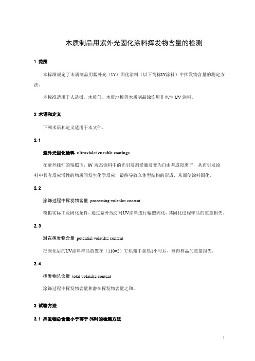
木质制品用紫外光固化涂料挥发物含量的检测

木质制品用紫外光固化涂料挥发物含量的检测1 范围本标准规定了木质制品用紫外光(UV)固化涂料(以下简称UV涂料)中挥发物含量的测定方法。
本标准适用于人造板、木质门、木质地板等木质制品涂饰用非水性UV涂料。
2 术语和定义下列术语和定义适用于本文件。
2.1紫外光固化涂料ultraviolet curable coatings在紫外线灯的辐照下,UV液态涂料中的光引发剂受激发变为自由基或阳离子,从而引发涂料中具有反应活性的物质间发生化学反应,最终导致立体型结构的形成,从而使涂料固化。
2.2涂饰过程中挥发物含量processing volatiles content模拟实际工业固化条件,通过紫外线灯对UV涂料进行辐照固化,其固化过程样品的重量损失。
2.3潜在挥发物含量potential volatiles content把固化后的UV涂料样品放置在(110±2)℃烘箱中加热1小时后,测得样品的重量损失。
2.4挥发物总含量total volatiles content涂饰过程中挥发物含量和潜在挥发物含量之和。
3 试验方法3.1 挥发物总含量小于等于3%时的检测方法3.1.1 原理称取定量UV涂料样品,模拟工业加工方法将其涂覆到铝制基体上,然后称量铝制基体重量,用紫外光灯对测试样品进行辐照固化,称重测量UV涂料涂饰过程中挥发物含量;把固化冷却后的样品置于(110±2)℃烘箱中加热60min,通过重量损失计算潜在挥发物含量,两者之和为UV涂料的挥发物总含量。
3.1.2 仪器和设备a)铝板(305mm×102mm)或不带胶铝箔(厚度不小于0.05mm)。
注:为方便操作和称重,在铝板上裁切规格相等的三块铝板作为测试样板(测试样板的尺寸必须能保证最小为0.2g的UV涂料涂覆后,达到供货商提供的涂膜厚度要求),使用前,先将裁切好的测试样板放入(110±2)℃的干燥器内,干燥30min。
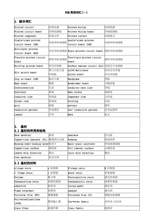
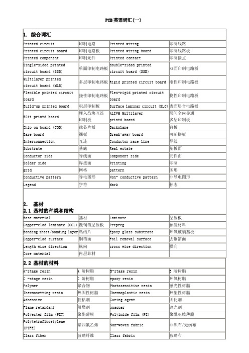
线路板PCB专业英语词汇(制造、测试、缺陷名等)

Mask
掩膜
Solder resist、solder mask
阻焊剂
Solder mask ink
阻焊印料
Dry film solder mask
阻焊干膜
Liquid photosensitive
solder resist
液体光致阻焊剂
Marking ink、legend ink
标记印料
brushing / scrubbing
磨刷
abrasive
磨料
scrubber
磨刷机
mechanical cleaning
机械清洗
chemical clearing
化学清洗
pumice power
浮石粉/火山灰
sand blasting
喷砂
deburring
去披峰/去毛刺
mechanical polishing
Flexible printed circuit board
挠性印制电路板
Flex-rigid printed circuit board
挠性印制电路板
Build-up printed board
积层印制板
Surface laminar circuit (SLC)
表面层合电路板
B2it printd board
Computer-aided manufacturing (CAM)
计算机辅助制造
Routing
布线
Layout
布图设计
Component density
元件密度
Arry
阵列
3.2 形状与尺寸
Conductor
导线
线路板PCB专业英语词汇(制造、测试、缺陷名等)

铜箔面
Foil removal surface
去铜箔面
Length wise direction
纵向
cross wise direction
横向
Core material
内层芯材
2.2基材的材料
A-stage resin
A阶树脂
B-stage resin
B阶树脂
Job traveller
工作流程单
4.2照相底版制作
Artwork
照相底图
Phototool
照相底版
Artwork master
照相原版
Working master
工作原版
Production master
生产底版
Photographic film
照相底片
Silver film
银盐底片
Diazo film
Flexible printed circuit board
挠性印制电路板
Flex-rigid printed circuit board
挠性印制电路板
Build-up printed board
积层印制板
Surface laminar circuit (SLC)
表面层合电路板
B2it printd board
circuit board (SSB)
单面印制电路板
double-sided printed
circuit board (SSB)
双面印制电路板
Multilayer printed
circuit board (MLB)
多层印制电路板
Rigid printed circuit board
PCB-专用术语

85 吸嘴 86 定心爪 87 贴装精度 88 焊接 89 再流焊 90 波峰焊 91 气相焊接 92 组装密度 93 混装技术 94 引线 95 平移偏差 96 旋转偏差 97 贴装速度
98 低中高速贴装机 99 焊端 100 球栅阵列 101 贴装 102 贴装机 103 供料器 104 活化剂
七 、 机械加工成形术语
208 数控 209 电脑数控 210 垫板 211 盖板 212 钻套 213 钻柄 214 切削量 215 犁沟 216 树脂钻污 217 铜箔毛刺 218 玻璃纤维突出 219 碎屑 220 破出 221 磨钻头机 222 激光穿孔 223 牛皮纸 224 粘结层 225 滑移 226 缺胶
brushing,scrubbing scrubber mechanical cleaning
181 超声波清洗 182 喷射清洗 183 化学除油 184 溢流 185 去离子水(DI)
1六86 污化 、 检测术语
195 粘合强度 196 拉脱强度 197 剥离强度 198 弯曲强度 199 伸长率 200 抗扭强度
47 晕圈
haloing
48 粉红圈
pink ring
49 起泡
blister
50 夹杂物
incusion
51 槽边有毛刺
excessive burrs around cavity
52 白斑
measling
53 粉点
mealing
54 漏啤
missing punching
55 锣板不良
poor rounting
187 磨刷 188 磨刷机 189 机械清洗
alkali etchant under cut catalyzing rectifier plating rack anode
微米尺寸三坐标测量机探头的半自动组装及未来工艺链优化说明书

Semi-automated Assembly of a MEMS-Based Micro-scale CMM Probe and Future Optimization of the ProcessChain with a View to Desktop Factory AutomationJames D. Claverley1, Arne Burisch2, Richard K. Leach1, and Annika Raatz21 Engineering Measurement Division, National Physical LaboratoryHampton Road, Teddington, UK, TW11 0LW**********************.uk2 Institute of Machine Tools and Production Technology (IWF),Technische Universität Braunschweig, Braunschweig, DE******************Abstract. The assembly process of a novel micro-scale co-ordinate measuringmachine probe is presented. The process makes use of a semi-automatedminiature robot. The initial tests that led to the full process chain are described,and the full process chain presented. The presented process chain successfullyproduced four assembled probes. Future work is suggested to augment thepresented process chain leading to further automation.Keywords: micro-CMM probe, MEMS, micro-assembly, desktop factory.1IntroductionModern precision engineering demands measurement capabilities of at least equal, if not superior, accuracy to the machining capabilities. This statement is especially true for small components with functional micro-scale features. The required measurement capability is partially realized by the new generation of micro-co-ordinate measuring machines (micro-CMMs), such as the Zeiss F25, however, existing high accuracy probing systems for such machines often lack all the functionality required to complete such measurements [1].The National Physical Laboratory (NPL) has developed a novel micro-scale CMM probe that aims to bring overall measurement uncertainty of micro-CMMs to below 100 nm, while also allowing true isotropic 3D scanning and non-contact surface detection. The probe consists of a triskelion (three-legged) nickel flexure device and a spherical stylus tip.The triskelion device is a MEMS (micro-electrical mechanical system) produced using typical integrated circuit production techniques such as metal deposition and chemical etching [2]. A 7 µm thick piezo-electric (lead zirconium titanate) film is deposited onto the nickel flexures using a sol-gel spinning technique. Each flexure is 2 mm long, 0.2 mm wide and nominally 20 µm thick. The flexures are fabricated on a silicon chip, 14 mm by 14 mm by 1 mm.10 J.D. Claverley et al.The spherical tipped stylus is 2 mm long, 200 µm in diameter with a 70 µm diameter spherical tip. It is produced using micro-electro-discharge machining. A full description of the production process can be found elsewhere [3], [4].Using the deposited PZT as actuators and sensors, the device is designed to vibrate in a direction normal to any measurement surface it encounters. This vibration is used to counteract the disruptive surface forces encountered during micro-scale dimensional measurement and to enable the probe to operate in a non-contact mode, significantly reducing the probing force imparted on the measurement surface in comparison to existing micro-CMM probes [5]. A schema of the device is shown in figure 1.PZT actuators ArrayPZT sensorsMicro-stylusFig. 1. A schema of the vibrating micro-CMM probeThe assembly of the flexure chip and the sphere-tipped stylus, to produce the vibrating micro-CMM probe, presents a number of challenges. These include, but are not limited to, the delicate nature of the 20 µm nickel thick flexures, the difficulty in handling millimetre-sized parts, the surface interaction forces being dominant over gravity during the operation and obscured view of critical process steps due to limited available camera positions. The ideal physical requirements of the assembly of the stylus onto the chip are a positional accuracy of ± 0.5 µm and an angle between the stylus and flexure of 90º ± 0.29º [6].2Assembly Preparation and TestsThere are many demands put on processes for micro-scale assembly. These demands include the need for high precision and repeatability, flexibility and energy efficiency, low cost and suitable workspace volume and shape. Most conventional assembly machines do not guarentee all of these requirements to the level demanded by this product along with a high degree of automation [7]. New approaches for scalable and highly flexible production technology are miniaturized handling devices in the range of several centimetres to a few decimetres [8].2.1Assembly SetupTo complete the assembly of the flexure and the spherical stylus tip, a miniaturized assembly setup using a robot (Parvus) was developed at the Institute of MachineMEMS-Based Micro-scale CMM Probe Chain 11 Tools and Production Technology (IWF) of TU Braunschweig. A micro-gripper [9] was connected to the robot and two microscope cameras were arranged within the workspace with front and lateral views. A fixture was designed and manufactured to hold the triskelion chip on a tip-tilt table within the robot’s workspace. An ultraviolet (UV) light source was also arranged within the workspace. The capability of this setup beyond that of conventional assembly systems, including accuracy, repeatability and the scope for automation, is fully described in [3]. The setup is shown in figure 2.Fig. 2. Setup of the assembly system, robot Parvus and flow box2.2Camera VerificationThe cameras are used during the assembly process to verify the angle between the triskelion and the stylus. Both cameras were verified using a previously calibrated vertical micro-scale artefact. This artefact was positioned directly above the centre of the triskelion device. The camera was thus calibrated to the upper surface of the triskelion device.2.3Experiment with UV Curing AdhesiveUltraviolet curable adhesive was chosen as the most suitable adhesive for the assembly [3]. Several types of UV curable adhesive were investigated specifically focusing on their uncured viscosities. These are shown in table 1.Table 1. Physical properties of several adhesives tested for their suitability [10, 11, 12, 13] Adhesive Viscosity /mPa Hardening at wavelength /nm DELO Katiobond AD 610 400320 –380DELO Katiobond 4578 12400400 –550Vitralit 1605500400 –500Loctite 352 20000 36512 J.D. Claverley et al.Adhesive types DELO Kationbond 4578 and Vitralit 1605 cure under normal white light after a few minutes and are thus not suitable for the assembly process, which may take some minutes. For the adhesive with the lowest viscosity (DELO Katiobond AD610), dipping and application with a hollow dispenser needle (diameter 0.24 mm) deposited an adhesive drop onto a test surface with a diameter of 320 jt m. A similar test using the high viscosity adhesive (Loctite 352) resulted in drops with diameters in the range of 210 jt m to 240 jt m. The aim of the investigation was to select the adhesive that deposited the smallest uncured drop, therefore Loctite 352 was chosen for the assembly process.A Hartmann UV-P 280/2 light source was used to cure the adhesive. After a curing time of 60 s the Loctite 352 adhesive drop was tack free.2.4 Application of Adhesive to TriskelionTo complete adhesive tests on an actual triskelion, a dispenser needle (diameter 0.24 mm) was dipped into an adhesive reservoir. A drop was applied on the central area ofthe triskelion as shown in figure 3.b)adhesive drop500µmFig. 3. A small adhesive drop being deposited (a) in the centre of the triskelion. The resulting adhesive drop is shown at (b).Dipping the dispenser needle into the adhesive reservoir worked well in the first experiments on a test surface (see section 2.3). However, this method does not apply an exact or repeatable amount of adhesive. To solve this problem, the Parvus robot was equipped with a dispenser needle that can directly apply a pre-defined volume of adhesive on to the surface of the triskelion. Additionally, to ensure sufficient contact between the triskelion surface, the stylus and the adhesive, the stylus was also dipped into the adhesive reservoir, as shown in figure 4.a)b)Fig. 4. Gripping the stylus (a) and dipping the end in an adhesive reservoir (b)MEMS-Based Micro-scale CMM Probe Chain 13 2.5Test Assembly of StylusOnce the assembly setup was built, the cameras verified and a gluing strategy devised, it was necessary to complete a trial manual assembly.Firstly, a micro-stylus was selected and prepared by removing it from its transport stub and inspecting it under a 3D microscope. The transport stub is designed to allow easy transport and handling of the stylus without gripping the delicate stylus directly. The design has been suitable to allow transport of the styli from Taiwan to the UK via normal commercial courier. It was possible to grip the stylus on its transport stub with the micro-gripper, however, the necessary force to break the stylus at the neck is too high and experience suggested that the gripper would break. Hence, the stylus was removed manually and placed safely in a gel receptacle, where the gripper could collect it. This process is shown in Figure 5.a)b)Fig. 5. Micro-stylus in transport stub (a), being inspected (b) and collected for assembly (c) Once both adhesive depositing steps were completed, as described in section 2.4, the stylus was positioned over the central area of the triskelion and moved down into contact with it. Finally, the adhesive was cured, fixing the stylus in place as shown in figure 6. To check the stability of the connection between the triskelion and the stylus, a lateral force was applied to the stylus using the micro-gripper, also shown in figure 6b.Fig. 6. The completed test assembly, front view (a), lateral view (b). A stability test is also completed on the stylus (c).3Final Assembly ProcessWorking from all previous experiments and test assemblies, as described in section 2, a full process chain was devised to assemble the micro-probe. This process chain was14 J.D. Claverley et al.developed to allow the maximum amount of preparation before any irreversible steps are conducted. The preparation steps include aligning the fixture within the robot’s workspace and mounting the various adhesive applicators. The irreversible steps include depositing adhesive on the parts, bringing those parts together in assembly and curing the adhesive. These steps should only be completed once all preparation has been performed and it is possible to complete assembly without interruption or breaks.At several stages throughout the assembly process, the Parvus robot was taught the locations of several essential positions within the workspace. This allows the operator to take advantage of as much automation as it was possible to devise in the short time frame of the project. The complete process chain is shown in table 2.Table 2. Complete process chain for assembly of triskelion and stylus, including links to previous figures for reference; the irreversible steps are indicated with an asterisk (*)Process description Reference1 Verify condition of stylus and triskelion under 3D microscope Figure 52 Mount triskelion device and fixture on the tip-tilt table Figure 23 Insert plate for adhesive dipping Figure 4b4 Align tip-tilt table in the workspace of the robot Figure 25 Position the calibrated part for camera calibrationSection 2.26 Arrange cameras (front and lateral) and approx. 30° from horizontal- Align vertical orientation of cameras according to the calibration part7 Teach robot rough position of gripper over the central hole of triskelion8 Teach robot rough position of gripper over the plate for adhesive dipping9 Mount adhesive cartridge with dispenser needle onto robot10 Teach robot rough position of adhesive dispenser over central hole oftriskelion11 Remove adhesive cartridge12 Remove tip-tilt table13 Position gel-tray with stylus within the robot workspace14 Grip the stylus with the micro gripper Figure 5c- If necessary correct stylus’ position within the grippergel-tray15 Remove16 Re-insert tip-tilt table17 Test assembly without adhesive- Test of process 7, re-teach assembly position if necessary18 Mount adhesive cartridge19 Check pressure and dispensing time at adhesive dispenser20 Dispense adhesive drop on plate Figure 4b21* Dispense adhesive drop on the centre of triskelion Figure 322 Remove adhesive cartridge23* Dip stylus in the adhesive drop on the plate Figure 4b24* Assemble the stylus onto the triskelion Figure 6a,b25 Align stylus vertically Figure 6a,b 26* Cure adhesive by ultraviolet light27 Open the gripper and retractMEMS-Based Micro-scale CMM Probe Chain 154Results and ConclusionFour micro-CMM probes were successfully assembled using the method described. The assembly process, as described in table 2, was 30 minutes in duration per probe. The time consuming factor is the lack of adequate feeding systems for micro parts.With automated feeding, the assembly could be completed in 5 minutes. Each completed micro-CMM probe was qualitatively tested to establish the orthogonality of the stylus. Each completed probe was also functionally tested by applying a lateral force on the stylus to verify sound adhesion between the assembled parts.The assembly method uses automation to ensure repeatable volumes of adhesive are deposited on the triskelion and to ensure repeatable placing of the stylus at the triskelion. However, many operations, such as picking up and handling of the stylus, and fine adjustments of the position of the stylus before curing are done under manual control. As a prototype assembly method, processing small volumes of parts, this semi-automation is sufficient. However, should there be a need to scale up the process for higher production volumes, more automation would have to be implemented.5Future WorkWith a view to increasing the automation of the assembly process, several steps can be taken to make robot handling and programming easier.The stylus transport stub should be redesigned so that the micro-gripper can safely remove the stylus without the need for a manual operation and an intermediate receptacle. The styli should also be supplied in cartridges, which will allow for programmable gripping by the micro-gripper. Furthermore, automated feeding of the styli will be necessary to guarantee a continuous assembly process.The triskelion device should be automatically transported to the assembly position. The triskelion device could directly be gripped and positioned by the Parvus with a typical vacuum gripper. Therefore, a tool changer, which is currently under development at the IWF, could be used to switch between the vacuum and the micro-gripper. Alternatively, an additional feeding system for the triskelion devices could bring the parts into the assembly position. Furthermore, an active fixture, as presented elsewhere [8], that clamps and releases the triskelion devices will be necessary.The current camera positions (front and side, elevated at about 30°) are ideal for observing and controlling the adhesive deposition steps and also any stylus manipulation steps. However, they do not allow for quantitative measurement of stylus angle. They are also susceptible to any rotational misalignment on setup and misalignment of reference features on the triskelion. A variable focus camera should be set up directly above the centre of the triskelion to allow for better measurement of the stylus angle and to verify that the sphere tip is directly above the centre of the triskelion. While the process could, theoretically, be run using only this camera, any imperfections in the parts (straightness or flatness errors) will cause errors in the assembly. For adequate control, at least two cameras are required, for ideal control, three cameras should be used.The position of the assembly point, at the centre of the triskelion, should be determined prior to assembly. If the assembly point can be determined with respect to the origin of the Parvus robot, the operator will not need to manually teach the assembly point. Alternatively, a vision system and automated image processing or a laser scanning process could determine the assembly position.16 J.D. Claverley et al.All parts, fixtures and cartridges should be redesigned so that they can fit easilyinside the workspace. This will reduce the need to remove and replace parts during the assembly process.A set of dummy parts should be made to allow these changes to be tested. Using these dummy parts a higher production scale can be simulated without the waste of expensive micro-parts.Acknowledgments. This work was funded by the UK National Measurement Office Engineering and Flow Metrology Programme 2008 to 2011. The authors would like to thank Christopher Jones (NPL), Prof. Dong-Yea Sheu (NTUT) who developed the probe production techniques [4] and the Microsystems and Nanotechnology Centre (Cranfield University) for producing the triskelion devices.The assembly setup installed at IWF used a micro gripper and further knowledge developed within the Collaborative Research Centre 516, funded by the German Research Foundation.References1.Leach, R.K.: Fundamental principles of engineering nanometrology. Elsevier (2009)2.Stoyanov, S., Bailey, C., Leach, R.K., Hughes, B., Wilson, A., O’Neill, W., Dorey, R.A.,Shaw, C., Underhill, D., Almond, H.J.: Modeling and prototyping the conceptual design of 3D CMM micro-probe. In: Proc. 2nd ESITC, Greenwich, September 1-4, pp. 193–198 (2008)3.Claverley, J.D., Sheu, D.-Y., Burisch, A., Leach, R.K., Raatz, A.: Assembly of a novel MEMS-based 3D vibrating micro-scale co-ordinate measuring machine probe using desktop factory automation. In: Proc. IEEE ISAM, Tampere, FI, May 25-27 (2011) ISBN 97816128434144.Sheu, D.-Y.: Micro spherical probe machining by EDM. J. Micromech. Microeng. 15,185–189 (2005)5.Claverley, J.D., Leach, R.K.: A vibrating micro-scale CMM probe for measuring highaspect ratio structures. Microsyst. Technol. 16, 1507–1512 (2010)6.Smale, D., Ratchev, S., Segal, J., Leach, R.K., Claverley, J.D.: Assembly of the stem andtip of an innovative micro-CMM probe. In: Euspen 9th Int. LAMDAMAP, Uxbridge, UK, June 29-July 2, pp. 442–451 (2009)7.Burisch, A., Soetebier, S., Wrege, J., Sattler, R.: Design of a parallel hybrid micro-scararobot for high precision assembly. Mechatronics and Robotics 4, 1374 (2004)8.Burisch, A., Wrege, J., Raatz, A., Hesselbach, J., Degen, R.: PARVUS – Miniaturized robotfor improved flexibility in micro production. J. Assembly Automation 27(1), 65–73 (2007)9.Hoxhold, B., Wrege, J., Bütefisch, S., Burisch, A., Raatz, A., Hesselbach, J., Büttgenbach,S.: Tools for Handling and Assembling of Microparts. In: Büttgenbach, S., Burisch, A., Hesselbach, J. (eds.) Design and Manufacturing of Active Microsystems. Microtechnology and MEMS series, pp. 393–409. Springer, Berlin (2011)10.DELO Industrie Klebstoffe: Product manual (DELO Katiobond AD610) Revision 27, pp.2–5 (2010), http://www.delo.de/fileadmin/datasheet/DELO-KATIOBOND_AD610_(TIDB-GB).pdf (accessed June 29, 2011)11.DELO Industrie Klebstoffe: Product manual (DELO Katiobond 4578) Revision 26, pp. 2–5 (2010) http://www.delo.de/fileadmin/datasheet/DELO-KATIOBOND_4578_(TIDB-GB).pdf (accessed June 29, 2011)12.Etilux: Product manual (Vitralit 1605) Revision: 03/2006, p. 3 (2006),/medias/catalog/multimedia/DocVtralitrev03-06.pdf (accessed June 29, 2011)13.Henkel: Product manual (Loctite 352) Revision: January 2009, pp. 1–2 (2009),/tds5/docs/352-EN.pdf (accessed June 29, 2011)。
