Warman泵的安装
地热循环泵的正确安装方法

地热循环泵的正确安装方法
地热循环泵的正确安装方法如下:
1. 将循环泵装置在回水管道上面,在原本的系统上切除一段管道,将循环泵串接在管路上。
2. 安装水泵之前,应确保管道无渣质,如有杂质,焊渣、污垢等将会对水泵寿命造成损害。
3. 接好电源先试转几分钟,检查启动是否正常,但空转时间不能过长(5秒以内),以防干运转影响陶瓷轴承的寿命。
4. 首次使用时请注意泵的排气,泵腔内有空气的话就起不了增压作用。
用于热水循环连续运转时间达到一周左右,排气一次。
按照上述步骤进行安装,可以有效地确保地热循环泵的正确安装和使用。
如遇到问题建议咨询专业技术人员。
暖气循环泵安装方法
暖气循环泵安装方法
长沙中联泵业为您介绍家用暖气循环泵安装方法
家用暖气循环泵安装方法是对暖气循环泵安装过程最直观地阐述,能够很好地指导暖气循环泵安装,简单易懂,不管是行业人士还是居家的安装新手都能掌握。
下面,小编为大家详细介绍暖气循环泵安装方法。
安装使用方法:
1.安装前应检查循环泵进出水口是否有异物堵塞;
2.装入系统前应将系统管道内的杂物冲洗干净,以免
循环泵运转时杂物缠绕叶轮造成堵转;
3.安装时应用力轻柔,请勿大力,以免损坏泵体;
4.循环泵的进、出口都要设有由任(活接头),以便
装拆。
5.安全接线,连线要采用带地线的三股线的插头, 地
线端与电机外壳联接,以保证安全。
6.本产品噪声低,检查是否转动时,需用螺丝刀顶住
耳朵细听。
以上是中联泵业对暖气循环泵安装方法的详细介绍,中联泵业24年的专业生产经验,齐全的加工检测设备,于同行业中处领先地位,更加充分保证了产品的质量,如今公司产品达二十大系列,一万多种规格。
为客户创造价值,为社会节约资源,2014年中联人将继续秉承着“科技创新、用户至上、追求卓越”的宗旨,为打造"国际品牌"而不懈努力!。
Watson-Marlow 520Di Pump 说明书

操作面板说明:Up :向上Start :启动:换档Stop :停止:确认Down :向下各键功能Start :启动。
泵开始运行。
Stop :停止。
泵运行停止。
Up :向上。
用于菜单选择—使光标上移一个选项。
在储存分装程序时,可通过它来依次显示“9-0”,空格和“Z-A”字符。
Down:向下。
用于菜单选择—使光标下移一个选项。
在储存分装程序时,可通过它来依次显示“A-Z”,空格和“0-9”字符。
Shift :换档。
按下Shift键后,在屏幕的坐下角会显示一个箭头符号,此时数字键盘的功能为对应键的黄色字符所表示的功能。
再按一次Shift键后,箭头符号消失,数字键盘恢复数字输入功能。
Enter :确认。
SHIFT, 0 ( . ):用于输入小数点。
SHIFT, 1 (DIRECTION):在设定分装参数时,设定泵的运行方向。
SHIFT, 4 (MAX):当泵处于手动控制模式或分装开始界面时,使泵以最高速度运行以实现快速预填充或快速排空。
SHIFT, 5 (CLEAR):在数字输入时,清除输入。
SHIFT, 6 (LOAD):用于调入储存在泵中的分装程序。
SHIFT, 7 (MENU):显示主菜单。
SHIFT, 8 (CAL):校准选项。
SHIFT, 9 (INFO):显示系统信息。
1. 开机注意:务必确认电压选择开关符合当前电压后才能开机!初次开机,系统会要求选择菜单语言,520Di目前提供有5种语言的操作界面,分别为英语、法语、德语、西班牙语和意大利语。
一般选择英语,后依次显示Watson-Marlow LOGO、泵基本信息,最后显示系统主菜单。
主菜单有5个选项,分别为:Dose:分装 - 设定、储存、调用分装参数,并执行分装操作。
Calibrate:校准 - 校准流量。
Manual:手动控制 – 手动操作520Di分装泵。
Network:网络控制 – 通过RS232通讯接口来控制520Di分装泵。
【暖通空调知识】热泵系统安装要点

【暖通空调知识】热泵系统安装要点
空气源热泵采暖系统中,水泵是整个水系统循环的动力所在,一般安装在系统的进水口前的管路。
这对安装户式采暖系统极其重要,若要在安装的时候出现错误,将会导致一系列的问题出现。
为了能够减少水泵的问题导致系统不能够正常的工作,安装的时候要注意以下几点:
1.水泵安装的时候要横着放:
针对热泵常用的管道屏蔽泵,水泵安装的时候必须保证电机轴和地平面水平,因此,水泵安装的时候要横着放,如果是竖着安装,不仅会影响水泵的寿命,还会因为水泵温度过高有可能会被烧毁。
水泵里面有一个推力轴承,是石墨的,如果不是水平安装,力会集中在推力轴承里面,时间长了会磨损的越来越薄,叶轮就会和泵体进行摩擦,这样水泵的使用寿命就会因此降低。
另外,水泵的冷却是通过介质来冷却的,如果是竖着安装,介质就会流动不同,所以不能够对电机进行良好的冷却,这样一来,水泵的温度会因为不能及时冷却而过高,时间长了就很容易烧坏电机,今年北京煤改电项目不少就是竖着安装的,用手一摸就能够感受到水泵的温度比较高,这样运行短时间的运行就坏了,必须要对其整改才可以。
2.水泵应安装在系统较低位置的环流处:。
AH & M Pumps Operation Manual-Chinese
•
Tapped Holes (for Eye Bolts) and Lugs (for Shackles) on Warman Parts are for liftingIndividual Parts Only.
泵装配.................................................................................................... …………………………5
框板及盖板螺栓的安装–见图2.......................................…………………………………………………..5
WARMAN INTERNATIONAL LTD
WARMAN PUMPS
ASSEMBLY AND MAINTENANCE
INSTRUCTIONS
SUPPLEMENT ‘P3’
Warman International Ltd. is the owner of the Copyright subsisting in this Manual. The Manual may not be reproduced or copied in whole or in part in any form or by any means without the prior consent in writing of Warman International Ltd.
不允许泵在持续的低流量、零流量或其他可能使介质汽化的条件下运行。其产生的压力会导致人员伤亡和设备受损。
•
DO NOT APPLY HEAT TO IMPELLER BOSS OR NOSEin an effort to loosen the impeller thread prior to impeller removal. Personnel injury and equipment damage couldresult from the impeller shattering or exploding when the heat is applied.
水泵组装操作规程书

水泵组装操作规程书水泵组装操作规程书一、目的为确保水泵组装操作的安全和质量,规范操作流程,提高组装效率和水泵使用性能。
二、适用范围本操作规程适用于各类水泵的组装操作。
三、责任与义务1. 管理部门负责制定和组织实施本规程。
2. 组装工人应严格按照规程执行,确保质量和安全。
四、组装准备工作1. 检查零部件是否齐全和完整,有无损坏。
2. 根据零部件清单准备所需零部件。
3. 检查组装工具的状态和可用性。
五、组装操作步骤1. 将零部件按照组装顺序排列好,并清洁干净。
2. 根据组装图纸,依次将零部件组装在正确的位置上。
3. 使用正确的工具和方法将零部件拧紧,注意不要损坏零部件。
4. 每次组装完成后,要进行检查,确保零部件安装正确。
六、组装注意事项1. 操作人员必须穿戴好劳动防护用具,遵守安全操作规程。
2. 操作过程中严禁随意更改组装顺序或零部件规格。
3. 需要特殊注意的组装环节应有专门指导人员进行指导。
4. 在组装过程中,如遇到异常情况,应立即停止操作,并报告相关人员。
七、质量控制1. 在组装过程中,对关键位置进行质量把关,确保零部件的拧紧力度和安装位置。
2. 组装完成后,进行整体质量检查,确保水泵的质量符合要求。
3. 如发现质量问题,应立即停止组装,并进行问题分析和处理。
八、设备保养与维护1. 在组装过程中,减少零部件的磨损和损坏。
2. 组装完成后,进行设备的清洁与保养工作,延长设备寿命。
3. 定期检查设备的运行情况,及时发现并处理问题。
九、安全防范措施1. 操作人员应接受相关安全培训,并了解操作规程和安全规程。
2. 在操作过程中,特别是在使用工具时,要注意安全操作,避免伤害自己和他人。
3. 严禁在设备运行中进行任何不安全的行为。
十、违规行为及处理1. 对于违反操作规程的行为,将进行相应的纪律处分。
2. 如因违规操作造成设备损坏或人员伤害,将追究违规人员的责任。
以上是关于水泵组装操作规程书的内容,希望能对你有所帮助。
暖气加装循环泵正确方法
暖气加装循环泵正确方法英文回答:Installing a circulation pump for a heating system is a common practice to improve the efficiency and performance of the system. Here, I will explain the correct method to install a circulation pump for a heating system.Firstly, it is important to choose the right type and size of the circulation pump for your heating system. The pump should be able to handle the flow rate and pressure requirements of your system. It is recommended to consult with a professional or an experienced HVAC technician to determine the appropriate pump for your specific heating system.Once you have the right pump, you need to locate the ideal position for installation. The pump should be installed on the return line of the heating system, preferably near the boiler or the heat source. This allowsthe pump to effectively circulate the heated water throughout the system.Next, you need to ensure proper electrical connections for the pump. The pump should be connected to a dedicated electrical circuit with the correct voltage and amperage rating. It is crucial to follow the manufacturer's instructions and local electrical codes when making the electrical connections.After the electrical connections are done, you can proceed to install the pump in the chosen location. Make sure to use appropriate fittings and connectors to secure the pump in place and ensure a leak-free installation. Itis advisable to use isolation valves on both the supply and return lines to allow for easy maintenance and future repairs.Once the pump is installed, it is important to properly bleed the air from the system. This can be done by opening the air release valve on the pump or at other high pointsin the system. Bleeding the air ensures optimal performanceand prevents airlocks in the circulation.Finally, it is recommended to test the system after the pump installation. Check for any leaks, ensure proper water flow, and monitor the system's performance. If everythingis working correctly, you can adjust the pump speed or flow rate as needed to achieve the desired heating comfort.In conclusion, the correct method to install a circulation pump for a heating system involves choosing the right pump, locating the ideal position, making proper electrical connections, securing the pump in place, bleeding the air from the system, and testing the system's performance. Following these steps will ensure an efficient and effective heating system.中文回答:安装循环泵来提升暖气系统的效率和性能是一种常见的做法。
【暖通空调知识】热泵系统安装要点
【暖通空调知识】热泵系统安装要点空气源热泵采暖系统中,水泵是整个水系统循环的动力所在,一般安装在系统的进水口前的管路。
这对安装户式采暖系统极其重要,若要在安装的时候出现错误,将会导致一系列的问题出现。
为了能够减少水泵的问题导致系统不能够正常的工作,安装的时候要注意以下几点:1.水泵安装的时候要横着放:针对热泵常用的管道屏蔽泵,水泵安装的时候必须保证电机轴和地平面水平,因此,水泵安装的时候要横着放,如果是竖着安装,不仅会影响水泵的寿命,还会因为水泵温度过高有可能会被烧毁。
水泵里面有一个推力轴承,是石墨的,如果不是水平安装,力会集中在推力轴承里面,时间长了会磨损的越来越薄,叶轮就会和泵体进行摩擦,这样水泵的使用寿命就会因此降低。
另外,水泵的冷却是通过介质来冷却的,如果是竖着安装,介质就会流动不同,所以不能够对电机进行良好的冷却,这样一来,水泵的温度会因为不能及时冷却而过高,时间长了就很容易烧坏电机,今年北京煤改电项目不少就是竖着安装的,用手一摸就能够感受到水泵的温度比较高,这样运行短时间的运行就坏了,必须要对其整改才可以。
2.水泵应安装在系统较低位置的环流处:另外,为了让水泵更好地工作,安装的时候不要放在系统系统顶部或者是比较高处,而应该安装在系统较低位置的环流处。
如果水泵安装位置比较的高,系统顶部压力相对比较小,当低于工作水温的对应的饱和压力的时候,会引起一部分液体蒸发,蒸发后的汽泡进入压力较高的区域时,受压突然凝结,于是四周液体就向此处补充,造成水力冲击,这种现象也叫汽蚀,汽蚀过程是不稳定的,会使水泵发生振动和产生噪声,同时汽泡还会堵塞叶轮槽道,致使扬程、流量降低,效率下降。
另外,系统较高位置可能会有气体积聚,甚至导致水泵缺水出现干转现象,如果处理不及时,还会烧毁电机。
3.水泵应安装在热泵主机的回水侧:热泵采暖系统中,水泵应该安装在哪个位置?出水侧还是回水侧?如果安装有误,会导致怎样的后果?如果安装在出水侧有可能会使主机换热器抽真空造成流量降低,我们知道水泵的入口压力式最小的,因此容易抽真空,如果安装在系统的出水侧,会把水从主机里的水量会减少,造成流量降低,水温侧相应的提咼,从而导致主机因换热不良而咼温报警,影响到主机的正常运行,因此,在安装水泵的时候,最好是装在热泵主机的回水侧,这样不易抽真空。
Armstrong KD系列浮动与热敏蒸汽泵的安装与维护指南说明书

IB-15This bulletin should be used by experienced personnel as a guide to the installation and maintenance of "KD"Series Float and Thermostatic Steam Traps, Condensate Controllers and Liquid Drainers. Selection or installation of equipment should always be accompanied by competent technical assistance. We encourage you to contact Armstrong or its local representative if further information is required.Armstrong "KD" Series steam traps, condensate controllers and liquid drainers have capacities to 142,000 lb/hr of hot condensate. The inlet and outlet connections are 2", 2-1/2”and 3" NPT. The maximum allowable pressure is 300 psig.Installation1.Series "KD" steam traps, condensate controllers andliquid drainers have individual requirements for installation.A)Float and Thermostatic Steam TrapInstall the trap so that its inlet connection is below the liquid level in the equipment to be drained.Figure 1 shows the recommended piping method.B)Condensate ControllerThe condensate controller‘s ability to handle flash steam enables it to operate efficiently with siphon drained equipment. Figure 2 shows the recommended piping method.C)Liquid DrainerInstall the liquid drainer with its inlet connection below the liquid level in the equipment to be drained.Figure 3 shows the recommended piping for a liquid drainer.2.Before installing any trap, blow down the piping that leads to the trap’s inlet. Be sure the maximum operatingpressure (MOP) of the unit is adequate for the installation.3.Set the unit as shown in Figures 1, 2, or 3 with the flange resting on the floor or on a platform for support.Then install and tighten the inlet and discharge piping to secure the unit in its operating position. Use good piping practices to avoid excessive strain on the piping.4.To allow for maintenance and provide maximum service, install a valve on each side of the unit, and a strainerahead of the inlet. All valves should be of the full ported type to avoid restricting flow.Note: Use good piping practices. Make inlet piping as short as possible with a minimum of elbows andother restrictions. Install a dirt pocket in the line ahead of the unit as shown in Figures 1 and 3.Installation and Maintenance"KD" SeriesFloat and Thermostatic Steam Traps,Condensate Controllers and Liquid DrainersSteam Trap Figure 1Condensate ControllerFigure 2Liquid Drainer Figure 3PlugReceiverStrainer (Optional)Dirt PocketVent LineDischarge Line5.Liquid Drainers must be back vented to avoid air binding. Do not reduce the pipe size to less than 1" for theback vent. Connect as shown in Figure 3. Use a full-ported valve in the back-vent line. Remember that the pressure in the drainer is the same as in the unit drained. Only the difference in liquid levels produces flow.Minimize fittings and length of pipe between the vessel and the drainer.6.If condensate is discharged to an overhead return; ensure that adequate differential pressure exists across thetrap to elevate the condensate. Install a check valve in the discharge piping near the unit to prevent backflow when the system is not in operation.7.Under conditions where the load may approach the maximum capacity of the trap, it is recommended that thesize of the discharge piping be increased as close to the trap as practical. The larger pipe is required to handle the choking effects of the flashing condensate at the trap outlet, thus reducing the backpressure at the trap. Also, consideration should be given to the condensate system pressure when sizing the discharge piping. Contact Armstrong or its local representative if further information is required.8.Series "KD" units do not require priming. They are ready for operation when installed.MaintenanceCheck the internal mechanism of these units for damage or wear at least once a year.1.Opening the unitA)Close the valves in both supply and discharge lines. If the unit is hot, allow it to cool. (Liquid drainers:close the valve in the back-vent line.)B)Remove the drain plug from the bottom of the body and allow the liquid to drain.CAUTION: Do not attempt to remove the body without first removing the thermostatic air vent or fixed orifice and coupling.C)Before removing the body:a.Steam TrapRemove the air vent cap (1-1/2" plug) from the top of the body. When the cap is removed, thethermostatic air vent extends through the top of the body. Using a spanner wrench or pliers, removethe thermostatic air vent and gasket. Inspect the vent for damage.The valve should be away from the valve seat. If you have the facilities, place the air vent in a pan ofwater and heat it to boiling. The valve should close. If the bellows is collapsed or ruptured, or thevalve and seat of the vent are eroded, discard it and install a new one.If the unit includes a vacuum breaker, it is located in the air vent cap. Blow through the vacuumbreaker from atmosphere side to be sure that it opens; suck air from that same side to be sure that itcloses tightly. If the vacuum breaker does not operate properly, discard it and install a new one.b. Condensate ControllerRemove the air vent cap from the body. Remove the fixed orifice air vent and the coupling from the airrelief tube.c.Liquid DrainerDisconnect the back-vent or secondary steam piping from the drainer body.D)Put blocks under the body of the unit to support it (wt. approx. 60 lbs.) and remove the 10 bolts that attachthe body to the cap. To facilitate handling, screw a lifting lug into the 1-1/2" NPT hole in the top of thebody. A hoist can be attached to the lifting lug.E)Carefully pull the body away from the cap, lifting slightly as you pull. Remove and discard the old gasket.F)Inspect all of the moving parts. If any parts are worn or damaged replace the complete mechanism. SeeFigures 4 and 5.2.Removing th e Mech anism for ReplacementA)Unscrew the four mounting screws.B)Remove the mechanism from the cap.C)Remove the gasket and clean the gasket surface.3.Installing the New Mechanism if RequiredA)Place a new gasket between the cap and mechanism.B)Place the mechanism against the gasket.C)Install the four mounting screws.D)Tighten the mounting screws so that the gasket seals uniformly.4.Reassembly of TrapA)After inspection and repair, clean the gasket surfaces and place a newgasket between the body and the cap. Replace the body carefully to avoid damaging the internal parts. Install and tighten the 10 bolts to 140ft. lbs. (See Figure 6 for bolt tightening sequence.)B)Screw the drain plug into the bottom of the body and tighten it securely.a.Steam Trap Place the thermostatic air vent, with gasket installed, into the coupling at the top of the air relief tube. Tighten with a spanner wrench orpliers. Screw the air vent cap into the top of the body and tighten the cap with a wrench.b.Condensate ControllerScrew the fixed orifice and coupling onto the upper end of the air relief tube. Screw the air vent cap into the top of the body and tighten with a wrench.c.Liquid DrainerReconnect the back-vent piping.Valve RetainerConnecting Pin LeverFloatCap Extension 1/4” SS Pipe Plug Valve 3/8” NutValve StemValveGasket Cap ScrewValve Stem Conn. Assy Connecting PinCap Extension and Assembly for 300KD10 and 300KD12Figure 5FloatRetainerLeverCap ExtensionPipe PlugValve NutStemGasketScrewsValve Stem ConnectorPivot PinsCap Extension and Assemblyfor 30KD8 and 50KD10Figure 4Bolt Tightening SequenceFigure 6Armstrong Steam and Condensate Group816 Maple Street, Three Rivers, MI 49093 - USA Ph: (269) 273-1415 Fax: (269) 278-6555Steam Trap Figure 7Condensate ControllerFigure 8Liquid Drainer Figure 9C)Open the valves in the supply and discharge line. For Liquid Drainers, also open the valve in the back-vent line. Check the equipment for normal operation.Drain Plug。
热带鱼氧气泵安装流程
热带鱼氧气泵安装流程英文回答:Installing a tropical fish oxygen pump is a relatively simple process that can greatly improve the oxygen levels in your fish tank. Here is a step-by-step guide on how to install a tropical fish oxygen pump:1. Choose the right location: Select a suitable location for your oxygen pump. It should be near the fish tank but not too close to avoid disturbing the fish. Make sure there is a power outlet nearby.2. Gather the necessary equipment: You will need the oxygen pump itself, airline tubing, an air stone, and a check valve. These items can usually be purchased together as a kit.3. Attach the airline tubing: Connect one end of the airline tubing to the outlet of the oxygen pump. The otherend will be attached to the air stone.4. Attach the air stone: Place the air stone at the bottom of the fish tank. You can use a suction cup or a weight to keep it in place. Make sure it is positioned in an area with good water circulation.5. Install the check valve: The check valve is important to prevent water from flowing back into the oxygen pump in case of a power outage. Attach the check valve to the airline tubing between the pump and the air stone.6. Connect to power: Plug in the oxygen pump to the power outlet. Ensure that the power cord is safely positioned and not in the way of the fish or water.7. Test the pump: Turn on the oxygen pump and check if the air stone is producing a steady stream of bubbles. If not, check the connections and make sure everything is properly installed.8. Adjust the airflow: Some oxygen pumps have adjustable airflow control. You can use this feature to regulate the amount of oxygen being released into the tank. It is important to find the right balance for your specific fish species.9. Maintenance: Regularly check the pump, airline tubing, and air stone for any signs of damage or blockage. Clean or replace any parts as needed to ensure the proper functioning of the oxygen pump.Installing a tropical fish oxygen pump is a great way to provide your fish with the necessary oxygen levels for their well-being. It is a simple and effective solutionthat can make a big difference in the health and vitality of your fish.中文回答:热带鱼氧气泵的安装流程相对简单,可以极大地改善鱼缸中的氧气水平。
热带鱼氧气泵安装流程

热带鱼氧气泵安装流程英文回答:Installing a tropical fish oxygen pump is a relatively simple process that can greatly benefit the health andwell-being of your fish. Here is a step-by-step guide on how to install a tropical fish oxygen pump:1. Choose the right pump: Before starting the installation process, it is important to choose the right oxygen pump for your tropical fish tank. Consider the size of your tank and the number of fish you have to determine the appropriate pump size and capacity.2. Gather the necessary equipment: In addition to the oxygen pump, you will need some basic tools and equipment for the installation process. These may include air tubing, air stones or diffusers, check valves, and airline connectors.3. Prepare the tank: Before installing the oxygen pump, it is important to clean and prepare the tank. Remove any debris or waste from the tank and ensure that the water quality is suitable for fish.4. Position the pump: Decide on the best location for the oxygen pump. It should be placed near the tank, but not too close to avoid excessive noise and vibration. Make sure there is enough space for the pump and any additional equipment.5. Connect the air tubing: Attach one end of the air tubing to the outlet port of the oxygen pump. Then, route the tubing along the back or side of the tank, securing it with clips or suction cups if necessary. Avoid kinks or bends in the tubing to ensure proper airflow.6. Install air stones or diffusers: Attach air stones or diffusers to the other end of the air tubing. These devices help to disperse the oxygen evenly throughout the tank. Place them at the bottom of the tank for maximum effectiveness.7. Install check valves: Check valves are important to prevent water from siphoning back into the oxygen pump in the event of a power outage or pump failure. Install check valves in the air tubing between the pump and the air stones.8. Connect the airline connectors: Use airline connectors to join multiple air tubing sections if needed. These connectors allow for easy customization and adjustment of the tubing layout.9. Test the system: Before turning on the oxygen pump, check all connections and ensure that everything is properly installed. Fill the tank with water and turn on the pump to test its functionality. Observe the flow of bubbles from the air stones to confirm that the pump is working correctly.10. Adjust and maintain: Once the oxygen pump is installed and running, you may need to adjust the airflow rate or the position of the air stones to optimize oxygenlevels in the tank. Regularly clean and maintain the pump and its components to ensure its longevity and effectiveness.中文回答:热带鱼氧气泵的安装过程相对简单,可以极大地改善鱼类的健康和福祉。
威乐一体化预制泵站安装操作手册
4.1 交货........................................................................................................................................ 15 4.2 运输........................................................................................................................................ 15 4.3 存放......................................................................................................................................... 16 4.4 返回工厂.................................................................................................8
2 概述................................................................................................................................. 4
VENUS 水质伺服型泵安装手册说明书
MANUAL DE INSTALACIÓNBOMBA PARA HIDROMASAJEVENUS10, VENUS10F, VENUS15, VENUS20, VENUS25, VENUS 25NVENUSMANUAL DE INSTRUCCIONESINTRODUCCIÓNEste manual de instrucciones a la bomba VENUS , tiene la finalidad de proporcionar información para la realización de una correcta instalación y alcanzar un buen desempeño en el equipo.Estas bombas son del tipo centrifugas horizontales con el motor eléctrico integrado. Por su tamaño se puede decir que están diseñadas para trabajar en equipos que no requieren gran espacio, tales como las tinas de hidromasaje.Los principales componentes de un sistema de hidromasaje son: la bomba impulsada por un motor eléctrico, jets o boquillas de salida de agua, switch neumático autómatico (incluido en la bomba), alimentación y sistema de tubería para la conducción del agua.BOMBAS PARA HIDROMASAJEVENTAJAS· Alta seguridad: Aislamiento total superior a 1800 volts.· Higiene: Dispositivo de vaciado total para evitar líquido residual.· Protección: Motor monofásico con protección térmica incorporada.·Durabilidad: Soporte de motobomba de material anticorrosivo, (VENUS10F con sólida base de aluminio) flecha en acero inoxidable. Servicio continuo. Impulsor en policarbonato con carga de fibra de vidrio. Aislamiento clase B. Protección IP55.· Servicio continuo.· Fácil instalación: Se surte con sus conexiones de PVC para la succión (Racor 1.5”) y la descarga (TEE 1”, Racor 1.5”), switch neumático y cable tomacorriente.· Silenciosa.10, 10F, 15, 20, 25, 25NAPLICACIONES· Para recircular agua en tinas de hidromasaje. · Cascadas.· Fuentes decorativas.·“Cortinas” de agua, etc.VENUSFUNCIONAMIENTOEl agua en el sistema de hidromasaje pasa a través de la rejilla de aspiración hacia la bomba para luego ser impulsada a través de la tubería de conducción, allí se mezcla con el aire inducido a través del sistema de aspiración (opcional) y posteriormente se libera hacia los jets o boquillas de la tina de hidromasaje.La cantidad de agua expulsada por los jets o boquillas determina la intensidad del masaje y puede regularse por medio del control de mandos situado en el borde de la bañera, independientemente del tipo del sistema de hidromasaje.La bomba está equipada con una protección automática contra sobrecalentamiento. En caso de que esta protección actué, la marcha de la bomba se restablece en un lapso de tiempo considerado.El diseño del cuerpo de la bomba le permite vaciar por completo el agua residual después de un trabajo realizado, el aislamiento con que cuenta este equipo es superior a los 3500 Volts.La máxima temperatura de operación es de 50°C, el líquido a bombear debe ser agualimpia libre de sólidos en suspensión.METROS CÚBICOS POR HORAGALONES POR MINUTO (U.S.A.)LITROS POR MINUTOP I E S51015202530P S ICURVAS DE OPERACIÓN Y TABLAS DE ESPECIFICACIONESCURVAS DE OPERACIÓNTABLA DE ESPECIFICACIONESINSTALACIÓNLa instalación de la bomba se deberá hacer sobre una base sólida y horizontal. La fijación de la bomba se debe hacer mediante tornillos, de preferencia en acero inoxidable (4 x Ø8). La base de la bomba cuenta con orificios para ser aprovechados para el montaje y fijación de la bomba.MONTAJE DE LA TUBERÍA DE ASPIRACIÓNLa tubería de aspiración debe poseer un diámetro igual o superior al de la conexión de entrada de la bomba, conservando permanentemente una pendiente ascendente mínima del 2% para evitar burbujas de aire y lograr un desalojo de aguas residuales después de cada trabajo.MONTAJE DE LA TUBERÍA DE IMPULSIÓNSe recomienda utilizar tuberías de un diámetro igual o mayor al de la conexión de impulsión de la bomba para reducir las pérdidas de carga en tramos largos de tuberías.Se recomienda que el peso de las tuberías no descanse sobre la bomba.DIMENSIONES Y PESOLos motores monofásicos de estas bombas cuentan con una protección térmica incorporada, la cual permite al motor protegerse en caso de un mal funcionamiento.Las bombas para hidromasaje marca AQUAPAK modelo VENUS son apropiadas para trabajar con voltaje a 127 Volts a 60 Hertz. Con una variación de voltaje permitida de + 10%.RECOMENDACIONES PREVIAS A LA PUESTASi es posible le recomendamos adaptar al sistema un dispositivo de seguridad (sensor de presión), que permita arrancar la bomba solamente cuando la tina haya alcanzado el nivel de agua deseado.Asegúrese de que no exista ninguna unión o racor con fuga.Antes de usar: Deberá llenar la tina de agua, le recomendamos que primero libere elagua fría y posteriormente el agua caliente. El nivel de llenado puede hacerse a su gusto personal, solamente le recomendamos alcanzar 5 centímetros por encima de las boquillas o jets, ya que por lo regular están situados a mayor altura en la tina de hidromasaje.LA BOMBA NO DEBE FUNCIONAR NUNCA EN SECO.CONEXIÓN ELÉCTRICALa alimentación eléctrica principal a la bomba deberá contar con un interruptor de desconexión para garantizar que el circuito se abra en caso de brindar al equipo un mantenimiento o un remplazo total de la bomba.La conexión eléctrica debe ser realizada por personal técnico calificado.El cable de alimentación a la bomba y del circuito derivado debe cumplir con las exigencias vigentes a su localidad. Es recomendable que adapte el contacto para la conexión del cable conector de la bomba y evite hacer modificaciones en partes del equipo.INTERRUPTOR DE AIRETodas las bombas para hidromasaje modelo VENUS incluyen un interruptor de aire, este interruptor permite arrancar la bomba presionando el pulsador neumático y basta con repetir esta operación para apagarla.Si el motor no funciona o no extrae agua, procure descubrir la anomalía a través de la guía para control de fallas que se publica en este manual.MANTENIMIENTONuestras bombas están exentas de mantenimiento.Si se prevé un tiempo de inactividad prolongada se recomienda desmontar la bomba yMEDIO AMBIENTESi por alguna razón llega el momento de deshacerse de la motobomba, es importante mencionar que no contiene ningún material tóxico ni contaminante.Debe tener cuidado de no tirar este producto a un contenedor normal de basura, utilice el servicio local, público o privado, que se encarga hacer la selección y clasificación de los deshechos.PUESTA EN MARCHAPara la puesta en marcha deberá abrir todas las válvulas de paso en las tuberías, tanto de succión como de descarga.Conecte el interruptor de suministro. Compruebe el sentido de giro del motor, este debe ser horario visto desde el ventilador.Espere un momento ya que el agua puede tardar unos segundos en recorrer toda la longitud de tubería.Para encender la bomba presione el control de mando neumático y ajuste la dirección de las boquillas y si el sistema se lo permite ajuste también para su comodidad la intensidad del hidromasaje.Compruebe que la corriente absorbida sea igual o menor a la máxima, indicada en la placa de datos del motor.DIAGRAMA DE CONEXIONESGUÍA PARA CONTROL DE FALLAS1 2 2 5 0 4 1。
摩托车水泵安装方法
摩托车水泵安装方法
摩托车水泵安装的方法如下:
1. 准备工具:扳手、螺丝刀和胶带等。
2. 确定安装位置:水泵应固定在摩托车发动机上。
3. 卸下原水泵:使用扳手或螺丝刀拧松原水泵上的螺丝,并将原水泵从发动机上取下。
4. 清理安装位置:取下原水泵后,用布或刷子清洁安装位置,确保没有污垢或残留物。
5. 固定新水泵:将新水泵放入安装位置,用螺丝刀拧紧螺丝,确保水泵稳固地固定在摩托车发动机上。
6. 连接水管:将原水管与新水泵连接。
如果新水泵需要额外的接口或管道,根据说明书进行连接。
7. 调整位置:确保安装完成后,水泵与其他发动机零部件之间有足够的间隙,并没有受到任何压力或束缚。
8. 检查水泵工作:启动摩托车,检查水泵是否正常工作,尤其是水泵是否能正常增压供应水流。
9. 固定和清理:在确认水泵顺利工作后,用扳手或螺丝刀重新拧紧所有螺丝。
然后用胶带将所有连接部位周围进行密封,以防止漏水。
以上是摩托车水泵安装的基本步骤,具体操作方法还需根据具体的摩托车品牌和水泵型号来进行。
建议在安装前查阅相关的使用手册或咨询专业技师,以确保正确安装和使用水泵。
ROWA S.A.泵0400H,0450H,0500H,0550H安装手册和使用说明
1- Presentación del producto……………....................…………................- Características técnicas…………………………................................... - Requisitos fundamentales……………..……….....……..........................A- Posiciones de instalación.………………....….................................... B- Diámetros de succión e impulsión…..................................................C- Presión estática.........……................................................................ D- Ubicación y protección….................................................................... E- Instalación eléctrica............................................................…............ F- Limpieza de la instalación hidráulica………........................................ G- Purgado y primera puesta en marcha………......................................- Causas frecuentes de la pérdida de la garantía…................................- Garantía………………………………..………………..............................- Contacto……..………………………..…………….….............................PRECAUCIÓN PROHIBIDOIMPORTANTEPág.02030707080808091213141516CORRIENTEUsted acaba de adquirir la mejor, más eficiente y silenciosa electrobomba del mercado, diseñada y fabricada por ROWA S.A.3La cota letra “D” señala el diámetro de entrada y salida del producto.10 mca = 1kg/cm2 = 0,980665 bar = 98,0665 kPa = 0,098 MPaLos siguientes modelos: 10/2 S, 15/1 S, 20/1 S y 25/1 S poseen una base con ranuras de fijación cuya separación entre centros es de 110 mm y su ancho de ranura de 10 mm.4Modelos 4/15/17/1 7/1N 12/1 12/1NModelos 10/215/120/125/1DIMENSIONESLíquido bombeado..........................................................................Agua limpia sin renovación Temperatura máxima del agua........................................................95 ºC Temperatura ambiente....................................................................40 ºCPresión máxima de trabajo permitida.............................................0,98 MPa La Presión máxima de entrada esta limitada por la presión máxima de la bomba Tiempo Máx. de funcionamiento a caudal mín. (200 l/h)................24 Horas Clase de aislamiento.......................................................................FIP (44)567Para un correcto funcionamiento de una electrobomba, se deberán cumplir los siguientes pasos:El eje de rotación del producto, debe permanecer en posición horizontal.APOSICIONES DE INSTALACIÓNC O R R E C T OI N C O R R E C TO8Deberá cumplir con el diámetro que propone el producto tanto en la succión como en la impulsión. Nunca deberá disminuir esta medida, sobre todo en la succión del producto, ya que causaría una deficiencia de refrigeración y lubricación, derivando en un desgaste anormal y prematuro del mismo.Para los casos de recirculación de agua caliente (calefacción) la electrobomba debe trabajar con cierta presión para evitar la formación de vapor en el interior de la misma, que ocasionaría la anulación de la lubricación y la refrigeración.D.1) La electrobomba deberá ser instalada sobre una superficie impermeable con drenaje externo, para evitar problemas con eventuales pérdidas de agua en las conexiones.D.2) El lugar donde se instale la electrobomba debe ser cubierto para proteger a la misma de la lluvia.D.3) La protección de la electrobomba debe contar con una buena ventilación para evitar la condensación (formación de agua sobre la misma), producida por grandes diferencias de temperatura. (Ambientes con altas temperaturas por ventilaciones deficientes, provocan que se forme agua sobre el producto, especialmente cuando trabaja en circuitos de refrigeración).Esta presión se medirá en la impulsión de la electrobomba.Ejemplo: Si en una instalación de calefacción el agua recircula a una temperatura de 80 ºC, implica que la presión en la salida de la electrobomba deberá ser de 4 m.c.a. para una electrobomba modelo 12/1. Esto se logra colocando el tanque de expansión a una altura de 4 metros o más por encima de la electrobomba. De esta manera podrá contar con una presión estática de 4 m.c.a. o mayor sobre la impulsión de la electrobomba.VentilaciónDIáMETROS DE SUCCIÓN E IMPULSIÓNPRESIÓN ESTáTICADUBICACIÓN Y PROTECCIÓNEsquemas de conexiones para electrobombas monofásicas:E.1) Asegúrese que su instalación posea una adecuada conexión a tierra de acuerdo a las normativas vigentes.Ante la duda o de no ser así, consulte a un instalador matriculado antes de conectar el aparato.E.2) Las electrobombas están equipadas con un cable de alimentación (solo para productos monofásicos) que posee una ficha de 10 A, acorde con su máximo consumo y de acuerdo con la norma IRAM 2073, verifique por lo tanto que el tomacorriente a usar y los conductores que lo alimentan sean los adecuados.E.3) T odos los productos están provistos de un protector térmico de re-conexión automática, el cual actuará ante sobrecargas a fin de proteger el bobinado de la bomba. Este dispositivo hace arrancar el motor en forma imprevista y automáticamente, cuando el mismo se haya enfriado.Este producto funciona con una alimentación 220/380 Volt y 50 Hz indicados en el membrete delmismo, por lo tanto antes de conectar verifique que en la línea existan esos valores.Las electrobombas no se encuentranblindadas , por lo cual el ingreso de agua o condensación en el sector del bobinado, producirá un daño importante y una pérdida total de la garantía .E INSTALACIÓN ELECTRICAELECTROBOMBAS PARA CALEFACCIÓN - MONOFáSICOA) Para tensión 220 VoltELECTROBOMBAS PARA CALEFACCIÓN - TRIFáSICO1011En las electrobombas trifásicas (fig.1), usted podrá observar si el sentido de giro de la misma es el correcto, por intermedio de una mirilla que se encuentra en la parte posterior de la electrobomba. Esta mirilla indica con una flecha el sentido en el cual debe girar la electrobomba. Si usted observa que el sentido es incorrecto, deberá intercambiar la posición en dos, de las tres fases de alimentación.Esquemas de conexiones para electrobombas trifásicas:A) Para tensión 380 VoltPara un sentido de giro.Para un sentido de giro.(intercambiar 2 fasesindistintamente)Recomendamos realizar el siguiente procedimiento en toda instalación nueva o antigua (en desuso prolongado).No recomendamos instalar el producto antes de realizar la limpieza de la instalación.F.1) Utilizaremos los extremos de la instalación dónde se encontrará colocada la electrobomba, para realizar esta tarea de limpieza.F.2) Básicamente este procedimiento consiste en hacer circular una cantidad de agua igual o mayor a 4 veces el volumen total de la instalación, para “eliminar” todo cuerpo extraño que posea la misma antes de habilitarla para su servicio.F.3) Ingrese agua con presión de línea por el tubo de succión de la electrobomba (retorno) y deje que ésta circule durante un determinado tiempo, hasta que observe que la misma egresa limpia.F.4) Vuelva a repetir el punto anterior, ingresando agua por la tubería de expulsión de la electrobomba, durante un tiempo hasta que observe que la misma egresa limpia.F.5) Abra el o los grifos de drenaje para vaciar la instalación, e instale la electrobomba.F.6) Cierre los grifos de drenaje y realice la carga final de agua en el circuito.F.7) Eleve la temperatura del agua al valor máximo que pueda ser utilizada según la instalación y con la electrobomba en marcha, haga recircular la misma por un período de tiempo de 30 minutos.F.8) Apague la caldera y detenga el funcionamiento de la electrobomba, abra los grifos de drenaje para vaciar toda la instalación.F.9) Vuelva a cerrar los grifos de drenaje, cargue por última vez la instalación (recomendamos el uso de líquido pasivador ROWA®, para el tratamiento del agua) purgue toda la instalación y la electrobomba cómo se indica en el siguiente punto de este manual de instalación “G - Purgado y Primera Puesta en Marcha”.F LIMPIEZA DE LA INSTALACIÓN HIDRáULICA13Nota:Las bombas 4/1, 5/1, 7/1 y 12/1 se entregan con el variador de velocidad en posición tres (III), velocidad máximaNota:La mirilla posee una segunda función, en el caso de que el eje se bloquee, se podrá acceder a él por intermedio de la extracción del vidrio mirilla y colocando un destornillador plano, se podrá hacer girar el eje en cualquier sentido.g.1) Antes de poner en marcha la electrobomba se debe verificar que la tensión especificada en el producto coincida con la existente en el lugar. g.2) Luego de realizado el punto anterior se conectará eléctricamente para iniciar su funcionamiento y terminar de purgar el rotor y eje.g.3) Luego de unos dos o tres minutos de funcionamiento, se recomienda aflojar los tres tornillos que sostienen la mirilla trasera de la electrobomba para desalojar el aire que pudiera encontrarse en la cámara del rotor y eje. En este paso se debe tener especial cuidado, ya que la presión de agua en este punto es la TOTAL del circuito.PURgADO Y PRIMERA PUESTA EN MARCHACAUSAS FRECUENTES DE PÉRDIDA DE gARANTÍALa garantía no se extenderá ni cubrirá al producto ni ninguna de sus partes que en la opinión razonable de ROWA S.A., se haya desgastado o deteriorado en los primeros 2 años debido al uso en las siguientes condiciones.Bobinado quemado, sobrecalentado o con pérdidas a tierra1. Si el producto se encuentra instalado a la intemperie o sobre el mismo existe una pérdidade agua, ésta ingresa al motor provocando que el mismo se queme o tenga una fuga a tierra.Cuerpo motor roto o deteriorado1. Golpes o maltratos durante el traslado, instalación y/o funcionamiento no atribuibles alfabricante ni al vendedor2. Instalaciones con golpes de ariete.3. Congelamiento.Cuerpo impulsor roto o deteriorado1. Golpes o maltratos provocados por una instalación deficiente.2. Si el producto se instala donde existe una columna de agua sobre el mismo la cual excedela presión estática máxima 10 Kg/cm² causaría probablemente la rotura del cuerpo impulsor.3. Instalación con golpes de ariete.4. Tensiones por tuberías rígidas mal alineadas con la entrada y salida del producto.5. Anclajes del producto incorrectos6. Si el producto esta instalado cerca de una fuente generadora de calor (Hornos, termotanques,calderas, etc.)7. Congelamiento.Eje y bujes fuera de medida1. Trabajo de la bomba fuera de lo parámetro de funcionamiento (presión/temperatura)14A.– Este producto ha sido diseñado y fabricado por ROWA S.A. para un correcto funcionamiento libre de problemas cuando se utilice para los propósitos para los que ha sido diseñado, se instale y opere según el manual de instalación suministrado. ROWA S.A. de acuerdo a las condiciones aquí contenidas y sujeta a las mismas, garantiza por un período de 2 años a partir de la fecha de compradel nuevo producto, al dueño original contra desperfectos fehacientemente comprobados de algún componente, bajo condiciones normales de uso y servicio, cuando haya sido instalado y conectado correctamente.En el caso de que el producto se descomponga o falle, dentro del período de 2 años de garantía, ROWA S.A. reparará la falla del producto, y/o reemplazara cualquier parte defectuosa sin ningún costo. Los riesgos de pérdida o daño durante el transporte serán de responsabilidad del cliente.Si se suministraron o se reemplazaron nuevas partes en el lugar de localización del producto, los costos de mano de obra incluyendo montaje, desmontaje y viajes estarán a cargo del cliente.B.- Los reclamos hechos bajo esta garantía deben ser acompañados por el certificado de garantíay la factura de compra la cual contenga fecha de compra, modelo y el número de serie del productoen concordancia con el membrete del producto presentado. T ambién el nombre, la dirección y elnúmero telefónico del reclamante.C.- Esta garantía no ampara (por lo que será con cargo para el usuario) instalación, limpieza, así como tampoco reparaciones necesarias por causa de accidentes, golpes, caídas, mal uso, instalación incorrecta o inadecuada, errores en el conexionado eléctrico, desgaste producido por regulación y/ouso inadecuado o excesivo del producto, daños producidos por sulfatación, humedad, exposicióna fuentes de calor excesivo, rayos o cambios bruscos de tensión eléctrica, uso del producto con tensiones distintas a las especificadas en el membrete, uso de abrasivos, exposición a condiciones corrosivas, ataque de animales (insectos, roedores, etc.), inundaciones, entrada de agua y/o arenaa partes no destinadas a tal fin, defectos causados debido a la adaptación de piezas y/o accesoriosque no pertenezcan al producto, reparaciones por personas ajenas al servicio técnico oficial, así como de cualquier otra causa derivada de la no-observancia de normas establecidas en el manualde instrucciones que acompaña a este producto.La garantía prestada por ROWA S.A. se limita de la manera establecida en las cláusulas anteriorescon respecto a los desperfectos cubiertos y al tiempo de vigencia de la misma. En especial la garantía prestada no se extiende a ninguna otra pérdida o daño de cualquier clase sufrido por el cliente o por terceros, aunque dicha pérdida o daño se produzca en relación con el producto o como resultado del mismo o cualquiera de sus partes componentes.La reparación de nuestros productos se realizará en nuestra planta, cita en la calle Puerto Rico 1255, esquina Cuyo, en la localidad de Martínez, provincia de Buenos Aires, Argentina. Para mayor información puede comunicarse con nosotros por los siguientes medios, al teléfono 011-4717-1405 (rotativas)***************************.ar.15ROWA S.A.Puerto Rico 1255 esq. CuyoMartínez (1640), Buenos Aires.Tel.: 011-4717-1405 (rotativas)Mail:******************.arWeb:160202-0031 02-16。
太阳能抽水泵的安装方法
太阳能抽水泵的安装方法一、太阳能抽水泵安装前准备1、调试机器时需在机器停机时方可进行,否则有损坏机器可能。
2、请按操作手册中指示调试机器,请勿随意违规更改逆变器的控制参数,否则可能导致设备损坏。
3、请确保安装环境符合要求,包括防雨防水和防潮,并保持良好的通风散热条件。
4、安装前请仔细核对配件清单,缺少或不符合零部件请更正,否则系统运作可能受影响。
5、光伏水泵逆变器须垂直安装,并在上下方各保留至少1米的空间。
二、太阳能抽水泵安装方法1、接线安装水泵上三根线与逆变器上U、V、W对接,一般黄绿是地线,接地E端子。
水泵接上后观察出水量,然后对调任意2跟,对比刚才所观察的出水量,如发现变小则调回,如变大了则以此次为准。
2、逆变器安装安装上下保持120MM以上距离,左右保持50MM以上距离,不同逆变器同时安装时上部对齐,上下空间须超出逆变器外壳尺寸。
3、水管连接扬程80米以上的建议使用铁钢管,使用铁钢管时需要功丝,连接弯通、直通时需要加上生料带,连接水管时需要用管钳拧紧。
扬程80米以内的建议使用PVC水管或铁钢管,使用PVC水管时,连接弯通、直通时使用专用胶水连接即可,但需等胶水干固后15 分钟再放入水中。
深井泵或落差较大时,须在水泵口加装止逆阀,以防止水锤击打叶轮,从而导致叶轮倒转。
4、支架安装支架是安装从下端到上端高度为4m以下的太阳能电池阵列时使用,支架应选用钢材或铝合金材料,其强度能够承受10级或以上大风的吹刮。
金属表面应做防生锈腐蚀处理,在海边或盐碱含量大的地区应涂装黄油。
5、太阳能电池方阵安装太阳能电池阵列的方向朝向赤道方向,可以采用固定式或跟踪式支架。
固定式支架的太阳能电池阵列的倾斜角比当地纬度稍微增加,但可以根据季节出水不同要求调整太阳能板安装角度,如夏天需要水量大、冬季用水量小时可以减低倾角,以便在夏日获得更多的阳光资源。
6、潜水泵安装采用深井泵从深井中抽水时,按要求钻井并清洗,井管的垂直度符合要求,井孔内径必须大于潜水泵所要求的尺寸。
泵的安装与注意事项

泵的安装注意事项及安装示意图1、安装注意事项:1.1泵的进出口依次安装阀门及橡胶抗震节(管道补偿器)以方便检修。
1.2在泵的安装顺序上,要先连接进出口管路镙栓,再紧固定脚螺栓,以防连接管路时对泵产生拉伸性应力,损坏泵机,1.3出口管路距离长(高)的岗位,应在出口处按装上止回阀,以防停车时水锤对泵产生破坏力。
1.4泵的进出口管路的配置:为减少管道流阻、提高管道的输送效率,泵的配管应大于泵进出口一个等级。
1.5泵的进出口管路应设重力支撑系统,泵不能承受管道重量。
2、槽位安装示意及注意事项:高位槽正压状态特点说明:泵安装在储槽的底部,储槽内介质处于正压状态,泵进口处阀门打开时,储槽的液体能自流到泵腔中,这是UHB-Z型耐腐耐磨泵最理想的安装方式。
高位槽负压状态特点说明:泵安装在储槽的底部,密闭的储槽处于负压状态.这种状态选泵,必须弄清储槽中负压的确切数据,再和本公司联系,方可定型。
低位槽不装底阀装虹吸桶状态特点说明:泵安装在储槽的上部,在进口管道靠近泵进口处安装一帮助启动的虹吸桶,启动泵之前需将虹吸桶中灌满液体。
用这种安装方法的泵,吸程(指泵吸入口至液面的高度)应控制在1.2m之内。
虹吸桶的制作可根据介质性的的不同选用相适应的材料和制造工艺,虹吸桶的制作要求就是密封性好,不能漏水漏气,虹吸桶大小的计算方法如下:V=(3~5)×πd2/4×L,d:进口管直径,L:进口管总长,V:虹吸桶容积,根据计算出的容积和现有材料的尺寸,再确定虹吸桶的直径和高度。
低位槽装底阀状态特点说明:泵安装在储槽的上部,进口管道底部需要安装底阀,每次启动泵之前,都须将泵腔内灌满液体,切不可开空车。
在一般情况下,UHB-Z型泵不提倡在这种岗位上使用。
泵的启动、运行及润滑保护1、运行前的检查试运行前应先用手盘动联轴器或轴,检查转向是否正确,运转是否灵活.如盘不动或有异常声音,应及时检查。
检查时先从外部着手检查联轴器是否水平,从轴承座上的油镜孔处查看润滑油的位置是否在油镜的中心线附近(太多应放掉一些,太少应加上一些),边检查边盘动,如果问题依然存在,就要拆泵检查(拆泵时请参照本说明书上的结构简图和拆装程序) ,清理异物,并和本厂联系协商解决办法,同时检查外冷却系统有无加冷却水或加注(存)冷却油。
消防泵安装方法

消防泵安装方法
1、先关掉水泵的进出口处的阀门,切断泵组与管网系统的通路。
在配电室断开所要拆除的机组的电源,并挂上醒目的标示。
然后依次拆掉电缆线,打开泵体与管路的法兰连接部位,解开地脚螺栓,分离连轴器,先吊出水泵后吊出电机。
停水安装新的进出水主管线,使新的管线与原有的管线有效的并联。
保证安装作业和生产消防用水的正常进行。
2、找正找平,摆正水泵,在泵的进水口中心和轴线中心分别用线坠吊垂线,使线锤尖和基础表面的中心线相交。
在每个地脚螺栓的两侧放置两组垫铁,泵长度方向两螺栓中间各放一组垫铁。
使用3号平垫铁和斜垫铁。
用钢板尺测量水泵轴中心线的高程,要求与设计要求相符,以保证水泵能在允许的吸水高度内工作。
通过调整垫铁的厚度对泵进行找平,将水平仪放在泵轴上测其纵向水平,将水平仪放在泵出口法兰面上测其横向水平。
3、虽然泵为整体安装,但因路途运输及现场安装原因,须重新检查电机轴与泵轴对中。
通常靠调整电动机位置使两半联轴器即同心又相互平行。
用磁力表座或制作专用找正架固定千分表,千分表测杆端,量头抵住联轴节的外缘和端面,使两半联轴节转动,测量两轴心径向位移和两轴线倾斜值。
Warman SJ 浸水排水泵说明说明书
225 N Cedar, Hazleton PA 18201 PO Box 488, Hazleton PA 18201 USA
Copyright © Weir Slurry Group, Inc 2006
Tel: 570 455 7711 Fax: 570 459 2586
For further information on Weir Minerals products or services, contact the nearest sales office or visit
Weir Minerals North America–Hazleton
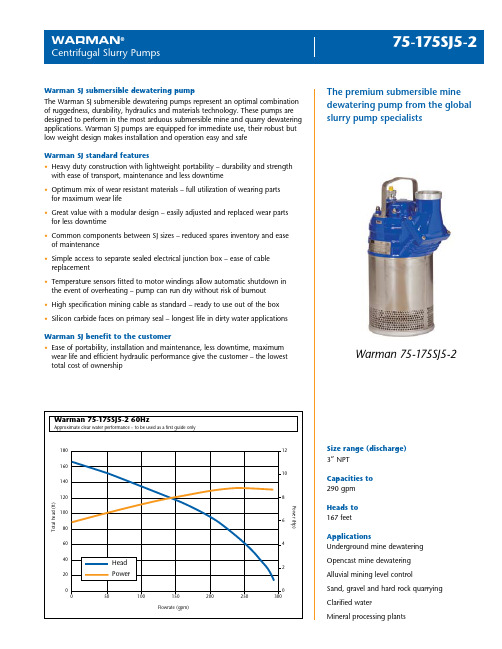
Shaft seal Double mechanical seal in oil bath Primary seal: Silicon carbide on silicon carbide Secondary seal: Stainless steel on antimony treated carbon
80 60 40 20
0 0
12 10
8 6
4
Head
2
Power
0
50
100
150
200
250
300
FFlolowwrate(g(gppmm))
PPoowweer r(H(pH) p)
Size range (discharge) 3” NPT
Capacities to 290 gpm
Heads to 167 feet
Bearings Upper bearing: Single-row deep groove ball bearing Lower bearing: Double angular contact ball bearing
- 1、下载文档前请自行甄别文档内容的完整性,平台不提供额外的编辑、内容补充、找答案等附加服务。
- 2、"仅部分预览"的文档,不可在线预览部分如存在完整性等问题,可反馈申请退款(可完整预览的文档不适用该条件!)。
- 3、如文档侵犯您的权益,请联系客服反馈,我们会尽快为您处理(人工客服工作时间:9:00-18:30)。
拆卸叶轮
拆卸内衬隔板
拆卸密封腔体
拆卸盘根和压盖
拆卸轴套
注意: 如果轴套已磨损而拆卸困难,可能要借助 其它拆卸工具
机械密封的安装
采用集装式密封替代盘根
Hale Waihona Puke 改造的内衬隔板 标准内衬隔板
内衬隔板不加改造仍可完成了机封安装
推荐使用单端面机封
采用标准内衬隔板即可完成了机封的安装
推荐采用双端面机封
WARMAN INSTALLATION PROCEDURE
WARMAN泵的安装程序
完整安装机械密封部件
AVAILABLE EITHER RUBBER OR METAL LINED PACKED GLAND OR EXPELLER
首先拆下泵盖
拆下前端盖垫片
注意 : 最好将泵盖和端盖垫片 这两部件一起拆下
