JPG文件结构
jpg 文件格式详解
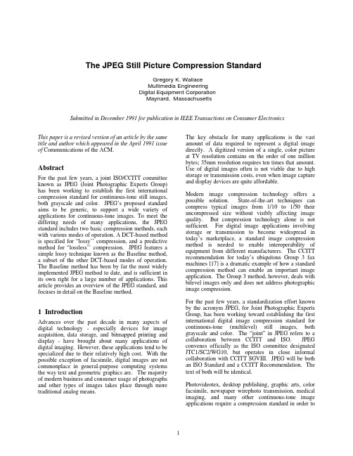
This paper is a revised version of an article by the same title and author which appeared in the April 1991 issue of Communications of the ACM.AbstractFor the past few years, a joint ISO/CCITT committee known as JPEG (Joint Photographic Experts Group) has been working to establish the first international compression standard for continuous-tone still images, both grayscale and color. JPEG’s proposed standard aims to be generic, to support a wide variety of applications for continuous-tone images. To meet the differing needs of many applications, the JPEG standard includes two basic compression methods, each with various modes of operation. A DCT-based method is specified for “lossy’’ compression, and a predictive method for “lossless’’ compression. JPEG features a simple lossy technique known as the Baseline method, a subset of the other DCT-based modes of operation. The Baseline method has been by far the most widely implemented JPEG method to date, and is sufficient in its own right for a large number of applications. This article provides an overview of the JPEG standard, and focuses in detail on the Baseline method.1 IntroductionAdvances over the past decade in many aspects of digital technology - especially devices for image acquisition, data storage, and bitmapped printing and display - have brought about many applications of digital imaging. However, these applications tend to be specialized due to their relatively high cost. With the possible exception of facsimile, digital images are not commonplace in general-purpose computing systems the way text and geometric graphics are. The majority of modern business and consumer usage of photographs and other types of images takes place through more traditional analog means.The key obstacle for many applications is the vast amount of data required to represent a digital image directly. A digitized version of a single, color picture at TV resolution contains on the order of one million bytes; 35mm resolution requires ten times that amount. Use of digital images often is not viable due to high storage or transmission costs, even when image capture and display devices are quite affordable.Modern image compression technology offers a possible solution. State-of-the-art techniques can compress typical images from 1/10 to 1/50 their uncompressed size without visibly affecting image quality. But compression technology alone is not sufficient. For digital image applications involving storage or transmission to become widespread in today’s marketplace, a standard image compression method is needed to enable interoperability of equipment from different manufacturers. The CCITT recommendation for today’s ubiquitous Group 3 fax machines [17] is a dramatic example of how a standard compression method can enable an important image application. The Group 3 method, however, deals with bilevel images only and does not address photographic image compression.For the past few years, a standardization effort known by the acronym JPEG, for Joint Photographic Experts Group, has been working toward establishing the first international digital image compression standard for continuous-tone (multilevel) still images, both grayscale and color. The “joint” in JPEG refers to a collaboration between CCITT and ISO. JPEG convenes officially as the ISO committee designated JTC1/SC2/WG10, but operates in close informal collaboration with CCITT SGVIII. JPEG will be both an ISO Standard and a CCITT Recommendation. The text of both will be identical.Photovideotex, desktop publishing, graphic arts, color facsimile, newspaper wirephoto transmission, medical imaging, and many other continuous-tone image applications require a compression standard in order toThe JPEG Still Picture Compression StandardGregory K. WallaceMultimedia EngineeringDigital Equipment CorporationMaynard, MassachusettsSubmitted in December 1991 for publication in IEEE Transactions on Consumer Electronicsdevelop significantly beyond their present state. JPEG has undertaken the ambitious task of developing ageneral-purpose compression standard to meet the needs of almost all continuous-tone still-image applications.If this goal proves attainable, not only will individual applications flourish, but exchange of images across application boundaries will be facilitated. This latter feature will become increasingly important as more image applications are implemented on general-purpose computing systems, which are themselves becoming increasingly interoperable and internetworked. For applications which require specialized VLSI to meet their compression and decompression speed requirements, a common method will provide economies of scale not possible within a single application.This article gives an overview of JPEG’s proposed image-compression standard. Readers without prior knowledge of JPEG or compression based on the Discrete Cosine Transform (DCT) are encouraged to study first the detailed description of the Baseline sequential codec, which is the basis for all of the DCT-based decoders. While this article provides many details, many more are necessarily omitted. The reader should refer to the ISO draft standard [2] before attempting implementation.Some of the earliest industry attention to the JPEG proposal has been focused on the Baseline sequential codec as a motion image compression method - of the ‘‘intraframe’’ class, where each frame is encoded as a separate image. This class of motion image coding, while providing less compression than ‘‘interframe’’methods like MPEG, has greater flexibility for video editing. While this paper focuses only on JPEG as a still picture standard (as ISO intended), it is interesting to note that JPEG is likely to become a ‘‘de facto’’intraframe motion standard as well.2 Background: Requirements and Selec-tion ProcessJPEG’s goal has been to develop a method for continuous-tone image compression which meets the following requirements:1)be at or near the state of the art with regard tocompression rate and accompanying image fidelity, over a wide range of image quality ratings, and especially in the range where visual fidelity to the original is characterized as “very good” to “excellent”; also, the encoder should be parameterizable, so that the application (or user) can set the desired compression/quality tradeoff;2)be applicable to practically any kind ofcontinuous-tone digital source image (i.e. for most practical purposes not be restricted to images of certain dimensions, color spaces, pixel aspect ratios, etc.) and not be limited to classes of imagery with restrictions on scene content, such as complexity, range of colors, or statistical properties;3)have tractable computational complexity, to makefeasible software implementations with viable performance on a range of CPU’s, as well as hardware implementations with viable cost for applications requiring high performance;4) have the following modes of operation:•Sequential encoding: each image component is encoded in a single left-to-right, top-to-bottomscan;•Progressive encoding: the image is encoded in multiple scans for applications in whichtransmission time is long, and the viewerprefers to watch the image build up in multiplecoarse-to-clear passes;•Lossless encoding: the image is encoded to guarantee exact recovery of every sourceimage sample value (even though the result islow compression compared to the lossymodes);•Hierarchical encoding: the image is encoded at multiple resolutions so that lower-resolutionversions may be accessed without first havingto decompress the image at its full resolution. In June 1987, JPEG conducted a selection process based on a blind assessment of subjective picture quality, and narrowed 12 proposed methods to three. Three informal working groups formed to refine them, and in January 1988, a second, more rigorous selection process [19] revealed that the “ADCT” proposal [11], based on the 8x8 DCT, had produced the best picture quality.At the time of its selection, the DCT-based method was only partially defined for some of the modes of operation. From 1988 through 1990, JPEG undertook the sizable task of defining, documenting, simulating, testing, validating, and simply agreeing on the plethora of details necessary for genuine interoperability and universality. Further history of the JPEG effort is contained in [6, 7, 9, 18].3 Architecture of the Proposed Standard The proposed standard contains the four “modes of operation” identified previously. For each mode, one or more distinct codecs are specified. Codecs within a mode differ according to the precision of source image samples they can handle or the entropy coding method they use. Although the word codec (encoder/decoder) is used frequently in this article, there is no requirement that implementations must include both an encoder and a decoder. Many applications will have systems or devices which require only one or the other.The four modes of operation and their various codecs have resulted from JPEG’s goal of being generic and from the diversity of image formats across applications. The multiple pieces can give the impression of undesirable complexity, but they should actually be regarded as a comprehensive “toolkit” which can span a wide range of continuous-tone image applications. It is unlikely that many implementations will utilize every tool -- indeed, most of the early implementations now on the market (even before final ISO approval) have implemented only the Baseline sequential codec.The Baseline sequential codec is inherently a rich and sophisticated compression method which will be sufficient for many applications. Getting this minimum JPEG capability implemented properly and interoperably will provide the industry with an important initial capability for exchange of images across vendors and applications.4 Processing Steps for DCT-Based Coding Figures 1 and 2 show the key processing steps which are the heart of the DCT-based modes of operation. These figures illustrate the special case of single-component (grayscale) image compression. The reader can grasp the essentials of DCT-based compression by thinking of it as essentially compression of a stream of 8x8 blocks of grayscale image samples. Color image compression can then be approximately regarded as compression of multiple grayscale images, which are either compressed entirely one at a time, or are compressed by alternately interleaving 8x8 sample blocks from each in turn.For DCT sequential-mode codecs, which include the Baseline sequential codec, the simplified diagrams indicate how single-component compression works in a fairly complete way. Each 8x8 block is input, makes its way through each processing step, and yields output in compressed form into the data stream. For DCT progressive-mode codecs, an image buffer exists prior to the entropy coding step, so that an image can be stored and then parceled out in multiple scans with suc-cessively improving quality. For the hierarchical mode of operation, the steps shown are used as building blocks within a larger framework.4.1 8x8 FDCT and IDCTAt the input to the encoder, source image samples are grouped into 8x8 blocks, shifted from unsigned integers with range [0, 2P - 1] to signed integers with range [-2P-1, 2P-1-1], and input to the Forward DCT (FDCT). At the output from the decoder, the Inverse DCT (IDCT) outputs 8x8 sample blocks to form the reconstructed image. The following equations are the idealized mathematical definitions of the 8x8 FDCT and 8x8 IDCT:The DCT is related to the Discrete Fourier Transform (DFT). Some simple intuition for DCT-based compression can be obtained by viewing the FDCT as a harmonic analyzer and the IDCT as a harmonic synthesizer. Each 8x8 block of source image samples is effectively a 64-point discrete signal which is a function of the two spatial dimensions x and y. The FDCT takes such a signal as its input and decomposes it into 64 orthogonal basis signals. Each contains one of the 64 unique two-dimensional (2D) “spatial frequencies’’ which comprise the input signal’s “spectrum.” The ouput of the FDCT is the set of 64 basis-signal amplitudes or “DCT coefficients” whose values are uniquely determined by the particular 64-point input signal.The DCT coefficient values can thus be regarded as the relative amount of the 2D spatial frequencies contained in the 64-point input signal. The coefficient with zero frequency in both dimensions is called the “DC coefficient” and the remaining 63 coefficients are called the “AC coefficients.’’ Because sample values[F(u,v)=14C(u)C(v)7x=07y=0f(x,y)*cos(2x+1)uπ16cos(2x+1)vπ16](1)[f(x,y)=147u=07v=0C(u)C(v)F(u,v)*cos(2x+1)uπ16cos(2x+1)vπ16](2) where:forotherwise.C(u),C(v)=1 2√u,C(u),C(v)=1v=;0typically vary slowly from point to point across an image, the FDCT processing step lays the foundation for achieving data compression by concentrating most of the signal in the lower spatial frequencies. For a typical 8x8 sample block from a typical source image,most of the spatial frequencies have zero or near-zero amplitude and need not be encoded.At the decoder the IDCT reverses this processing step. It takes the 64 DCT coefficients (which at that point have been quantized) and reconstructs a 64-point ouput image signal by summing the basis signals. Mathematically, the DCT is one-to-one mapping for 64-point vectors between the image and the frequency domains. If the FDCT and IDCT could be computed with perfect accuracy and if the DCT coefficients were not quantized as in the following description, the original 64-point signal could be exactly recovered. In principle, the DCT introduces no loss to the source image samples; it merely transforms them to a domain in which they can be more efficiently encoded.Some properties of practical FDCT and IDCT implementations raise the issue of what precisely should be required by the JPEG standard. A fundamental property is that the FDCT and IDCT equations contain transcendental functions. Consequently, no physical implementation can compute them with perfect accuracy. Because of the DCT’s application importance and its relationship to the DFT, many different algorithms by which theFDCT and IDCT may be approximately computed have been devised [16]. Indeed, research in fast DCT algorithms is ongoing and no single algorithm is optimal for all implementations. What is optimal in software for a general-purpose CPU is unlikely to be optimal in firmware for a programmable DSP and is certain to be suboptimal for dedicated VLSI.Even in light of the finite precision of the DCT inputs and outputs, independently designed implementations of the very same FDCT or IDCT algorithm which differ even minutely in the precision by which they represent cosine terms or intermediate results, or in the way they sum and round fractional values, will eventually produce slightly different outputs from identical inputs.To preserve freedom for innovation and customization within implementations, JPEG has chosen to specify neither a unique FDCT algorithm or a unique IDCT algorithm in its proposed standard. This makes compliance somewhat more difficult to confirm,because two compliant encoders (or decoders)generally will not produce identical outputs given identical inputs. The JPEG standard will address this issue by specifying an accuracy test as part of its compliance tests for all DCT-based encoders and decoders; this is to ensure against crudely inaccurate cosine basis functions which would degrade image quality.EntropyDecoderDequantizer IDCTDCT-Based DecoderTable Table Specifications Specifications Compressed Image Data Reconstructed Image DataFigure 1. DCT-Based Encoder Processing StepsFigure 2. DCT-Based Decoder Processing StepsFor each DCT-based mode of operation, the JPEG proposal specifies separate codecs for images with 8-bit and 12-bit (per component) source image samples. The 12-bit codecs, needed to accommodate certain types of medical and other images, require greater computational resources to achieve the required FDCT or IDCT accuracy. Images with other sample precisions can usually be accommodated by either an 8-bit or 12-bit codec, but this must be done outside the JPEG standard. For example, it would be the responsibility of an application to decide how to fit or pad a 6-bit sample into the 8-bit encoder’s input interface, how to unpack it at the decoder’s output, and how to encode any necessary related information.4.2 QuantizationAfter output from the FDCT, each of the 64 DCT coefficients is uniformly quantized in conjunction with a 64-element Quantization Table, which must be specified by the application (or user) as an input to the encoder. Each element can be any integer value from 1to 255, which specifies the step size of the quantizer for its corresponding DCT coefficient. The purpose of quantization is to achieve further compression by representing DCT coefficients with no greater precision than is necessary to achieve the desired image quality. Stated another way, the goal of this processing step is to discard information which is not visually significant.Quantization is a many-to-one mapping, and therefore is fundamentally lossy. It is the principal source of lossiness in DCT-based encoders.Quantization is defined as division of each DCT coefficient by its corresponding quantizer step size,followed by rounding to the nearest integer:F Q (u ,v ) = Integer Round ( F (u ,v )Q (u ,v) )(3)This output value is normalized by the quantizer step size. Dequantization is the inverse function, which in this case means simply that the normalization is removed by multiplying by the step size, which returns the result to a representation appropriate for input to the IDCT:When the aim is to compress the image as much as possible without visible artifacts, each step size ideally should be chosen as the perceptual threshold or “just noticeable difference” for the visual contribution of its corresponding cosine basis function. These thresholds are also functions of the source image characteristics,display characteristics and viewing distance. For applications in which these variables can be reasonably well defined, psychovisual experiments can be performed to determine the best thresholds. The experiment described in [12] has led to a set of Quantization Tables for CCIR-601 [4] images and displays. These have been used experimentally by JPEG members and will appear in the ISO standard as a matter of information, but not as a requirement.4.3 DC Coding and Zig-Zag SequenceAfter quantization, the DC coefficient is treated separately from the 63 AC coefficients. The DC coefficient is a measure of the average value of the 64image samples. Because there is usually strong correlation between the DC coefficients of adjacent 8x8blocks, the quantized DC coefficient is encoded as the difference from the DC term of the previous block in the encoding order (defined in the following), as shown in Figure 3. This special treatment is worthwhile, as DC coefficients frequently contain a significant fraction of the total image energy.F Q (u ,v ) =F Q(u ,v )Q (u ,v )*(4). . .DIFF = DC i - DC i-1i-1iDifferential DC encoding Zig−zag sequence. . .770770Figure 3. Preparation of Quantized Coefficients for Entropy CodingFinally, all of the quantized coefficients are ordered into the “zig-zag” sequence, also shown in Figure 3. This ordering helps to facilitate entropy coding by placing low-frequency coefficients (which are more likely to be nonzero) before high-frequency coefficients.4.4 Entropy CodingThe final DCT-based encoder processing step is entropy coding. This step achieves additional compression losslessly by encoding the quantized DCT coefficients more compactly based on their statistical characteristics. The JPEG proposal specifies two entropy coding methods - Huffman coding [8] and arithmetic coding [15]. The Baseline sequential codec uses Huffman coding, but codecs with both methods are specified for all modes of operation.It is useful to consider entropy coding as a 2-step process. The first step converts the zig-zag sequence of quantized coefficients into an intermediate sequence of symbols. The second step converts the symbols to a data stream in which the symbols no longer have externally identifiable boundaries. The form and definition of the intermediate symbols is dependent on both the DCT-based mode of operation and the entropy coding method.Huffman coding requires that one or more sets of Huffman code tables be specified by the application. The same tables used to compress an image are needed to decompress it. Huffman tables may be predefined and used within an application as defaults, or computed specifically for a given image in an initial statistics-gathering pass prior to compression. Such choices are the business of the applications which use JPEG; the JPEG proposal specifies no required Huffman tables. Huffman coding for the Baseline sequential encoder is described in detail in section 7.By contrast, the particular arithmetic coding method specified in the JPEG proposal [2] requires no tables to be externally input, because it is able to adapt to the image statistics as it encodes the image. (If desired, statistical conditioning tables can be used as inputs for slightly better efficiency, but this is not required.) Arithmetic coding has produced 5-10% better compression than Huffman for many of the images which JPEG members have tested. However, some feel it is more complex than Huffman coding for certain implementations, for example, the highest-speed hardware implementations. (Throughout JPEG’s history, “complexity” has proved to be most elusive as a practical metric for comparing compression methods.) If the only difference between two JPEG codecs is the entropy coding method, transcoding between the two is possible by simply entropy decoding with one method and entropy recoding with the other.4.5 Compression and Picture QualityFor color images with moderately complex scenes, all DCT-based modes of operation typically produce the following levels of picture quality for the indicated ranges of compression. These levels are only a guideline - quality and compression can vary significantly according to source image characteristics and scene content. (The units “bits/pixel” here mean the total number of bits in the compressed image -including the chrominance components - divided by the number of samples in the luminance component.)•0.25-0.5 bits/pixel: moderate to good quality, sufficient for some applications;•0.5-0.75 bits/pixel: good to very good quality, sufficient for many applications;•0.75-1/5 bits/pixel: excellent quality, sufficient for most applications;• 1.5-2.0 bits/pixel: usually indistinguishable from the original, sufficient for the most demanding applications.5 Processing Steps for Predictive Lossless CodingAfter its selection of a DCT-based method in 1988, JPEG discovered that a DCT-based lossless mode was difficult to define as a practical standard against which encoders and decoders could be independently implemented, without placing severe constraints on both encoder and decoder implementations.JPEG, to meet its requirement for a lossless mode of operation, has chosen a simple predictive method which is wholly independent of the DCT processing described previously. Selection of this method was not the result of rigorous competitive evaluation as was the DCT-based method. Nevertheless, the JPEG lossless method produces results which, in light of its simplicity, are surprisingly close to the state of the art for lossless continuous-tone compression, as indicated by a recent technical report [5].Figure 4 shows the main processing steps for a single-component image. A predictor combines the values of up to three neighboring samples (A, B, and C) to form a prediction of the sample indicated by X in Figure 5. This prediction is then subtracted from the actual value of sample X, and the difference is encodedlosslessly by either of the entropy coding methods -Huffman or arithmetic. Any one of the eight predictors listed in Table 1 (under “selection-value”) can be used.Selections 1, 2, and 3 are one-dimensional predictors and selections 4, 5, 6 and 7 are two-dimensional predictors. Selection-value 0 can only be used for differential coding in the hierarchical mode of operation. The entropy coding is nearly identical to that used for the DC coefficient as described in section 7.1 (for Huffman coding).For the lossless mode of operation, two different codecs are specified - one for each entropy coding method. The encoders can use any source image precision from 2 to 16 bits/sample, and can use any of the predictors except selection-value 0. The decoders must handle any of the sample precisions and any of the predictors. Lossless codecs typically produce around 2:1compression for color images with moderately complex scenes.Figure 5. 3-Sample Prediction Neighborhood C B A X6 Multiple-Component ImagesThe previous sections discussed the key processing steps of the DCT-based and predictive lossless codecs for the case of single-component source images. These steps accomplish the image data compression. But a good deal of the JPEG proposal is also concerned with the handling and control of color (or other) images with multiple components. JPEG’s aim for a generic compression standard requires its proposal to accommodate a variety of source image formats.6.1 Source Image FormatsThe source image model used in the JPEG proposal is an abstraction from a variety of image types and applications and consists of only what is necessary to compress and reconstruct digital image data. The reader should recognize that the JPEG compressed data format does not encode enough information to serve as a complete image representation. For example, JPEG does not specify or encode any information on pixel aspect ratio, color space, or image acquisition characteristics.Table 1. Predictors for Lossless Codingselection-valueprediction 0no prediction 1234567A B CA+B-CA+((B-C)/2)B+((A-C)/2)(A+B)/2PredictorEntropy EncoderLossless EncoderSource Image DataTable SpecificationsCompressed Image DataFigure 4. Lossless Mode Encoder Processing StepsFigure 6 illustrates the JPEG source image model. A source image contains from 1 to 255 image components, sometimes called color or spectral bands or channels. Each component consists of a rectangular array of samples. A sample is defined to be an unsigned integer with precision P bits, with any value in the range [0, 2P -1]. All samples of all components within the same source image must have the same precision P. P can be 8 or 12 for DCT-based codecs,and 2 to 16 for predictive codecs.The ith component has sample dimensions x i by y i . To accommodate formats in which some image components are sampled at different rates than others,components can have different dimensions. The dimensions must have a mutual integral relationship defined by H i and V i , the relative horizontal and vertical sampling factors, which must be specified for each component. Overall image dimensions X and Y are defined as the maximum x i and y i for all components in the image, and can be any number up to 216. H and V are allowed only the integer values 1through 4. The encoded parameters are X, Y, and H i s and V i s for each components. The decoder reconstructs the dimensions x i and y i for each component, according to the following relationship shown in Equation 5:where is the ceiling function.6.2 Encoding Order and InterleavingA practical image compression standard must address how systems will need to handle the data during the process of decompression. Many applications need to pipeline the process of displaying or printing multiple-component images in parallel with the processx i = X H i H andy i =Y V i V maxm ax ××(5)of decompression. For many systems, this is onlyfeasible if the components are interleaved together within the compressed data stream.To make the same interleaving machinery applicable to both DCT-based and predictive codecs, the JPEG proposal has defined the concept of “data unit.” A data unit is a sample in predictive codecs and an 8x8 block of samples in DCT-based codecs.The order in which compressed data units are placed in the compressed data stream is a generalization of raster-scan order. Generally, data units are ordered from left-to-right and top-to-bottom according to the orientation shown in Figure 6. (It is the responsibility of applications to define which edges of a source image are top, bottom, left and right.) If an image component is noninterleaved (i.e., compressed without being interleaved with other components), compressed data units are ordered in a pure raster scan as shown in Figure 7.When two or more components are interleaved, each component C i is partitioned into rectangular regions of H i by V i data units, as shown in the generalized example of Figure 8. Regions are ordered within a component from left-to-right and top-to-bottom, and within a region, data units are ordered from left-to-right and top-to-bottom. The JPEG proposal defines the term Minimum Coded Unit (MCU) to be the smallestright bottomleftFigure 7. Noninterleaved Data Orderingtopline(a) Source image with multiple components C Figure 6. JPEG Source Image Model(b) Characteristics of an image componentC Nf。
13 BMP、JPG、DICOM文件

(1) 图像开始SOI(Start of Image) 标记结构 字节数 0XFF 1 0XD8 1 可作为JPEG格式的判据(JFIF(JPEG File Interchange Format)还需要APP0的配合)
(7) 扫描线开始SOS(Start of Scan) 标记结构 字节数 意义 0XFF 1 0XDA 1 Ls 2 SOS标记码长度,不包括前两个字节0XFF,0XDA Ns 1 Cs1 1 (Td1,Ta1) 1 Cs2 1 (Td2,Ta2) 1 … CsNs 1 (TdNs,TaNs) 1 Ss 1 Se 1 (Ah,Al) 1 压缩图像数据 Ns为Scan中成分的个数,在基本系统中,Ns=Nf(Frame中成分个数)。CSNs 为在Scan中成分的编号。TdNs为高4位,TaNs为低4位,分别表示DC和AC编码 表的编号。在基本系统中Ss=0,Se=63,Ah=0,Al=0。
(6) 霍夫曼(Huffman)表DHT(Define Huffman Table) 标记结构 0XFF 0XC4 Lh (Tc,Th) L1 L2 … L16 V1 V2 … Vt 字节数 1 1 2 1 1 1 16组数据中,每组个数 1 1 1 每个代码值;t=L1+L2+…L16 1 意义
(4)DRI(Define Restart Interval) 此标记需要用到最小编码单元(MCU,Minimum Coding Unit)的概念。前面提到,Y 分量数据重要,UV分量的数据相对不重要,所以可以只取UV的一部分,以增加压 缩比。目前支持JPEG格式的软件通常提供两种取样方式YUV411和YUV422,其含 义是YUV三个分量的数据取样比例。举例来说,如果Y取四个数据单元,即水平取 样因子Hy乘以垂直取样因子Vy的值为4,而U和V各取一个数据单元,即 Hu×Vu=1,Hv×Vv=1。那么这种部分取样就称为YUV411。
JPG,png,GIF,BMP四种常见图像格式的对比

JPG,png,GIF,BMP四种常见图像格式的对⽐JPG(JPEG)JPEG 图⽚以 24 位颜⾊存储单个光栅图像。
JPEG是与平台⽆关的格式,⽀持最⾼级别的压缩,不过,这种压缩是有损耗的。
渐近式JPEG ⽂件⽀持交错。
可以提⾼或降低 JPEG⽂件压缩的级别。
但是,⽂件⼤⼩是以图像质量为代价的。
压缩⽐率可以⾼达 100:1。
(JPEG 格式可在 10:1 到20:1的⽐率下轻松地压缩⽂件,⽽图⽚质量不会下降。
)JPEG压缩可以很好地处理写实摄影作品。
但是,对于颜⾊较少、对⽐级别强烈、实⼼边框或纯⾊区域⼤的较简单的作品,JPEG压缩⽆法提供理想的结果。
有时,压缩⽐率会低到 5:1,严重损失了图⽚完整性。
这⼀损失产⽣的原因是,JPEG压缩⽅案可以很好地压缩类似的⾊调,但是 JPEG 压缩⽅案不能很好地处理亮度的强烈差异或处理纯⾊区域。
优点: 摄影作品或写实作品⽀持⾼级压缩。
利⽤可变的压缩⽐可以控制⽂件⼤⼩。
⽀持交错(对于渐近式 JPEG ⽂件)。
⼴泛⽀持 Internet 标准。
缺点: 有损耗压缩会使原始图⽚数据质量下降。
当您编辑和重新保存 JPEG ⽂件时,JPEG会混合原始图⽚数据的质量下降。
这种下降是累积性的。
JPEG不适⽤于所含颜⾊很少、具有⼤块颜⾊相近的区域或亮度差异⼗分明显的较简单的图⽚。
jpg格式是⼀种图⽚格式,使⼀种⽐较常见的图画格式,如果你的图⽚是其他格式的话,你可以通过以下⽅法转化:1、photoshop,打开图画以后,按另存为,下⾯格式那⾥选择JPG格式就是了,这个⽅法⽐较简单,⽽且适合画质⽐较好的,要求⽐较⾼的图⽚转换。
2、如果你要求不⾼,你直接通过windows附带的图画程序,选择JPG格式就⾏了,这个来转换的话,画质嘛,马马虎虎,不过在⽹上嘛,过得去了!如果JPG格式转其他格式,这样的⽅法同样适⽤。
JPEG (Joint PhotographicExperts GROUP)是由国际标准组织(ISO:InternationalStandardization Organization)和国际电话电报咨询委员会(CCITT:ConsultationCommitee of the International Telephone andTelegraph)为静态图像所建⽴的第⼀个国际数字图像压缩标准,也是⾄今⼀直在使⽤的、应⽤最⼴的图像压缩标准。
JPG文件结构分析
JPG文件结构分析JPG(Joint Photographic Experts Group)是一种常见的图像文件格式,以其高压缩比和图像质量而闻名。
在本文中,将对JPG文件的结构进行分析。
1.文件头:JPG文件头部包含固定的标识符,用于识别文件类型。
通常,JPG文件的文件头为16个字节,其中包括"FFD8"的起始标志。
2.数据段:JPG文件的数据段是由多个标记组成的。
每个标记都由两个字节的起始标志"FF"和一个标记标识符组成。
标记标识符指示了将要跟随的数据类型或操作。
数据段中常见的标记包括APP0、DQT、SOF0、DHT、SOS等。
其中,APP0标记包含一些额外的信息,如JFIF(JPEG文件交换格式)版本号和文件创作的设备。
DQT(量化表定义)标记包含了量化表,这些表用于调整图像的颜色分辨率。
SOF0(帧头)标记包含了图像的宽度、高度以及色彩模式等信息。
DHT(霍夫曼表定义)标记包含了JPEG压缩算法所使用的霍夫曼编码表。
SOS(扫描开始)标记表示图像的实际数据开始。
3.图像数据:JPG文件的图像数据是压缩后的二进制流。
图像数据通常由几个扫描组成,每个扫描都由一个起始标记和相应的数据组成。
扫描包含的数据进行了特殊的编码处理,以实现高压缩比。
压缩算法主要包括离散余弦变换和霍夫曼编码。
在离散余弦变换中,图像被划分成8x8的块,每个块进行离散余弦变换,然后进行量化。
量化后的数据通过霍夫曼编码进行压缩。
4.文件尾:JPG文件尾部由一个16位的结束标记"FFD9"组成,用于表示图像数据的结束。
在JPG文件结构中,数据段是最重要的部分。
它包含了图像的所有信息,包括压缩参数、颜色信息和压缩后的图像数据。
图像数据经过JPEG压缩算法,可以有效地减小文件大小,并保持较高的图像质量。
总结起来,JPG文件的结构包括文件头、数据段、图像数据和文件尾。
数据段是JPG文件最重要的部分,包含了图像的所有信息和压缩后的图像数据。
什么是 jpg(jpeg) 文件?如何打开、编辑和转换 jpg(jpeg) 文件
什么是JPG(JPEG) 文件?如何打开、编辑和转换JPG(JPEG) 文件要知道什么•JPG/JPEG 文件是图像文件。
•使用任何网页浏览器或图像查看器打开一个。
•转换成PNG,SVG,PDF等与图像转换工具。
这里将解释JPG 和JPEG 文件是什么,以及它们与其他图像格式有何不同、如何打开一种文件以及哪些程序可以将一种文件转换为不同的图像格式,例如SVG、GIF 或PNG。
什么是JPG (JPEG) 文件?JPG 或JPEG 文件是图像文件。
虽然一些JPG 图像文件使用 .JPG 文件扩展名,而另一些使用 .JPEG,但它们都是相同类型的文件。
一些JPEG 图像文件使用 .JPE 文件扩展名,但这并不常见。
JFIF 文件是也使用JPEG 压缩的JPEG 文件交换格式文件,但它们不如JPG 文件流行。
如何打开JPG 或JPEG 文件所有图像查看器和编辑器都支持JPG 文件。
它是最广泛接受的图像格式。
您可以使用Web 浏览器(如Chrome 或百度浏览器)打开JPG 文件(将本地JPG 文件拖到浏览器窗口),以及内置的Microsoft 程序(如照片查看器和画图应用程序)。
如果您使用的是Mac,Apple Preview 和Apple 照片可以打开JPG 文件。
JPG 文件被广泛使用,因为压缩算法显着减小了文件的大小,非常适合在网站上共享、存储和显示。
但是,这种JPG 压缩也会降低图像的质量,如果它被高度压缩,这可能会很明显。
Adobe Photoshop以及基本上任何其他查看图像的程序,包括Google Drive等在线服务,也支持JPG 文件。
移动设备也支持打开JPG 文件,这意味着您可以在电子邮件和短信中查看它们,而无需特定的JPG 查看应用程序。
除非具有正确的文件扩展名,否则某些网站和程序可能无法将图像识别为JPEG 图像文件。
例如,一些基本的图像编辑器和查看器只会打开 .JPG 文件,而不会知道您拥有的 .JPEG 文件是同一个东西。
jpg编码

一、JPEG文件格式介绍JPEG文件使用的数据存储方式有多种。
最常用的格式称为JPEG文件交换格式(JPEG File Interchange Format,JFIF)。
而JPEG文件大体上可以分成两个部分:标记码(Tag)和压缩数据。
标记码由两个字节构成,其前一个字节是固定值0xFF,后一个字节则根据不同意义有不同数值。
在每个标记码之前还可以添加数目不限的无意义的0xFF填充,也就说连续的多个0xFF 可以被理解为一个0xFF,并表示一个标记码的开始。
而在一个完整的两字节的标记码后,就是该标记码对应的压缩数据流,记录了关于文件的诸种信息。
常用的标记有SOI、APP0、DQT、SOF0、DHT、DRI、SOS、EOI。
SOI,Start of Image,图像开始标记代码2字节固定值0xFFD8APP0,Application,应用程序保留标记0标记代码2字节固定值0xFFE0包含9个具体字段:①数据长度2字节①~⑨9个字段的总长度②标识符5字节固定值0x4A46494600,即字符串“JFIF0”③版本号2字节一般是0x0102,表示JFIF的版本号1.2④X和Y的密度单位1字节只有三个值可选i.0:无单位;1:点数/英寸;2:点数/厘米⑤X方向像素密度2字节取值范围未知⑥Y方向像素密度2字节取值范围未知⑦缩略图水平像素数目1字节取值范围未知⑧缩略图垂直像素数目1字节取值范围未知⑨缩略图RGB位图长度可能是3的倍数缩略图RGB位图数据本标记段可以包含图像的一个微缩版本,存为24位的RGB像素。
如果没有微缩图像(这种情况更常见),则字段⑦“缩略图水平像素数目”和字段⑧“缩略图垂直像素数目”的值均为0。
APPn,Application,应用程序保留标记n,其中n=1~15(任选)标记代码2字节固定值0xFFE1~0xFFF包含2个具体字段:①数据长度2字节①~②2个字段的总长度i.即不包括标记代码,但包括本字段②详细信息数据长度-2字节内容不定例如,Adobe Photoshop生成的JPEG图像中就用了APP1和APP13两个标记段分别存储了一幅图像的副本。
JPG图片文件结构分析.docx

JPG文件结构分析2010-04-06 22:32【转自网络作者:一江秋水】一、简述JPEG是一个压缩标准,又可分为标准 JPEG、渐进式JPEG及JPEG2000三种:①标准JPEG:以24位颜色存储单个光栅图像,是与平台无关的格式,支持最高级别的压缩,不过,这种压缩是有损耗的。
此类型图片在网页下载时只能由上而下依序显示图片,直到图片资料全部下载完毕,才能看到全貌。
②渐进式 JPEG:渐进式JPG为标准JPG的改良格式,支持交错,可以在网页下载时,先呈现出图片的粗略外观后,再慢慢地呈现出完整的内容,渐进式JPG的文件比标准JPG的文件要来得小。
③JPEG2000:新一代的影像压缩法,压缩品质更好,其压缩率比标准JPEG高约30%左右,同时支持有损和无损压缩。
一个极其重要的特征在于它能实现渐进传输,即先传输图像的轮廓,然后逐步传输数据,让图像由朦胧到清晰显示。
以一幅24 位彩色图像为例,JPEG的压缩分为四个步骤:①颜色转换:在将彩色图像进行压缩之前,必须先对颜色模式进行数据转换。
转换完成之后还需要进行数据采样。
②DCT变换:是将图像信号在频率域上进行变换,分离出高频和低频信息的处理过程,然后再对图像的高频部分(即图像细节)进行压缩。
首先以象素为单位将图像划分为多个8×8的矩阵,然后对每一个矩阵作DCT 变换。
把8×8的象素矩阵变成8×8的频率系数矩阵(所谓频率就是颜色改变的速度),频率系数都是浮点数。
③量化:由于下面第四步编码过程中使用的码本都是整数,因此要对频率系数进行量化,将之转换为整数。
数据量化后,矩阵中的数据都是近似值,和原始图像数据之间有了差异,这一差异是造成图像压缩后失真的主要原因。
这一过程中,质量因子的选取至为重要。
值选得大,可以大幅度提高压缩比,但是图像质量就比较差,质量因子越小图像重建质量越好,但是压缩比越低。
④编码:编码是基于统计特性的方法。
四个步骤都完成后的JPEG文件,其基本数据结构为两大类型:“段”和经过压缩编码的图像数据。
JPG文件结构分析

JPEG是一个压缩标准,又可分为标准 JP EG、渐进式JPEG及JPEG2000三种:①标准JPE G:以24位颜色存储单个光栅图像,是与平台无关的格式,支持最高级别的压缩,不过,这种压缩是有损耗的。
此类型图片在网页下载时只能由上而下依序显示图片,直到图片资料全部下载完毕,才能看到全貌。
②渐进式 JPEG:渐进式J PG为标准JPG的改良格式,支持交错,可以在网页下载时,先呈现出图片的粗略外观后,再慢慢地呈现出完整的内容,渐进式JPG的文件比标准JPG的文件要来得小。
③JPEG2000:新一代的影像压缩法,压缩品质更好,其压缩率比标准JP EG高约30%左右,同时支持有损和无损压缩。
一个极其重要的特征在于它能实现渐进传输,即先传输图像的轮廓,然后逐步传输数据,让图像由朦胧到清晰显示。
以一幅24 位彩色图像为例,JPEG的压缩分为四个步骤:①颜色转换:在将彩色图像进行压缩之前,必须先对颜色模式进行数据转换。
转换完成之后还需要进行数据采样。
②D CT 变换:是将图像信号在频率域上进行变换,分离出高频和低频信息的处理过程,然后再对图像的高频部分(即图像细节)进行压缩。
首先以象素为单位将图像划分为多个8×8的矩阵,然后对每一个矩阵作D CT 变换。
把8×8的象素矩阵变成8×8的频率系数矩阵(所谓频率就是颜色改变的速度),频率系数都是浮点数。
③量化:由于下面第四步编码过程中使用的码本都是整数,因此要对频率系数进行量化,将之转换为整数。
数据量化后,矩阵中的数据都是近似值,和原始图像数据之间有了差异,这一差异是造成图像压缩后失真的主要原因。
JPEG图片文件编解码详解
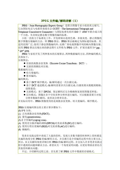
JPEG文件编/解码详解(1)2.初步了解图像数据流的结构1)理论说明分析图像数据流的结构,笔者准备以一个从宏观到微观的顺序为读者详细剖析,即:数据流→最小编码单元→数据单元与颜色分量。
a)在图片像素数据流中,信息可以被分为一段接一段的最小编码单元(Minimum Coded Unit,MCU)数据流。
所谓MCU,是图像中一个正方矩阵像素的数据。
矩阵的大小是这样确定的:查阅标记SOF0,可以得到图像不同颜色分量的采样因子,即Y、Cr、Cb三个分量各自的水平采样因子和垂直采样因子。
大多图片的采样因子为4:1:1或1:1:1。
其中,4:1:1即(2*2):(1*1):(1*1));1:1:1即(1*1):(1*1):(1*1)。
记三个分量中水平采样因子最大值为Hmax,垂直采样因子最大值为Vmax,那么单个MCU矩阵的宽就是Hmax*8像素,高就是Vmax*8像素。
如果,整幅图像的宽度和高度不是MCU宽度和高度的整数倍,那么编码时会用某些数值填充进去,保证解码过程中MCU的完整性(解码完成后,可直接忽视图像宽度和高度外的数据)。
在数据流中,MCU的排列方法是从左到右,从上到下。
b)每个MCU又分为若干个数据单元。
数据单元的大小必定为8*8,所以每个MCU的数据单元个数为Hmax*Vmax。
另外JPEG的压缩方法与BMP文件有所不同,它不是把每个像素的颜色分量连续存储在一起的,而是把图片分成Y,Cr,Cb三张子图,然后分别压缩。
而三个颜色分量的采样密度(即采样因子)可能一样(例如1:1:1)也可能不一样(例如4:1:1)。
每个MCU内部,数据的顺序是Y、Cr、Cb。
如果一个颜色分量有多个数据单元,则顺序是从左到右,从上到下。
2)举例说明下面通过一幅32*35的图像,对上面两个问题列出两种采样因子的具体说明。
图1 整张完整的图像(4:1:1)图2 将图像的MCU1放大图1及图3中灰色部分为实际图像大小(32px*35px);粗虚线表示各个MCU的分界;细虚线表示MCU内部数据单元的分界。
JPG图片文件结构分析
JPG文件结构分析2010-04-06 22:32【转自网络 作者:一 江秋水】一、简述JPEG是一个压缩标准,又可分为标准 JPEG、渐进式JPEG及JPEG2000三种:①标准JPEG:以24位颜色存储单个光栅图像,是与平台无关的格式,支持最高级 别的压缩,不过,这种压缩是有损耗的。
此类型图片在网页下载时只能由上而下依序显示图片,直到图片资料全部下载完毕,才能看到全貌。
②渐进式 JPEG:渐进式JPG为标准JPG的改良格式,支持交错,可以在网页下载时,先呈现出图片的粗略外观后,再慢慢地呈现出完整的内容,渐进式JPG的文件 比标准JPG的文件要来得小。
③JPEG2000:新一代的影像压缩法,压缩品质更好,其压缩率比标准JPEG高约30%左右,同时支持有损 和无损压缩。
一个极其重要的特征在于它能实现渐进传输,即先传输图像的轮廓,然后逐步传输数据,让图像由朦胧到清晰显示。
以一幅24 位彩色图像为例,JPEG的压缩分为四个步骤:①颜色转换:在将彩色图像进行压缩之前,必须先对颜色模式进行数据转换。
转换完成之后 还需要进行数据采样。
②DCT 变换:是将图像信号在频率域上进行变换,分离出高频和低频信息的处理过程,然后再对图像的高频部分(即图像细 节)进行压缩。
首先以象素为单位将图像划分为多个8×8的矩阵,然后对每一个矩阵作DCT 变换。
把8×8的象素矩阵变成8×8的频率系数矩阵(所谓频率 就是颜色改变的速度),频率系数都是浮点数。
③量化:由于下面第四步编码过程中使用的码本都是整数,因此要对频率系数进行量化,将之转换为整 数。
数据量化后,矩阵中的数据都是近似值,和原始图像数据之间有了差异,这一差异是造成图像压缩后失真的主要原因。
这一过程中,质量因子的选取至为重要。
值选得大,可以大幅度提高压缩比,但是图像质量就比较差,质量因子越小图像重建质量越好,但是压缩比越低。
④编码:编码是基于统计特性的方 法。
psd.jpg.tiff.bmp.ai.cda.dwg之间的区别和用途
psd.jpg.tiff.bmp.ai.cda.dwg之间的区别跟用途一、PSD文件格式JPEG格式是目前网络上最流行的图像格式,是可以把文件压缩到最小的格式,在 Photoshop软件中以JPEG格式储存时,提供11级压缩级别,以0—10级表示。
其中0级压缩比最高,图像品质最差。
即使采用细节几乎无损的10 级质量保存时,压缩比也可达 5:1。
以BMP格式保存时得到4.28MB图像文件,在采用JPG格式保存时,其文件仅为178KB,压缩比达到24:1。
经过多次比较,采用第8级压缩为存储空间与图像质量兼得的最佳比例。
二、JPG文件格式JPG即JEPGJPEG格式的应用非常广泛,特别是在网络和光盘读物上,都能找到它的身影。
目前各类浏览器均支持JPEG这种图像格式,因为JPEG格式的文件尺寸较小,下载速度快。
这是Photoshop图像处理软件的专用文件格式,文件扩展名是.psd,可以支持图层、通道、蒙板和不同色彩模式的各种图像特征,是一种非压缩的原始文件保存格式。
扫描仪不能直接生成该种格式的文件。
PSD文件有时容量会很大,但由于可以保留所有原始信息,在图像处理中对于尚未制作完成的图像,选用 PSD格式保存是最佳的选择。
JPEG格式是目前网络上最流行的图像格式,是可以把文件压缩到最小的格式,在 Photoshop 软件中以JPEG格式储存时,提供11级压缩级别,以0—10级表示。
其中0级压缩比最高,图像品质最差。
即使采用细节几乎无损的10 级质量保存时,压缩比也可达 5:1。
以BMP格式保存时得到4.28MB图像文件,在采用JPG格式保存时,其文件仅为178KB,压缩比达到24:1。
经过多次比较,采用第8级压缩为存储空间与图像质量兼得的最佳比例。
JPEG格式的应用非常广泛,特别是在网络和光盘读物上,都能找到它的身影。
目前各类浏览器均支持JPEG这种图像格式,因为JPEG格式的文件尺寸较小,下载速度快。
三、TIFF文件格式TIFF (TaglmageFileFormat)图像文件是由Aldus和Microsoft公司为桌上出版系统研制开发的一种较为通用的图像文件格式。
jpeg文件数据结构以及将位图保存为jpg的代码

jpeg文件数据结构以及将位图保存为jpg的代码JPEG文件数据结构以及将位图保存为JPG的代码一、简述JPEG是一个压缩标准,又可分为标准JPEG、渐进式JPEG及JPEG2000三种:①标准JPEG:以24位颜色存储单个光栅图像,是与平台无关的格式,支持最高级别的压缩,不过,这种压缩是有损耗的。
此类型图片在网页下载时只能由上而下依序显示图片,直到图片资料全部下载完毕,才能看到全貌。
②渐进式JPEG:渐进式JPG为标准JPG的改良格式,支持交错,可以在网页下载时,先呈现出图片的粗略外观后,再慢慢地呈现出完整的内容,渐进式JPG的文件比标准JPG 的文件要来得小。
③JPEG2000:新一代的影像压缩法,压缩品质更好,其压缩率比标准JPEG高约30%左右,同时支持有损和无损压缩。
一个极其重要的特征在于它能实现渐进传输,即先传输图像的轮廓,然后逐步传输数据,让图像由朦胧到清晰显示。
以一幅24位彩色图像为例,JPEG的压缩分为四个步骤:①颜色转换:在将彩色图像进行压缩之前,必须先对颜色模式进行数据转换。
转换完成之后还需要进行数据采样。
②DCT 变换:是将图像信号在频率域上进行变换,分离出高频和低频信息的处理过程,然后再对图像的高频部分(即图像细节)进行压缩。
首先以象素为单位将图像划分为多个8×8的矩阵,然后对每一个矩阵作DCT 变换。
把8×8的象素矩阵变成8×8的频率系数矩阵(所谓频率就是颜色改变的速度),频率系数都是浮点数。
③量化:由于下面第四步编码过程中使用的码本都是整数,因此要对频率系数进行量化,将之转换为整数。
数据量化后,矩阵中的数据都是近似值,和原始图像数据之间有了差异,这一差异是造成图像压缩后失真的主要原因。
这一过程中,质量因子的选取至为重要。
值选得大,可以大幅度提高压缩比,但是图像质量就比较差,质量因子越小图像重建质量越好,但是压缩比越低。
④编码:编码是基于统计特性的方法。
JPEG图片格式简单分析
对于花花绿绿色彩斑斓的图片,也许里面包含了艺术家的许多心血,但归根结底它就是一个文件,里面写满了16进制代码的一个文件,这些代码的前面一部分可能是介绍了这张图片的一些简单的信息,后面一大部分是它的图像数据。
这个文件的原理简单的就像是一篇小论文,题目,摘要,关键词,正文,参考文献等,那么这篇小论文的具体格式到底是什么呢?其实很简单,用ultraEdit随便打开一张jpg格式的图片就可以看到,但是要看懂里面的内容也不是一件很容易的事情,那么先看下面转载的这篇文章吧,看完它就会很容易理解JPG的文件格式了。
JPEG 图片格式简单分析1、基本常识微处理机中的存放顺序有正序(big endian)和逆序(little endian)之分。
正序存放就是高字节存放在前低字节在后,而逆序存放就是低字节在前高字节在后。
例如,十六进制数为A02B,正序存放就是A02B,逆序存放就是2BA0。
摩托罗拉(Motorola)公司的微处理器使用正序存放,而英特尔(Intel)公司的微处理器使用逆序。
JPEG文件中的字节是按照正序排列的。
JPEG委员会在制定JPEG标准时,定义了许多标记(marker)用来区分和识别图像数据及其相关信息,但笔者没有找到JPEG委员会对JPEG文件交换格式的明确定义。
直到1998年12月从分析网上具体的JPG图像来看,使用比较广泛的还是JPEG文件交换格式(JPEG File Interchange Format,JFIF)版本号为1.02。
这是1992年9月由在C-Cube Microsystems公司工作的Eric Hamilton提出的。
此外还有TIFF JPEG 等格式,但由于这种格式比较复杂,因此大多数应用程序都支持JFIF文件交换格式。
JPEG文件使用的颜色空间是CCIR 601推荐标准进行的彩色空间(参看第7章)。
在这个彩色空间中,每个分量、每个像素的电平规定为255级,用8位代码表示。
JPEG图片格式详解

JPEG图⽚格式详解2-1 JPEG图⽚格式详解1. JPEG格式⽂件简介JPEG(Joint Photographic Experts Group,联合图像专家⼩组),是⼀种常⽤的图像存储格式, jpg/jpeg是24位的图像⽂件格式,也是⼀种⾼效率的压缩格式,是⾯向连续⾊调静⽌图像的⼀种压缩标准。
同样⼀幅画⾯,⽤.jpg/.jpeg格式储存的⽂件是其他类型图形⽂件的1 /10~1/20。
⼀般情况下,.jpg/.jpeg⽂件只有⼏⼗KB,⽽⾊彩数最⾼却可达到24位,所以它被⼴泛运⽤在Internet上,以节约宝贵的⽹络传输资源。
1.1 拓展名.jpg与.jpegJPEG的⽂件格式⼀般有两种⽂件扩展名:.jpg和.jpeg,这两种扩展名的实质是相同的,我们可以把.jpg的⽂件改名为.jpeg,⽽对⽂件本⾝不会有任何影响。
严格来讲,JPEG的⽂件扩展名应该为.jpeg,由于DOS时代的8.3⽂件名命名原则,就使⽤了.jpg的扩展名,这种情况类似于.htm和.html的区别。
1.2 JPEG的三种格式JPEG格式可以分为:标准JPEG、渐进式JPEG 和 JPEG2000三种格式。
标准JPEG:该类型的图⽚⽂件,在⽹络上应⽤较多,只有图⽚完全被加载和读取完毕之后,才能看到图⽚的全貌;它是⼀种很灵活的图⽚压缩⽅式,⽤户可以在压缩⽐和图⽚品质之间进⾏权衡。
不过通常来讲,其压缩⽐在10:1到40:1之间,压缩⽐越⼤,品质就越差,压缩⽐越⼩,品质就越好。
渐进式JPEG:该类型的图⽚是对标准JPEG格式的改进,当在⽹页上下载渐进式JPEG图⽚时,⾸先呈现图⽚的⼤概外貌,然后再逐渐呈现具体的细节部分,因⽽被称之为渐进式JPEG。
JPEG2002:⼀种全新的图⽚压缩发,压缩品质更好,并且改善了⽆线传输时,因信号不稳定⽽造成的马赛克及位置错乱等问题。
另外,作为JPEG的升级版,JPEG2000的压缩率⽐标准JPEG⾼约30%,同时⽀持有损压缩和⽆损压缩。
JPEG文件格式解析

JPEG文件格式解析作者 lyrical 日期 2006-3-21 21:42:00微处理机中的存放顺序有正序(big endian)和逆序(little endian)之分。
正序存放就是高字节存放在前低字节在后,而逆序存放就是低字节在前高字节在后。
例如,十六进制数为A02B,正序存放就是A02B,逆序存放就是2BA0。
摩托罗拉(Motorola)公司的微处理器使用正序存放,而英特尔(Intel)公司的微处理器使用逆序。
JPEG文件中的字节是按照正序排列的。
JPEG委员会在制定JPEG标准时,定义了许多标记(marker)用来区分和识别图像数据及其相关信息,但笔者没有找到JPEG委员会对JPEG文件交换格式的明确定义。
直到1998年12月从分析网上具体的JPG图像来看,使用比较广泛的还是JPEG文件交换格式(JPEG File Interchange Format,JFIF)版本号为1.02。
这是1992年9月由在C-Cube Microsystems公司工作的Eric Hamilton提出的。
此外还有TIFF JPEG 等格式,但由于这种格式比较复杂,因此大多数应用程序都支持JFIF文件交换格式。
JPEG文件使用的颜色空间是CCIR 601推荐标准进行的彩色空间(参看第7章)。
在这个彩色空间中,每个分量、每个像素的电平规定为255级,用8位代码表示。
从RGB转换成YCbCr空间时,使用下面的精确的转换关系:Y = 256 * E'yCb = 256 * [E'Cb] 128Cr = 256 * [E'Cr] 128其中亮度电平E'y 和色差电平E'Cb和E'Cb分别是CCIR 601定义的参数。
由于E'y的范围是0~1,E'Cb和E'Cb的范围是-0.5~ 0.5,因此Y, Cb和Cr的最大值必须要箝到255。
于是RGB和YCbCr之间的转换关系需要按照下面的方法计算。
JPG文件结构分析
表8:DHT(定义Huffman表)
--------------------------------------------------------------------------
名 称 字节数 值 说明
--------------------------------------------------------------------------
段 标识 1 FF
段类型 1 FE
段长度 2 其值=注释字符的字节数+2
段 内容 注释字符
--------------------------------------------------------------------------
说明:有的文章也将DNL段(标记码=DC,定义扫描行数)列为必须段。
3.以下按一般JPEG文件的段排列顺序详细介绍 各种段的结构:
表3:SOI(文件头)
-----------------
名称 字节数 值
-----------------
段 标识 1 FF
段类型 1 D8
HT值表 n n=表头16个数的和
--------------------------------------------------------------------------
③JPEG2000:新一代的影像压缩法,压缩品质更好,其压缩率比标准JPEG高约30%左右,同时支持有损 和无损压缩。一个极其重要的特征在于它能实现渐进传输,即先传输图像的轮廓,然后逐步传输数据,让图像由朦胧到清晰显示。
以一幅24 位彩色图像为例,JPEG的压缩分为四个步骤:
①颜色转换:在将彩色图像进行压缩之前,必须先对颜色模式进行数据转换。转换完成之后 还需要进行数据采样。
几种基本图片格式的区别与不同(bmp,jpg,png,gif,tif)

⼏种基本图⽚格式的区别与不同(bmp,jpg,png,gif,tif)Hello,我们⼜见⾯了!本⽂为的原创博客,转载请注明出处。
位图bmp/jpg/png/gif/tif我们从⽂件的⼤⼩(从⼤到⼩)上来说吧。
bmp格式bmp(bitmap)格式,标准的位图格式,缺点是完全不压缩,体积极⼤,且⼀旦压缩有可能掉颜⾊,优点是完全⽆损保存。
运⽤不多,基本不应⽤于⽹络,但是Windows系统的标准图⽚格式,(⼏乎)所有Windows看图/编辑软件应该都⽀持。
tif/tiff格式tiff(Tag Image File Format)是⼀种压缩图⽚格式,最早由Aldus和Microsoft公司⼀起开发,七⼋⼗年代就有了,但是压缩⽐很低,所以和bmp并差不了多少,同样保真度也很⾼。
现在基本上是看不到了,⽐bmp还少。
png格式PNG(Portable Network Graphics,便捷式⽹络图形),可以做到⼏乎⽆损的压缩,⽽且压缩⽐挺⾼的,⼤概是Bmp的10⼏或⼏⼗分之⼀吧,质量很⾼,⽀持透明,90年代出现,⾄今⽤途⼴泛,常⽤于Internet,和jpg和gif都是⽹络图⽚格式。
⼩编我个⼈最喜欢的图⽚格式。
jpg/jpeg格式JPEG格式由联合图像专家组(Joint Photographic Experts Group)开发,JPEG是常见的⼀种图像格式,。
JPEG⽂件的扩展名为.jpg或.jpeg,它⽤有损压缩⽅式去除冗余的图像和彩⾊数据,在获得极⾼的压缩率的同时能展现⼗分丰富⽣动的图像,即可以⽤较少的磁盘空间得到较好的图⽚质量(但稍逊⾊于png)。
gif格式GIF的全称是Graphics Interchange Format,图形交换格式,⽤于以HTML的⽅式显⽰索引彩⾊图像,在因特⽹和其他在线服务系统上得到⼴泛应⽤。
GIF是⼀种公⽤的图像⽂件格式标准,版权归Compu Serve公司所有。
压缩率⾮常⾼,但质量实在是说不出⼝啊。
常见图片格式PNG,JPEG,BMP,GIF区别总结

常见图⽚格式PNG,JPEG,BMP,GIF区别总结在前端⼯作久了经常会遇到各种格式的图⽚⽂件,现⽂做⼀些区别总结,帮助理解但不深⼊。
【PNG】(Portable Network Graphics)PNG是⼀种⽆损压缩的位图图形格式,主要有PNG8、PNG24、PNG32三种格式,主要区别如下:PNG8)8位PNG,最⼤⽀持2的8次⽅=256⾊,⽀持256阶alpha透明,⽀持索引⾊透明PNG24)24位PNG,最⼤⽀持2的24次⽅>1600万⾊,不⽀持256阶alpha透明和索引⾊透明PNG32)32位PNG,最⼤⽀持2的24次⽅>1600万⾊,在PNG24的基础上补了8位,⽤于⽀持256阶alpha透明,不⽀持索引⾊透明【JPEG】(Joint Photographic Experts Group)JPG的⽂件格式是JPEG,由于早期系统⽂件扩展名只⽀持3个字符,所以简写成了JPG,由于养成了习惯,JPG⽐JPEG更流⾏,本质没有区别。
JPEG不能存储透明信息。
JPEG的压缩标准可分为标准JPEG、渐进式JPEG及JPEG2000三种,主要区别如下:标准JPEG)以24位存储颜⾊的格式。
展现⽅式为由上⽽下依次加载图⽚,直到图⽚全部加载完成,才能看到完整的图⽚。
⽀持压缩,但可能有损耗。
渐进式JPEG)标准JPEG的改良格式。
展现⽅式为交错加载图⽚,先呈现模糊外观,等到全部加载完再显⽰完整的原图。
JPEG2000)新⼀代压缩品质更好的格式。
展现⽅式为渐进加载图⽚,先传输图⽚轮廓呈现模糊外观,再渐渐的显⽰出清晰的原图。
压缩率⽐标准JPEG⾼约30%,⽀持⽆损和有损压缩。
【BMP】(Bitmap-File)BMP格式没有压缩像素格式。
BMP不能存储透明信息。
BMP存储在⽂件中时先有⽂件头、再图像头、后⾯就都是像素数据了,上下颠倒存储。
⽂件头)⼤⼩为14B,提供⽂件的格式、⼤⼩等信息信息头)⼤⼩为40B,提供图像数据的尺⼨、位平⾯数、压缩⽅式、颜⾊索引等信息调⾊板)⼤⼩由biBitCount决定,可选,如使⽤索引来表⽰图像,调⾊板就是索引与其对应的颜⾊的映射表位图数据)⼤⼩由图⽚⼤⼩和颜⾊定,图像数据区biBitCount=1时,可存储2的1次⽅=2⾊;biBitCount=4时,可存储2的4次⽅=16⾊;biBitCount=8时,可存储2的8次⽅=256⾊;biBitCount=24时,可存储2的24次⽅>1600万⾊;【GIF】(Graphics Interchange Format)GIF是⼀种图像交换格式。
单片机 jpg 叠加文字原理

单片机jpg叠加文字原理目录1.背景2.单片机jpg叠加文字原理2.1 单片机2.2 jpg格式2.3 叠加文字原理3.应用场景4.结论5.参考文献1.背景随着科技的迅速发展, 单片机技术在各行各业得到了广泛的应用。
其中, 单片机叠加文字在图片上的应用更是成为了一种常见的需求。
本文将介绍单片机jpg叠加文字的原理和应用场景。
2.单片机jpg叠加文字原理2.1 单片机单片机是一种集成了微处理器、存储器、定时器和通用输入输出端口等片外设备的集成电路芯片。
单片机通过编程,可以实现对外部设备的控制和数据处理。
常见的单片机有51系列单片机、STM32系列单片机等。
2.2 jpg格式JPG是一种常见的图像文件格式,它使用较高的压缩比例来存储图像文件。
JPG格式图像可以通过单片机进行读取和处理。
JPG文件的结构是复杂的,需要使用专门的解析算法来进行处理。
2.3 叠加文字原理单片机jpg叠加文字的原理是将文字信息通过单片机进行处理,然后将文字信息叠加到jpg格式的图片上。
具体步骤如下:1)读取jpg图片单片机通过相应的接口,可以从存储设备上读取 jpg 格式的图片。
2)解析jpg图片单片机需要对读取到的jpg图片进行解析,获取图片的宽度、高度、像素等信息。
3)处理文字信息通过编程,单片机可以将需要叠加的文字信息进行处理,包括字体、大小、颜色等属性的设置。
4)叠加文字根据解析得到的jpg图片信息和处理的文字信息,单片机可以进行文字叠加,将文字绘制在图片的指定位置。
5)保存图片经过文字叠加后的图片可以通过单片机进行保存,或者输出到显示设备上。
3.应用场景单片机jpg叠加文字的应用场景非常广泛,例如:1)电子相册通过单片机jpg叠加文字技术,可以实现在电子相册上添加文字描述、拍摄时间等信息。
2)智能监控在智能监控系统中,可以通过单片机jpg叠加文字技术,在监控图像上添加摄像头编号、时间日期等信息。
3)广告显示在广告宣传中,可以通过单片机jpg叠加文字技术,在广告图片上添加品牌标识、促销信息等文字内容。
- 1、下载文档前请自行甄别文档内容的完整性,平台不提供额外的编辑、内容补充、找答案等附加服务。
- 2、"仅部分预览"的文档,不可在线预览部分如存在完整性等问题,可反馈申请退款(可完整预览的文档不适用该条件!)。
- 3、如文档侵犯您的权益,请联系客服反馈,我们会尽快为您处理(人工客服工作时间:9:00-18:30)。
JPG文件结构
JPEG文件由八个部分组成,每个部分的标记字节为两个,首字节固定为:0xFF,当然,准许在其前面再填充多个0xFF,以最后一个为准。
下面为各部分的名称和第二个标记字节的数值,用ultraedit的16进制搜索功能可找到各部分的起始位置,在嵌入式系统中可用类似的数值匹配法定位。
一、图像开始SOI(Start of Image)标记,数值0xD8
二、APP0标记(Marker),数值0xE0
1、APP0长度(length) 2byte
2、标识符(identifier) 5byte
3、版本号(version) 2byte
4、X和Y的密度单位(units=0:无单位;units=1:点数/英寸;units=2:点数/厘米) 1byte
5、X方向像素密度(X density) 2byte
6、Y方向像素密度(Y density) 2byte
7、缩略图水平像素数目(thumbnail horizontal pixels) 1byte
8、缩略图垂直像素数目(thumbnail vertical pixels) 1byte
9、缩略图RGB位图(thumbnail RGB bitmap),由前面的数值决定,取值3n,n为缩略图总像素3n byte
三、APPn标记(Markers),其中n=1~15,数值对应0xE1~0xEF
1、APPn长度(length)
2、应用细节信息(application specific information)
四、一个或者多个量化表DQT(difine quantization table),数值0xDB
1、量化表长度(quantization table length)
2、量化表数目(quantization table number)
3、量化表(quantization table)
五、帧图像开始SOF0(Start of Frame),数值0xC0
1、帧开始长度(start of frame length)
2、精度(precision),每个颜色分量每个像素的位数(bits per pixel per color component)
3、图像高度(image height)
4、图像宽度(image width)
5、颜色分量数(number of color components)
6、对每个颜色分量(for each component)
包括:ID、垂直方向的样本因子(vertical sample factor)、水平方向的样本因子(horizontal sample factor) 、量化表号(quantization table#)
六、一个或者多个霍夫曼表DHT(Difine Huffman Table),数值0xC4
1、霍夫曼表的长度(Huffman table length)
2、类型、AC或者DC(Type, AC or DC)
3、索引(Index)
4、位表(bits table)
5、值表(value table)
七、扫描开始SOS(Start of Scan),数值0xDA
1、扫描开始长度(start of scan length)
2、颜色分量数(number of color components)
3、每个颜色分量
包括:ID、交流系数表号(AC table #)、直流系数表号(DC table #)
4、压缩图像数据(compressed image data)
八、图像结束EOI(End of Image),数值0xD9。
