漏电保护继电器Resys_P40中文说明书
施耐德综保操作说明

Building a New Electric World
Sepam 20/40系列高级人机界面 系列高级人机界面
MVSEPAM – 2006-5- For internal use only
2
高级人机界面( 高级人机界面( UMI) )
128 x 64 象素, 显示行数、符号和文字的大小由语言版本和屏 幕决定 2 种不同版本的屏幕背景可供选择 : 工厂版本: 英文 用户定制版本:中文
6
UMI / 指示灯
1 1
灯指示设备正常通电
灯指示设备此时不可用
Sepam电源刚接通时,此灯闪烁,屏幕上有文字Sepam且进度指示器 不断变化,此为保护上电自检状态,约20秒后后如没有检测到内部故 障,Sepam进入正常运行状态,此灯熄灭
Sepam故障时,此灯亮或闪烁,屏幕上出现扳手符号,后面有或没有数字 标准标签上有9个可编辑的指示灯 (用户可以用SFT2841软件重新编辑和打 印指示灯标签)
22
蓝键) 参数和保护整定 (蓝键 - 一般特性 蓝键
在一般设定菜单中,可以修改如下数 据: 不需要密码 – 语言 (英语, 中文) 需要密码 – (10I/Is, TMS) – 时间 – 输出测试
MVSEPAM – 2006-5- For internal use only
23
蓝键) 参数和保护整定 (蓝键 – 保护功能 蓝键
16
白键)电流操作 (白键 报警 白键
已确认的报警
报警 “详细信息” 循环 详细信息
此循环显示未被清除的报警的详细 信息(最多16个) 未被确认的报警由左图的符号标识
未确认的报警
清除键:
施耐德漏电保护断路器

CE65N系列照明/动力保护型断路器
短路保护、过载保护、控制、隔离; ●CE65N断路器可用于终端配电及工业设备。
第22页
4.4 NC100系列漏电保护附件及NG125系列漏电保护附件 NC100系列漏电保护附件
第15页
第五章 行业运用
5.1 中套住宅的应用
民用住宅应用方案: 方案1:用4台DPN 1P+N电子漏电保护断路器分别保护4个回路,连续供电性能好; 方案2:用1台DPN 1P+N电子漏电保护断路器与4台断路器配合,保护各个回路,经
济性好 为漏电保护断路器
第16页
第五章 行业运用
5.2 商业建筑的终端配电应用
商业建筑的终端配电 施耐德电气Multi9系列断路器与NS系列塑壳断路器之间可实现全选择性保护配合。
Multi9系列产品之间能实现部分选择性保护配合,级联技术应用也扩大了上下级断路 器之间选择性保护配合的范围。
第17页
DC65N ELE系列漏电保护断路器及漏电保护附件
BPN Vigi ”相线+中性线“断路器适用于交流50HZ或 60HZ,额定电压230V的单相住宅线 路中,对电气线路的过载和短路进行保护,该产品分 断能力高。体积。宽度为18mm。零线、火 线同时切断,杜绝了火线、零线接反或零线对地电位 造成的人身及火灾危险,是目前民用住宅领 域中最理想的配电保护开关。
电流: 63A
极数:2P、3P、4P
第5页
第二章 产品类型及常见品牌
2.2 漏电保护断路器主要品牌
第6页
第三章 产品特点
C65漏电保护附件 与C65 断路器拼装使用,可实现: - 对间接接触提供人身保护 - 对直接接触提供补充人身保护 - 对电气设备的绝缘故障提供保护 (电气火灾等) - 100mA,300 mA 可实现分级保护 - 带"G" 表示能对线路的过压提供保护
搜索器系列漏电探测器-用户手册说明书

Frequency (MHz): 121.2625 – P/N 2011235121 127.2625 – P/N 2011235127 133.2625 – P/N 2011235133 139.2500 – P/N 2011235139
Custom – P/N 2011235099
Frequency (MHz): 121.2625 – P/N 2011233121 127.2625 – P/N 2011233127 133.2625 – P/N 2011233133 139.2500 – P/N 2011233139
Power: Rechargeable NiMH battery; internal charger operates on 13.8 VDC vehicle power.
Power: Rechargeable NiMH battery; internal charger operates on 13.8 VDC vehicle power.
Super Plus The Super Plus™ leakage detector is designed for the new era of digital program services and overbuilt systems. Its high immunity to “false alarms” from other signal sources (including leaks from other systems) make the Super Plus the perfect instrument for identifying leaks in noisy or overbuilt areas. Because the Super Plus only responds to carriers that have been “tagged” by a CT-2™ channel tagger, or CT-3™ tagged carrier inserter, it rejects the effects of ignition noise, power line interference, and signals which do not originate in the tagged system.
漏电保护器使用说明书
漏电保护器使用说明书漏电保护器,简称漏电开关,又叫漏电断路器,主要是用来在设备发生漏电故障时以及对有致命危险的人身触电保护,具有过载和短路保护功能,可用来保护线路或电动机的过载和短路,亦可在正常情况下作为线路的不频繁转换启动之用。
国家为了规范漏电保护器的正确使用,相继颁布了《漏电保护器安全监察规定》(劳安字(1999)16号)和《漏电保护器安装与运行(GB13955-92)等一系列标准和规定。
依据这些标准和规定,我们在选用漏电保护器时应遵循以下主要原则:1. 购买漏电保护器时应购买具有生产资质的厂家产品,且产品质量检测合格。
在这里要提醒大家:市场上销售的漏电保护器有不少是不合格品。
2002年10月28日,国家质检总局公布漏电保护器产品质量抽查结果,有20%左右的产品不合格,其主要问题为:有的不能正常分断短路电流,消除火灾隐患;有的起不到人身触电的保护作用;还有一些不该跳闸时跳闸,影响正常用电。
2. 应根据保护范围、人身设备安全和环境要求确定漏电保护器的电源电压、工作电流、漏电电流及动作时间等参数。
3. 电源采用漏电保护器做分级保护时,应满足上、下级开关动作的选择性。
一般上一级漏电保护器的额定漏电电流不小于下一级漏电保护器的额定漏电电流,这样既可以灵敏地保护人身和设备安全,又能避免越级跳闸,缩小事故检查范围。
4. 手持式电动工具(除III类外)、移动式生活用家电设备(除III 类外)、其他移动式机电设备,以及触电危险性较大的用电设备,必须安装漏电保护器。
5. 建筑施工场所、临时线路的用电设备,应安装漏电保护器。
这是《施工现场临时用电安全技术规范》(JGJ46-88)中明确要求的。
6. 机关、学校、企业、住宅建筑物内的插座回路,宾馆、饭店及招待所的客房内插座回路,也必须安装漏电保护器。
7. 安装在水中的供电线路和设备以及潮湿、高温、金属占有系数较大及其他导电良好的场所,如机械加工、冶金、纺织、电子、食品加工等行业的作业场所,以及锅炉房、水泵房、食堂、浴室、医院等场所,必须使用漏电保护器进行保护。
漏电断路器使用说明书
用户在产品正常的安装、使用及检验条件下,从制造厂发货 3 年内,产品由 于制造质量原因而发生损坏或不能正常工作的情况,制造厂无偿为用户更换。
八 订货须知
订货时必须说明产品型号、规格、极数、漏电动作电流及数量。 如:NDM1L-32 C32/3PN 30mA 60 台
六 特别注意
1、因私自拆开产品而引起的质量问题,责任自负; 2、对同时接触的被保护线路的两相而引起的触电,不能进行保护; 3、请勿直接或间接在产品上用兆欧表或类似设备测试产品的绝缘电阻或进行工 频耐压试验,以免对产品造成损坏。如用户需要,本公司可提供此项合格试验的 有效证明; 4、工程线路进行线路的绝缘电阻测试时,不能连接产品,以免对产品质量造成 误解或对产品线路板造成损坏。 5、漏电断路器接线为上进下出,请勿接反,否则再按检测按钮或线路中出现漏 电流的情况下会损坏产品。 6、接线可靠,防止因接线端出现异常热引起漏电断路器勿动或造成接线端烧损。 7、每月进行一次漏电模拟测试,即按试验按钮使断路器动作,以检测断路器是 否正常工作,对工作异常的产品及时更换。 8、若漏电断路器自动断开,应及时分析线路或设备故障原因,排除故障后方可 通电。
漏电断路器使用说明书
一 功能
用于线路的过载、短路及漏电流保护,预防用电事故的发生。
二 安装
采用 TH-35-7.5 标准安装轨道安装:
三 宽度
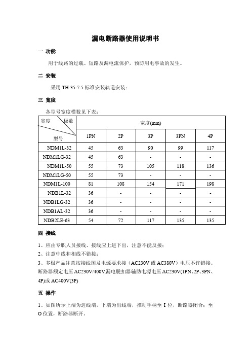
各型号宽度模数见下表: 宽度 极数
宽度(mm)
型号
1PN
2P
3P
3PN
4P
NDM1L-32
45
63
90
99
117
NDM1LG-32
45
63
-
-
-
NDM1L-50
中文Socomec Resys M40

否 否 否 是 否 否
• •
预 报 警功能 当故障电流超过动作值的 50%,预报警输出触点动作(若选)。当故障电流下降至预设值的 30%,该触点将自动 复位。 使用 DIP 开关 A 与 B 来选择继电器的动作方式。当选择正向安全,继电器通常处于励磁(闭合)状态,当发生故 障时处于失磁(打开)状态。当选择负向安全,继电器通常处于失磁(打开)状态,当发生故障时处于励磁(闭 合)状态。
The information provided in this literature is believed to be accurate (subject to change without prior notice); however, use of such information shall be 50m* m ax. entirely at the user’s own risk.
PDF 文件使用 "pdfFactory Pro" 试用版本创建
L1 L2 L3 N E
• 安装详图
30mm 44mm 49.5mm 63.5mm
1
2
3
4
5
6
7
*Dual voltage only available 只在 115V/230V AC 是作为 as 115V/230V AC. For 115V, connect across 双电源。 terminals 6 and 7 使用 115V 时连接端子 6 和 7。 For all other voltages, 使用其他电压等级电源时连接 connect across terminals 5 and 端子 5 和 7。 7.
标准:
A B C D
•
电源保护器操作手册说明书

Contentseg a Pn o i t p i r c s e D Introduction ..............................2Ins tallation ..............................3Manual Operatio n .........................4Inspection and Field Che cks .. (6)Installation Instructions for Series C F-FrameMotor Circuit Protector Type HMCP & HMCPS.............Installation Instructions for Series CF-Frame Instruction Leaflet IL 29C401KMotor Circuit Protector Type HMCP & HMCPSE ective December 20132EATON CORPORATION 3Instruction Leaflet IL 29C401KInstallation Instructions for Series C F-Frame Motor Circuit Protector T ype HMCP & HMCPSEATON CORPORATION E ective December 20134Instruction Leaflet IL 29C401KE ective December 2013Installation Instructions for Series CF-FrameMotor Circuit Protector Type HMCP & HMCPSEATON CORPORATION 5Instruction Leaflet IL 29C401KInstallation Instructions for Series C F-Frame Motor Circuit Protector T ype HMCP & HMCPSEATON CORPORATION E ective December 2013Instruction Leaflet IL 29C401K E ective December 2013Installation Instruction for Series CF- Frame Motor Circuit Protector Type HMCP & HMCPSEATON CORPORATION 67Instruction Leaflet IL 29C401KInstallation Instructions for Series C F-Frame Motor Circuit Protector T ype HMCP & HMCPSEATON CORPORATION E ective December 2013Instruction Leaflet IL 29C401K Installation Instructions for Series C F-FrameMotor Circuit Protector T ype HMCP & HMCPSEaton CorporationElectrical Group1000 Cherrington ParkwayMoon Township, PA 15108United States877-ETN-CARE (877-386-2273)© 2013 Eaton CorporationAll Rights ReservedPrinted in Dominican Republic Publication No. IL 29C401K/ TBG000464 Part No. 6620C47H10December 2013Eaton is a registred trademark of Eaton Corporation.All other trademarks are property of their respective owners.The instructions for installation, testing, maintenance, or repair herein are provided for the use of the product in general commercial applications and may not be appropriate for use in nuclear applica-tions. Additional instructions may be available upon request to replace, amend, or supplement these instructions to qualify them for use with the product in safety-related applications in a nuclear facility.The information, recommendations, descriptions, and safety nota-tions in this document are based on Eaton’s experience and judg-ment with respect to R tting of Power Breakers. This instruction-al literature is published solely for information purposes and should not be considered all-inclusive. If further information is required, you should consult an authorized Eaton sales representative.The sale of the product shown in this literature is subject to the terms and conditions outlined in appropriate Eaton selling policies or other contractual agreement between the parties. This literature is not intended to and does not enlarge or add to any such contract. The sole source governing the rights and remedies of any purchaser of this equipment is the contract between the purchaser and Eaton. NO WARRANTIES, EXPRESSED OR IMPLIED, INCLUDING WARRANTIES OF FITNESS FOR A PARTICULAR PURPOSE OR MERCHANTABILITY, OR WARRANTIES ARISING FROM COURSEOF DEALING OR USAGE OF T RADE, ARE MADE REGARDINGTHE INFORMATION, RECOMMENDATIONS, AND DESCRIPTIONS CONTAINED HEREIN. In no event will Eaton be responsible to the purchaser or user in contract, in tort (including negligence), strict liability or otherwise for any special, indirect, incidental or conse-quential damage or loss whatsoever, including but not limited to damage or loss of use of equipment, plant or power system, costof capital, loss of power, additional expenses in the use of existing power facilities, or claims against the purchaser or user by its cus-tomers resulting from the use of the information, recommendations and description contained herein.。
M-System MD-INSP 电信ISDN电路用 lightning 闪电保护器说明书

BEFORE USE ....Thank you for choosing M-System. Before use, check the package you received as below .If you have any problems or questions on the product, please contact M-System’s Sales Office or representatives.n PACKAGE INCLUDES:Lightning surge protector (body + base socket) .........(1)n MODEL NO.Confirm that the model number described on the product is exactly what you ordered.n INSTALLATION / INSTRUCTION MANUALThis manual describes necessary points of caution when you use this product, installation, and basic maintenance procedure.LIMITATION APPLICABLE TO M-RESTERThe M-Rester will protect electronics equipment from damage caused by lightning by absorbing most of the surge voltages.However, M-Rester may not be effective against certain extremely high voltages caused by a direct or almost direct hit by lightning.M-Rester must be installed according to this installation / instruction manual.POINTS OF CAUTIONn GENERAL• Before you remove the body from its base socket or mount it, or connect/disconnect leadwires to the M-RESTER,turn off the input signal to the M-RESTER and power supply for peripheral devices for safety .• DO NOT DO any maintenance work for the M-RESTER during thunder storms.n ENVIRONMENT• When heavy dust or metal particles are present in the at-mosphere, install M-RESTER inside proper housing and ventilate it.• Do not install the M-RESTER where it is subjected to continuous vibration. Do not apply physical impact to the M-RESTER.• Environmental temperature must be within -5 to +55°C (23 to 131°F) and relative humidity within 30 to 90% RH in order to ensure adequate life span and operation.• Altitude up to 2000 metersn INSULATION TEST• The maximum applicable voltage for testing insulation between ISDN circuit and the housing is 250V DC. If a greater voltage is applied, the element will start dis-charging at discharge voltage, which can cause insula-tion failure or loss of dielectric strength.If a greater voltage must be applied, remove the element body from the base socket, close across its terminals 5–3 and 6 – 4, before conducting a test.Be sure to open these terminals again and return the body after the test.n AND ....• We recommend that you keep spare M-RESTERs so that you can replace them when necessary .• Lightning surge can enter not only through signal lines but also through power supply lines. We recommend that you also use the Lightning Arrester for Power Lines for sufficient protection.GENERALn FUNCTION & FEATURES•Designed specifically for ISDN circuit n SPECIFICATIONSBETWEEN LINES LINE TO GNDDischarge voltage ±65V min ±290V min.Max. surge voltage * ±100V max. ±650V max.Leakage current ≤50µA ≤50µA @±65V DC@±140V DCMaximum line voltage ±65V Response time ≤0.1 µsec.Discharge current 500A for modular jack connection(8 / 20 µsec.)10000A for screw terminal connectionMaximum load current 100mAInternal series resist.approx. 4Ω including return*The maximum voltage that could pass through M-RESTER.Protected equipment must be able to withstand this voltage for a very short time period.COMPONENT IDENTIFICATION056 222 38 18SEN TRONIC AGn FRONT PANEL CONFIGURATIONNSTALLATIONPull out the body in pressing the clamps located at the top and bottom of the unit for separating it from the base socket. n DIN RAIL MOUNTINGSet the base socket so that its DIN rail adapter is at the bottom. Hung the upper hook at the rear side of base socket on the DIN rail and push in the lower. When removing the socket, push down the DIN rail adapter utilizing screwdriver (–) and pull.n WALL MOUNTINGRefer to the drawings in the figure below.EXTERNAL DIMENSIONS mm [inch]•When mounting, no extra space is needed between units.TERMINAL CONNECTIONSConnect the unit as in the diagram below .Be sure to cross-wire between Ground terminal of the protected equipment and one of the ground terminals (G) of the MD-INS. When the protected device has no ground terminal such in the case of M-System products, ground only the one of the MD-INS.The MD-INS can be connected to ISDN circuit via modular jack ports or screw terminals. We recommend, however, to use the screw terminals because the MD-INS is capable of a discharge current up to 10000A (8/20 µsec.) when it is connected via these terminals, while it is up to 500A (8/20 µsec.) with modular jacks.There is no difference in discharge current capacity at the DSU side by either means.n MODULAR JACK COVERSBe sure to put modular jack covers when they are not used. n SCHEMATIC CIRCUITRYGROUND TERMINALS (G)LINE ISDN SIDE DSU SIDEISDN CIRCUITBe sure to cross-wire between the G terminal of telephone set and one of the terminals 7, 8, 1, or 2 of the MD-INS.nCONNECTION DIAGRAMn GROUNDINGA crossover wire between M-RESTER ground and ground or metallic housing of equipment is required for protection.If the protected equipment has no ground terminal, ground the M-RESTER only.MAINTENANCECheck M-RESTER periodically. Many cases of lightning are ignored, and even lightning at a far distance often causes inductive surges.We recommend that you check your M-RESTER about twice a year, before and after the rainy season. Check whenever you experience a strong lightning occurrence.Checking procedure is explained in the following:n CHECKINGWIRING• Make sure that the wires are connected as instructed in the connection diagram.• Make sure that Ground terminal (G) is connected to the metallic housing of protected equipment.• Make sure that Ground terminal (G) is grounded to earth. ELEMENT MODULERemove all wiring connected to M-RESTER when you test the discharge elements.• Check resistance across the following terminals on the high resistance range of multimeter and confirm no con-duction. (The meter will indicate the same value as it will show when these terminals are open.)Terminals (5) – (6), (5) – (7), (6) – (7)• Check that discharging occurs across the same terminals with a 500V DC/1000MΩ megger. (The megger will show 20MΩ or less.)• If any of the above tests shows negative, replace the M-RESTER.。
P40M 电动机保护装置 使用说明书

P40M系列电动机保护装置使用说明书(V1.5)河南森尼瑞电气有限公司目录1装置简介 (1)2技术指标 (3)3保护功能及原理 (5)4保护信息说明 (14)5测控功能 (18)6人机接口说明 (19)7背板端子和接线原理图 (22)8机箱结构 (27)9装置选型 (28)10投运说明及注意事项 (28)11贮存及保修 (29)注:本资料版权为河南森尼瑞电气有限公司所有,受版权法的保护,使用仅限于森尼瑞电气的用户,未经本公司书面许可,不得以任何形式和方式提供给第三者,同时本公司保留对资料的修改和解释权。
1装置简介P40M系列微机电动机保护装置适用于3kV~10kV电压等级的中高压异步电动机的保护及测控,既可以直接安装在开关柜上,也可组屏安装。
其中P41M微机电动机保护用于2000kW 以下中小型异步电动机的保护;P42M微机电动机保护用于2000kW及以上大型异步电动机的保护。
1.1功能配置1.2装置主要特点●加强型单元机箱按抗强振动、强干扰设计,特别适应于恶劣环境,可分散安装于开关柜上运行。
集成电路全部采用工业品或军品,使得装置有很高的稳定性和可靠性。
●采用32位ARM作为CPU,采用实时多任务嵌入式操作系统。
保护功能不依赖通讯网,网络瘫痪与否不影响保护的正常运行。
●采用大屏幕汉字液晶显示,能显示多种测量参数,能查看运行状态,能显示或修改保护定值。
人机界面友好,信息详细直观,操作、调试方便。
●大容量的信息记录。
可保存不小于1000个最近发生的动作报告、事件记录、复位报告、开机时间、关机时间、掉电时间等,便于事故分析。
●具备录波功能。
装置记录保护动作前后25个周波(每周波64点)的采样数据,能就地液晶界面显示,保护跳闸后上送配电自动化系统主站,也可以通过故障分析软件进行故障分析。
●有独立测量CT,具有“综合保护”和“测量仪表”功能,带31次谐波测量,一个装置具有两种功能,为用户节省成本。
●完善的软硬件自检功能。
S40综合保护器

施耐德SEPAM 20/40系列微机保护装置使用说明手册面板操作说明S e pa m 前面板由状态指示灯(LE D ),液晶显示屏(LC D ),操作按钮和诊断整定专用R S 232连接口组成,如下图所示:液晶显示屏(LC D ) 为5行显示,尺寸为60m m X 43m m 。
它是一种图形化的液晶显示,可显示数字、中/英文信息和各种图形符号,用于显示测量值,保护/参数整定值以及报警和运行信息。
操作语言将可以根据设定显示为中文或英文,因此非常方便中国用户操作和使用。
状态指示灯为LE D 发光二极管,其中”o n ”表示为工作电源状态(有电源时为绿色);扳手指示灯表示为继电器内部故障(当发生继电器故障时为闪烁的红色,),后面的9个指示灯为主回路运行状态指示灯,标准设置时I>表示为相过流,I>>表示为相速断过流,I 0> 表示为零序过流,I 0>>表示零序速断过流,ex t 表示外部跳闸,另有一个指示灯可由用户定义为其他功能指示,0 o ff 为开关分闸状态,1 on 为开关合闸状态,Tri p 为故障跳闸指示。
这9个指示灯也可根据用户的情况使用调试整定软件S F T2841进行重新定义,然后由S F T2841软件根据重新定义的含义打印出相应的文字信息,并且可将打印的信息重新粘贴到S e pa m 面板指示灯上方从而指示新的含义。
操作按钮为触摸式图标化按键,共有9个按键。
根据使用功能的不同,这9个按键被分成白色、兰色和兰/白色三种颜色。
如下图所示:状态指示灯 操作按钮 液晶显示屏 调试整定专用RS232连接口白色按键:①为测量键,用于显示测量值②为诊断键和其他测量键,用于显示开关设备及网络诊断数据③为报警信息键,用于显示报警信息兰色/白色按键:为④⑤⑥三个键,具有双重功能。
当用为白色按键功能时为:④复位键,用于继电器复位功能⑤清除键,用于报警的确认和清除⑥灯测试键,用于对面板上的所有指示灯和液晶显示屏的测试当用为兰色按键功能时为:④确认键,用于参数和保护整定时的数据确认⑤向上光标键,用于参数和保护整定时向上移动光标或数字⑥向下光标键,用于参数和保护整定时向下移动光标或数字兰色按键:⑦为保护整定键,用于存取保护整定值⑧为S e p am参数整定键,用于存取S e p am通用参数整定值⑨为密码键,用于输入确认密码以进行有效的保护和参数整定对于正常的面板按钮操作可分为测量值和参数的读取以及进行保护和参数整定。
爱斯顿MPNC404YEAXX2A 型号的爱斯顿Magnum低压电源电路保护器说明书
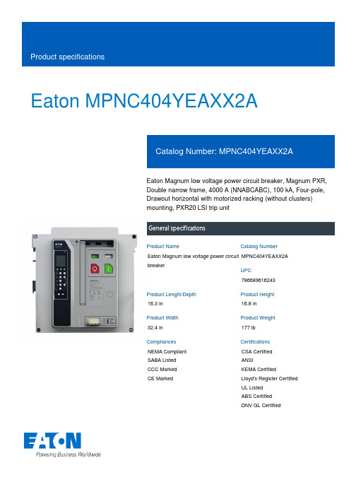
Eaton MPNC404YEAXX2AEaton Magnum low voltage power circuit breaker, Magnum PXR,Double narrow frame, 4000 A (NNABCABC), 100 kA, Four-pole,Drawout horizontal with motorized racking (without clusters)mounting, PXR20 LSI trip unitGeneral specificationsEaton Magnum low voltage power circuitbreakerMPNC404YEAXX2A78668961624316.3 in16.8 in32.4 in177 lbNEMA Compliant SABA Listed CCC MarkedCE Marked CSA CertifiedANSIKEMA CertifiedLloyd's Register Certified UL ListedABS CertifiedDNV GL CertifiedProduct Name Catalog NumberUPCProduct Length/Depth Product Height Product Width Product Weight Compliances CertificationsApplication notesZone selective interlocking application paperBrochuresMagnum circuit breakers with Power Xpert Release trip units product aidCatalogsSelevctive coordination application paper - IA0120000E3Certification reportsMagnum PXR and PD-SB double and double narrow frame UL Certificate of ComplianceMagnum PXR and PD-SB standard and narrow frame UL Certificate of ComplianceManuals and user guidesMicrosoft Word - Power Xpert Protection Manager Quick StartGuide.docxMagnum PXR low voltage power circuit breakers user manualPower Xpert Release trip unit for Magnum PXR circuit breakers PXR20/25 user manualSoftware, firmware, and applicationsPower Xpert Protection Manager x32 22.06 1Power Xpert Protection Manager x64 22.6 1Specifications and datasheetsEaton Specification Sheet - MPNC404YEAXX2ALow voltage circuit breakers guide specTime/current curvesMagnum PXR 20/25 electronic trip units time current curvesWhite papersCyber security white paperSafer by design: arc energy reduction techniquesMolded case and low-voltage power circuit breaker healthEaton Corporation plc Eaton House30 Pembroke Road Dublin 4, Ireland © 2023 Eaton. All Rights Reserved. Eaton is a registered trademark.All other trademarks areproperty of their respectiveowners./socialmedia。
德力西 DZ47sLES小型漏电保护断路器使用说明书
DZ47sLES RESIDUAL CURRENT OPERATEDCIRCUIT-BREAKER NAVIGATORSeries User ManualPlease carefully read this User Manual before installing and operating the product, and keep this manual properly for futurereferenceSafety NoticePlease carefully read this manual before the installation, operation, run, maintenance, and inspection of the product, and install and operate this product properly according to the contents of the instructions.Danger:⚫It is prohibited to operate the circuit breaker with your wet hands;⚫It is prohibited to touch the conductive part during operation;⚫Make sure that the product is de-electrified during the maintenance and service;⚫It is prohibited to use the short circuit method to test the product;Caution:⚫The installation, maintenance, and service shall be carried out by the qualified professionals;⚫All characteristics of the product have been set in the factory, and the product cannot be disassembled without permission or adjusted at will during operation;⚫Please confirm that the product voltage, rated current, frequency, and characteristics of the product meet the working requirements before use;⚫Connect the wire according to the wiring mark on the product (the load end is the outlet terminal); tighten the wiring screw when the wire is inserted into the wiring hole, and fasten the wire until it cannot be loose or pulled out; the exposed copper wire head shall not be exposed outside the terminal block;⚫This product cannot provide the protection for electric shock caused by contact with two wires of the protected circuit simultaneously;⚫This product has an IP20 protection level without dustproof protection. Therefore, when used in a dusty place, it shall be installed in a well-sealed terminal box;⚫When there is voltage on the power supply side, the circuit board of the product is in the working state after power-on and here is a certain temperature on the side, and this belongs to the normal phenomenon;⚫This product is not suitable for some special applications such as frequent motor starting, electric heating equipment, capacitor cabinets, high inductive and high capacitive loads and high temperature environments;⚫If found damage or heard abnormal sound when unpacking the product, please stop the operation immediately and contact the supplier;Table of Contents1 Main Purpose and Scope of Application…………………………............................................................................2 Product Model and Its Meanings (1)2.1 Product Model and Its Meanings................................................................... .. (1)2.2 Panel Introduction (2)3 Normal Working Conditions and Installation Conditions (2)4 Technical Characteristics................................................................... (3)4.1 Classification (3)4.2 Main Technical Parameters (3)4.3 Main Technical Performances (4)5 Outline and Installation Dimensions (4)6 Installation, Operation and Maintenance............................................. .. (5)7 Troubleshooting............................................. . (6)8 Unpacking Inspection............................................. . (7)9 Company’s commitments............................................. . (7)1 Main Purpose and Scope of ApplicationDZ47sLES series residual current operated circuit breaker (hereinafter referred to as leakage circuit breaker) has electric leakage (electric shock), overload, and short circuit protection functions, and can also have over-voltage and under-voltage protection functions according to the needs of users.DZ47sLES leakage circuit breaker is used in the AC 50/60Hz lines with rated voltage 230V/400V and rated current up to 63A for indirect contact protection of people, as well as overcurrent protection for buildings and similar lines. It can also provide protection against fires caused by persistent earth faults due to the non-operation of the overcurrent protection device. Leakage circuit breakers with overvoltage protection can also provide the production against excessive voltage increases due to grid faults.This series of products has been increasingly used in low-voltage power distribution systems as a backup protection against earth faults, direct contact and indirect contact electric shocks.The circuit breaker is equipped with 6 different accessories, including: OF auxiliary contact, MX+OF shunt releases, SD alarm contact, MV overvoltage release, MN undervoltage release and MVMN overvoltage and undervoltage release. When there are multiple accessories installed, the size for maximum number of installations is less than 54mm.2 Product Model and Its Meanings2.1 Product Model and Its MeaningsAccessory code: By default: Common type; G: Overvoltage typeDerived code: Electronic leakage circuit breakerProduct series numberDesign No.Product code2.2 Panel IntroductionPress beforepower-onPress once a monthLoad endLegends:1 Inlet terminal2 Company Logo3 Product model (overvoltage model DZ47sLES G)4 Trip curve and rated current (see Table 1)5 Rated voltage (see Table 1)6 Breaking capacity and frequency (see Table 1)7 Reference standards8 Certification marks9 Identification on load end 10 N-pole marking 11 Reset button12. Rated residual making and breaking capacity, rated residual operating current, rated operating time, (overvoltage protection parameter is Uvo= (280±5%)V)13 Wiring diagram 14 Test button 15 Outline terminal3 Normal Working Conditions and Installation Conditionsa) Ambient air temperature:The upper limit of the ambient air temperature does not exceed +70°C, the lower limit does not below -35°C, and the mean temperature does not exceed +35°C within 24 hours; note: If the residual current operated circuit breaker is used in places where the ambient air temperature is higher than +70°C or below -35°C, please contact the manufacturer;b) AltitudeThe altitude of the installation site does not exceed 2000m;c) Atmospheric conditions:When the temperature is +60°C, the relative humidity of the air does not exceed 50%; a higher relative humidity is allowed at lower temperatures; for example, when the temperature is +20°C, the relative humidity does not exceed 90%. Special protection measures should be taken for condensation occurred occasionally due to temperature changes;d) Installation conditions:The external magnetic field near the installation site of the residual current operated circuit breaker should not exceed 5 times of the geomagnetic magnetic field in any direction; the installation position should be vertical, and the inclination angle in any direction should not exceed 10°; the product is installed in a place where there is no shock vibration and no rain or snow erosion; the standard TH35-7.5 steel installation rails are used for installation;e)Pollution degree: Level 2;f)Installation category: Class II, Class III;g)Protection grade: IP20 (Installed a power distribution tank, distribution cabinet or box: IP40);h)For product with a N pole, please connect the zero line to the pole marked with N when wiring.i)Normal storage and transport conditionsa)Temperature: -40°C~ +85°C;b)Relative humidity (at 25°C): ≤95%;c)Please handle the product gently during transportation, do not upside it down, and avoid strong collisions.4 Technical Characteristics4.1 Classificationa) According to the type of trip: Type B, type C, type D;b) According to the number of poles of the product: 1P+N, 2P (with and overcurrent protection pole), 3P, 3P+N, 4P;c) According to the rated current: 6A, 10A, 16A, 20A, 25A, 32A, 40A, 50A, 63A;d) According to the characteristics of leakage action: 10mA, 30mA, 50mA, 75mA, 100mA, 300mA.4.2 Main Technical Parameters4.3 Main Technical Performancea) Overcurrent release protection characteristics see Table 2b) Mechanical and electrical life1. Mechanical life: 20,000 times;2. Electrical life: 10,000 times.c) The protection characteristic curves of the circuit breaker are illustrated in Fig. 1.Fig. 1 B type thermal / electromagnetic trip characteristicscurveFig. 2 C type thermal /electromagnetic trip characteristicscurveFig. 3 D type thermal /electromagnetic trip characteristicscurve5 Outline and Installation DimensionsThe outline and installation dimensions are illustrated in Fig. 1.Fig. 1 Outline and installation dimensions6 Installation, Operation and Maintenancea)Check whether the product mark is consistent with the conditions used before installation;b)Correctly connect the wires at the inlet terminal and outlet terminal according to the product identification (the load current should be less than the rated current of the product);c)The N pole shall be connected correctly, and must be reliably wired, otherwise the product will not work normally;d)When installation, insert the residual current operated circuit breaker into the mounting rail until the residual current operated circuit breaker is fixed on it without looseness and fall-off. To dismantle the residual current operated circuit breaker, pull out the stopper.e)The rated tightening torque is 2.0N.m;f)The cross-sectional area of the connecting wire sees Table 3;Table 3 Sectional-area and rated current of the connecting (copper) wireRated current A 6 10 16, 20 25 32 40, 50 63Sectional area of wire mm 2 1 1.5 2.5 4 6 1016g) After power-on, operate the residual current operated circuit breaker test button several times and confirm whether it works reliably;h) The working reference temperature of the residual current operated circuit breaker is +30+50℃. When the ambient temperature changes, its rated value shall be corrected, and the temperature correction coefficient is listed in Table 4; if multiple residual current operated circuit breakers are installed in the same closed box, the temperature in the box will be increased accordingly, and the rated current should be multiplied by derating coefficient 0.8.7 Table 4 Rated current temperature correction coefficient tableTemp.Rated current (A)j) MaintenanceAfter the residual current operated circuit breaker is running for some time, it shall be checked regularly (monthly). After the circuit breaker is powered on and energized, press the test button and check the residual current operated circuit breaker can work reliably. If failure to work normally, please replace it immediately and do not operate it continuously.7 TroubleshootingThe faults and troubleshooting of the residual current operated circuit breaker see Table 5.Table 5 Fault and troubleshootingFault Cause SolutionM i s -o p e r a t i o nMis-operation caused by zero line earthed at the load side of the residual current operated circuit breaker When the zero line on the load side of the residual current operated circuit breaker is earthed, the normal operating current will flow in through the earth point to cause mis-operation.Residual current operated circuit breakerIncorrect wiringConnect the earth wire to the zero line at the power side of the residual currentoperated circuit breakerResidual current operated circuit breakerCorrect wiring Mis-operation bythe leakage current and the current ofthe wire tocapacitorWire on the load side is laid tightly on theground too longSelect the residual current operated circuit breaker with a large residual operating current The leakage current of the wire on the loadside to earth is increased due to insulationreduction.Replace wire8 Unpacking InspectionAfter unpacking, the user must check whether the product is intact, whether the exposed metal is rusty, and whether the product is defects due to poor transportation or storage. If found the above phenomenon, please stop the product, and contact the supplier timely for solution.9 Company’ commitmentThe free repair or replacement will be provided by the company for damage or abnormal operation of the product produced by our company due to poor manufacturing quality within 36 months from the date of the production under the premise that the user conforms to the operation and storage conditions and that the product is well sealed.A paid repair is provided when the warranty period expires. However, the paid repair is provided for damage caused by one of the following situations even within the warranty period:a)Improper operation, maintenance, or storage;b)Modification without permission, or improper maintenance;c)Damage caused by falling off after purchase or occurred during the installation process;d)Irresistible nature disasters such as earthquakes, fires, lightning strikes, and abnormal voltages.If you have any questions, please contact the dealer or the company’s customer service department.Customer service hotline: 400-826-8008Page 7CertificateDELIXI ELECTRIC LTDDELIXI ELECTRIC LTDDelixi Industrial Park, Liushi Town, Yueqing City, Zhejiang Province P/C.: 325604 Tel: (86-577)6177 8888Fax: (86-577)6177 8000Customer service hotline: 400-826-8008The first edition of this User Manual was issued in Nov. 2021.。
德力西 DZ47sLES小型漏电保护断路器 说明书

安装、使用产品前,请仔细阅读使用说明书并妥善保管、备用安全告知在安装、操作、运行、维护、检查之前,请务必认真阅读本说明书,并按照说明书上的内容准确安装、使用本产品。
危险:严禁湿手操作断路器; 使用中,严禁触摸导电部位;维护与保养时,必须确保产品不带电; 严禁用短路的办法来测试产品。
注意:安装、维护与保养时,应由具有专业资格的人员操作;产品的各项特性出厂时已整定,使用中不能自行拆装或随意调节; 使用前请确认产品工作电压、额定电流、频率及特性是否符合工作要求; 按照产品上的接线标识进行安装接线(负载端即出线端);导线伸入接线孔后拧紧接线螺钉,拧紧导线使导线不得松动、拔出,裸露铜线头不能露在接线端外; 本产品对同时接触被保护电路两线引起的触电危险不能进行保护;本产品防护等级IP20不具备防尘功能,当用于灰尘较多的场合时,请安装于密封较好的终端箱中;本产品不适用于电动机频繁启动、电热设备、电容柜、高感性、高容性负载和高温环境等特殊场合;如果产品在开箱时有破损或异常响声,应立即停止使用并联系供应商。
电源侧有电压时,合闸后产品中线路板处在工作状态,侧面有一定温度,属于正常现象;目录1主要用途及适用范围 ....................................................... 错误!未定义书签。
2产品型号及含义 . (1)2.1产品型号及含义 (1)2.2面板介绍 (2)3 正常工作条件和安装条件 (2)4技术特性 (3)4.1 分类 (3)4.2 主要技术参数 (3)4.3 主要技术性能 (4)5外形及安装尺寸 (4)6安装、使用和维护 (5)7故障分析 (6)8 开箱检查 (7)9公司承诺 (7)1主要用途及适用范围DZ47sLES系列剩余电流动作断路器(以下简称漏电断路器)具有漏电(触电)、过载、短路等保护功能,还可根据用户的需要增加过压,欠压保护功能。
DZ47sLES漏电断路器适用于交流50/60Hz,额定电压230V/400V,额定电流至63A及以下的线路中,用来对人的间接接触保护,以及对建筑物及类似用途的线路进行过电流保护。
漏电断路器使用说明书

1、因私自拆开产品而引起的质量问题,责任自负; 2、对同时接触的被保护线路的两相而引起的触电,不能进行保护; 3、请勿直接或间接在产品上用兆欧表或类似设备测试产品的绝缘电阻或进行工 频耐压试验,以免对产品造成损坏。如用户需要,本公司可提供此项合格试验的 有效证明; 4、工程线路进行线路的绝缘电阻测试时,不能连接产品,以免对产品质量造成 误解或对产品线路板造成损坏。 5、漏电断路器接线为上进下出,请勿接反,否则再按检测按钮或线路中出现漏 电流的情况下会损坏产品。 6、接线可靠,防止因接线端出现异常热引起漏电断路器勿动或造成接线端烧损。 7、每月进行一次漏电模拟测试,即按试验按钮使断路器动作,以检测断路器是 否正常工作,对工作异常的产品及时更换。 8、若漏电断路器自动断开,应及时分析线路或设备故障原因,排除故障后方可 通电。
五 操作
1、如图所示上端为进线端,下端为出线端,推动手柄至 I 位,断路器闭合;至 O 位置,断路器断开。
2、若因漏电自动断开时,NDM1L 系列漏电指示凸起(再闭合时须按下漏电指 示)NDB1L、NDB1AL-32 系列漏电指示显示红色;无指示的断开为过载、短路 自动断开或手动断开。 3、按试验按钮 T 模拟漏电动作,漏电断路器应自动断开,漏电指示正常。安装 完漏电断路器,应按试验按钮测试 3 次,均应正常动作;以后每月测试一次,如 不能正常动作,则须更换产品。
36
-
-
-
-
NDB2LE-63
54
72
117
135
135
四 接线
1、应由专职人员接线、接线应上进下出,注意不能反接; 2、注意中线和相线不错接; 3、多极产品注意按接线图及电源要求接(AC230V 或 AC380V)电压不许错接。 断路器额定电压 AC230V/400V,漏电脱扣器辅助电源电压 AC230V(1PN、2P、3PN、 4P)或 AC400V(3P)
产品使用说明书(GRZL智能漏电断路器)
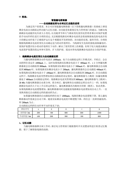
O 附录:智能漏电断路器——自动跟踪定档与合闸记忆功能的说明为满足用户的要求,本公司在智能漏电断路器(以下简称漏电断路器)的基础上增设剩余电流自动跟踪定档功能与记忆功能。
该功能是依据基层电力管理部门的建议,为解决线路剩余电流随用电负荷大小变化,以及随季节和天气晴雨变化使用电管理者难以对保护装置的手动动作档位进行合理的设定,无法根据线路实时剩余电流状态使故障接地危险电流在较小的额定动作值下正确保护运行这个难题而开发研制的。
该功能的实现,能科学的、合理的根据线路剩余电流的变化自动确定适当的动作值档位,当线路发生危险的接地故障漏电时,使保护装置在较小的动作值档位下动作,解决了使用管理上的难题,有利于较大地提高剩余电流保护装置的投运率和可靠性,扩大保护面,提高对供电线路剩余电流的安全保护性能。
1、线路剩余电流的变化与自动跟踪定档当漏电断路器剩余动作电流在1000mA,处于自动跟踪定档工作模式时,开机后,会自动把档位设定在1000mA上。
这时如果线路实际剩余电流小于400mA时,1-2分钟漏电断路器就会自动跟踪到800mA,如果线路实际剩余电流小于300mA时,漏电断路器会自动跟踪到600mA时,如果线路实际剩余电流小于200mA。
漏电断路器再会自动跟踪400mA时,如果线路实际剩余电流小于100mA时,漏电断路器再会自动跟踪到200mA时。
在自动跟踪定档下,线路剩余电流突然增加到自动跟踪的设定值时,漏电断路器马上跳闸(如漏电断路器处于600mA自动跟踪定档时,线路剩余电流突然增加到600mA,漏电断路器马上跳闸),20-60s内漏电断路器自动重合闸,重合闸后,漏电断将自动跟踪定档自动升上一档,如果线路剩余电流仍大于比上升后的定档值大,漏电断路器再次跳闸并闭锁(跳死),依此类推。
如果线路剩余电流缓慢增加,漏电断路器同时也能随着线路剩余电流增加而自动上升,一直变换到接近自动跟踪定档的最高档为止。
如果漏电断路器的自动跟踪档档位处于1000mA,线路的剩余电流缓慢下降,那么漏电断路器动作值就会自动下降,随着实际剩余电流的不断缓慢下降,档位会一直降到最低档,即200mA为止。
