三层交换链路聚合实验文档
补充三层交换机配置DHCP服务与交换机间链路聚合配置

补充实验三层交换机配置DHCP服务与交换机间链路聚合配置【实验目的】1、三层交换机配置DHCP功能,实现分别为不同VLAN自动分配IP地址等相关参数2、掌握在两台交换机之间配置链路聚合,实现将低速链路捆绑为高速链路【实验拓扑】【实验步骤】1、三层交换机配置//分别创建VLAN 10与VLAN 20Switch#conf tSwitch(config)#hostname MSMS(config)#vlan 10MS(config-vlan)#vlan 20//配置VLAN 10与VLAN 20虚拟接口的IP地址MS(config)#int vlan 10MS(config-if)#ip address 192.168.1.254 255.255.255.0MS(config-if)#no shutdownMS(config-if)#exitMS(config)#int VLAN 20MS(config-if)#ip address 192.168.101.254 255.255.255.0MS(config-if)#no shutdownMS(config-if)#exit//三层交换机配置DHCP服务//添加排除地址MS(config)#ip dhcp excluded-address 192.168.1.254MS(config)#ip dhcp excluded-address 192.168.101.254//创建VLAN10与VLAN20两个VLAN自动分配IP地址的地址池及网关IP MS(config)#ip dhcp pool vlan10pool //地址池名称为vlan10poolMS(dhcp-config)#network 192.168.1.0 255.255.255.0//配置VLAN 10虚拟接口IP作为DHCP客户端的网关IPMS(dhcp-config)#default-router 192.168.1.254MS(dhcp-config)#exitMS(config)#ip dhcp pool vlan20pool //地址池名称为vlan10poolMS(dhcp-config)#network 192.168.101.0 255.255.255.0MS(dhcp-config)#default-router 192.168.101.254//配置VLAN20虚拟接口IP作为DHCP客户端的网关IPMS(dhcp-config)#exit//三层交换机的F0/23与F0/24端口捆绑为聚合链路MS(config)#interface range f0/23-24MS(config-if-range)#channel-group 1 mode on //通道组1工作模式为on//在三层交换机上查看聚合端口MS(config-if)#endMS#show interface etherchannel//在三层交换机上查看链路聚合配置MS#show etherchannel summary//三层交换机聚合链路配置为交换机之间VLAN的Trunk链路MS(config)#int port-channel 1 //端口通道1MS(config-if)#switchport trunk encapsulation dot1q//配置Trunk链路封装格式为802.1qMS(config-if)#switchport mode trunk2、二层交换机配置//创建VLAN 10与VLAN 20Switch(config)#vlan 10Switch(config-vlan)#vlan 20Switch(config-vlan)#vlan 20Switch(config-vlan)#exit//划分F0/1端口属于VLAN 10,F0/2端口属于VLAN 20Switch(config)#int f0/1Switch(config-if)#switchport mode accessSwitch(config-if)#switchport access vlan 10Switch(config-if)#exitSwitch(config)#int f0/2Switch(config-if)#switchport mode accessSwitch(config-if)#switchport access vlan 20Switch(config-if)#exitSwitch(config)#//二层交换机的F0/23与F0/24端口捆绑为聚合链路Switch(config)#int range f0/23-24Switch(config-if-range)#channel-group 1 mode on//通道组1工作模式为on //在二层交换机上查看聚合端口Switch#show interface etherchannel//在二层交换机上查看链路聚合配置Switch#show etherchannel summary//二层交换机聚合链路配置为交换机之间VLAN的Trunk链路Switch(config)#int port-channel 1 //端口通道1Switch(config-if)#switchport mode trunk3、两台PC配置为DHCP客户端,实现自动从三层交换机(DHCP服务)获取IP地址、子网掩码及网关IP此时两PC机之间相互无法访问(属于不同VLAN)若要实现不同VLAN的主机间能够相互访问,必须在三层交换机配置路由功能即可。
华为三层交换综合(VRRP-OSPF-STP-SNMP链路聚合)案例--主交换配置

port trunk permit vlan all
lacp enable
#
interface GigabitEthernet1/0/44
duplex full
speed 1000
port link-type trunk
port trunk permit vlan all
华为三层交换综合(VRRP-OSPF-STP-SNMP链路聚合)案例--主交换配置
来源: 作者: 发布时间:2008-05-26 阅读次数710
亚威CISCO培训六月暑期优惠——史上最低价
dis ver
Copyright Notice:
All rights reserved (Sep 10 2005).
description HeXin Database
ip address 10.34.16.253 255.255.255.0
vrrp vrid 1 virtual-ip 10.34.16.254
vrrp vrid 1 priority 110
#
interface Vlan-interface102
#
interface GigabitEthernet1/0/32
port access vlan 104
#
interface GigabitEthernet1/0/33
port access vlan 104
#
interface GigabitEthernet1/0/34
port access vlan 104
#
vfs check check-method fix
Cisco交换机链路聚合

实用标准文案下面是局域网的核心交换机(三层交换)和二层交换之间的端口聚合的操作实例:2950Switch>enSwitch#conf tEnter configuration commands, one per line. End with CNTL/Z.Switch(config)#int f0/1Switch(config-if)#channel-group 1 mode on%LINK-5-CHANGED: Interface Port-channel 1, changed state to up%LINEPROTO-5-UPDOWN: Line protocol on Interface Port-channel1, changed state to upSwitch(config-if)#int f0/2Switch(config-if)#channel-group 1 mode on3560Switch(config)#int port-channel 1Switch(config-if)#exit精彩文档.实用标准文案Switch(config)#ip routing(默认已经启用了路由功能)Switch(config)#int port-channel 1Switch(config-if)#no switchportSwitch(config-if)#ip add 1.1.1.1 255.0.0.0Switch(config-if)#no shutSwitch(config-if)#exitSwitch(config)#int f0/1Switch(config-if)#no switchport%LINEPROTO-5-UPDOWN: Line protocol on Interface FastEthernet0/1, changed state to down%LINEPROTO-5-UPDOWN: Line protocol on Interface FastEthernet0/1, changed state to upSwitch(config-if)#Switch(config-if)#no ip addSwitch(config-if)#channel-group 1 mode ?active Enable LACP unconditionallyauto Enable PAgP only if a PAgP device is det ected 精彩文档.实用标准文案desirable Enable PAgP unconditionallyon Enable Etherchannel onlypassive Enable LACP only if a LACP device is detectedSwitch(config-if)#channel-group 1 mode on%LINK-5-CHANGED: Interface Port-channel 1, changed state to up%LINEPROTO-5-UPDOWN: Line protocol on Interface Port-channel1, changed state to upSwitch(config-if)#Switch(config-if)#int f0/2Switch(config-if)#no switchport%LINEPROTO-5-UPDOWN: Line protocol on Interface FastEthernet0/2, changed state to down%LINEPROTO-5-UPDOWN: Line protocol on Interface FastEthernet0/2, changed state to upSwitch(config-if)#no ip add精彩文档.实用标准文案Switch(config-if)#no ip addressSwitch(config-if)#channel-group 1 mode onSwitch(config-if)#exitSwitch(config)#int f0/3Switch(config-if)#no switchport%LINEPROTO-5-UPDOWN: Line protocol on Interface FastEthernet0/3, changed state to down%LINEPROTO-5-UPDOWN: Line protocol on Interface FastEthernet0/3, changed state to upSwitch(config-if)#ip add 2.2.2.1 255.0.0.0Switch(config-if)#no shut端口聚合可使流量在多条物理链路上负载均衡,同时也起到了链路的备份作用。
计算机网络交换三级网络综合实验

计算机⽹络交换三级⽹络综合实验交换三级⽹络综合实验(简化)【实验名称】交换三级⽹络综合实验【实验⽬的】了解交换三级⽹络架构掌握各层相关协议的配置⽅法。
【技术原理】三层架构:三层⽹络架构采⽤层次化模型设计,即将复杂的⽹络设计分成⼏个层次,每个层次着重于某些特定的功能,这样就能够使⼀个复杂的⼤问题变成许多简单的⼩问题。
三层⽹络架构设计的⽹络有三个层次:核⼼层(⽹络的⾼速交换主⼲)、汇聚层(提供基于策略的连接)、接⼊层(将⼯作站接⼊⽹络)。
核⼼层:核⼼层是⽹络的⾼速交换主⼲,对整个⽹络的连通起到⾄关重要的作⽤。
核⼼层应该具有如下⼏个特性:可靠性、⾼效性、冗余性、容错性、可管理性、适应性、低延时性等。
在核⼼层中,应该采⽤⾼带宽的千兆以上交换机。
因为核⼼层是⽹络的枢纽中⼼,重要性突出。
核⼼层设备采⽤双机冗余热备份是⾮常必要的,也可以使⽤负载均衡功能,来改善⽹络性能。
汇聚层:汇聚层是⽹络接⼊层和核⼼层的“中介”,就是在⼯作站接⼊核⼼层前先做汇聚,以减轻核⼼层设备的负荷。
汇聚层具有实施策略、安全、⼯作组接⼊、虚拟局域⽹(VLAN)之间的路由、源地址或⽬的地址过滤等多种功能。
在汇聚层中,应该采⽤⽀持三层交换技术和VLAN的交换机,以达到⽹络隔离和分段的⽬的。
接⼊层:接⼊层向本地⽹段提供⼯作站接⼊。
在接⼊层中,减少同⼀⽹段的⼯作站数量,能够向⼯作组提供⾼速带宽。
接⼊层可以选择不⽀持VLAN和三层交换技术的普通交换机。
端⼝聚合(Aggregate-port):⼜称链路聚合,是指两台交换机之间在物理上将多个端⼝连接起来,将多条链路聚合成⼀条逻辑链路,形成⼀个拥有较⼤宽带的端⼝,从⽽形成⼀条⼲路,增⼤链路带宽,可以实现均衡负载,并提供冗余链路。
⽣成树协议(spanning-tree):作⽤是在交换⽹络中提供冗余备份链路,并解决交换⽹络中的环路问题。
是利⽤SPA(⽣成树算法),在存在交换环路的⽹络中⽣成⼀个没有环路的树型⽹络,运⽤该算法将交换⽹络冗余的备份链路逻辑上断开,当主链路有问题时能⾃动切换到备份链路,保证数据的正常转发。
三层交换机链路聚合配置应用实例

Cisco三层交换机链路聚合配置应用实例Cisco三层交换机链路聚合配置应用实例Cisco三层交换机链路聚合配置应用实例的方法交换机连接拓扑图如下:步骤:一、两台三层交换机上创建vlan:Sw0#conf tSw0(configure)#vlan 10Sw0(configure-vlan)#exitSw0(configure)#vlan 11Sw0(configure-vlan)#exit二、在Sw0交换机上将端口fa0/1-2加入到vlan10中,端口fa0/3加入到vlan 11中Sw0(configure)#int range fa0/1-2Sw0(configure-if-range)#switchport access vlan 10Sw0(configure-if-range)#exitSw0(configure)#int fa0/3Sw0(configure-if)# switchport access vlan 11Sw0(configure)#exit三、在Sw1交换机上将fa0/1-2号端口加入到vlan 10中,将fa0/3号端口加到vlan 100中Sw1#conf tSw1(configure)#int range fa0/1-2Sw1(configure-if-range)#switchport access vlan 10Sw1(configure-if-range)#exitSw1(configure)#int fa0/3Sw1(configure-if)#switchport access vlan 100Sw1(configure-if)#exit四、在Sw0和Sw1交换机上为每个vlan 配置虚拟ip地址Sw0#conf tSw0(configure)#int vlan 10Sw0(configure-if-vlan)#ip address 192.168.10.253 255.255.255.0Sw0(configure-if-vlan)#no shutdownSw0(configure-if-vlan)#exitSw0(configure)#int vlan 11Sw0(configure-if-vlan)#ip addresss 192.168.11.254 255.255.255.0 Sw0(configure-if-vlan)#no shutdownSw0(configure-if-vlan)#exitSw1#conf tSw1(configure)#int vlan 10Sw1(configure-if-vlan)#ip address 192.168.10.254 255.255.255.0 Sw1(configure-if-vlan)#no shutdownSw1(configure-if-vlan)#exitSw1(configure)#int vlan 100Sw1(configure-if-vlan)#ip address 192.168.100.254 255.255.255.0 Sw1(configure-if-vlan)#no shutdownSw1(configure-if-vlan)#exit五、将Sw0和Sw1交换机相连的fa0/1-2口进行聚合Sw0#conf tSw0(configure)#int range fa0/1-2Sw0(configure-if-range)#channel-group 1 mode desirableSw0(configure-if-range)#exitSw1#conf tSw1(configure)#int range fa0/1-2Sw1(configure-if-range)#channel-gropu 1 mode desirableSw1(configure-if-range)#exit【可选做】// 六、在Sw0和Sw1交换机上将聚合端口设置为trunk口Sw0#conf tSw0(configure)#int port-channel 1Sw0(configure-if)#switchport mode trunkSw0(configure-if)#switchport trunk native vlan 10Sw0(configure-if)#exitSw1#conf tSw1(configure)#int port-channel 1Sw1(configure-if)#switchport mode trunkSw1(configure-if)#switchport trunk native vlan 10Sw1(configure-if)#exit//七、在Sw0和Sw1交换机上设置默认路由(当然你也可以设置能实现路由功能的协议)Sw0#conf tSw0(configure)#ip route 0.0.0.0 0.0.0.0 192.168.10.254Sw0(configure)#exitSw1#conf tSw1(configure)#ip route 0.0.0.0 0.0.0.0 192.168.10.253Sw1(configure)#exit八、测试在PC0客户端设置其ip地址为:192.168.11.1,子网掩码为:255.255.255.0,网关地址为:192.168.11.254在PC1客户端设置其ip地址:192.168.100.1,子网掩码为:255.255.255.0,网关地址为:192.168.100.254利用PC0客户端去ping PC1客户端的ip,检查是否能够ping 即可!!!*[注意]:在对Sw0和Sw1交换机上进行端口聚合后,如果没有设置聚合端口为trunk时,交换机两边是不能够被ping 通的。
实验一交换机链路聚合

实验一交换机链路聚合在计算机网络中,链路聚合是一种通过将多个物理链路绑定为一个逻辑链路来增加带宽和提高可靠性的技术。
本实验旨在探索交换机链路聚合的原理和应用。
一、实验目的通过实验,我们将了解以下内容:1. 交换机链路聚合的概念和原理;2. 配置和实现交换机链路聚合的方法;3. 测试和验证交换机链路聚合的效果。
二、实验设备和材料1. 交换机:至少两台支持链路聚合的交换机;2. 网线:用于连接交换机。
三、实验步骤1. 连接交换机将多台交换机通过网线相互连接,确保交换机之间可以正常通信。
2. 了解链路聚合的原理链路聚合技术能够将多个物理链路绑定为一个逻辑链路,提高带宽和可靠性。
链路聚合使用的是多路径传输技术,数据可以通过多个链路并行传输,提高数据传输效率。
3. 配置链路聚合根据交换机型号和操作系统的不同,链路聚合的配置方法可能有所不同。
一般而言,我们可以通过以下步骤进行配置:(1)登录到交换机的控制台;(2)找到链路聚合的配置选项;(3)选择要进行聚合的物理链路,并进行绑定和配置。
4. 实施链路聚合按照上述步骤配置后,需要进行链路聚合的实施。
在实验中,我们可以通过传输大量数据或进行网络负载测试来验证链路聚合的效果。
5. 验证链路聚合效果使用网络负载测试工具,对链路聚合进行测试和验证。
观察数据传输速度和网络稳定性是否有所提升。
如果链路聚合设置正确,数据将会通过多个链路并行传输,从而提高整体网络性能。
四、实验结果与分析根据实验的结果和观察,我们可以得出以下结论:1. 链路聚合可以有效提高带宽和网络的可靠性;2. 合理配置和使用链路聚合技术可以满足高速网络传输的需求;3. 在实施链路聚合前,需要仔细了解交换机型号和操作系统的支持程度,以免配置错误或造成不必要的问题。
五、实验总结通过本次实验,我们了解了交换机链路聚合的原理和应用。
通过合理配置和使用链路聚合技术,我们可以提高网络的带宽和可靠性,并满足高速网络传输的需求。
链路聚合实验

链路聚合实验实验三链路聚合实验任务⼀:交换机静态链路聚合配置本实验通过在交换机上配置静态链路聚合,使学员掌握静态链路聚合的配置命令和查看⽅法。
然后通过断开聚合组中的某条链路并观察⽹络连接是否中断,来加深了解链路聚合所实现的可靠性。
步骤⼀:连接配置电缆将PC(或终端)的串⼝通过标准Console电缆与交换机的Console⼝连接。
电缆的RJ-45头⼀端连接路由器的Console⼝;9针RS-232接⼝⼀端连接计算机的串⾏⼝。
检查设备的软件版本及配置信息,确保各设备软件版本符合要求,所有配置为初始状态。
如果配置不符合要求,请读者在⽤户模式下擦除设备中的配置⽂件,然后重启设备以使系统采⽤缺省的配置参数进⾏初始化。
步骤⼆:配置静态聚合链路聚合可以分为静态聚合和动态聚合,本实验任务是验证静态聚合配置SWA,在SWA上完成如下配置:[SWA] interface bridge-aggregation 1如上配置命令的含义是:[SWA] interface Ethernet 1/0/23[SWA-Ethernet1/0/23] port link-aggregation group补充如上空格中的配置命令并说明该命令的含义:[SWA] interface Ethernet 1/0/24[SWA-Ethernet1/0/24] port link-aggregation group配置SWB,将端⼝E1/0/23和端⼝E1/0/24进⾏聚合,请在如下空格中补充完整的配置命令:步骤三:查看聚合组信息分别在SWA和SWB上通过命令查看⼆层聚合端⼝所对应的聚合组摘要信息,通过命令查看⼆层聚合端⼝所对应聚合组的详细信息通过执⾏查看聚合组摘要信息命令,可以得知该聚合组聚合端⼝类型是:,聚合模式是,负载分担类型是,Select Ports数是,Unselect Ports数是。
步骤四:链路聚合组验证表17-1IP地址列表设备名称IP地址⽹关PCA 172.16.0.1/24 --PCB 172.16.0.2/24 --按表17-1所⽰在PC上配置IP地址。
三层交换机04-以太网链路聚合典型配置举例

System ID: 0x8000, 000f-e234-5678
Local:
PortStatusPriorityOper-KeyFlag
--------------------------------------------------------------------------------GE1/0/1S327681{ACDEF}
Loadsharing Type: Shar
PortStatusPriorityOper-Key
--------------------------------------------------------------------------------
GE1/0/1
S
32768
1
GE1/0/2
S
[DeviceA] interface gigabitethernet 1/0/3
[DeviceA-GigabitEthernet1/0/3] port link-aggregation group 1 [DeviceA-GigabitEthernet1/0/3] quit
#
[DeviceA] interface bridge-aggregation 1
#
interface GigabitEthernet1/0/3 port link-type trunk
port trunk permit vlan 10 20 port link-aggregation group 1
#
Device B
4
4.1
如
GigabitEthernet1/0/3
图
4.2
交换机链路聚合LACP实验报告

交换机链路聚合LACP实验报告摘要:本实验通过使用链路聚合控制协议(Link Aggregation Control Protocol,LACP),在交换机中实现了多个物理链路的聚合,提高了网络带宽利用率和可靠性。
实验结果表明,LACP能够有效地提升网络性能和可靠性,并且在适当配置下,对于大规模网络环境也同样适用。
一、引言链路聚合是一种利用多个物理链路进行并行工作的技术,通过将多个链路组合成为一个逻辑链路来提高网络的带宽和可靠性。
链路聚合在现代数据中心和企业网络中广泛应用,以满足对高带宽和高可靠性的需求。
本实验旨在通过LACP协议实现链路聚合,评估其对网络性能和可靠性的影响。
二、实验环境我们在实验室中搭建了一个小型网络环境,包括一台交换机和两台主机。
交换机使用了支持LACP协议的设备,并配置了四个物理接口用于链路聚合。
主机1和主机2通过交换机进行通信。
所有设备的硬件规格和软件版本保持一致,以消除因设备差异带来的影响。
三、实验步骤1. 准备工作在交换机上准备四个物理接口,并进行相应的配置。
选择适当的接口速率、速度和双工模式等参数。
2. 配置链路聚合组在交换机上创建一个链路聚合组,并将四个物理接口加入组中。
启用LACP协议,配置适当的模式和优先级。
3. 配置主机配置主机1和主机2的网络接口,设置IP地址和子网掩码。
确保两台主机处于同一子网内。
4. 测试连接使用ping命令测试主机1和主机2之间的连通性,确认链路聚合配置生效。
四、实验结果与分析通过实验,我们观察到以下结果和现象:1. 带宽增加在链路聚合之前,主机1和主机2之间的带宽受限于单个物理链路的带宽。
而在链路聚合之后,多个物理链路的带宽被合并为逻辑链路的带宽,大大提高了通信速率。
2. 可靠性提升链路聚合不仅提高了带宽,还增强了网络的可靠性。
当某个物理链路故障时,数据流量会自动切换到其他正常的链路上,保证通信的连续性和可靠性。
3. 配置灵活性LACP协议允许管理员根据需求配置链路聚合组的模式和优先级,以满足不同网络环境的需求。
三层交换机链路聚合 [Cisco三层交换机链路聚合配置应用实例]
![三层交换机链路聚合 [Cisco三层交换机链路聚合配置应用实例]](https://img.taocdn.com/s3/m/b6986b6a77232f60dccca128.png)
竭诚为您提供优质的服务,优质的文档,谢谢阅读/双击去除三层交换机链路聚合 [Cisco三层交换机链路聚合配置应用实例]交换机是计算机网络的基础核心设备,因此有效的管理好交换机是解决网络安全以及可靠性的关键。
接下来是小编为大家收集的cisco三层交换机链路聚合配置应用实例方法,希望能帮到大家。
cisco三层交换机链路聚合配置应用实例的方法交换机连接拓扑图如下:步骤:一、两台三层交换机上创建vlan:sw0#conftsw0(configure)#vlan10sw0(configure-vlan)#exitsw0(configure)#vlan11sw0(configure-vlan)#exit二、在sw0交换机上将端口fa0/1-2加入到vlan10中,端口fa0/3加入到vlan11中sw0(configure)#intrangefa0/1-2sw0(configure-if-range)#switchportaccessvlan10 sw0(configure-if-range)#exitsw0(configure)#intfa0/3sw0(configure-if)#switchportaccessvlan11sw0(configure)#exit三、在sw1交换机上将fa0/1-2号端口加入到vlan10中,将fa0/3号端口加到vlan100中sw1#conftsw1(configure)#intrangefa0/1-2sw1(configure-if-range)#switchportaccessvlan10 sw1(configure-if-range)#exitsw1(configure)#intfa0/3sw1(configure-if)#switchportaccessvlan100sw1(configure-if)#exit四、在sw0和sw1交换机上为每个vlan配置虚拟ip地址sw0#conftsw0(configure)#intvlan10sw0(configure-if-vlan)#ipaddress192.168.10.253255.2 55.255.0sw0(configure-if-vlan)#noshutdownsw0(configure-if-vlan)#exitsw0(configure)#intvlan11sw0(configure-if-vlan)#ipaddresss192.168.11.254255. 255.255.0sw0(configure-if-vlan)#noshutdownsw0(configure-if-vlan)#exitsw1#conftsw1(configure)#intvlan10sw1(configure-if-vlan)#ipaddress192.168.10.254255.2 55.255.0sw1(configure-if-vlan)#noshutdownsw1(configure-if-vlan)#exitsw1(configure)#intvlan100sw1(configure-if-vlan)#ipaddress192.168.100.254255. 255.255.0sw1(configure-if-vlan)#noshutdownsw1(configure-if-vlan)#exit五、将sw0和sw1交换机相连的fa0/1-2口进行聚合sw0#conftsw0(configure)#intrangefa0/1-2sw0(configure-if-range)#channel-group1modedesirable sw0(configure-if-range)#exitsw1#conftsw1(configure)#intrangefa0/1-2sw1(configure-if-range)#channel-gropu1modedesirablesw1(configure-if-range)#exit【可选做】//六、在sw0和sw1交换机上将聚合端口设置为trunk口sw0#conftsw0(configure)#intport-channel1sw0(configure-if)#switchportmodetrunksw0(configure-if)#switchporttrunknativevlan10 sw0(configure-if)#exitsw1#conftsw1(configure)#intport-channel1sw1(configure-if)#switchportmodetrunksw1(configure-if)#switchporttrunknativevlan10 sw1(configure-if)#exit//七、在sw0和sw1交换机上设置默认路由(当然你也可以设置能实现路由功能的协议)sw0#conftsw0(configure)#iproute0.0.0.00.0.0.0192.168.10.254sw0(configure)#exitsw1#conftsw1(configure)#iproute0.0.0.00.0.0.0192.168.10.253sw1(configure)#exit八、测试在pc0客户端设置其ip地址为:192.168.11.1,子网掩码为:255.255.255.0,网关地址为:192.168.11.254在pc1客户端设置其ip地址:192.168.100.1,子网掩码为:255.255.255.0,网关地址为:192.168.100.254利用pc0客户端去pingpc1客户端的ip,检查是否能够ping即可*[注意]:在对sw0和sw1交换机上进行端口聚合后,如果没有设置聚合端口为trunk时,交换机两边是不能够被ping通的。
实验任务3-三层交换机实现VLAN间通讯及链路聚合应用

实验三、三层交换机实现VLAN间通讯及链路聚合应用实验【相关知识】1.三层交换机简介在一般的二层交换机组成的网络中,VLAN实现了网络流量的分隔,不同的VLAN间是不能相互通信的。
如果要实现VLAN间的通信必须借助路由来实现。
一种方法是利用路由器,另一种则是借助具有三层功能的交换机。
三层交换机,从本质上讲就是带有路由功能(三层)的交换机。
第三层交换机就是将第二层交换机和第三层路由器两者的优势有机而智能化地结合起来,可在各个层次提供线速功能。
这种集成化的结构还引进了策略管理属性,不仅使第二层和第三层关联起来,而且还提供了流量优化处理、安全访问机制以及其他多种功能。
在一台三层交换机内,分别设置了交换模块和路由模块,内置的路由模块与交换模块类似,也使用了ASIC硬件处理路由。
因此,与传统的路由器相比,可以实现高速路由。
而且路由与交换模块是汇聚链接的,由于是内部连接,可以确保相当大的带宽。
我们可以利用三层交换机的路由功能来实现VLAN间的通信。
下面我们使用一个简单的网络来概括三层交换机的工作过程:使用IP的设备A通过三层交换机和设备B相连。
假如A要向B发送数据,已知目的IP,那么A可以通过子网掩码取得网络地址,判断目的IP 与自己是否在同一网段。
如果在同一网段,但不知道转发数据所需要的MAC地址,A就发送一个ARP 请求广播,B返回其MAC地址,A用此MAC封装数据帧并发送给交换机,交换机启用二层交换模块,查找MAC地址表,将数据帧转发到相应的端口。
如果目的IP地址不在同一网段,那么A要实现和B的通信,在流缓存条目中没有对应MAC地址条目,就将第一个正常数据包发送向缺省网关(在操作系统TCP/IP配置中已经设好,对应于第三层路由设备),由此可以看出对于不是同一子网的数据,最先在MAC表中放的是缺省网关的MAC地址;然后就由三层模块接收此数据包,查询路由表以确定到达B的路由,同时将构造一个新的帧头,其中以缺省网关的MAC地址为源MAC地址,以主机B的MAC地址为目的MAC地址。
三层交换机链路聚合 [Cisco三层交换机链路聚合配置应用实例]
![三层交换机链路聚合 [Cisco三层交换机链路聚合配置应用实例]](https://img.taocdn.com/s3/m/b6986b6a77232f60dccca128.png)
竭诚为您提供优质的服务,优质的文档,谢谢阅读/双击去除三层交换机链路聚合 [Cisco三层交换机链路聚合配置应用实例]交换机是计算机网络的基础核心设备,因此有效的管理好交换机是解决网络安全以及可靠性的关键。
接下来是小编为大家收集的cisco三层交换机链路聚合配置应用实例方法,希望能帮到大家。
cisco三层交换机链路聚合配置应用实例的方法交换机连接拓扑图如下:步骤:一、两台三层交换机上创建vlan:sw0#conftsw0(configure)#vlan10sw0(configure-vlan)#exitsw0(configure)#vlan11sw0(configure-vlan)#exit二、在sw0交换机上将端口fa0/1-2加入到vlan10中,端口fa0/3加入到vlan11中sw0(configure)#intrangefa0/1-2sw0(configure-if-range)#switchportaccessvlan10 sw0(configure-if-range)#exitsw0(configure)#intfa0/3sw0(configure-if)#switchportaccessvlan11sw0(configure)#exit三、在sw1交换机上将fa0/1-2号端口加入到vlan10中,将fa0/3号端口加到vlan100中sw1#conftsw1(configure)#intrangefa0/1-2sw1(configure-if-range)#switchportaccessvlan10 sw1(configure-if-range)#exitsw1(configure)#intfa0/3sw1(configure-if)#switchportaccessvlan100sw1(configure-if)#exit四、在sw0和sw1交换机上为每个vlan配置虚拟ip地址sw0#conftsw0(configure)#intvlan10sw0(configure-if-vlan)#ipaddress192.168.10.253255.2 55.255.0sw0(configure-if-vlan)#noshutdownsw0(configure-if-vlan)#exitsw0(configure)#intvlan11sw0(configure-if-vlan)#ipaddresss192.168.11.254255. 255.255.0sw0(configure-if-vlan)#noshutdownsw0(configure-if-vlan)#exitsw1#conftsw1(configure)#intvlan10sw1(configure-if-vlan)#ipaddress192.168.10.254255.2 55.255.0sw1(configure-if-vlan)#noshutdownsw1(configure-if-vlan)#exitsw1(configure)#intvlan100sw1(configure-if-vlan)#ipaddress192.168.100.254255. 255.255.0sw1(configure-if-vlan)#noshutdownsw1(configure-if-vlan)#exit五、将sw0和sw1交换机相连的fa0/1-2口进行聚合sw0#conftsw0(configure)#intrangefa0/1-2sw0(configure-if-range)#channel-group1modedesirable sw0(configure-if-range)#exitsw1#conftsw1(configure)#intrangefa0/1-2sw1(configure-if-range)#channel-gropu1modedesirablesw1(configure-if-range)#exit【可选做】//六、在sw0和sw1交换机上将聚合端口设置为trunk口sw0#conftsw0(configure)#intport-channel1sw0(configure-if)#switchportmodetrunksw0(configure-if)#switchporttrunknativevlan10 sw0(configure-if)#exitsw1#conftsw1(configure)#intport-channel1sw1(configure-if)#switchportmodetrunksw1(configure-if)#switchporttrunknativevlan10 sw1(configure-if)#exit//七、在sw0和sw1交换机上设置默认路由(当然你也可以设置能实现路由功能的协议)sw0#conftsw0(configure)#iproute0.0.0.00.0.0.0192.168.10.254sw0(configure)#exitsw1#conftsw1(configure)#iproute0.0.0.00.0.0.0192.168.10.253sw1(configure)#exit八、测试在pc0客户端设置其ip地址为:192.168.11.1,子网掩码为:255.255.255.0,网关地址为:192.168.11.254在pc1客户端设置其ip地址:192.168.100.1,子网掩码为:255.255.255.0,网关地址为:192.168.100.254利用pc0客户端去pingpc1客户端的ip,检查是否能够ping即可*[注意]:在对sw0和sw1交换机上进行端口聚合后,如果没有设置聚合端口为trunk时,交换机两边是不能够被ping通的。
ensp链路聚合--lacp模式(三层链路聚合)

ensp链路聚合--lacp模式(三层链路聚合)2 三层链路聚合在三层交换机上,可以把接⼝变成三层的路由端⼝。
华为的S系列交换机(S3700、S5700)是三层交换机,但不能把接⼝变成三层接⼝,只能使⽤vlanif接⼝作为三层接⼝。
所以S系列的交换机是软三层,并不是硬三层的交换机。
⽤undo portswitch把接⼝变成三层接⼝。
[Huawei]interface Eth-Trunk 1[Huawei-Eth-Trunk1]undo portswitch[Huawei-Eth-Trunk1]ip address ? //s5700,软3层,要通过vlanif 来实现3层不同vlan通信^Error: Unrecognized command found at '^' position.三层链路聚合拓扑结构图1 定义链路聚合组eth-trunk 1,开启三层链路聚合[Huawei]sysname AR1[AR1]interface Eth-Trunk 1 //定义聚合组1[AR1-Eth-Trunk1]undo portswitch //开启三层[AR1-Eth-Trunk1]ip address 12.1.1.1 24 //配置ip地址[Huawei]sysname AR2[AR2]interface Eth-Trunk 1[AR2-Eth-Trunk1]undo portswitch[AR2-Eth-Trunk1]ip address 12.1.1.2 24查看结果[AR1]display ip interface brief*down: administratively down^down: standby(l): loopback(s): spoofingThe number of interface that is UP in Physical is 1The number of interface that is DOWN in Physical is 2The number of interface that is UP in Protocol is 1The number of interface that is DOWN in Protocol is 2Interface IP Address/Mask Physical ProtocolEth-Trunk1 12.1.1.1/24 down downEthernet0/0/8 unassigned down downNULL0 unassigned up up(s)2 模式为静态lacp[AR1]interface Eth-Trunk 1[AR1-Eth-Trunk1]mode lacp-static[AR2]interface Eth-Trunk 1[AR2-Eth-Trunk1]mode lacp-static[AR1-Eth-Trunk1]display eth-trunk 1Eth-Trunk1's state information is:Local:LAG ID: 1 WorkingMode: STATICPreempt Delay: Disabled Hash arithmetic: According to SIP-XOR-DIPSystem Priority: 32768 System ID: 00e0-fcba-56bfLeast Active-linknumber: 1 Max Active-linknumber: 8Operate status: down Number Of Up Port In Trunk: 0---------------------------------------------------------------------ActorPortName Status PortType PortPri PortNo PortKey PortState WeightPartner:---------------------------------------------------------------------ActorPortName SysPri SystemID PortPri PortNo PortKey PortState状态为静态的lacp模式,但链路的状态是down3 把接⼝加⼊链路聚合组1[AR1-Eth-Trunk1]display interface briefInUti/OutUti: input utility/output utilityInterface PHY Protocol InUti OutUti inErrors outErrorsEth-Trunk1 down down 0% 0% 0 0Ethernet0/0/0 up up 0% 0% 0 0Ethernet0/0/1 up up 0% 0% 0 0Ethernet0/0/2 up up 0% 0% 0 0Ethernet0/0/3 down down 0% 0% 0 0[AR1-Eth-Trunk1]trunkport Ethernet 0/0/0 to 0/0/2Info: This operation may take a few seconds. Please wait for a moment...Error: The layer-2 interface can not add into a layer-3 trunk.[AR1]interface Ethernet 0/0/0[AR1-Ethernet0/0/0]undo portswitch[AR1-Ethernet0/0/0]eth-trunk 1Info: This operation may take a few seconds. Please wait for a moment...done.[AR1]interface Ethernet 0/0/1[AR1-Ethernet0/0/1]undo portswitch //此处不⽀持三层路由端⼝^Error: Unrecognized command found at '^' position.[AR1-Ethernet0/0/1]display interface briefPHY: Physical*down: administratively down(l): loopback(s): spoofing(b): BFD down^down: standby(e): ETHOAM down(d): Dampening SuppressedInUti/OutUti: input utility/output utilityInterface PHY Protocol InUti OutUti inErrors outErrorsEth-Trunk1 up up 0% 0% 0 0Ethernet0/0/0 up up 0% 0% 0 0Ethernet0/0/1 up up 0% 0% 0 0Ethernet0/0/2 up up 0% 0% 0 0[AR1]dis interface Ethernet 0/0/0 //查看⽹络接⼝的信息Ethernet0/0/0 current state : UPLine protocol current state : UPDescription:HUAWEI, AR Series, Ethernet0/0/0 InterfaceRoute Port,The Maximum Transmit Unit is 1500IP Sending Frames' Format is PKTFMT_ETHNT_2, Hardware address is 00e0-fcba-56bfLast physical up time : 2020-06-03 10:19:44 UTC-08:00Last physical down time : 2020-06-03 10:19:42 UTC-08:00Current system time: 2020-06-03 10:31:44-08:00Port Mode: COMMON COPPERSpeed : 100, Loopback: NONEDuplex: FULL, Negotiation: ENABLEMdi : AUTO[AR1]dis interface Ethernet 0/0/1 //查看⽹络接⼝的信息Ethernet0/0/1 current state : UPLine protocol current state : UPDescription:HUAWEI, AR Series, Ethernet0/0/1 InterfaceSwitch Port, PVID : 1, TPID : 8100(Hex), The Maximum Frame Length is 1628IP Sending Frames' Format is PKTFMT_ETHNT_2, Hardware address is 00e0-fcba-56bfLast physical up time : 2020-06-03 09:51:57 UTC-08:00Last physical down time : 2020-06-03 09:51:50 UTC-08:00Current system time: 2020-06-03 10:32:53-08:00Port Mode: COMMON COPPERSpeed : 100, Loopback: NONEDuplex: FULL, Negotiation: ENABLEMdi : AUTO换成AR3260路由器,默认的AR201没有多个GE接⼝,可以在视图中添加路由器⽀持的接⼝卡执⾏上⾯的操作,创建eth-trunk 聚合组1 ,并加⼊接⼝0/1/2[AR3-Eth-Trunk1]trunkport GigabitEthernet 0/0/0 to 0/0/2Info: This operation may take a few seconds. Please wait for a moment...done.[AR4-Eth-Trunk1]trunkport GigabitEthernet 0/0/0 to 0/0/2Info: This operation may take a few seconds. Please wait for a moment...done.[AR3-Eth-Trunk1]display eth-trunk 1Eth-Trunk1's state information is:Local:LAG ID: 1 WorkingMode: STATICPreempt Delay: Disabled Hash arithmetic: According to SIP-XOR-DIPSystem Priority: 32768 System ID: 00e0-fcde-04d9Least Active-linknumber: 1 Max Active-linknumber: 8Operate status: up Number Of Up Port In Trunk: 3---------------------------------------------------------------------ActorPortName Status PortType PortPri PortNo PortKey PortState WeightGigabitEthernet0/0/0 Selected 1GE 32768 1 305 10111100 1GigabitEthernet0/0/1 Selected 1GE 32768 2 305 10111100 1GigabitEthernet0/0/2 Selected 1GE 32768 3 305 10111100 1Partner:---------------------------------------------------------------------ActorPortName SysPri SystemID PortPri PortNo PortKey PortStateGigabitEthernet0/0/0 32768 00e0-fcb3-560a 32768 1 305 10111100 GigabitEthernet0/0/1 32768 00e0-fcb3-560a 32768 2 305 10111100 GigabitEthernet0/0/2 32768 00e0-fcb3-560a 32768 3 305 10111100 [AR4-Eth-Trunk1]display interface briefPHY: Physical*down: administratively down(l): loopback(s): spoofing(b): BFD down^down: standby(e): ETHOAM down(d): Dampening SuppressedInUti/OutUti: input utility/output utilityInterface PHY Protocol InUti OutUti inErrors outErrorsEth-Trunk1 up up 0% 0% 0 0GigabitEthernet0/0/0 up up 0% 0% 0 0GigabitEthernet0/0/1 up up 0% 0% 0 0GigabitEthernet0/0/2 up up 0% 0% 0 0NULL0 up up(s) 0% 0% 0 0查看接⼝的状态[AR3]display ip interface brief*down: administratively down^down: standby(l): loopback(s): spoofingThe number of interface that is UP in Physical is 2The number of interface that is DOWN in Physical is 0The number of interface that is UP in Protocol is 2The number of interface that is DOWN in Protocol is 0Interface IP Address/Mask Physical ProtocolEth-Trunk1 12.1.1.1/24 up upNULL0 unassigned up up(s)---不是所有路由器都可以执⾏聚合捆绑4 设置路由器上限活动接⼝阈值为2[AR3-Eth-Trunk1]max active-linknumber 2[AR3-Eth-Trunk1]display eth-trunk 1Eth-Trunk1's state information is:Local:LAG ID: 1 WorkingMode: STATICPreempt Delay: Disabled Hash arithmetic: According to SIP-XOR-DIP System Priority: 32768 System ID: 00e0-fcde-04d9Least Active-linknumber: 1 Max Active-linknumber: 2 Operate status: up Number Of Up Port In Trunk: 2最⼤两个转发链路,⼀个备份链路。
实验报告7交换机链路聚合李子玉

验证测试:验证接口fastEthernet 0/1和0/2属于AG1
查看配置:SwitchA#show aggregatePort 1 summary贴图
步骤3交换机B的基本配置
SwitchB>en
SwitchB#configure terminal
!
interface aggregatePort 1!聚合端口1的VLAN模式为trunk
switchport mode trunk
!
interface fastEthernet 0/1
port-group 1!F0/1属于聚合组1
!
interface fastEthernet 0/2
port-group 1!F0/2属于聚合组1
SwitchB(config-if)#switchport access vlan 10
SwitchB(config-if)#^Z
SwitchB#
验证测试:验证已在SwitchB创建了VLAN 10,并将0/5端口已划分到VLAN 10中
查看配置:SwitchB#show vlan id 10贴图
步骤4在交换机SwitchB上配置聚合端口
注意:-t的作用在于一直ping下去,除非用按键ctrl+c终止。该命令有助于持续观察连通性。模拟器上不支持。
验证配置:PC1上ping 192.168.1.2 -t截图
步骤6使用模拟器重新做本实验(步骤同上,但关键命令有所差别,请自行反复尝试直到成功。推荐使用?帮助)。然后将实验拓扑和实验结果进行贴图。
你的配置中遇到过什么错误?是如何发现和更正的?
1.忘记将交换机2的0/1端口加入vlan10中
三层交换机链路聚合配置

第1章三层交换机链路聚合配置1.1 知识准备了解链路聚合原理。
阅读《ZXR10 3900/3200(V2.6)系列智能快速以太网交换机用户手册》1.2 实验目的掌握ZXR10 3928链路静态聚合和动态聚合的配置和使用。
1.3 实验内容静态聚合和动态聚合的配置。
1.4 实验设备3928 两台直连网线两条串口线一条1.5 实验拓扑smartgroup1smartgroup1fei_1/1-2fei_1/1-2VLAN 10,20交换机3928-1和交换机3928-2通过smartgroup端口相连,它们分别由2个物理端口聚合而成。
smartgroup的端口模式为trunk,承载VLAN10和VLAN20。
1.6 配置步骤1.6.1 静态聚合下面以3928-1为例进行配置说明:/*创建Trunk组*/ZXR10(config)#interface smartgroup1/*绑定端口到Trunk组*/ZXR10(config)#interface fei_1/1ZXR10(config-if)#smartgroup 1 mode on //设置聚合模式为静态ZXR10(config)#interface fei_1/2ZXR10(config-if)#smartgroup 1 mode on/*修改smartgroup端口的VLAN链路类型*/ZXR10(config)#interface smartgroup1ZXR10(config-if)#switchport mode trunkZXR10(config-if)#switchport trunk vlan 10 //把smartgroup1端口以trunk方式加入vlan10ZXR(config-if)#switchport trunk vlan 201.6.2 动态聚合下面以3928-1为例进行配置说明:/*创建Trunk组*/ZXR10(config)#interface smartgroup1/*绑定端口到Trunk组*/ZXR10(config)#interface fei_1/1ZXR10(config-if)#smartgroup 1 mode active //设置聚合模式为activeZXR10(config)#interface fei_1/2ZXR10(config-if)#smartgroup 1 mode active/*修改smartgroup端口的VLAN链路类型*/ZXR10(config)#interface smartgroup1ZXR10(config-if)#switchport mode trunkZXR10(config-if)#switchport trunk vlan 10 //把smartgroup1端口以trunk方式加入vlan10ZXR(config-if)#switchport trunk vlan 20注:聚合模式设置为on时端口运行静态trunk,参与聚合的两端都需要设置为on模式。
链路聚合实验(三层交换机)

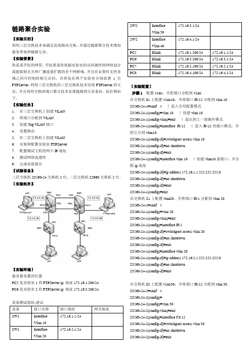
链路聚合实验【实验目的】利用三层交换技术来满足高效路由交换,并通过链路聚合技术增加服务带宽和链路冗余。
【实验背景】你是某学院的网管,学院要求你依据实验室的访问属性将网络划分成能限制无关和广播流量扩散的多个网桥域,并且在必要时支持各域之间可控制的相互访问。
具体是在两个实验室分别部署1台FTPServer,利用三层交换机的三层交换机技术实现FTPServer的互访,并且利用交换的端口聚合技术实现链路的冗余备份。
拓扑图如下。
【实验任务】1.在三层交换机上创建VLAN2.将端口分配到VLAN3.创建Tag VLAN接口4.设置路由5.在二层交换机上创建VLAN6.安装和配置实验室FTPServer7.配置测试主机的网卡IP地址8.测试网络连通性9.完成实验报告【试验设备】:三层交换机S3560-24交换机2台;二层交换机S2960交换机2台。
【实验拓扑】:【实验环境】服务器布置的位置PC5是实验室1的FTPServer ip 地址172.16.1.200/24PC6是实验室2的FTPServer ip 地址172.16.3.200/24设备测试地址-建议【实验配置】步骤1 配置vlan,并把端口分配到vlan在交换机S1上配置vlan10,并将端口f0/12分配到vlan 10S3560-24-1#conf t !进入全局配置模式S3560-24-1(config)#vlan 10 !创建vlan 10S3560-24-1(config-vlan)#exit !退出到上一级操作模式S3560-24-1(config)#interface f0/12 !进入f0/12的接口模式,并把它分到vlan10S3560-24-1(config-if)#switchport access vlan 10S3560-24-1(config-if)#no shutdownS3560-24-1(config-if)#exitS3560-24-1(config)#interface vlan 10 !创建vlan10虚接口,并分配ip地址S3560-24-1(config-if)#ip address 172.16.1.1 255.255.255.0S3560-24-1(config-if)#no shutdownS3560-24-1(config-if)#exitS3560-24-1(config)#exit在交换机S1上配置vlan20,并将端口f0/1分配到vlan 20S3560-24-1#conf tS3560-24-1(config)#vlan 20S3560-24-1(config-vlan)#exitS3560-24-1(config)#interface f0/1S3560-24-1(config-if)#switchport access vlan 20S3560-24-1(config-if)#no shutdownS3560-24-1(config-if)#exitS3560-24-1(config)#interface vlan 20S3560-24-1(config-if)#ip address 172.16.2.1 255.255.255.0S3560-24-1(config-if)#no shutdownS3560-24-1(config-if)#exit在交换机S2上配置vlan30,并将端口f0/12分配到vlan 30S3560-24-2#conf tS3560-24-2(config)#S3560-24-2(config)#vlan 30S3560-24-2(config-vlan)#exitS3560-24-2(config)#interface f 0/12S3560-24-2(config-if)#switchport access vlan 30S3560-24-1(config-if)#no shutdownS3560-24-2(config-if)#exitS3560-24-2(config)#interface vlan 30S3560-24-2(config-if)#ip address 172.16.3.1 255.255.255.0S3560-24-1(config-if)#no shutdownS3560-24-2(config-if)#exit在交换机S2上配置vlan40,并将端口f0/1分配到vlan 40S3560-24-2(config)#vlan 40S3560-24-2(config-vlan)#exitS3560-24-2(config)#interface f 0/1S3560-24-2(config-if)#switchport access vlan 40S3560-24-1(config-if)#no shutdownS3560-24-2(config-if)#exitS3560-24-2(config)#interface vlan 40S3560-24-2(config-if)#ip address 172.16.4.1 255.255.255.0S3560-24-2(config-if)#no shutdownS3560-24-2(config-if)#exit步骤2 创建tag vlan接口在交换机S1上创建Tag VLAN接口S3560-24-1(config)#interface port-channel 1 !创建聚合端口AG1 S3560-24-1(config-if)#switchport mode trunk !配置AG的模式为trunkS3560-24-1(config-if)#exitS3560-24-1(config)#interface range fastEthernet 0/2-3 !进入接口f0/2和f0/3S3560-24-1(config-if)#exitS3560-24-1(config-if-range)# channel –group 1 mode on !配置接口f0/2和f0/3属于AG1S3560-24-1(config-if-range)#endS3560-24-1(config)#show etherchannel summary在交换机S2上创建Tag VLAN接口S3560-24-2(config)#interface port-channel 1S3560-24-2(config-if)#switchport mode trunkS3560-24-2(config-if)#exitS3560-24-2(config)#interface range fastEthernet 0/2-3S3560-24-2(config-if)#exitS3560-24-2(config-if-range)# channel –group 1 mode onS3560-24-2(config-if-range)#endS3560-24-2(config)#show etherchannel summary步骤3在交换机上配置路由在交换机S1上配路由S3560-24-1(config)#ip routingS3560-24-1(config)#router rip !开启rip协议进程S3560-24-1(config-router)#network 172.16.1.0 S3560-24-1(config-router)#network 172.16.2.0S3560-24-1 (config-router)#version 2S3560-24-1(config-router)#end在交换机S2上配路由S3560-24-2(config)#ip routingS3560-24-2(config)#router ripS3560-24-2(config-router)#network 172.16.3.0S3560-24-2(config-router)#network 172.16.4.0S3560-24-2 (config-router)#version 2S3560-24-2(config-router)#end测试命令:Show ip interfaceShow ip route配置测试网卡IP地址:Pc5 172.16.1.100/24Pc7 172.16.2.100/24Pc6 172.16.3.100/24Pc8 172.16.4.100/24测试:在s1/s2交换机上ping 各自的网关.在pc上ping各自网关和各pc.【注意事项】1.两台交换机之间相连的端口应该设置为tag vlan模式。
Exp3_交换机间的聚合链路

2014.10目录交换机聚合链路连接配置实验 (2)1 范围 (2)2 规范性引用文件 (2)3 术语和定义 (2)3.1 交换机 (2)3.2 Vlan (2)3.3 交换机接口类型 (2)3.4 Access接口 (2)3.5 Trunk接口 (2)3.6 Hybrid接口 (3)3.7 接口聚合(Aggregation) (3)4 符号、代号和缩略语 (3)5 双交换机组网配置 (4)5.1 工程需求 (4)5.2 工程准备 (4)5.3 创建拓扑文件 (4)5.4 测试通信畅通性 (5)5.5 配置交换机 (6)6 验收总结 (10)7 培训结果评估 (10)交换机聚合链路连接配置实验1 范围本实训操作指导书提供信息通信专业人才技术技能操作及考核标准。
本实训操作指导书适用于信息通信专业人才。
2 规范性引用文件下列文件对于本文件的应用是必不可少的。
凡是注日期的引用文件,仅注日期的版本适用于本文件。
凡是不注日期的引用文件,其最新版本(包括所有的修改单)适用于本文件。
3 术语和定义下列术语和定义适用于本文件。
3.1 交换机交换机(Switch)是一种用于电信号转发的网络设备。
它可以为接入交换机的任意两个网络节点提供独享的电信号通路。
最常见的交换机是以太网交换机。
3.2 VlanVLAN(Virtual Local Area Network),即虚拟局域网,VLAN是一种将局域网设备从逻辑上划分成一个个区域,从而实现虚拟工作组的数据交换技术。
这一新兴技术主要应用于交换机和路由器中,但主流应用还是在交换机之中。
在交换机上Vlan的实现方式通常是为接口编组,每组分配一个唯一编码。
编码相同的接口归属于同一Vlan,连接在这些接口上的终端可以通过交换机互相通信。
编码不同的接口归属于不同Vlan,连接在这些接口上的终端不可以通过交换机跨越Vlan 互相通信。
3.3 交换机接口类型在已划分Vlan的交换机上,接口依照其对待数据包的方式可以被分为三类:Access接口、Trunk接口、Hybrid接口。
- 1、下载文档前请自行甄别文档内容的完整性,平台不提供额外的编辑、内容补充、找答案等附加服务。
- 2、"仅部分预览"的文档,不可在线预览部分如存在完整性等问题,可反馈申请退款(可完整预览的文档不适用该条件!)。
- 3、如文档侵犯您的权益,请联系客服反馈,我们会尽快为您处理(人工客服工作时间:9:00-18:30)。
内容:VTP+链路聚合
网络拓扑:
1号交换机的配置
Switch(config)#vtp domain sanzu
Switch(config)#vtp password cisco//密码
Switch(config)#vtp mode server模式
Switch(config)#exit
Switch#conf t
Switch(config)#int range f0/1-2
Switch(config-if-range)#channel-group 1 mode on Switch#conf t
Switch(config)#int port-channel 1
Switch(config-if)#switchport trunk encapsulation dot1q Switch(config-if)#switchport mode trunk
Switch#conf t
Switch#conf t
Switch(config)#int range f0/3-4
Switch(config-if-range)#channel-group 2 mode on Switch#conf t
Switch(config)#int port-channel 2
Switch(config-if)#switchport trunk encapsulation dot1q Switch(config-if)#switchport mode trunk
为vlan配网关:
Switch(config)# vlan 10
Switch(config)# vlan 20
Switch(config)# vlan 30
Switch(config)#int vlan 10
Switch(config-if)#ip add 192.168.1.1 255.255.255.0 Switch(config-if)#int vlan 20
Switch(config-if)#ip add 192.168.2.1 255.255.255.0 Switch(config-if)#int vlan 30
Switch(config-if)#ip add 192.168.3.1 255.255.255.0 Switch#show ip int b
2号交换机的配置
Switch>en
Switch#conf t
Switch(config)#vtp domain sanzu
Switch(config)#vtp password cisco
Switch(config)#vtp mode client
Switch(config)#int range f0/1-2
Switch(config-if-range)#channel-group 1 mode on Switch(config-if)#exit
Switch(config)#int port-channel 1
Switch(config-if)#switchport mode trunk
Switch(config-if)#exit
划分vlan:
Switch(config)#int range f0/3
Switch(config-if-range)#switchport access vlan 10 Switch(config-if-range)#exit
Switch(config)#int range f0/4
Switch(config-if-range)#switchport access vlan 20 3号交换机的配置
Switch>en
Switch#conf t
Switch(config)#vtp domain sanzu
Switch(config)#vtp password cisco//密码
Switch(config)#vtp mode client模式
Switch(config)#int range f0/1-2
Switch(config-if-range)#channel-group 2 mode on Switch(config-if)#exit
Switch(config)#int port-channel 2
Switch(config-if)#switchport mode trunk
Switch(config-if)#exit
划分vlan:
Switch(config)#int range f0/3
Switch(config-if-range)#switchport access vlan 10 Switch(config-if-range)#exit
Switch(config)#int range f0/4
Switch(config-if-range)#switchport access vlan 30。
