cisco+端口链路聚合配置
思科端口汇聚配置

链路聚合有成端口聚合,端口捆绑,英文名port trunking.功能是将交换机的多个低带宽端口捆绑成一条高带宽链路,可以实现链路负载平衡。
避免链路出现拥塞现象。
通过配置,可通过两个三个或是四个端口进行捆绑,分别负责特定端口的数据转发,防止单条链路转发速率过低而出现丢包的现象。
Trunking的优点:价格便宜,性能接近千兆以太网;不需要重新布线,也无需考虑千兆网传输距离极限问题;trunking可以捆绑任何相关的端口,也可以随时取消设置,这样提供了很高的灵活性还可以提供负载均衡能力以及系统容错。
命令:port-group mode {active|passive|on}no port-group功能:将物理端口加入Port Channel,该命令的no 操作为将端口从Port Channel 中去除参数:为Port Channel 的组号,范围为1~16;active(0)启动端口的LACP 协议,并设置为Active 模式;passive(1)启动端口的LACP 协议,并且设置为Passive 模式;on(2)强制端口加入Port Channel,不启动LACP 协议。
举例:在Ethernet0/0/1 端口模式下,将本端口以active 模式加入port-groupSwitch(Config-Ethernet0/0/1)#port-group 1 mode active命令:interface port-channel功能:进入汇聚接口配置模式命令模式:全局配置模式举例:进入port-channel1 配置模式Switch(Config)#interface port-channel 1Switch(Config-If-Port-Channel1)#举例1:如果交换机Switch1 上的1,2,3 端口都是access 口,并且都属于vlan 1,将这三个端口以active 方式加入group 1,Switch2 上6,8,9 端口为trunk 口,并且是allow all,将这三个端口以passive 方式加入group 2,将以上对应端口分别用网线相连。
cisco怎么配置聚合端口聚合

cisco怎么配置聚合端口聚合有网友这么问小编“cisco怎么配置聚合端口聚合?”,店铺在网上搜索了一些资料,供大家参考。
所谓端口聚合,指的是把两个或多个物理端口捆绑成一个逻辑链路,两设备多个端口两两相连,从而增加链路带宽,可起到负载均衡的作用,而且多条线路间还能形成冗余备份。
比方说,两个千M端口聚合后带宽就有2G,如果其中一个端口down了或线路出问题了并不影响网络的正常运行,只是带宽变成了1G而已,增加了网络的可靠性。
端口聚合分手动和自动协商两种方式:SW0(config)#interface range gigabitEthernet0/1-2 //进入端口G0/1与G0/2SW0(config-if-range)#channel-group 1 mode ? //查看端口聚合模式active Enable LACP unconditionally //主动发送LACPDU报文auto Enable PAgP only if aPAgP device is detected //相当于passive(PAgP)desirable Enable PAgP unconditionally //相当于active(PAgP) on Enable Etherchannel only //手动方式(两端都on,配置后会使用PAgP)passive Enable LACP only if a LACP device is detected //被动接收LACPDU报文SW0(config-if-range)#channel-group 1 modea ctiveon不属于任何一个协议,但配置后会使用PagP协议,两端都需on;如果服务不支持任何协商协议,推荐此模式。
PAgP(Port Aggregation Protocol):CISCO私有协议,有auto 和desirable模式。
PAgP 可以用来自动创建快速EtherChannel 链路。
3、思科模拟器链路聚合命令hao
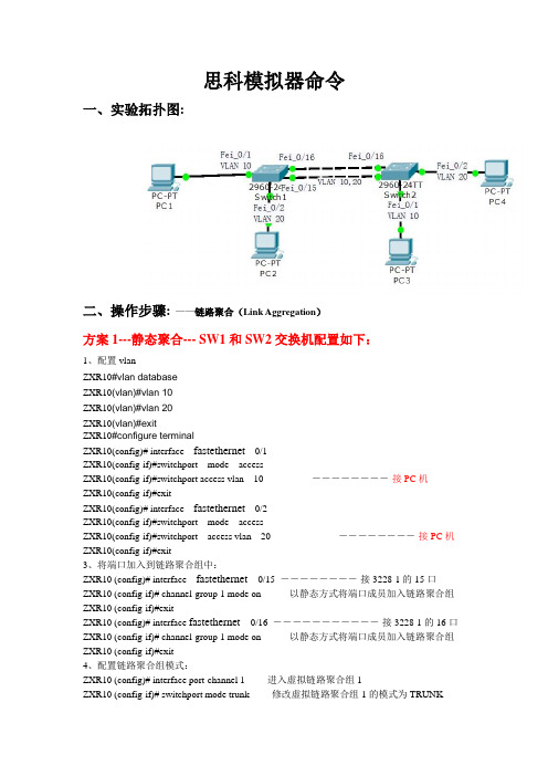
思科模拟器命令一、实验拓扑图:二、操作步骤:——链路聚合(Link Aggregation)方案1---静态聚合--- SW1和SW2交换机配置如下:1、配置vlanZXR10#vlan databaseZXR10(vlan)#vlan 10ZXR10(vlan)#vlan 20ZXR10(vlan)#exitZXR10#configure terminalZXR10(config)# interface fastethernet0/1ZXR10(config-if)#switchport mode accessZXR10(config-if)#switchport access vlan 10 ――――――――-接PC机ZXR10(config-if)#exitZXR10(config)# interface fastethernet0/2ZXR10(config-if)#switchport mode accessZXR10(config-if)#switchport access vlan 20 ――――――――-接PC机ZXR10(config-if)#exit3、将端口加入到链路聚合组中:ZXR10 (config)# interface fastethernet 0/15 ――――――――-接3228-1的15口ZXR10 (config-if)# channel-group 1 mode on---------以静态方式将端口成员加入链路聚合组ZXR10 (config-if)#exitZXR10 (config)# interface fastethernet 0/16 ―――――――――――-接3228-1的16口ZXR10 (config-if)# channel-group 1 mode on---------以静态方式将端口成员加入链路聚合组ZXR10 (config-if)#exit4、配置链路聚合组模式:ZXR10 (config)# interface port-channel 1-------进入虚拟链路聚合组1ZXR10 (config-if)# switchport mode trunk-------修改虚拟链路聚合组1的模式为TRUNKZXR10(config-if)#switchport trunk allowed vlan 10,20----虚拟链路聚合组1承载VLAN 10,20 ZXR10 (config)#exit(SW2交换机配置同SW-1一样)方案2 –动态链路聚合---SW1和SW2交换机配置如下:1、配置vlanZXR10#vlan databaseZXR10(vlan)#vlan 10ZXR10(vlan)#vlan 20ZXR10(vlan)#exitZXR10#configure terminalZXR10(config)# interface fastethernet0/1ZXR10(config-if)#switchport mode accessZXR10(config-if)#switchport access vlan 10 ――――――――-接PC机ZXR10(config-if)#exitZXR10(config)# interface fastethernet0/2ZXR10(config-if)#switchport mode accessZXR10(config-if)#switchport access vlan 20 ――――――――-接PC机ZXR10(config-if)#exit3、将端口加入到链路聚合组中:ZXR10 (config)# interface fastethernet 0/15 ――――――――-接3228-1的15口ZXR10 (config-if)# channel-protocol lacp--------设置端口聚合模式为动态模式ZXR10 (config-if)# channel-group 1 mode active(/passive)---------以动态方式将端口成员加入链路聚合组ZXR10 (config-if)#exitZXR10 (config)# interface fastethernet 0/16 ―――――――――――-接3228-1的16口ZXR10 (config-if)# channel-protocol lacp--------设置端口聚合模式为动态模式ZXR10 (config-if)# channel-group 1 mode active(/passive)---------以动态方式将端口成员加入ZXR10 (config-if)#exit4、配置链路聚合组模式:ZXR10 (config)# interface port-channel 1ZXR10 (config-if)# switchport mode trunkZXR10(config-if)#switchport trunk allowed vlan 10,20ZXR10 (config)#exit(SW2交换机配置同SW-1一样)注:聚合模式设置为on时端口运行静态trunk,参与聚合的两端都需要设置为on模式。
Cisco交换机链路聚合
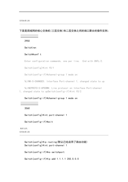
实用标准文案下面是局域网的核心交换机(三层交换)和二层交换之间的端口聚合的操作实例:2950Switch>enSwitch#conf tEnter configuration commands, one per line. End with CNTL/Z.Switch(config)#int f0/1Switch(config-if)#channel-group 1 mode on%LINK-5-CHANGED: Interface Port-channel 1, changed state to up%LINEPROTO-5-UPDOWN: Line protocol on Interface Port-channel1, changed state to upSwitch(config-if)#int f0/2Switch(config-if)#channel-group 1 mode on3560Switch(config)#int port-channel 1Switch(config-if)#exit精彩文档.实用标准文案Switch(config)#ip routing(默认已经启用了路由功能)Switch(config)#int port-channel 1Switch(config-if)#no switchportSwitch(config-if)#ip add 1.1.1.1 255.0.0.0Switch(config-if)#no shutSwitch(config-if)#exitSwitch(config)#int f0/1Switch(config-if)#no switchport%LINEPROTO-5-UPDOWN: Line protocol on Interface FastEthernet0/1, changed state to down%LINEPROTO-5-UPDOWN: Line protocol on Interface FastEthernet0/1, changed state to upSwitch(config-if)#Switch(config-if)#no ip addSwitch(config-if)#channel-group 1 mode ?active Enable LACP unconditionallyauto Enable PAgP only if a PAgP device is det ected 精彩文档.实用标准文案desirable Enable PAgP unconditionallyon Enable Etherchannel onlypassive Enable LACP only if a LACP device is detectedSwitch(config-if)#channel-group 1 mode on%LINK-5-CHANGED: Interface Port-channel 1, changed state to up%LINEPROTO-5-UPDOWN: Line protocol on Interface Port-channel1, changed state to upSwitch(config-if)#Switch(config-if)#int f0/2Switch(config-if)#no switchport%LINEPROTO-5-UPDOWN: Line protocol on Interface FastEthernet0/2, changed state to down%LINEPROTO-5-UPDOWN: Line protocol on Interface FastEthernet0/2, changed state to upSwitch(config-if)#no ip add精彩文档.实用标准文案Switch(config-if)#no ip addressSwitch(config-if)#channel-group 1 mode onSwitch(config-if)#exitSwitch(config)#int f0/3Switch(config-if)#no switchport%LINEPROTO-5-UPDOWN: Line protocol on Interface FastEthernet0/3, changed state to down%LINEPROTO-5-UPDOWN: Line protocol on Interface FastEthernet0/3, changed state to upSwitch(config-if)#ip add 2.2.2.1 255.0.0.0Switch(config-if)#no shut端口聚合可使流量在多条物理链路上负载均衡,同时也起到了链路的备份作用。
cisco怎么配置聚合端口

cisco怎么配置聚合端口cisco怎么配置聚合端口?店铺在网上找了一些教程及命令,需要的朋友可以参考下。
作为一种内部网关协议或IGP(内部网关协议),路由选择协议应用于 AS 系统。
那么cisco怎么设置路由rip协议?店铺整理了相关资料,供大家参考。
端口的聚合有两种方式,一种是手动的方式,一个是自动协商的方式。
(1)手动方式这种方式很简单,设置端口成员链路两端的模式为“on”。
命令格式为: channel-group <number组号> mode on(2)自动方式自动方式有两种协议:PAgP(Port Aggregation Protocol)和LACP(Link aggregation Control Protocol)。
PAgP:Cisco设备的端口聚合协议,有auto和desirable两种模式。
auto模式在协商中只收不发,desirable模式的端口收发协商的数据包。
LACP:标准的端口聚合协议802.3ad,有active和passive两种模式。
active相当于PAgP的auto,而passive相当于PAgP的desirable。
1:在(config)#模式下,输入int port-channel ID(1-64)2:假设要把F0/23和F0/24聚合,那么分别在起端口配置里面输入:switchport trunkencapsulation dot1qswitchport mode trunk(假设有多个VLAN)duplex fullspeed 100no cdp enablechannel-group 1 mode on(这里的1就是开始创建的数字),或者直接在需要做端口聚合的端口上执行下面命令int port-ch 10channel-g 10 mode acchannel-g p lacp(panp)然后只要在对端交换机也做同样配置就可以了以下是以思科2950以及7200设备为例的具体操作:Cat2950的配置:Cat2950#conf tCat2950(config)#vtp mode serverCat2950(config)#vtp domain ciscoCat2950(config)#vlan 10Cat2950(config-vlan)#exitCat2950(config)#vlan 20Cat2950(config-vlan)#exitCat2950(config)#int range fa0/5 - 14Cat2950(config-if-range)#switchport access vlan 10Cat2950(config-if-range)#exitCat2950(config)#int range fa0/15 - 26Cat2950(config-if-range)#switchport access vlan 20Cat2950#conf tCat2950(config)#int vlan 10Cat2950(config-if)#ip address 10.10.10.10 255.255.255.0Cat2950(config)#ip default-gateway 10.10.10.1Cat2950(config-if)#no shutdownCat2950(config)#int port-channel 1Cat2950(config-if)#exitCat2950(config)#int fa0/2Cat2950(config-if)#channel-group 1 mode onCat2950(config-if)#exitCat2950(config)#int fa0/3Cat2950(config-if)#channel-group 1 mode onCat2950(config-if)#exitCat2950(config)#int port-channel1Cat2950(config-if)#switchport mode trunkCat2950(config-if)#switchport trunk native vlan 10cisco7200的配置:Cisco7200#conf tCisco7200(config)#int port-channel 1Cisco7200(config-if)#exitCisco7200(config)#int fa3/0Cisco7200(config-if)#channel-group 1Cisco7200(config-if)#exitCisco7200(config)#int fa4/0Cisco7200(config-if)#channel-group 1Cisco7200(config-if)#exitCisco7200(config)#int port-channel 1.10Cisco7200(config-subif)#encapsulation dot1Q 10 native Cisco7200(config-subif)#ip address 10.10.10.1 255.255.255.0 Cisco7200(config-subif)#exitCisco7200(config)#int port-channel 1.20Cisco7200(config-subif)#encapsulation dot1Q 20Cisco7200(config-subif)#ip address 10.10.11.1 255.255.255.0 Cisco7200(config-subif)#exitCisco7200(config)#exit以上内容来自互联网,希望对大家有所帮助。
Cisco链路聚合协议实验
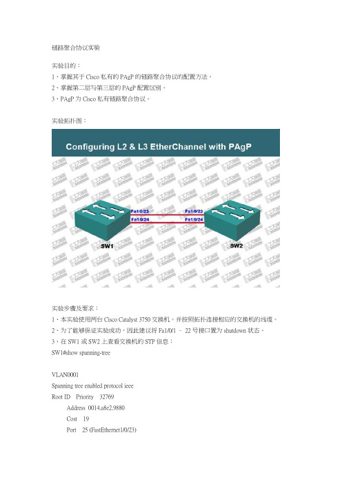
链路聚合协议实验实验目的:1、掌握其于Cisco私有的PAgP的链路聚合协议的配置方法。
2、掌握第二层与第三层的PAgP配置区别。
3、PAgP为Cisco私有链路聚合协议。
实验拓扑图:实验步骤及要求:1、本实验使用两台Cisco Catalyst 3750交换机。
并按照拓扑连接相应的交换机的线缆。
2、为了能够保证实验成功,因此建议将Fa1/0/1 – 22号接口置为shutdown状态。
3、在SW1或SW2上查看交换机的STP信息:SW1#show spanning-treeVLAN0001S panning tree enabled protocol ieeeR oot ID Priority 32769Address 0014.a8e2.9880Cost 19Port 25 (FastEthernet1/0/23)Hello Time 2 sec M ax Age 20 sec F orward Delay 15 secB ridge ID P riority 32769 (priority 32768 sys-id-ext 1)Address 0014.a8f1.9880Hello Time 2 sec M ax Age 20 sec F orward Delay 15 secAging Time 300Interface R ole Sts Cost P rio.Nbr Type---------------- ---- --- --------- -------- --------------------------------Fa1/0/23 R oot FWD 19 128.25 P2pFa1/0/24 A ltn BLK 19 128.26 P2p[stanley1]SW1#4、STP协议虽然可以避免网络环路的问题。
但是其仍然不能充分的利用冗余的链路带宽。
为了解决链路带宽的问题,可以实施PAgP的链路聚合。
Cisco交换机端口聚合(EtherChannel)

Cisco交换机端口聚合(EtherChannel)端口聚合,英文简称EtherChannel(以太通道)是由Cisco研发的,应用于交换机之间的多链路捆绑技术。
它的基本原理是:将两个设备间多条物理链路捆绑在一起组成一条逻辑链路,从而达到带宽倍增的目的(这条逻辑链路带宽相当于物理链路带宽之和)。
除了增加带宽外,端口聚合还可以在多条链路上均衡分配流量,起到负载分担的作用;当一条或多条链路故障时,只要还有链路正常,流量将转移到其它的链路上,整个过程在几毫秒内完成,从而起到冗余的作用,增强了网络的稳定性和安全性。
两台交换机之间是否形成EtherChannel也可以用协议自动协商。
目前有两个协商协议:PAgP和LACP,PAgP(端口汇聚协议Port Aggregation Protocol)是Cisco私有的协议,而LACP(链路汇聚控制协议Link Aggregation Control Protocol)是基于IEEE 802.3ad的国际标准,是一种实现链路动态聚合的协议。
Switch(config-if-range)#channel-group 1 mode ? #通过此命令在交换机查看端口聚合可以使用的协议active Enable LACP unconditionally #主动发送LACP报文auto Enable PAgP only if a PAgP device is detected #被动发送PAgP报文desirable Enable PAgP unconditionally #主动发送PAgP报文on Enable Etherchannel only #手动设置,需要两边都设置成onpassive Enable LACP only if a LACP device is detected #被动接收LACP报文端口聚合说明:1、Cisco最多允许EtherChannel绑定8个端口;(1)、如果是百兆网络,总带宽可达1.6Gbit/s;(2)、如果是千兆网络,总带宽可达16Gbit/s。
GNS3_C3640做Cisco端口聚合实验(修改版)

GNS3_C3640做Cisco端口聚合实验(修改版)端口的聚合有两种方式,一种是手动的方式,一个是自动协商的方式。
(1)手动方式这种方式很简单,设置端口成员链路两端的模式为“on”。
命令格式为:channel-group <number组号> mode on(2)自动方式自动方式有两种协议:PAgP(Port Aggregation Protocol)和LACP(Link aggregation Control Protocol)。
PAgP:Cisco设备的端口聚合协议,有auto和desirable两种模式。
auto模式在协商中只收不发,desirable模式的端口收发协商的数据包。
LACP:标准的端口聚合协议802.3ad,有active和passive两种模式。
active相当于PAgP的auto,而passive相当于PAgP的desirable。
1:在(config)#模式下,输入int port-channel ID(1-64)2:假设要把F0/23和F0/24聚合,那么分别在起端口配置里面输入:switchport trunkencapsulation dot1qswitchport mode trunk(假设有多个VLAN)duplex fullspeed 100no cdp enablechannel-group 1 mode on(这里的1就是开始创建的数字),或者直接在需要做端口聚合的端口上执行下面命令int port-ch 10channel-g 10 mode acchannel-g p lacp(panp)然后只要在对端交换机也做同样配置就可以了.交换机连接拓扑图如下:步骤:一、两台三层交换机SW0、SW1上分别创建vlan:Sw0#vlan databaseSw0(vlan)#vlan 10Sw0(vlan)#vlan 11Sw0(vlan)#exit二、在Sw0交换机上将端口fa0/1-2加入到vlan10中,端口fa0/3加入到vlan 11中Sw0(configure)#int range fa0/1-2Sw0(configure-if-range)#switchport access vlan 10Sw0(configure-if-range)#exitSw0(configure)#int fa0/3Sw0(configure-if)# switchportacessvlan 11Sw0(configure)#exit三、在Sw1交换机上将fa0/1-2号端口加入到vlan 10中,将fa0/3号端口加到vlan 100中Sw1#conf tSw1(configure)#int range fa0/1-2Sw1(configure-if-range)#switchport access vlan 10Sw1(configure-if-range)#exitSw1(configure)#int fa0/3Sw1(configure-if)#switchport access vlan 100Sw1(configure-if)#exit四、在Sw0和Sw1交换机上为每个vlan配置虚拟ip地址Sw0#conf tSw0(configure)#intvlan 10Sw0(configure-if-vlan)#ip address 192.168.10.253 255.255.255.0Sw0(configure-if-vlan)#no shutdownSw0(configure-if-vlan)#exitSw0(configure)#intvlan 11Sw0(configure-if-vlan)#ipaddresss 192.168.11.254 255.255.255.0Sw0(configure-if-vlan)#no shutdownSw0(configure-if-vlan)#exitSw1#conf tSw1(configure)#intvlan 10Sw1(configure-if-vlan)#ip address 192.168.10.254 255.255.255.0Sw1(configure-if-vlan)#no shutdownSw1(configure-if-vlan)#exitSw1(configure)#intvlan 100Sw1(configure-if-vlan)#ip address 192.168.100.254 255.255.255.0Sw1(configure-if-vlan)#no shutdownSw1(configure-if-vlan)#exit五、将Sw0和Sw1交换机相连的fa0/1-2口进行聚合Sw0#conf tSw0(configure)#int range fa0/1-2Sw0(configure-if-range)#channel-group 1 mode on(模拟器GNS3下只能自动的)//Sw0(configure-if-range)#channel-group 1 modedesirable Sw0(configure-if-range)#exitSw1#conf tSw1(configure)#int range fa0/1-2Sw0(configure-if-range)#channel-group 1 mode on(模拟器GNS3下只能自动的)//Sw0(configure-if-range)#channel-group 1 mode desirable Sw1(configure-if-range)#exit六、在Sw0和Sw1交换机上将聚合端口设置为trunk口Sw0#conf tSw0(configure)#int port-channel 1Sw0(configure-if)#switchport mode trunkSw0(configure-if)#switchport trunk native vlan 10Sw0(configure-if)#exitSw1#conf tSw1(configure)#int port-channel 1Sw1(configure-if)#switchport mode trunkSw1(configure-if)#switchport trunk native vlan 10Sw1(configure-if)#exit七、在Sw0和Sw1交换机上设置默认路由(当然你也可以设置能实现路由功能的协议)Sw0#conf tSw0(configure)#ip route 0.0.0.0 0.0.0.0 192.168.10.254Sw0(configure)#exitSw1#conf tSw1(configure)#ip route 0.0.0.0 0.0.0.0 192.168.10.253Sw1(configure)#exit八、测试1、这里是用C3640路由器模拟PC机PC0#conf tPC0(config)#no ip routingPC0(config)#ip default-gateway 192.168.11.254PC0(config)#interface fastEthernet 0/0PC0(config-if)#ip add 192.168.11.1 255.255.255.0PC0(config-if)#no shutdownPC1#conf tPC1(config)#no ip routingPC1(config)#ip default-gateway 192.168.100.254PC1(config)#interface fastEthernet 0/0PC1(config-if)#ip add 192.168.100.1 255.255.255.0PC1(config-if)#no shutdown2、VPCS端在PC0客户端设置其ip地址为:192.168.11.1,子网掩码为:255.255.255.0,网关地址为:192.168.11.254在PC1客户端设置其ip地址:192.168.100.1,子网掩码为:255.255.255.0,网关地址为:192.168.100.254利用PC0客户端去ping PC1客户端的ip,检查是否能够ping 即可!!!*[注意]:在对Sw0和Sw1交换机上进行端口聚合后,如果没有设置聚合端口为trunk 时,交换机两边是不能够被ping 通的。
cisco端口链路聚合配置

cisco+端口链路聚合配置端口链路聚合(Port Channel)是一种将多个物理端口组合成一个逻辑链路的技术,通过增加带宽和提供冗余性,提高网络连接的可靠性和性能。
在Cisco设备上,端口链路聚合可以通过EtherChannel实现。
EtherChannel是Cisco的一种端口聚合技术,它允许将多个物理端口绑定成一个逻辑链路。
EtherChannel可以在交换机之间或交换机与服务器之间建立,可以使用不同的协议进行链路聚合,如LACP(Link Aggregation Control Protocol)或PAgP(Port Aggregation Protocol)。
下面是一个配置EtherChannel的示例:1. 配置物理接口:首先,需要将要聚合的物理接口配置为开启状态,并设置合适的速率和双工模式。
例如,假设我们要聚合的接口为GigabitEthernet1/1和GigabitEthernet1/2,可以使用以下命令进行配置:Switch(config)interface GigabitEthernet1/1Switch(config-if)no shutdownSwitch(config-if)speed 1000Switch(config-if)duplex fullSwitch(config)interface GigabitEthernet1/2Switch(config-if)no shutdownSwitch(config-if)speed 1000Switch(config-if)duplex full2. 创建端口聚合组:接下来,需要创建一个端口聚合组,用于将物理接口绑定成一个逻辑链路。
可以使用以下命令进行配置:Switch(config)interface Port-channel1Switch(config-if)switchport mode trunkSwitch(config-if)switchport trunk allowed vlan all3. 添加物理接口到端口聚合组:将之前配置的物理接口添加到创建的端口聚合组中。
最新整理思科交换机的端口聚合口怎么配置

思科交换机的端口聚合口怎么配置像网桥那样,交换机将局域网分为多个冲突域,每个冲突域都是有独立的宽带,因此大大提高了局域网的带宽。
有时交换机和交换机,交换机和路由器之间的端口速率,不能满足实际的速率,就需要将两个以上的端口绑在一起,实现均很负载,这就需要聚合口配置,下面我们一起来看看方法步骤1、打开c i s c o模拟器---选择交换机s2960、直连线、服务器像如图连接起来。
2、选择交换机s w i t c h0进行配置----进入特权模式,将f a0/1和f a0/2端口模式配置成t r u n k。
3、将f a0/1和f a0/2加入链路组1并开启----按照目标主机地址I P数据分发来实现负荷平衡----通过s h o w e t h e r c h a n n e l s u m m a r y来查看聚合口配置情况。
4、按照交换机s w i t c h0的配置,配置s w i t c h1----可以看到刚才b l o c k的端口变绿,表示已经开通。
5、将p c0I P配置为192.168.1.2子网掩码为255.255.255.0,p c1I P配置为192.168.1.3子网掩码为255.255.255.0---p c0p i n g p c1,p c1p i n g p c0都可以p i n g通,即完成聚合口的配置。
相关阅读:交换机工作原理过程交换机工作于O S I参考模型的第二层,即数据链路层。
交换机内部的C P U会在每个端口成功连接时,通过将M A C地址和端口对应,形成一张M A C表。
在今后的通讯中,发往该M A C地址的数据包将仅送往其对应的端口,而不是所有的端口。
因此,交换机可用于划分数据链路层广播,即冲突域;但它不能划分网络层广播,即广播域。
交换机拥有一条很高带宽的背部总线和内部交换矩阵。
交换机的所有的端口都挂接在这条背部总线上,控制电路收到数据包以后,处理端口会查找内存中的地址对照表以确定目的M A C(网卡的硬件地址)的N I C(网卡)挂接在哪个端口上,通过内部交换矩阵迅速将数据包传送到目的端口,目的M A C若不存在,广播到所有的端口,接收端口回应后交换机会学习新的M A C地址,并把它添加入内部M A C地址表中。
cisco+端口链路聚合配置
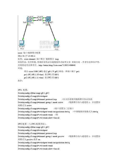
cisco 端口/链路聚合配置2011-01-27 14:46:11标签:csico channel 端口聚合链路聚合lacp原创作品,允许转载,转载时请务必以超链接形式标明文章原始出处、作者信息和本声明。
否则将追究法律责任。
/715953/486648环境:两台cisco 3560-24PS通过g0/1和g0/2相连,两端口属于po1.pc1:192.168.1.10 vlan1 接SW1的fa0/1pc2:192.168.1.11 vlan1 接SW2的fa0/1拓扑:SW1 配置:Switch(config-if)#int range g0/1-g0/2Switch(config-if-range)#switchportSwitch(config-if-range)#channel-protocol lacp //以太信道使用链路聚合协议协商Switch(config-if-range)#channel-group 1 mode active //链路聚合加入通道组1,并设置协商模式为activeSwitch(config-if-range)#switchport //端口设置为二层端口Switch(config-if-range)#switchport trunk encapsulation dot1q //中继链路封装格式为dot1q Switch(config-if-range)# swit mode trunk //将Switch(config-if-range)# swit trunk allow vlan allSW2配置(与SW1配置类似):Switch(config-if)#int range g0/1-g0/2Switch(config-if-range)#switchportSwitch(config-if-range)#channel-protocol lacpSwitch(config-if-range)#channel-group 1 mode passive //链路聚合加入通道组1,并设置协商模式为passive或者onSwitch(config-if-range)#switchport trunk encapsulation dot1qSwitch(config-if-range)# swit mode trunkSwitch(config-if-range)# swit trunk allow vlan all本文出自“菜鸟·小蜗牛”博客,请务必保留此出处/715953/486648步骤:一、两台三层交换机上创建vlan:Sw0#conf tSw0(configure)#vlan 10Sw0(configure-vlan)#exitSw0(configure)#vlan 11Sw0(configure-vlan)#exit二、在Sw0交换机上将端口fa0/1-2加入到vlan10中,端口fa0/3加入到vlan 11中Sw0(configure)#int range fa0/1-2Sw0(configure-if-range)#switchport access vlan 10Sw0(configure-if-range)#exitSw0(configure)#int fa0/3Sw0(configure-if)# switchport access vlan 11Sw0(configure)#exit三、在Sw1交换机上将fa0/1-2号端口加入到vlan 10中,将fa0/3号端口加到vlan 100中Sw1#conf tSw1(configure)#int range fa0/1-2Sw1(configure-if-range)#switchport access vlan 10Sw1(configure-if-range)#exitSw1(configure)#int fa0/3Sw1(configure-if)#switchport access vlan 100Sw1(configure-if)#exit四、在Sw0和Sw1交换机上为每个vlan 配置虚拟ip地址Sw0#conf tSw0(configure)#int vlan 10Sw0(configure-if-vlan)#ip address 192.168.10.253 255.255.255.0Sw0(configure-if-vlan)#no shutdownSw0(configure-if-vlan)#exitSw0(configure)#int vlan 11Sw0(configure-if-vlan)#ip addresss 192.168.11.254 255.255.255.0Sw0(configure-if-vlan)#no shutdownSw0(configure-if-vlan)#exitSw1#conf tSw1(configure)#int vlan 10Sw1(configure-if-vlan)#ip address 192.168.10.254 255.255.255.0Sw1(configure-if-vlan)#no shutdownSw1(configure-if-vlan)#exitSw1(configure)#int vlan 100Sw1(configure-if-vlan)#ip address 192.168.100.254 255.255.255.0 Sw1(configure-if-vlan)#no shutdownSw1(configure-if-vlan)#exit五、将Sw0和Sw1交换机相连的fa0/1-2口进行聚合Sw0#conf tSw0(configure)#int range fa0/1-2Sw0(configure-if-range)#channel-group 1 mode desirableSw0(configure-if-range)#exitSw1#conf tSw1(configure)#int range fa0/1-2Sw1(configure-if-range)#channel-gropu 1 mode desirableSw1(configure-if-range)#exit【可选做】// 六、在Sw0和Sw1交换机上将聚合端口设置为trunk口Sw0#conf tSw0(configure)#int port-channel 1加一句:sw tr en dot1qSw0(configure-i)#switchport mode trunkSw0(configure-if)#switchport trunk native vlan 10Sw0(configure-if)#exitSw1#conf tSw1(configure)#int port-channel 1Sw1(configure-if)#switchport mode trunkSw1(configure-if)#switchport trunk native vlan 10Sw1(configure-if)#exit//七、在Sw0和Sw1交换机上设置默认路由(当然你也可以设置能实现路由功能的协议)Sw0#conf tSw0(configure)#ip route 0.0.0.0 0.0.0.0 192.168.10.254Sw0(configure)#exitSw1#conf tSw1(configure)#ip route 0.0.0.0 0.0.0.0 192.168.10.253Sw1(configure)#exit八、测试在PC0客户端设置其ip地址为:192.168.11.1,子网掩码为:255.255.255.0,网关地址为:192.168.11.254在PC1客户端设置其ip地址:192.168.100.1,子网掩码为:255.255.255.0,网关地址为:192.168.100.254利用PC0客户端去ping PC1客户端的ip,检查是否能够ping 即可!!!*[注意]:在对Sw0和Sw1交换机上进行端口聚合后,如果没有设置聚合端口为trunk时,交换机两边是不能够被ping 通的。
cisco 链路聚合lacp

链路聚合Lacp 实验目的:理解并掌握链路聚合的配置及原理。
实验拓扑:实验步骤:SW1SW1(config)#interface range g0/1 - g0/2SW1(config-if-range)#channel-protocol lacpSW1(config-if-range)#channel-group 1 mode activeSW1(config-if-range)#exitSW1(config)#interface port-channel 1SW1(config-if)#switchport mode trunkSW1(config-if)#switchport trunk encapsulation dot1q SW1(config-if)#switchport nonegotiateSW1(config-if)#exitSW1(config)#^ZSW1#%SYS-5-CONFIG_I: Configured from console by console SW1#wrBuilding configuration...[OK]SW2SW2(config)#interface range g0/1 -g0/2SW2(config-if-range)#channel-protocol lacpSW2(config-if-range)#channel-group 1 mode passiveSW2(config-if-range)#exitSW2(config)#interface port-channel 1SW2(config-if)#switchport mode trunkSW2(config-if)#switchport trunk encapsulation dot1q SW2(config-if)#switchport nonegotiateSW2(config-if)#exitSW2(config)#exitSW2#wrBuilding configuration...[OK]分析:SW1SW2以上显示,链路聚合完成。
cisco链路聚合实验-电脑资料
cisco链路聚合实验-电脑资料端口聚合也叫做以太通道(ethernetchannel),主要用于交换机之间连接,。
由于两个交换机之间有多条冗余链路的时候,STP会将其中的几条链路关闭,只保留一条,这样可以避免二层的环路产生。
但是,失去了路径冗余的优点,因为STP的链路切换会很慢,在50s左右。
使用以太通道的话,交换机会把一组物理端口联合起来,做为一个逻辑的通道,也就是channel-group,这样交换机会认为这个逻辑通道为一个端口。
这样有几个优点:1. 带宽增加,带宽相当于组成组的端口的带宽总和。
2. 增加冗余,只要组内不是所有的端口都down掉,两个交换机之间仍然可以继续通信。
3. 负载均衡,可以在组内的端口上配置,使流量可以在这些端口上自动进行负载均衡。
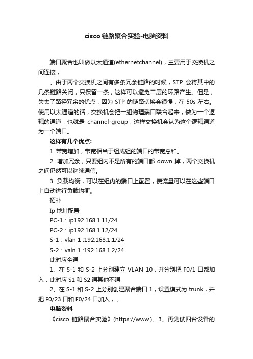
拓扑Ip地址配置PC-1:ip192.168.1.11/24PC-2:ip192.168.1.12/24S-1:vlan 1 :192.168.1.1/24S-2:valn 1 :192.168.1.2/24此时应全通1、在S-1和S-2上分别建立VLAN 10,并分别把F0/1口都加入,此时应S1和S2通其他不通2、在S-1和S-2上分别创建聚合端口1,设置模式为trunk,并把F0/23口和F0/24口加入,,电脑资料《cisco 链路聚合实验》(https://www.)。
3、再测试四台设备的互通性(应该是S-1和S-2互通,PC1和PC2互通,其他不通)4、断掉其中一条链路器网络不受影响命令提示:一、思科端口聚合配置:(只是增加带宽,不会起到备用作用)1.创建聚合端口,并设置为trunk模式:SWA(config)#interface port-channel 1SWA(config-if)#switchport mode trunkSWA(config-if)#exit2.以手动方式把端口加入聚合端口中:SWA(config)# interface range fastethernet 0/23 – 24SWA(config-if)#channel-group 1 mode onSWA(config-if)#exit3.设置聚合端口的负载平衡:SWA(config)#port-channel load-balance [dst-mac, src-mac] //dst-mac根据目的mac负载//sec-mac根据源mac负载4.查看聚合端口:SWA#show etherchannel summaryshowrunning-config的显示。
配置聚合端口AP(思科版)

任务2 配置聚合端口一、任务分析某公司有两台交换机,一台交换机连接网络中的多台服务器,另外一台交换机连接员工的PC,两台交换机之间通过一条网线互连,员工要频繁访问服务器。
为了提高交换机之间的传输带宽,需要在交换机上作适当的配置。
网络结构图二、端口聚合把多个物理链接捆绑在一起形成一个简单的逻辑链接,称为一个端口聚合(Aggregate Port,AP),也称链路聚合。
AP是链路带宽扩展的一个重要途径,符合IEEE 802.3ad标准,它可以把多个端口的带宽叠加起来使用。
尽管AP也存在冗余链路,但不会引起广播风暴。
全双工快速以太网端口形成的AP最大可以达到800Mbsp,千兆以太网接口形成的AP最大可以达到8Gbsp。
三、流量平衡当AP中的一条成员链路断开时,系统会将该链路的流量分配到AP中的其他有效链路上去,从而实现备份,AP中一条链路收到的广播或者多播报文不会被转发到其他链路上。
AP根据报文的MAC地址或IP地址进行流量平衡,把流量平均地分配到AP的成员链路中去,以充分利用网络的带宽。
AP是链路带宽扩展的一个重要途径,提供链路备份和流量平衡。
锐捷S2126G交换机最大支持6个AP,每个AP最多能包含8个端口。
一个端口同时只能属于一个AP。
一旦AP配置完成,则AP配置将应用到所有的AP成员端口上,如果一个端口加入AP,则该端口的与AP相同类别的特性将被AP的配置所取代。
当一个端口从AP中删除时,则端口的属性将恢复为其加入AP前的属性。
AP配置可分为两步:①建立一个AP;②将指定端口加入AP中。
参考命令:aggregatePort load-balance !锐捷命令格式:aggregatePort load-balance {dst-mac | src-mac |ip}!锐捷命令功能:配置AP的流量平衡。
参数说明:dst-mac表示根据报文的目的地址把报文分配到各个链路中;ip表示根据报文源IP与目的IP进行流量分配;src-mac表示根据报文的源MAC地址把报文分配到各个链路中。
Cisco交换机链路聚合

下面是局域网的核心交换机(三层交换)和二层交换之间的端口聚合的操作实例:2950Switch>enSwitch#conf tEnter configuration commands, one per line. End with CNTL/Z.Switch(config)#int f0/1Switch(config-if)#channel-group 1 mode on%LINK-5-CHANGED: Interface Port-channel 1, changed state to up%LINEPROTO-5-UPDOWN: Line protocol on Interface Port-channel 1, changed state to upSwitc h(config-if)#int f0/2Switch(config-if)#channel-group 1 mode on3560Switch(config)#int port-channel 1Switch(config-if)#exitSwitch(config)#ip routing(默认已经启用了路由功能)Switch(config)#int port-channel 1Switch(config-if)#no switchportSwitch(config-if)#ip add 1.1.1.1 255.0.0.0Switch(config-if)#no shutSwitch(config-if)#exitSwitch(config)#int f0/1Switch(config-if)#no switchport%LINEPROTO-5-UPDOWN: Line protocol on Interface FastEthernet0/1, changed state to down%LINEPROTO-5-UPDOWN: Line protocol on Interface FastEthernet0/1, changed state to upSwit ch(config-if)#Switch(config-if)#no ip addSwitch(config-if)#channel-group 1 mode ?active Enable LACP unconditionallyauto Enable PAgP only if a PAgP device is detecteddesirable Enable PAgP unconditionallyon Enable Etherchannel onlypassive Enable LACP only if a LACP device is detectedSwitch(config-if)#channel-group 1 mode on%LINK-5-CHANGED: Interface Port-channel 1, changed state to up%LINEPROTO-5-UPDOWN: Line protocol on Interface Port-channel 1, changed state to upSwitc h(config-if)#Switch(config-if)#int f0/2Switch(config-if)#no switchport%LINEPROTO-5-UPDOWN: Line protocol on Interface FastEthernet0/2, changed state to down%LINEPROTO-5-UPDOWN: Line protocol on Interface FastEthernet0/2, changed state to upSwit ch(config-if)#no ip addSwitch(config-if)#no ip addressSwitch(config-if)#channel-group 1 mode onSwitch(config-if)#exitSwitch(config)#int f0/3Switch(config-if)#no switchport%LINEPROTO-5-UPDOWN: Line protocol on Interface FastEthernet0/3, changed state to down%LINEPROTO-5-UPDOWN: Line protocol on Interface FastEthernet0/3, changed state to upSwit ch(config-if)#ip add 2.2.2.1 255.0.0.0Switch(config-if)#no shut端口聚合可使流量在多条物理链路上负载均衡,同时也起到了链路的备份作用。
CiscoPort-Channel设置(链路聚合--重点)
CiscoPort-Channel设置(链路聚合--重点)Port-Channel 的在实际⼯作中的主要作⽤是将两个或多个端⼝捆绑成为⼀个虚拟通道。
interface Port-channel1description port(1/0/5-6)switchport trunk encapsulation dot1qswitchport trunk allowed vlan 10switchport mode trunk!interface Port-channel2description port(1/0/7-8)switchport trunk encapsulation dot1qswitchport trunk allowed vlan 10switchport mode trunk!interface Port-channel3description port(1/0/9-10)switchport trunk encapsulation dot1qswitchport trunk allowed vlan 10switchport mode trunk!interface Port-channel4description port(1/0/11-12)shutdown以上是我在Cisco 3750上做的配置,其中:description port(1/0/5-6) 是对这个虚拟通道的描述,告知这个虚拟通道使⽤了端⼝1/0/ 的5和6端⼝switchport trunk encapsulation dot1q 是强制虚拟通道使⽤dot 1q 来封装数据包switchport trunk allowed vlan 10 是强制虚拟通道能够通过的VLAN,此例只有vlan10能通过此通道switchport mode trunk 是强制为 triuk 模式具体的命令如下:3750-route#configure terminal3750-route(config)#interface port-channel 13750-route(config-if)#switchport mode trunk3750-route(config-if)#switchport trunk encapsulation dot1q3750-route(config-if)#switchport trunk allowed vlan 103750-route(config-if)#description xxxxxx创建 port-channel 1 后,还需要在相应的端⼝上进⾏配置interface GigabitEthernet1/0/5description Port-channel-1switchport trunk encapsulation dot1qswitchport mode trunkchannel-group 1 mode on!interface GigabitEthernet1/0/6description Port-channel-1switchport trunk encapsulation dot1qswitchport mode trunkchannel-group 1 mode on此处特别要提⽰的是最后的⼀条命令channel-group 1 mode on 是 port-channel 1 可以调⽤此端⼝,换句话说:这个端⼝⾪属于 port-channel 1具体命令如下:3750-route#configure terminal3750-route(config)#interface range gigabitEthernet 1/0/5-63750-route(config-if)#switchport mode trunk3750-route(config-if)#switchport trunk encapsulation dot1q3750-route(config-if)#description xxxxxx3750-route(config-if)#channel-group 1 mode on3750-route(config-if-range)#speed 100 //配速率3750-route(config-if-range)#duplex full ////配速率3750-route(config)#port-channel load-balance dst-ip ///配负载模式端⼝聚合查看命令(排错常⽤命令)#查看端⼝聚合信息,正常情况Port-channel显⽰是SU,如果显⽰SD就不正常Switch#show etherchannel summary更具体的命令:Switch#sh etherchannel 3 summary查PO3 汇总信息,即绑定哪些接⼝做聚合1 Po1(SU) PAgP Fa0/23(P) Fa0/24(P)2 Po2(SU) PAgP Fa0/21(P) Fa0/22(P)#查看通道接⼝状况Switch#show etherchannel load-balance //查看负载信息Switch# show etherchannel port-channel //查看port-channel详细信息Switch#sh int trunk 查所有允许trunk 通道的VLAN更具体的命令:Switch#sh int port-channel 1 trunk 查po1 允许通过的vlan ,trunk 通道sh int etherchannel。
cisco端口链路聚合配置
cisco 端口/链路聚合配置
2020-01-27 14:46:11
标签:csico channel 端口聚合链路聚合lacp
原创作品,许诺转载,转载时请务必以超链接形式标明文章原始出处、作者信息和本声明。
不然将追究法律责任。
环境:
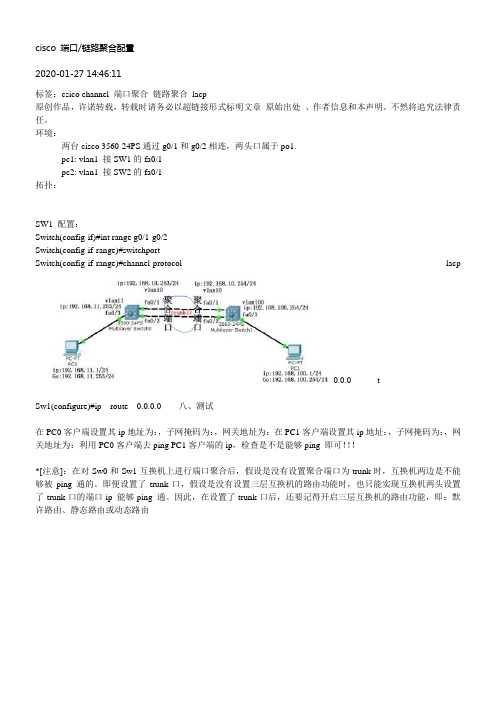
两台cisco 3560-24PS通过g0/1和g0/2相连,两头口属于po1.
pc1: vlan1 接SW1的fa0/1
pc2: vlan1 接SW2的fa0/1
拓扑:
SW1 配置:
Switch(config-if)#int range g0/1-g0/2
Switch(config-if-range)#switchport
Switch(config-if-range)#channel-protocol lacp
0.0.0 t
Sw1(configure)#ip route 0.0.0.0 八、测试
在PC0客户端设置其ip地址为:,子网掩码为:,网关地址为:在PC1客户端设置其ip地址:,子网掩码为:,网关地址为:利用PC0客户端去ping PC1客户端的ip,检查是不是能够ping 即可!!!
*[注意]:在对Sw0和Sw1互换机上进行端口聚合后,假设是没有设置聚合端口为trunk时,互换机两边是不能够被ping 通的。
即便设置了trunk口,假设是没有设置三层互换机的路由功能时,也只能实现互换机两头设置了trunk口的端口ip 能够ping 通。
因此,在设置了trunk口后,还要记得开启三层互换机的路由功能,即:默许路由、静态路由或动态路由。
三层交换机链路聚合 [Cisco三层交换机链路聚合配置应用实例]
![三层交换机链路聚合 [Cisco三层交换机链路聚合配置应用实例]](https://img.taocdn.com/s3/m/b6986b6a77232f60dccca128.png)
竭诚为您提供优质的服务,优质的文档,谢谢阅读/双击去除三层交换机链路聚合 [Cisco三层交换机链路聚合配置应用实例]交换机是计算机网络的基础核心设备,因此有效的管理好交换机是解决网络安全以及可靠性的关键。
接下来是小编为大家收集的cisco三层交换机链路聚合配置应用实例方法,希望能帮到大家。
cisco三层交换机链路聚合配置应用实例的方法交换机连接拓扑图如下:步骤:一、两台三层交换机上创建vlan:sw0#conftsw0(configure)#vlan10sw0(configure-vlan)#exitsw0(configure)#vlan11sw0(configure-vlan)#exit二、在sw0交换机上将端口fa0/1-2加入到vlan10中,端口fa0/3加入到vlan11中sw0(configure)#intrangefa0/1-2sw0(configure-if-range)#switchportaccessvlan10 sw0(configure-if-range)#exitsw0(configure)#intfa0/3sw0(configure-if)#switchportaccessvlan11sw0(configure)#exit三、在sw1交换机上将fa0/1-2号端口加入到vlan10中,将fa0/3号端口加到vlan100中sw1#conftsw1(configure)#intrangefa0/1-2sw1(configure-if-range)#switchportaccessvlan10 sw1(configure-if-range)#exitsw1(configure)#intfa0/3sw1(configure-if)#switchportaccessvlan100sw1(configure-if)#exit四、在sw0和sw1交换机上为每个vlan配置虚拟ip地址sw0#conftsw0(configure)#intvlan10sw0(configure-if-vlan)#ipaddress192.168.10.253255.2 55.255.0sw0(configure-if-vlan)#noshutdownsw0(configure-if-vlan)#exitsw0(configure)#intvlan11sw0(configure-if-vlan)#ipaddresss192.168.11.254255. 255.255.0sw0(configure-if-vlan)#noshutdownsw0(configure-if-vlan)#exitsw1#conftsw1(configure)#intvlan10sw1(configure-if-vlan)#ipaddress192.168.10.254255.2 55.255.0sw1(configure-if-vlan)#noshutdownsw1(configure-if-vlan)#exitsw1(configure)#intvlan100sw1(configure-if-vlan)#ipaddress192.168.100.254255. 255.255.0sw1(configure-if-vlan)#noshutdownsw1(configure-if-vlan)#exit五、将sw0和sw1交换机相连的fa0/1-2口进行聚合sw0#conftsw0(configure)#intrangefa0/1-2sw0(configure-if-range)#channel-group1modedesirable sw0(configure-if-range)#exitsw1#conftsw1(configure)#intrangefa0/1-2sw1(configure-if-range)#channel-gropu1modedesirablesw1(configure-if-range)#exit【可选做】//六、在sw0和sw1交换机上将聚合端口设置为trunk口sw0#conftsw0(configure)#intport-channel1sw0(configure-if)#switchportmodetrunksw0(configure-if)#switchporttrunknativevlan10 sw0(configure-if)#exitsw1#conftsw1(configure)#intport-channel1sw1(configure-if)#switchportmodetrunksw1(configure-if)#switchporttrunknativevlan10 sw1(configure-if)#exit//七、在sw0和sw1交换机上设置默认路由(当然你也可以设置能实现路由功能的协议)sw0#conftsw0(configure)#iproute0.0.0.00.0.0.0192.168.10.254sw0(configure)#exitsw1#conftsw1(configure)#iproute0.0.0.00.0.0.0192.168.10.253sw1(configure)#exit八、测试在pc0客户端设置其ip地址为:192.168.11.1,子网掩码为:255.255.255.0,网关地址为:192.168.11.254在pc1客户端设置其ip地址:192.168.100.1,子网掩码为:255.255.255.0,网关地址为:192.168.100.254利用pc0客户端去pingpc1客户端的ip,检查是否能够ping即可*[注意]:在对sw0和sw1交换机上进行端口聚合后,如果没有设置聚合端口为trunk时,交换机两边是不能够被ping通的。
cisco交换机端口聚合口怎么配置

cisco交换机端口聚合口怎么配置交换机的主要功能包括物理编址、网络拓扑结构、错误校验、帧序列以及流控。
交换机还具备了一些新的功能,如对VLAN(虚拟局域网)的支持、对链路汇聚的支持,甚至有的还具有防火墙的功能。
其中聚合口通过一些配置,能有效提高交换机端口速率,具体怎么设置呢?下面我们一起来看看方法步骤1、打开cisco模拟器---选择交换机s2960、直连线、服务器像如图连接起来。
2、选择交换机switch0进行配置----进入特权模式,将fa0/1和fa0/2端口模式配置成trunk。
3、将fa0/1和fa0/2加入链路组1并开启----按照目标主机地址IP数据分发来实现负荷平衡----通过show etherchannel summary来查看聚合口配置情况。
4、按照交换机switch0的配置,配置switch1----可以看到刚才block的端口变绿,表示已经开通。
5、将pc0 IP配置为192.168.1.2子网掩码为255.255.255.0,pc1 IP配置为192.168.1.3子网掩码为255.255.255.0---pc0 ping pc1,pc1 ping pc0都可以ping通,即完成聚合口的配置。
补充:交换机基本使用方法作为基本核心交换机使用,连接多个有线设备使用:网络结构如下图,基本连接参考上面的【方法/步骤1:基本连接方式】作为网络隔离使用:对于一些功能好的交换机,可以通过模式选择开关选择网络隔离模式,实现网络隔离的作用,可以只允许普通端口和UPlink端口通讯,普通端口之间是相互隔离不可以通讯的除了作为核心交换机(中心交换机)使用,还可以作为扩展交换机(接入交换机)来扩展网络放在路由器上方,扩展网络供应商的网络线路(用于一条线路多个IP的网络),连接之后不同的路由器用不同的IP连接至公网相关阅读:交换机硬件故障常见问题电源故障:由于外部供电不稳定,或者电源线路老化或者雷击等原因导致电源损坏或者风扇停止,从而不能正常工作。
- 1、下载文档前请自行甄别文档内容的完整性,平台不提供额外的编辑、内容补充、找答案等附加服务。
- 2、"仅部分预览"的文档,不可在线预览部分如存在完整性等问题,可反馈申请退款(可完整预览的文档不适用该条件!)。
- 3、如文档侵犯您的权益,请联系客服反馈,我们会尽快为您处理(人工客服工作时间:9:00-18:30)。
cisco 端口/链路聚合配置
2011-01-27 14:46:11
标签:csico channel 端口聚合链路聚合lacp
原创作品,允许转载,转载时请务必以超链接形式标明文章原始出处、作者信息和本声明。
否则将追究法律责任。
/715953/486648
环境:
两台cisco 3560-24PS通过g0/1和g0/2相连,两端口属于po1.
pc1:192.168.1.10 vlan1 接SW1的fa0/1
pc2:192.168.1.11 vlan1 接SW2的fa0/1
拓扑:
SW1 配置:
Switch(config-if)#int range g0/1-g0/2
Switch(config-if-range)#switchport
Switch(config-if-range)#channel-protocol lacp //以太信道使用链路聚合协议协商
Switch(config-if-range)#channel-group 1 mode active //链路聚合加入通道组1,并设置协商模式为active
Switch(config-if-range)#switchport //端口设置为二层端口
Switch(config-if-range)#switchport trunk encapsulation dot1q //中继链路封装格式为dot1q Switch(config-if-range)# swit mode trunk //将
Switch(config-if-range)# swit trunk allow vlan all
SW2配置(与SW1配置类似):
Switch(config-if)#int range g0/1-g0/2
Switch(config-if-range)#switchport
Switch(config-if-range)#channel-protocol lacp
Switch(config-if-range)#channel-group 1 mode passive //链路聚合加入通道组1,并设置协商模式为passive或者on
Switch(config-if-range)#switchport trunk encapsulation dot1q
Switch(config-if-range)# swit mode trunk
Switch(config-if-range)# swit trunk allow vlan all
本文出自“菜鸟·小蜗牛”博客,请务必保留此出处/715953/486648
步骤:
一、两台三层交换机上创建vlan:
Sw0#conf t
Sw0(configure)#vlan 10
Sw0(configure-vlan)#exit
Sw0(configure)#vlan 11
Sw0(configure-vlan)#exit
二、在Sw0交换机上将端口fa0/1-2加入到vlan10中,端口fa0/3加入到vlan 11中
Sw0(configure)#int range fa0/1-2
Sw0(configure-if-range)#switchport access vlan 10
Sw0(configure-if-range)#exit
Sw0(configure)#int fa0/3
Sw0(configure-if)# switchport access vlan 11
Sw0(configure)#exit
三、在Sw1交换机上将fa0/1-2号端口加入到vlan 10中,将fa0/3号端口加到vlan 100中Sw1#conf t
Sw1(configure)#int range fa0/1-2
Sw1(configure-if-range)#switchport access vlan 10
Sw1(configure-if-range)#exit
Sw1(configure)#int fa0/3
Sw1(configure-if)#switchport access vlan 100
Sw1(configure-if)#exit
四、在Sw0和Sw1交换机上为每个vlan 配置虚拟ip地址
Sw0#conf t
Sw0(configure)#int vlan 10
Sw0(configure-if-vlan)#ip address 192.168.10.253 255.255.255.0
Sw0(configure-if-vlan)#no shutdown
Sw0(configure-if-vlan)#exit
Sw0(configure)#int vlan 11
Sw0(configure-if-vlan)#ip addresss 192.168.11.254 255.255.255.0
Sw0(configure-if-vlan)#no shutdown
Sw0(configure-if-vlan)#exit
Sw1#conf t
Sw1(configure)#int vlan 10
Sw1(configure-if-vlan)#ip address 192.168.10.254 255.255.255.0
Sw1(configure-if-vlan)#no shutdown
Sw1(configure-if-vlan)#exit
Sw1(configure)#int vlan 100
Sw1(configure-if-vlan)#ip address 192.168.100.254 255.255.255.0 Sw1(configure-if-vlan)#no shutdown
Sw1(configure-if-vlan)#exit
五、将Sw0和Sw1交换机相连的fa0/1-2口进行聚合
Sw0#conf t
Sw0(configure)#int range fa0/1-2
Sw0(configure-if-range)#channel-group 1 mode desirable
Sw0(configure-if-range)#exit
Sw1#conf t
Sw1(configure)#int range fa0/1-2
Sw1(configure-if-range)#channel-gropu 1 mode desirable
Sw1(configure-if-range)#exit
【可选做】// 六、在Sw0和Sw1交换机上将聚合端口设置为trunk口Sw0#conf t
Sw0(configure)#int port-channel 1
加一句:sw tr en dot1q
Sw0(configure-i)#switchport mode trunk
Sw0(configure-if)#switchport trunk native vlan 10
Sw0(configure-if)#exit
Sw1#conf t
Sw1(configure)#int port-channel 1
Sw1(configure-if)#switchport mode trunk
Sw1(configure-if)#switchport trunk native vlan 10
Sw1(configure-if)#exit
//
七、在Sw0和Sw1交换机上设置默认路由(当然你也可以设置能实现路由功能的协议)
Sw0#conf t
Sw0(configure)#ip route 0.0.0.0 0.0.0.0 192.168.10.254
Sw0(configure)#exit
Sw1#conf t
Sw1(configure)#ip route 0.0.0.0 0.0.0.0 192.168.10.253
Sw1(configure)#exit
八、测试
在PC0客户端设置其ip地址为:192.168.11.1,子网掩码为:255.255.255.0,网关地址为:192.168.11.254
在PC1客户端设置其ip地址:192.168.100.1,子网掩码为:255.255.255.0,网关地址为:192.168.100.254
利用PC0客户端去ping PC1客户端的ip,检查是否能够ping 即可!!!
*[注意]:在对Sw0和Sw1交换机上进行端口聚合后,如果没有设置聚合端口为trunk时,交换机两边是不能够被ping 通的。
即使设置了trunk口,如果没有设置三层交换机的路由功能时,也只能实现交换机两端设置了trunk口的端口ip 能够ping 通。
所以,在设置了trunk 口后,还要记得开启三层交换机的路由功能,即:默认路由、静态路由或动态路由
/fy_928/blog/static/116827048200992375121205/。
