实验5 vlan间路由
实验五交换机VLAN配置实验
实验五交换机VLAN配置实验一、实验目的掌握虚拟局域网VLAN的概念和作用,学会在交换机进行单交换机VLAN 配置和跨交换机VLA N配置方法。
二、实验原理与实验内容本次实验分两部分,第一部分是单交换机VLAN配置实验,第二部分是跨交换机VLAN配置实验。
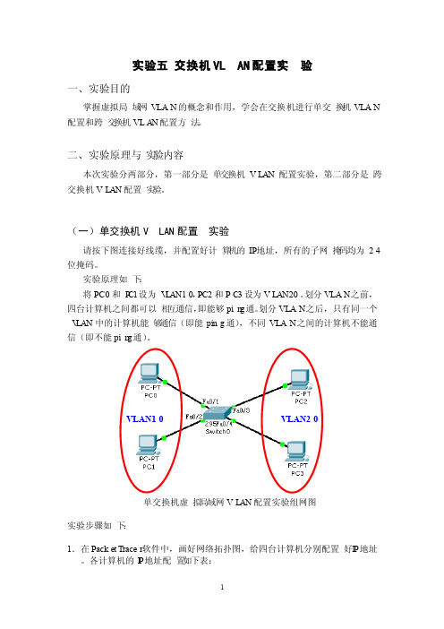
(一)单交换机VLAN配置实验请按下图连接好线缆,并配置好计算机的IP地址,所有的子网掩码均为24位掩码。
实验原理如下:将PC0和P C1设为V L AN10,PC2和PC3设为VLAN20。
划分VLAN之前,四台计算机之间都可以相互通信,即能够pin g通。
划分VLAN之后,只有同一个V LAN中的计算机能够通信(即能ping通),不同VLAN之间的计算机不能通信(即不能pin g通)。
VLAN10VLAN20单交换机虚拟局域网VL AN配置实验组网图实验步骤如下:1.在Packet Tracer软件中,画好网络拓扑图,给四台计算机分别配置好I P地址。
各计算机的I P地址配置如下表:2.在四台计算机上分别使用ping命令,确认它们之间全部能够相互通信。
3.将PC0和P C1设为V L AN10,PC2和PC3设为VL AN20。
在交换机上划分两个VLAN的命令配置如下:Switch>enable//使用enable命令从用户模式进入特权模式Switch#config ure termin al //进入全局配置模式Enterconfig urati on comman ds, one per line. End with CNTL/Z.Switch(config)# //全局配置模式标示符为S witch(config)#在交换机上创建vlan 10和vla n 20两个vl an:Switch(config)#vlan 10 //创建vlan 10Switch(config-vlan)#name vlan10//将其命名为v l an10Switch(config-vlan)#exit //退回到上一级模式Switch(config)#vlan 20 //创建vlan 20Switch(config-vlan)#name vlan20//将其命名为v l an20Switch(config-vlan)#exit //退回到上一级模式将交换机的f0/1~f0/4端口分别划分到两个V L AN中的命令配置如下:Switch(config)#interf ace FastEt herne t0/1 //进入端口f0/1的配置模式Switch(config-if)#switch portmode access//设置端口模式为acce ss类型Switch(config-if)#switch portaccess vlan 10 //将端口f0/1划分到vl an 10中Switch(config-if)#exitSwitch(config)#interf ace FastEt herne t0/2Switch(config-if)#switch portmode accessSwitch(config-if)#switch portaccess vlan 10Switch(config-if)#exitSwitch(config)#interf ace FastEt herne t0/3Switch(config-if)#switch portmode accessSwitch(config-if)#switch portaccess vlan 20Switch(config-if)#exitSwitch(config)#interf ace FastEt herne t0/4Switch(config-if)#switch portmode accessSwitch(config-if)#switch portaccess vlan 20Switch(config-if)#exit4.测试同一个V LAN之间的计算机能否通信(即能否pin g通),不同的VLA N之间的计算机能否通信(即能否pin g通)。
试验:VLAN间路由

VLAN间路由1 实验目的:配置VLAN间路由。
2 网络拓扑3 试验环境:PC0在交换机Fa0/1端口连接。
PC1在交换机Fa0/2端口连接。
IP地址已经如图配置好。
路由器Fa0/0已经和交换机Fa0/10连接,交换机的Fa0/10处于VLAN 1中。
路由器Fa1/0已经和交换机Fa0/4连接,交换机的Fa0/4处于VLAN 2中。
4 试验要求配置路由器F0/0端口,使其使用Ip地址192.168.0.1 255.255.255.0配置路由器F1/0端口,使其使用Ip地址192.168.1.1 255.255.255.0将PC1的IP地址配制成192.168.1.2 255.255.255.0 网关设置成192.168.1.15 基本配置步骤5.1在PC1上因为不同的VLAN,要使用不同网段的IP地址。
5.2在Router0上Router>enRouter#confi tRouter(config)#int fastEthernet 0/0Router(config-if)#ip address 192.168.0.1 255.255.255.0 Router(config-if)#no shRouter(config-if)#int f1/0Router(config-if)#ip addRouter(config-if)#ip address 192.168.1.1 255.255.255.0 Router(config-if)#no sh5.3在PC1上ping PC 0PC>ping 192.168.0.2Pinging 192.168.0.2 with 32 bytes of data:Request timed out.Reply from 192.168.0.2: bytes=32 time=16ms TTL=127 Reply from 192.168.0.2: bytes=32 time=16ms TTL=127 Reply from 192.168.0.2: bytes=32 time=17ms TTL=127 Ping statistics for 192.168.0.2:Packets: Sent = 4, Received = 3, Lost = 1 (25% loss), Approximate round trip times in milli-seconds:Minimum = 16ms, Maximum = 17ms, Average = 16ms PC>可以看到不同VLAN之间通信必须通过路由器才行。
三层交换机实现VLAN间路由实验(1)
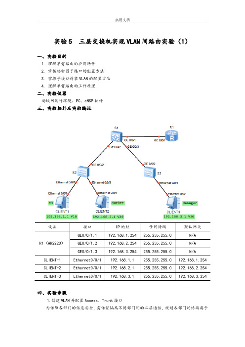
实验5 三层交换机实现VLAN间路由实验(1)一、实验目的1. 理解单臂路由的应用场景2. 掌握路由器子接口的配置方法3. 掌握子接口封装VLAN的配置方法4. 理解单臂路由的工作原理二、实验仪器局域网运行环境、PC、eNSP软件三、实验拓扑及实验编址四、实验步骤1.创建VLAN并配置Access、Trunk接口为保障各部门的信息安全,需保证隔离不同部门间的二层通信,规划各部门的终端属于不同的VLAN ,并为PC 配置相应的IP 地址。
在S2上创建VLAN10和VLAN20,把连接CLIENT-1的E0/0/1和连接CLIENT-2的E0/0/2接口配置为Access 类型接口,并分别划分到相应的VLAN 中。
截图操作结果:在S3上创建VLAN30,把连接CLIENT-3的E0/0/1接口配置为Access 类型接口,并划分到VLAN30。
截图操作结果:交换机之间或交换机和路由器之间连接的接口需要传递多个VLAN 信息,需要配置成Trunk 接口。
将S2和S3的GE0/0/2接口配置成Trunk 类型接口,并允许所有VLAN 通过。
截图操作结果:在S1上创建VLAN10、VLAN20和VLAN30,并配置交换机和路由器相连的接口为Trunk ,允许所有VLAN 通过。
截图操作结果:2.配置路由器子接口和IP 地址由于路由器R1只有一个实际的物理接口与交换机S1相连,可以在路由器上配置不同的逻辑子接口来作为不同VLAN 的网关,从而达到节省路由器接口的目的。
在R1上创建子接口GE0/0/1.1,配置IP 地址192.168.1.254/24,作为人事部网关地址。
(子接口一般配置在路由器上, 当一个物理接口需要配置多个IP 网段时,使用。
)命令行格式:[R1]interface GigabitEthernet0/0/1.1[R1-GigabitEthernet0/0/1.1]ip address 192.168.1.254 24S2 S3S1在R1上创建子接口GE0/0/1.2,配置IP地址192.168.2.254/24,作为市场部网关地址。
VLAN间路由配置心得体会

VLAN间路由配置心得体会第一篇:VLAN间路由配置心得体会VLAN间路由配置心得体会众所周知,第二层平面网络的扩展性不佳,各站点发送数据包前要广播查询目的地的MAC地址。
由于大量应用层软件需要广播传送某些数据包,而这些数据广播包只需发向某一组用户,如果此时没有VLAN(Virtual Local Area Network),这些数据包会占用大量网络资源,使正常数据包无法获得带宽,从而严重影响网络效率及性能。
VLAN依靠用户的逻辑设定将原来物理上互联的一个局域网络划分为多个虚拟网段,即在两层交换机的逻辑上划分若干LAN(广播域),将广播信息、组播信息等限制在特定的一组端口上,从而为限制全网范围的广播和多点广播提供有效手段。
在网络设计中,应选择切实可行的技术进行VLAN的灵活划分。
划分可依据设备所连的端口、用户节点的MAC地址等,划分的结果是使同一个VLAN内的数据可自由通信。
不同VLAN间的数据交流需要通过第三层交换完成。
即通过跨越交换机划分VLAN,从而高性能地实现VLAN之间的路由,提高带宽利用率和网络性能,增强网络应用的灵活性和安全性。
二、VLAN在网络中的典型划分VLAN在网络中的典型划分如图1所示。
VLAN通常与IP网络是相关联的,例如特定IP子网中的所有工作端属于同一个VLAN,不同VLAN之间必须通过路由器或具有路由器功能的模块才能通信。
VLAN可以是动态的,也可以是静态的。
所谓动态VLAN就是基于工作站的MAC地址,即根据工作站上网卡的48位硬件地址划分的VLAN。
动态VLAN主要是通过每台交换机所连接工作站的MAC地址,它将一组MAC地址划分在同一逻辑组中,其中的成员不会因地理位置的改变而改变(这种方法仅用于局域网)。
静态VLAN是一种具有固定地理位置的划分方法,它基于交换机端口的划分,可以通过对交换机的适当设置,将同一个交换机或不同交换机上的一组端口划分在同一个VLAN中。
VTP(VLAN Trunk Protocol)协议主要用于多台局域网交换机互联情况下有效管理VLAN的配置。
实验五端口聚合及基本Vlan设置
实验五交换机端口聚合及基本Vlan设置一、实验目的了解端口聚合的基本概念和方式;了解Vlan的基本配置二、华为模拟器HW-RouteSim介绍Hw-routesim 是华为系列设备的模拟器,采用图形工作视窗,网络拓扑结构清晰明了,直接单击即可进入配置命令状态,使用简单,包括路由器,交换机,计算机等设备的基本配置方法。
三、VLAN介绍VLAN(Virtual Local Area Network)的中文名为"虚拟局域网"。
VLAN是一种将局域网设备从逻辑上划分成一个个网段,从而实现虚拟工作组的新兴数据交换技术。
这一新兴技术主要应用于交换机和路由器中,但主流应用还是在交换机之中。
但又不是所有交换机都具有此功能,只有VLAN协议的第二层以上交换机才具有此功能。
四、常用的配置1)PC机的配置login:root #默认登陆用户名password:linux #默认登陆密码[root@PCA root]#ifconfig eth0 192.168.221.2 netmask 255.255.0.0#为pc机配置IP[root@PCA root]#route add default gw 192.168.221.1 #给PC机配置网关2)交换机的配置<Quidway>system[Quidway]sysname switch #交换机命名[switch]super password simple 111 #设置特权密码[switch]vlan 2[switch-vlan2]port ethernet0/2 #单个端口添加到VLAN[switch-vlan2]port e0/4 to et0/6 #集体添加端口[switch]interface vlan 1[switch-Vlan-interface1]ip address 10.65.1.8 255.255.0.0 #给VLAN配置IP地址3)路由器基本配置<Quidwqy>system[Quidway]sysname router #路由器命名[router]super password simple 111 #设置特权密码[router]interface ethernet0/0[router]interface s0/0[router-Ethernet0/0]ip addr 192.168.221.1 255.255.255.0 #为端口e0/0配置IP地址[router-Ethernet0/0]undo shutdown #激活端口五、端口聚合1)实验拓扑2)实验要求要求聚合的端口工作在全双工,速度一致,在同一槽口且连续。
实验五:VLAN间路由

实验五:VLAN间路由配置
⏹实验目的
1、掌握单臂路由的工作原理
2、学习配置单臂路由的命令和步骤
⏹实验要求
1、拓扑与地址规划;
2、单臂路由基本配置
3、验证连通性,并给出配置清单
⏹实验拓扑(可选)
⏹实验设备(环境、软件)
路由器1台,交换机1台,直通线3条,Pc机2台。
⏹实验设计到的基本概念和理论
给出单臂路由的基本概念
⏹实验过程和主要步骤
1、绘制网络拓扑和地址规划
2、路由器上面的配置
3、路由器上单臂路由的配置
4、验证2个PC配置状况PC0:
PC1:
5.在PC机上验证用PC0pingPC1:
心得体会
通过本次实验学生最终获得的什么如果出现问题,是什么问题是怎么解决的是通过什么方式、通过什么人来帮忙解决的等等。
实验五利用三层交换机实现VLAN间路由

实验五利用三层交换机实现VLAN间路由实验五利用三层交换机实现VLAN间路由一、实验目的1.掌握交换机Tag vlan配置方法2.掌握三层交换机基本配置方法。
3.掌握三层交换机VLAN路由的配置方法4.通过三层交换机实现VLAN间互相通信二、实验环境S2126(1台)、S3550(1台)、主机(3台)、直连线(4条)、交叉线(1条)。
三、实验背景某企业有两个主要部门,技术部和销售部,分处于不同的办公室,为了安全和便于管理对两个部门的主机进行了VLAN的划分,技术部和销售部分处于不同的VLAN,现由于业务的需求需要销售部和技术部的主机能够互相访问,获得相应的资源,两个部门的交换机通过一台三层交换机进行了连接。
四、技术原理三层交换机具备网络层的功能,实现VLAN互相访问的原理是:利用三层交换机的路由功能,通过识别数据包的IP地址,查找路由表进行选路转发,三层交换机利用其直接路由可以实现不同VLAN之间的互相访问。
三层交换机给接口配置IP 地址,采用SVI(交换虚拟接口)的方式实现VLAN间互联,SVI是指为交换机中的VLAN创建虚拟接口,并且配置IP地址。
五、实验步骤1、新建拓扑图2、在二层交换机上配置VLAN2、VLAN3,分别将端口2、端口3划分到VLAN2、VLAN3中。
3、将二层交换机和三层交换机相连接的端口都定义为Tag vlan模式。
4、在三层交换机上配置VLAN2、VLAN3,此时验证二层交换机(VLAN2、VLAN3)下两主机之间不能互相通信。
5、设置三层交换机VLAN间通信,创建VLAN2、VLAN3的虚拟接口,并配置虚拟接口的IP地址。
6、查看三层交换机路由表7、将二层交换机VLAN2、VLAN3下的主机默认网关分别设置为相应虚拟接口的IP地址。
8、验证二层交换机(VLAN2、VLAN3)下两主机之间可以互相通信。
六、实验过程中需要的相关知识点1、创建、修改一个VLAN在特权模式下,通过如下步骤,您可以创建或者修改一个VLAN:命令含义步骤1 configure terminal进入全局配置模式步骤2 vlan vlan-id 输入一个VLAN ID。
实验:VLAN之间的路由设置
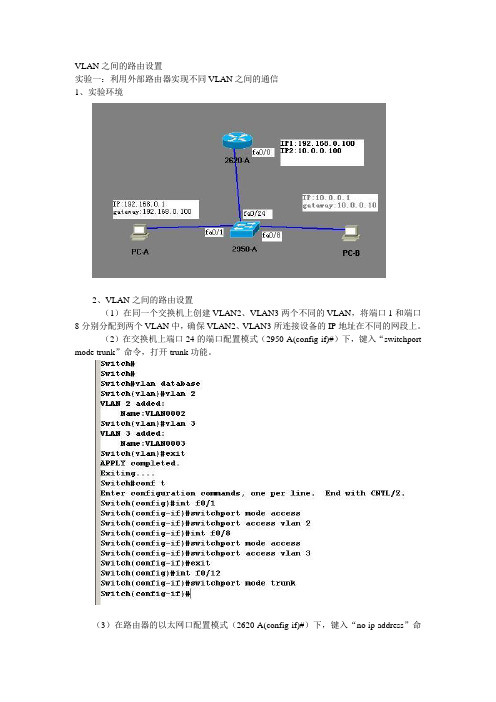
VLAN之间的路由设置实验一:利用外部路由器实现不同VLAN之间的通信1、实验环境2、VLAN之间的路由设置(1)在同一个交换机上创建VLAN2、VLAN3两个不同的VLAN,将端口1和端口8分别分配到两个VLAN中,确保VLAN2、VLAN3所连接设备的IP地址在不同的网段上。
(2)在交换机上端口24的端口配置模式(2950-A(config-if)#)下,键入“switchport mode trunk”命令,打开trunk功能。
(3)在路由器的以太网口配置模式(2620-A(config-if)#)下,键入“no ip address”命令,删除原来的地址。
(4)键入“interface fastethernet 0/0.1”,划分子端口1。
键入“encapsulation dot1q 2”,封装dot1q协议,这里的2对应着VLAN号2(即VLAN 2)。
键入“ip address 192.168.0.100 255.255.255.0”,确保IP地址与VLAN 2所连接设备的IP地址在同一个网段。
(5)键入“interface fastethernet 0/0.2”,划分子端口2。
键入“encapsulation dot1q 3”,封装dot1q协议,这里的3对应着VLAN号2(即VLAN 3)。
键入“ip address 10.0.0.100 255.0.0.0”,确保IP地址与VLAN 3所连接设备的IP地址在同一个网段。
(Config)#int f0/0(Config-if)#full-dupl(Config-if)#no shundown ,用来激活该子端口(6)分别在VLAN2、VLAN3内所连的计算机上设置缺省网关。
(7)利用ping命令测试计算机的通讯情况。
(8)在交换机的VLAN配置模式(2950-A(vlan)#)下,键入“no vlan 2”、“no vlan 3”命令,删除VLAN。
IP通信实验报告——VLAN间路由

IP通信基础实验报告VLAN间路由实验一、实验目的掌握三层交换机静态路由的配置方法二、实验内容(仿真程序‘静态路由switcher.pkt’)三层交换机静态路由的配置三、实验设备三层交换机 3台PC机 2台交叉网线 2条直通网线 2条四、实验拓扑图五、配置步骤====底层配置RS1Switch>enableSwitch#configure terminalEnter configuration commands, one per line. End with CNTL/Z.Switch(config)#hostname RS1RS1(config)#vlan 10RS1(config-vlan)#exitRS1(config)#vlan 12RS1(config-vlan)#exitRS1(config)#interface fastEthernet 0/1RS1(config-if)#no shutdownRS1(config-if)#switchport mode accessRS1(config-if)#switchport access vlan 10RS1(config-if)#exitRS1(config)#interface vlan 10%LINK-5-CHANGED: Interface Vlan10, changed state to up%LINEPROTO-5-UPDOWN: Line protocol on Interface Vlan10, changed state to upRS1(config-if)#ip address 192.168.10.254 255.255.255.0 RS1(config-if)#exitRS1(config)#interface fastEthernet 0/10RS1(config-if)#no shutdownRS1(config-if)#switchport mode accessRS1(config-if)#switchport access vlan 12RS1(config-if)#exitRS1(config)#interface vlan 12%LINK-5-CHANGED: Interface Vlan12, changed state to up%LINEPROTO-5-UPDOWN: Line protocol on Interface Vlan12, changed state to upRS1(config-if)#no shutdownRS1(config-if)#ip address 12.12.12.1 255.255.255.0RS1(config-if)#exitRS1(config)#RS2=================================================== ===========Switch>enableSwitch#configure terminalEnter configuration commands, one per line. End with CNTL/Z.Switch(config)#hostname RS2RS2(config)#vlan 12RS2(config-vlan)#exitRS2(config)#vlan 23RS2(config-vlan)#exitRS2(config)#interface fastEthernet 0/10RS2(config-if)#no shutdownRS2(config-if)#switchport mode accessRS2(config-if)#switchport access vlan 12RS2(config-if)#exitRS2(config)#interface vlan12%LINK-5-CHANGED: Interface Vlan12, changed state to up%LINEPROTO-5-UPDOWN: Line protocol on Interface Vlan12, changed state to upRS2(config-if)#no shutdownRS2(config-if)#ip address 12.12.12.2 255.255.255.0RS2(config-if)#exitRS2(config)#interface fastEthernet 0/20RS2(config-if)#no shutdownRS2(config-if)#switchport mode accessRS2(config-if)#switchport access vlan 23RS2(config-if)#exitRS2(config)#interface vlan23RS2(config-if)#%LINK-5-CHANGED: Interface Vlan23, changed state to up%LINEPROTO-5-UPDOWN: Line protocol on Interface Vlan23, changed state to upRS2(config-if)#no shutdownRS2(config-if)#ip address 23.23.23.2 255.255.255.0RS2(config-if)#exitRS2(config)#RS3=================================================== ==============Switch>enableSwitch#configure terminalEnter configuration commands, one per line. End with CNTL/Z.Switch(config)#hostname RS3RS3(config)#vlan 23RS3(config-vlan)#exitRS3(config)#vlan 20RS3(config-vlan)#exitRS3(config)#interface fastEthernet 0/20RS3(config-if)#no shutdownRS3(config-if)#switchport mode accessRS3(config-if)#switchport access vlan 23RS3(config-if)#exitRS3(config)#interface vlan 23%LINK-5-CHANGED: Interface Vlan23, changed state to up%LINEPROTO-5-UPDOWN: Line protocol on Interface Vlan23, changed state to upRS3(config-if)#no shutdownRS3(config-if)#ip address 23.23.23.1 255.255.255.0RS3(config-if)#exitRS3(config)#interface fastEthernet 0/1RS3(config-if)#no shutdownRS3(config-if)#switchport mode accessRS3(config-if)#switchport access vlan 20RS3(config-if)#exitRS3(config)#interface vlan20%LINK-5-CHANGED: Interface Vlan20, changed state to up%LINEPROTO-5-UPDOWN: Line protocol on Interface Vlan20, changed state to upRS3(config-if)#no shutdownRS3(config-if)#ip address 192.168.20.254 255.255.255.0 RS3(config-if)#exitRS3(config)#====静态路由配置RS1RS1(config)#ip route 192.168.20.0 255.255.255.0 12.12.12.2RS1(config)#ip route 23.23.23.0 255.255.255.0 12.12.12.2RS2RS2(config)#ip route 192.168.20.0 255.255.255.0 23.23.23.1RS2(config)#ip route 192.168.10.0 255.255.255.0 12.12.12.1RS3RS3(config)#ip route 192.168.10.0 255.255.255.0 23.23.23.2RS3(config)#ip route 12.12.12.0 255.255.255.0 23.23.23.2 六、验证方法及验证结果sw2#show ip route %可以查看路由表验证结果如下:七、实验结论路由器能够通过配置,学习到网络的路由信息,创建路由表。
实训名称:基于路由器物理接口的vlan间路由

实训名称:基于路由器物理接口的vlan间路由一、实训原理1、二层没有网关,必需借助三层设备,才能使不同的vlan之间实现通信。
二、实训目的1、两个vlan之间实现通信三、实训内容对于处于不同交换机但是属于同一个vlan的客户机进行配置。
添加路由器,并在路由器的物理接口上配置vlan的网关。
四、实训步骤:1、配左边的交换机2、配右边的交换机3、配置路由器4、再配PC机IP地址拓扑图具体步骤:左边的交换机EnConfVlan 2Name jsbExitVlan 3Name xsbExitInt f0/2switchport mode access switchport access vlan 2 int f0/3switchport mode access switchport access vlan 3 int f0/1switchport mode trunk Int f0/4switchport mode access switchport access vlan 2 int f0/5switchport mode access switchport access vlan 3右边的交换机EnConfVlan 2Name jsbExitVlan 3Name xsbExitInt f0/2switchport mode accessswitchport access vlan 2int f0/3switchport mode accessswitchport access vlan 3int f0/1switchport mode trunk配置路由器EnConfInt f0/0Ip add 192.168.2.254 255.255.255.0No shutInt f0/1Ip add 192.168.3.254 255.255.255.0No shut给PC机配置IP地址PC0:192.168.3.1/24,网关:192.168.3.254 PC2:192.168.3.2/24,网关:192.168.3.254 PC1:192.168.2.1/24,网关:192.168.2.254 PC3:192.168.2.2/24,网关:192.168.2.254 五、实训结果1、在PC0下ping PC2 的IP地址2、在PC1下ping PC3 的IP地址3、PC0 ping PC1。
VLAN间的路由配置实验报告

“计算机网络实验”-实验报告实验序号:实验项目名称:VLAN之间的路由配置实验台号:三实验组号:实验时间:5月15日8:00—16:15实验成员及分工:实验目的:实验1,熟悉交换机的命令,掌握交换机的配置,学会如何划分vlan 子网。
实验2,进一步熟悉各个设备的配置,同时掌握路由控制链表的配置。
实验设备和环境:设备:两台pc,两台路由器,一台3750交换机,两台2950交换机,若干设备连接线环境:安全的网络环境实验过程及步骤:(可以另附页,给出相应的实验环境拓扑图和实验说明)实验总结:(遇到的问题、解决方法、收获和体会,可以另附页)实验器材、验收同学:实验责任人:实验记录人:报告执笔人:实验完成时间:验收同学:实验小组成员签名:指导教师签名: 成绩:一、VLAN 之间的路由配置Switch>enable Switch#config tEnter configuration commands, one per line. End with CNTL/Z. Switch(config)#hostname c3750 c3750(config)#exit c3750#00:01:19: %SYS-5-CONFIG_I: Configured from console by console c3750#vlan b00:01:25: %LINEPROTO-5-UPDOWN: Line protocol on Interface Vlan1, changed state t o upc3750#vlan basedata ^% Invalid input detected at '^' marker.c3750#vlan database% Warning: It is recommended to configure VLAN from config mode, as VLAN database mode is being deprecated. Please consult user documentation for configuring VTP/VLAN in config mode.c3750(vlan)#vlan 2 name market交换机3750IP 地址: 192.168.2.2 默认网关: 192.168.2.1交换机2950IP 地址: 192.168.3.5 默认网关: 192.168.3.1路由器2811fa1/0/24fa1/0/23fa0/24fa 0/0图9.5 采用单臂路由实现VLAN 之间的路由VLAN 2 modified:Name: marketc3750(vlan)#vlan 3 name developVLAN 3 modified:Name: developc3750(vlan)#end^% Invalid input detected at '^' marker.c3750(vlan)#exitAPPL Y completed.Exiting....c3750#config tEnter configuration commands, one per line. End with CNTL/Z.c3750(config)#inter range f0/1 -4^% Invalid input detected at '^' marker.c3750(config)#inter range f1/1 -4^% Invalid input detected at '^' marker.c3750(config)#inter range fa1/1 -4^% Invalid input detected at '^' marker.c3750(config)#interface range fa1/0/1 -4c3750(config-if-range)#switchport access vlan 2c3750(config-if-range)#interface range fa1/0/5 -8c3750(config-if-range)#switchport access vlan 3c3750(config-if-range)#exitc3750(config)#inter fa1/0/24c3750(config-if)#switchport trunk encap dot1qc3750(config-if)#switchport mode trunkc3750(config-if)#interface fa1/0/23c3750(config-if)#switchport tunk encap dot1q^% Invalid input detected at '^' marker.c3750(config-if)#switchport trunk encap dot1qc3750(config-if)#switchport mode trunkc3750(config-if)#e00:07:57: %LINEPROTO-5-UPDOWN: Line protocol on Interface FastEthernet1/0/23, changed state to downc3750(config-if)#exitc3750(config)#00:08:00: %LINEPROTO-5-UPDOWN: Line protocol on Interface FastEthernet1/0/23, changed state to upc3750(config)#% Please answer 'yes' or 'no'.Would you like to enter the initial configuration dialog? [yes/no]:% Please answer 'yes' or 'no'.Would you like to enter the initial configuration dialog? [yes/no]: noPress RETURN to get started!Router>Router>enableRouter#config tEnter configuration commands, one per line. End with CNTL/Z.Router(config)#inter f0/0Router(config-if)#no shutdownRouter(config-if)#Router(config-if)#*May 15 03:16:07.219: %LINK-3-UPDOWN: Interface FastEthernet0/0, changed state to up*May 15 03:16:10.219: %LINEPROTO-5-UPDOWN: Line protocol on Interface FastEthernet0/0, changed state to upRouter(config-if)#interf f0/0.2Router(config-subif)#encap dot1q 2Router(config-subif)#ip address% Incomplete command.Router(config-subif)#ip address 192.168.2.1 255.255.255.0Router(config-subif)#no shutdownRouter(config-subif)#inter f0/0.3Router(config-subif)#encap dot1q 3Router(config-subif)#ip address 192.168..3.1 255.255.255.0^% Invalid input detected at '^' marker.Router(config-subif)#ip address 192.168.3.1 255.255.255.0Router(config-subif)#exitRouter(config)#inter f0/0.3Router(config-subif)#no shutdownRouter(config-subif)#endRouter#*May 15 03:19:17.519: %SYS-5-CONFIG_I: Configured from console by console% Please answer 'yes' or 'no'.Would you like to enter the initial configuration dialog? [yes/no]: nPress RETURN to get started!Switch>00:13:51: %LINK-5-CHANGED: Interface Vlan1, changed state to administratively down00:13:52: %LINEPROTO-5-UPDOWN: Line protocol on Interface Vlan1, changed state to downe% Ambiguous command: "e"Switch>enableSwitch#config tEnter configuration commands, one per line. End with CNTL/Z.Switch(config)#hostname c2950c2950(config)#exitc2950#v00:14:18: %SYS-5-CONFIG_I: Configured from console by console]% Unknown command or computer name, or unable to find computer addressc2950#vlan database% Warning: It is recommended to configure VLAN from config mode,as VLAN database mode is being deprecated. Please consult user documentation for configuring VTP/VLAN in config mode.c2950(vlan)#vlan 2 name marketVLAN 2 modified:Name: marketc2950(vlan)#vlan 3 name developVLAN 3 modified:Name: developc2950(vlan)#vtp clientDevice mode already VTP CLIENT.c2950(vlan)#exitIn CLIENT state, no apply attempted.Exiting....c2950#config tEnter configuration commands, one per line. End with CNTL/Z.c2950(config)#inter range fa0/1 -4c2950(config-if-range)#switchport access vlan 2c2950(config-if-range)#inter range fa0/0/5 -8^% Invalid input detected at '^' marker.c2950(config)#inter range fa0/5 -8c2950(config-if-range)#switchport access vlan 3c2950(config-if-range)#interface f0/24c2950(config-if)#switchport mode trunkc2950(config-if)#exitc2950(config)#endc2950#00:18:36: %SYS-5-CONFIG_I: Configured from console by console二、路由访问控制列表配置未添加acl 之前 R1的配置Router>enable Router#config tEnter configuration commands, one per line. End with CNTL/Z. Router(config)#hostname ri ri(config)#inter f0/0ri(config-if)#ip address 192.168.1.1 255.255.255.0交换机2950-A交换机2950-B路由器r1路由r2IP 地址: 192.168.1.2 默认网关: 192.168.1.1S0/0/0S0/1fa0/1192.168.1.1192.168.2.1fa0/1 192.168.12.2192.168.12.1IP 地址: 192.168.2.2 默认网关: 192.168.2.1图8.20 采用交换机的路由器配置环境ri(config-if)#no shutdown%LINK-5-CHANGED: Interface FastEthernet0/0, changed state to up%LINEPROTO-5-UPDOWN: Line protocol on Interface FastEthernet0/0, changed state to upri(config-if)#inter s0/0/0^% Invalid input detected at '^' marker.ri(config-if)#exitri(config)#inter s0/0/0^% Invalid input detected at '^' marker.ri(config)#inter s0/0/1^% Invalid input detected at '^' marker.ri(config)#inter s0/0ri(config-if)#ri(config-if)#exitri(config)#interface Serial0/0ri(config-if)#ri(config-if)#exitri(config)#interface Serial0/1ri(config-if)#ri(config-if)#exitri(config)#interface Serial0/0ri(config-if)#ip address 192.168.12.1 255.255.255.0ri(config-if)#encap pppri(config-if)#clock rate 64000ri(config-if)#no shutdown%LINK-5-CHANGED: Interface Serial0/0, changed state to downri(config-if)#no shutdownri(config-if)#ri(config-if)#exitri(config)#interface Serial0/0ri(config-if)#exitri(config)#exit%SYS-5-CONFIG_I: Configured from console by consoleri#config tEnter configuration commands, one per line. End with CNTL/Z.ri(config)#router ripri(config-router)#network 192.168.1.0ri(config-router)#network 192.168.12.0ri(config-router)#end%SYS-5-CONFIG_I: Configured from console by consoleri#show ip routeCodes: C - connected, S - static, I - IGRP, R - RIP, M - mobile, B - BGPD - EIGRP, EX - EIGRP external, O - OSPF, IA - OSPF inter areaN1 - OSPF NSSA external type 1, N2 - OSPF NSSA external type 2E1 - OSPF external type 1, E2 - OSPF external type 2, E - EGPi - IS-IS, L1 - IS-IS level-1, L2 - IS-IS level-2, ia - IS-IS inter area* - candidate default, U - per-user static route, o - ODRP - periodic downloaded static routeGateway of last resort is not setC 192.168.1.0/24 is directly connected, FastEthernet0/0ri#%LINK-5-CHANGED: Interface Serial0/0, changed state to upri#show ip routeCodes: C - connected, S - static, I - IGRP, R - RIP, M - mobile, B - BGPD - EIGRP, EX - EIGRP external, O - OSPF, IA - OSPF inter areaN1 - OSPF NSSA external type 1, N2 - OSPF NSSA external type 2E1 - OSPF external type 1, E2 - OSPF external type 2, E - EGPi - IS-IS, L1 - IS-IS level-1, L2 - IS-IS level-2, ia - IS-IS inter area* - candidate default, U - per-user static route, o - ODRP - periodic downloaded static routeGateway of last resort is not setC 192.168.1.0/24 is directly connected, FastEthernet0/0ri#ri#configure terminalEnter configuration commands, one per line. End with CNTL/Z.ri(config)#interface Serial0/0ri(config-if)#ri(config-if)#exitri(config)#ri(config)#ri(config)#router ripri(config-router)#ri#%SYS-5-CONFIG_I: Configured from console by consoleri#ping 192.168.12.1Type escape sequence to abort.Sending 5, 100-byte ICMP Echos to 192.168.12.1, timeout is 2 seconds: .....Success rate is 0 percent (0/5)ri#show interFastEthernet0/0 is up, line protocol is up (connected)Hardware is Lance, address is 00e0.f9aa.eb23 (bia 00e0.f9aa.eb23) Internet address is 192.168.1.1/24MTU 1500 bytes, BW 100000 Kbit, DLY 100 usec,reliability 255/255, txload 1/255, rxload 1/255Encapsulation ARPA, loopback not setARP type: ARPA, ARP Timeout 04:00:00,Last input 00:00:08, output 00:00:05, output hang neverLast clearing of "show interface" counters neverInput queue: 0/75/0 (size/max/drops); Total output drops: 0 Queueing strategy: fifoOutput queue :0/40 (size/max)5 minute input rate 0 bits/sec, 0 packets/sec5 minute output rate 0 bits/sec, 0 packets/sec0 packets input, 0 bytes, 0 no bufferReceived 0 broadcasts, 0 runts, 0 giants, 0 throttles0 input errors, 0 CRC, 0 frame, 0 overrun, 0 ignored, 0 abort0 input packets with dribble condition detected1 packets output, 52 bytes, 0 underruns0 output errors, 0 collisions, 1 interface resets0 babbles, 0 late collision, 0 deferred0 lost carrier, 0 no carrierri#show interFastEthernet0/0 is up, line protocol is up (connected)Hardware is Lance, address is 00e0.f9aa.eb23 (bia 00e0.f9aa.eb23) Internet address is 192.168.1.1/24MTU 1500 bytes, BW 100000 Kbit, DLY 100 usec,reliability 255/255, txload 1/255, rxload 1/255Encapsulation ARPA, loopback not setARP type: ARPA, ARP Timeout 04:00:00,Last input 00:00:08, output 00:00:05, output hang neverLast clearing of "show interface" counters neverInput queue: 0/75/0 (size/max/drops); Total output drops: 0Queueing strategy: fifoOutput queue :0/40 (size/max)5 minute input rate 0 bits/sec, 0 packets/sec5 minute output rate 0 bits/sec, 0 packets/sec0 packets input, 0 bytes, 0 no bufferReceived 0 broadcasts, 0 runts, 0 giants, 0 throttles0 input errors, 0 CRC, 0 frame, 0 overrun, 0 ignored, 0 abort0 input packets with dribble condition detected1 packets output, 52 bytes, 0 underruns0 output errors, 0 collisions, 1 interface resets0 babbles, 0 late collision, 0 deferred0 lost carrier, 0 no carrier0 output buffer failures, 0 output buffers swapped outSerial0/0 is up, line protocol is down (disabled)Hardware is HD64570Internet address is 192.168.12.1/24MTU 1500 bytes, BW 128 Kbit, DLY 20000 usec,reliability 255/255, txload 1/255, rxload 1/255Encapsulation PPP, loopback not set, keepalive set (10 sec)LCP ClosedClosed: LEXCP, BRIDGECP, IPCP, CCP, CDPCP, LLC2, BACPLast input never, output never, output hang neverLast clearing of "show interface" counters never--More--%LINEPROTO-5-UPDOWN: Line protocol on Interface Serial0/0, changed state to upInput queue: 0/75/0 (size/max/drops); Total output drops: 0Queueing strategy: weighted fairOutput queue: 0/1000/64/0 (size/max total/threshold/drops)ri#show ip routeCodes: C - connected, S - static, I - IGRP, R - RIP, M - mobile, B - BGPD - EIGRP, EX - EIGRP external, O - OSPF, IA - OSPF inter areaN1 - OSPF NSSA external type 1, N2 - OSPF NSSA external type 2E1 - OSPF external type 1, E2 - OSPF external type 2, E - EGPi - IS-IS, L1 - IS-IS level-1, L2 - IS-IS level-2, ia - IS-IS inter area* - candidate default, U - per-user static route, o - ODRP - periodic downloaded static routeGateway of last resort is not setC 192.168.1.0/24 is directly connected, FastEthernet0/0R 192.168.2.0/24 [120/1] via 192.168.12.2, 00:00:08, Serial0/0C 192.168.12.0/24 is directly connected, Serial0/0R2的配置Router>enableRouter#hostname r2^% Invalid input detected at '^' marker.Router#config tEnter configuration commands, one per line. End with CNTL/Z.Router(config)#hostname r2r2(config)#interfa f0/0\^% Invalid input detected at '^' marker.r2(config)#inter f0/0r2(config-if)#ip address 192.168.2.1 255.255.255.0r2(config-if)#no shutdown%LINK-5-CHANGED: Interface FastEthernet0/0, changed state to up%LINEPROTO-5-UPDOWN: Line protocol on Interface FastEthernet0/0, changed state to upr2(config-if)#inter s0/1r2(config-if)#ip address 192.168.12.2 255.255.255.0r2(config-if)#no shutdown%LINK-5-CHANGED: Interface Serial0/1, changed state to upr2(config-if)#exitr2(config)#router ripr2(config-router)#network 192.168.12.0r2(config-router)#network 192.168.2.0r2(config-router)#end%SYS-5-CONFIG_I: Configured from console by consoler2#show ip routeCodes: C - connected, S - static, I - IGRP, R - RIP, M - mobile, B - BGPD - EIGRP, EX - EIGRP external, O - OSPF, IA - OSPF inter areaN1 - OSPF NSSA external type 1, N2 - OSPF NSSA external type 2E1 - OSPF external type 1, E2 - OSPF external type 2, E - EGPi - IS-IS, L1 - IS-IS level-1, L2 - IS-IS level-2, ia - IS-IS inter area* - candidate default, U - per-user static route, o - ODRP - periodic downloaded static routeGateway of last resort is not setC 192.168.2.0/24 is directly connected, FastEthernet0/0r2#show ip routeCodes: C - connected, S - static, I - IGRP, R - RIP, M - mobile, B - BGPD - EIGRP, EX - EIGRP external, O - OSPF, IA - OSPF inter areaN1 - OSPF NSSA external type 1, N2 - OSPF NSSA external type 2E1 - OSPF external type 1, E2 - OSPF external type 2, E - EGPi - IS-IS, L1 - IS-IS level-1, L2 - IS-IS level-2, ia - IS-IS inter area* - candidate default, U - per-user static route, o - ODRP - periodic downloaded static routeGateway of last resort is not setC 192.168.2.0/24 is directly connected, FastEthernet0/0r2#conf tEnter configuration commands, one per line. End with CNTL/Z.r2(config)#inter s0/1r2(config-if)#encap pppr2(config-if)#e%LINEPROTO-5-UPDOWN: Line protocol on Interface Serial0/1, changed state to upxitr2(config)#exit%SYS-5-CONFIG_I: Configured from console by consoler2#ping 192.168.12.1Type escape sequence to abort.Sending 5, 100-byte ICMP Echos to 192.168.12.1, timeout is 2 seconds:!!!!!Success rate is 100 percent (5/5), round-trip min/avg/max = 2/3/4 msr2#show ip routeCodes: C - connected, S - static, I - IGRP, R - RIP, M - mobile, B - BGPD - EIGRP, EX - EIGRP external, O - OSPF, IA - OSPF inter areaN1 - OSPF NSSA external type 1, N2 - OSPF NSSA external type 2E1 - OSPF external type 1, E2 - OSPF external type 2, E - EGPi - IS-IS, L1 - IS-IS level-1, L2 - IS-IS level-2, ia - IS-IS inter area* - candidate default, U - per-user static route, o - ODRP - periodic downloaded static routeGateway of last resort is not setR 192.168.1.0/24 [120/1] via 192.168.12.1, 00:00:18, Serial0/1C 192.168.2.0/24 is directly connected, FastEthernet0/0C 192.168.12.0/24 is directly connected, Serial0/1r2#标准数据包过滤ri(config)#access-list 99 deny 192.168.2.2 0.0.0.0ri(config)#access-list permit 0.0.0.0 255.255.255.255^% Invalid input detected at '^' marker.ri(config)#interf s0/0ri(config-if)#ip access-group 99 inri(config-if)#end%SYS-5-CONFIG_I: Configured from console by consoleri#show ip access-listStandard IP access list 99deny host 192.168.2.2ri#扩展ip访问链表配置ri(config)#inter s0/0ri(config-if)#no ip access-group 99 inri(config-if)#exitri(config)#access-list 110 deny tcp 192.168.2.2 0.0.0.0 192.168.12.1.0.0.0.0 eq23^% Invalid input detected at '^' marker.ri(config)#access-list 110 deny tcp 192.168.2.2 0.0.0.0 192.168.12.1.0.0.0.0 eq 23^% Invalid input detected at '^' marker.ri(config)#ri(config)#access-list 110 deny tcp 192.168.2.2 0.0.0.0 192.168.12.1 0.0.0.0 eq 23 ri(config)#inter s0/0ri(config-if)#exitri(config)#access-list 110 permit ip any anyri(config)#inter s0/0ri(config-if)#ip access-group 110 inri(config-if)#exitri(config)#exit%SYS-5-CONFIG_I: Configured from console by console ri#show ip access-listStandard IP access list 99deny host 192.168.2.2Extended IP access list 110deny tcp host 192.168.2.2 host 192.168.12.1 eq telnet permit ip any any (2 match(es))ri#。
Vlan间路由实验(三层交换机实现法)

今天我们来演示VLAN间路由的实验,配置方法有多种,我们首先来演示利用三层交换机实现V LAN间路由。
其实该实验还有另外一种实现方法:直接在交换机的物理接口配置IP而不用划分VLAN ,下面演示的是在交换机上划分VLAN的实现方法。
实验拓扑图:实验环境说明:1.分别启用路由器R1 、R2和交换机SW1;2.将路由器R1的Fa0/0端口的ip设为:192.168.1.2/24,关闭路由功能,用来模拟PC1,同时将默认网关设为:192.168.1.1;3.将路由器R2的Fa0/0端口的ip设为:192.168.0.2/24,关闭路由功能,用来模拟PC2,同时将默认网关设为:192.168.0.1;4.在交换机SW1上分别划分VLAN14、VLAN15两个VLAN,启用路由功能,用来充当三层交换机;5.将交换机SW1的Fa1/14端口的ip设为:192.168.0.1/24,并将该端口加入到VLAN14中;6.将交换机SW1的Fa1/15端口的ip设为:192.168.1.1/24,并将该端口加入到VLAN15中;实验结果要求:要求两台路由器可以相互ping通对方。
配置过程详解:交换机SW1的配置清单:1.开启交换机的路由功能,充当三层交换机使用SW1(config)#ip routingSW1(config)#exit2.在交换机SW1上划分VLAN:SW1#vlan dataSW1(vlan)#vlan 14SW1(vlan)#vlan 15SW1(vlan)#exit3.将交换机SW1的两个端口分别划入相应的VLAN:SW1(config)#int fa1/14SW1(config-if)#speed 100SW1(config-if)#duplex fullSW1(config-if)#switchport mod accSW1(config-if)#switchport acc vlan 14SW1(config-if)#exitSW1(config)#int fa1/15SW1(config-if)#speed 100SW1(config-if)#duplex fullSW1(config-if)#switchport mod accSW1(config-if)#switchport acc vlan 15SW1(config-if)#exit4.分别为每个VLAN设置ip:SW1(config)#int vlan 14SW1(config-if)#ip add 192.168.0.1 255.255.255.0SW1(config-if)#no shutSW1(config-if)#exitSW1(config)#int vlan 15SW1(config-if)#ip add 192.168.1.1 255.255.255.0SW1(config-if)#no shutSW1(config-if)#exit路由器R1的配置清单:R1(config)#no ip routing //关闭路由功能R1(config)#ip default-gateway 192.168.1.1 //配置默认网关R1(config)#int fa0/0 //进入端口模式R1(config-if)#speed 100 //设置速率R1(config-if)#duplex full //设为全双工模式R1(config-if)#ip add 192.168.1.2 255.255.255.0 //配置ip地址和子网掩码R1(config-if)#no shut //启动端口R1(config-if)#exit路由器R2 的配置清单:R2(config)#no ip routingR2(config)#ip default-gateway 192.168.0.1R2(config)#int fa0/0R2(config-if)#speed 100R2(config-if)#duplex fullR2(config-if)#ip add 192.168.0.2 255.255.255.0R2(config-if)#no shutR2(config-if)#exit验证实验结果:R1pingR2:R1r#ping 192.168.0.2Type escape sequence to abort.Sending 5, 100-byte ICMP Echos to 192.168.0.2, timeout is 2 seconds:!!!!!Success rate is 100 percent (5/5), round-trip min/avg/max = 120/162/216 ms R2pingR1:R2#ping 192.168.1.2Type escape sequence to abort.Sending 5, 100-byte ICMP Echos to 192.168.1.2, timeout is 2 seconds:!!!!!Success rate is 100 percent (5/5), round-trip min/avg/max = 120/137/188 ms OK ,到此VLAN间路由实验(三层交换机实现法)就圆满完成了。
实验五VLAN设置实验报告
实验五VLAN设置一实验目的1.理解VLAN的基本概念和技术原理2.掌握VLAN的配置方法3.掌握VLAN的测试方法4.明确VLAN技术的用途二实验内容1.单交换机的VLAN设置与测试2.跨交换机的VLAN设置与测试三实验环境1. 2126交换机一台,3350交换机一台,PC机4台,网线4条,交换机配置线2条,用于连接两台交换机的UTP交叉线(直通线)一条。
2. 配置软件:WINDOWS系统下的超级终端。
3. 测试:DOS下的PING命令。
四实验所需主要命令1.Vlan<好> [name<vlan 名>]; 创建VLAN<vlan名>;VLAN命名3.interface fastethernet 0/端口号;进入对应端口的端口模式4.switchport mode access; 设置端口未存取模式5.switchport mode trunk; 设置端口未trunk级联模式6.switchport accss vlan <vlan 号>;将端口添加到指定VLAN7.show vlan; 显示VLAN配置信息8.show spanning-tree vlan<vlan号>;显示VLAN的spanning-tree五实验步骤单交换机的VLAN设置与测试1)够着如下图所示的网络(其中PCI兼作配置终端)。
2)连接超级终端;(具体过程见实验二)3)查看当前的VLAN设置;4)添加VLAN,创建一个标号未2的VLAN;5)在VLAN的配置模式下,修改器名字为VLAN02;6)添加端口到VLAN中;7)检查当前的VLAN配置;8)测试VLAN中主机的连通性;9)再添加一个3号VLAN(名为VLAN03);10)删除VLAN;以上操作命令:Switch>enSwitch#Switch#configConfiguring from terminal, memory, or network [terminal]?Enter configuration commands, one per line. End with CNTL/Z.Switch(config)#hostname S2126GS2126G(config)#show vlanS2126G#show vlan(显示当前VLAN设置)S2126G#configS2126G(config)#vlan 2(添加VLAN)S2126G(config-vlan)#name vlan02(修改VALN的名称)S2126G(config-vlan)#exitS2126G#configS2126G(config)#int fa0/1(进入端口0/1配置模式)S2126G(config-if)#switchport mode accessS2126G(config-if)#switchport access vlan 2S2126G(config-if)xitS2126G(config)#int fa0/2(进入端口0/2配置模式S2126G(config-if)#switchport mode accessS2126G(config-if)#switchport access vlan 2(将端口添加到vlan 2中)S2126G(config-if)#%SYS-5-CONFIG_I: Configured from console by consoleS2126G#show vlanS2126G#交换机配置好之后在主机上设置相应的IP;PC1:PC2:在主机PC1上使用ping命令测试与PC2的连接;对于添加vlan 3 操作参考以上。
VLAN间路由解决方案

实验五VLAN间路由解决方案
一、实验目的:
1、掌握单劈路由解决VLAN间路由
2、掌握三层交换机解决VLAN间路由
二、实验要求:
按照实验指导书完成实验
三、实验环境:
PC+Packet Tracer5.3
四、实验项目性质
验证性实验
五、实验要点
1、单劈路由实现VLAN间路由
2、三层交换实现VLAN间路由
六、实验内容
实验一、单劈路由实现VLAN间路由
实验拓扑图如下:
实验步骤:
测试:
实验二、三层交换实现VLAN间路由实验拓扑图如下:
实验过程:
测试:
七、实验说明
1、思考题
2、实验报告要求:实验完毕后请按照要求填写实验报告。
vlan间路由配置实验

vlan间路由配置实验推荐文章小米路由器配置ssh登入方法教程热度:思科三层交换机路由功能配置教程热度: H3C交换机基于MAC地址VLAN配置教程热度:cisco交换机配置vlan方法有哪些热度:核心交换机各项配置Vlan 划分、互访、ACL管控、链路聚合教程热度:本文是小编带来vlan间路由配置实验,欢迎大家阅读。
任务一:采用路由器的多个物理接口进行路由1、通过路由器的多个物理接口实现局域网不同vlan间路由。
网络现有vlan1和vlan2两个vlan,vlan1配置192.168.1.0网段,vlan2配置192.168.2.0网段,每个网段有一台电脑,连在交换机上。
2、实验步骤a) 配置两台电脑的IP地址及网关b) 交换机配置vlanVlan 1Vlan 2c) 配置交换机的链路类型Int f0/1Switchport mode accessSwitchport access vlan 2d) 配置路由器的接口ipInt f0/0Ip add 192.168.1.3 255.255.255.0No shutdowne) 电脑间ping命令验证连通任务二:单臂路由实现vlan间通信1、实现局域网不同vlan间路由。
网络现有vlan1、vlan2和vlan3三个vlan,vlan1配置192.168.1.0网段,vlan2配置192.168.2.0网段,vlan3配置192.168.3.0网段。
2、实验步骤a) 配置电脑的IP地址及网关b) 配置交换机的vlanVlan 1Vlan 2Vlan 3c) 配置交换机的链路类型(1)access类型Int f0/1Switchport mode accessSwitchport access vlan 2(2)trunk类型Int f0/1Switchport mode trunkd) 针对三个vlan配置路由器子接口Int f0/0No shutdownInt f0/0.1encapsulation dot1q 2Ip add 192.168.1.4 255.255.255.0No shutdowne) 电脑间ping命令验证连通任务三:三层交换机实现vlan间通信1、实现局域网不同vlan间路由。
多层交换机VLAN的划分和VLAN间路由实验
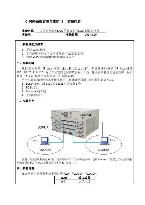
1、了解VLAN原理;
2、学会使用各种多层交换设备进行VLAN的划分;
3、理解VLAN之间路由的原理和实现方法。
二、实验环境
软件实验室的IP地址段是192.168.10.111/117,多媒体实验室的IP地址段是192.168.20.111/117,为了保证它们之间的数据互不干扰,也不影响各自的通信效率,我们划分了VLAN,使两个实验室属于不同的VLAN。
Set the port Ethernet1/6 access vlan 100 successfully
Set the port Ethernet1/7 access vlan 100 successfully
Set the port Ethernet1/8 access vlan 100 successfully
Set the port Ethernet1/19 access vlan 200 successfully
Set the port Ethernet1/20 access vlan 200 successfully
Set the port Ethernet1/21 access vlan 200 successfully
Set the port Ethernet1/9 access vlan 100 successfully
Set the port Ethernet1/10 access vlan 100 successfully
Set the port Ethernet1/11 access vlan 100 successfully
1 default Static ENET Ethernet1/25 Ethernet1/26
Ethernet1/27 Ethernet1/28
vlan间路由的实验报告

实验三Vian 之间的路由实验报告一、 实验名称:Vian 之间的路由 二、 实验目的:通过三层交换机,使分别属于两个Vian 的两台计算机之间能相互通信三、 实验设备:三层交换机一部,二层交换机一部,计算机两部,双绞线、交叉线若干 如图:3560E4PSMultilayet 1 Switch 1四、实验过程: (一)建立拓扑1、首先,对PCO 和PC1两台计算机设置如下图的网络地址;PCO匚Z- =T PCI192.16S.10.222S5.25S.25S.0 192.16B.10.1IP ConfigurationDHCP a Static2、连接好设备,构成一个简单的拓扑结构。
现在进行一次连通性的检测;Packet Tracer PC Command Line 1.0POipconf igIP Addres g _____ __ Subnet Mask.... Default; GatewayTP Address Subnet Mask Default Gateway DNS Server192.168.10.22 255.2S5.255.0 192.168.10.1甲PCI可以看出,现在两台计算机是没办法进行互相连通的;(二)两层交换机的设置1、对两层交换机switch2进行简单的基本设置,先创建两个vlan,有vlan 10 和vlan 30,并把连接PC0的接口fa/1划入vlan 10,把连接PC1的接口fa/2 划入vlan 30,如下图:Switchsccnfiguie TeminiLInter ccnfcoeraxanda, one per line . Znd with CKTI J/Z.Switch ( eonf ig) #vlati 10Switch(lsn 30Switch ( ccn^ig-vlart: f exitSwitch!ccnzig)WinterSwitch(cenfig)#im;erzaca faSwitch'' ccnf ig) Fintsrf^te f aati ttLernet 0/1Switch■:config-if)fswitchporc access vl^n 10SwlEch(config-if)#exitSwitch ;ccnf ig) interface f 丘-3/2Switch■config-ifj frawitchpcrt acceaa vlan 30Switch { can£ig-iz.- texit2、输入show vlan命令查看虚拟局域网的相关信息,看出建立vlan成功了,接口的划入也成功了;Switch#show vlanVLAN Hame Status Ps£t S1default active FaO/3,7aO/4, Fafl/5r FaO/SFaO/7,FaO/a f rsD/9r FaO/10FaG/ll F FaO/12, FaG/13, FaO/14FaO/lS r Fa0/L€r FaO/17, F B0/1^F A O/1号°Fa0/20, FaO/21, FaO/22FaO/23,Gigl/l f Gigl/210 VLAH0010 active Fa0/l30 VLAN0030 active Fi0/2(三)三层交换机的设置1、同样要对三层交换机做一些命令的设置,还是先建立两个虚拟局域网,vlan 10和vlan 30 ,见下图:Switch#conziguEe t-ennina.1Enter conf iguration ccmmands, one per line - Xnd with. CNILZZ -Switch ( config) I F vlan 10Switch ( config*vlan) #vlan 30Switch ( conf ig-vlsn) exit2、为了能实现实验目的,接下来是要进行对三层交换机中vian子接口IP地址的配置。
- 1、下载文档前请自行甄别文档内容的完整性,平台不提供额外的编辑、内容补充、找答案等附加服务。
- 2、"仅部分预览"的文档,不可在线预览部分如存在完整性等问题,可反馈申请退款(可完整预览的文档不适用该条件!)。
- 3、如文档侵犯您的权益,请联系客服反馈,我们会尽快为您处理(人工客服工作时间:9:00-18:30)。
任务vlan间路由
假设一个公司有三个部门
技术部vlan100,所处网段192.168.1.0/24 市场部vlan200,所处网段10.0.0.0/24
售后部vlan300,所处网段172.16.1.0/24
要求做到三个处在不同网段的电脑可以通信公司拓扑如下:
SW1的配置
Switch>en \\简写进入特权模式
Switch#conf t \\简写进入全局模式
Switch(config)#ho sw1 \\简写为交换机改名sw1
sw1(config)#line con 0 \\ 进入控制台
sw1(config-line)#exec-t 0 0 \\ 设置不计时挂起
sw1(config-line)#logg sy \\ 设置消息同步
sw1(config-line)#exit \\ 返回上级菜单
sw1(config)#vlan 100 \\ 启用vlan100
sw1(config-vlan)#vlan 200 \\ 启用vlan200
sw1(config-vlan)#vlan 300 \\ 启用vlan300
sw1(config)#int vlan 100 \\ 进入vlan100的虚拟接口
sw1(config-if)#ip add 192.168.1.254 255.255.255.0 \\ 为vlan100的虚拟接口设置ip地址
sw1(config-if)#no shutdown \\ 启用该接口
sw1(config-if)#int vlan 200 \\ 进入vlan200的虚拟接口
sw1(config-if)#ip add 10.0.0.254 255.255.255.0\\ 为vlan200的虚拟接口设置ip地址
sw1(config-if)#no shutdown \\ 启用该接口
sw1(config-if)#int vlan 300 \\ 进入vlan300的虚拟接口
sw1(config-if)#ip add 172.16.1.254 255.255.255.0\\为vlan300的虚拟接口设置ip地址
sw1(config-if)#no shutdown \\启用该接口
sw1(config-if)#int fa 0/1 \\进入fa0/1接口
sw1(config-if)#switchport mode trunk \\设置接口模式为干道
sw1(config-if)#int fa0/2\\进入fa0/2接口
sw1(config-if)#switchport mode trunk \\设置接口模式为干道
sw2的配置(以下配置均为简打)
Switch>en
Switch#conf t
Switch(config)#ho sw2
sw2(config)#line con 0
sw2(config-line)#exec-t 0 0
sw2(config-line)#logg sy
sw2(config-line)#exit
sw2(config)#vlan 100 !创建vlan100
sw2(config-vlan)#vlan 200 !创建vlan200
sw2(config-vlan)#vlan 300
sw2(config-vlan)#int fa 0/2 !进入fa0/2接口
sw2(config-if)#sw mo ac !接口模式设置为接入端口sw2(config-if)#sw ac vlan 100 !将接口加入vlan100
sw2(config-if)#int fa 0/3
sw2(config-if)#sw mo ac !接口模式设置为接入端口sw2(config-if)#sw ac vlan 200 !将接口加入vlan200
sw2(config-if)#int fa 0/4
sw2(config-if)#sw mo ac
sw2(config-if)#sw ac vlan 300
sw3(config-if)#int fa 0/1
sw3(config-if)#sw mo tr !将接口模式设置为干道
sw3的配置(以下配置均为简打)
Switch>en
Switch#conf t
Switch(config)#ho sw3
sw3(config)#line con 0
sw3(config-line)#exec-t 0 0
sw3(config-line)#logg sy
sw3(config-line)#exit
sw3(config)#vlan 100
sw3(config-vlan)#vlan 200
sw3(config-vlan)#vlan 300
sw3(config-if)#int fa0/2
sw3(config-if)#sw mo ac !接口模式设置为接入端口sw3(config-if)#sw ac vlan 100 !将接口加入vlan100
sw3(config-if)#int fa0/3
sw3(config-if)#sw mo ac
sw3(config-if)#sw ac vlan 200
sw3(config-if)#int fa 0/4
sw3(config-if)#sw mo ac
sw3(config-if)#sw ac vlan 300
sw3(config-if)#int fa 0/1
sw3(config-if)#sw mo tr !将接口模式设置为干道
电脑B配置如下
电脑C配置如下
电脑E配置如下
电脑F配置如下
测试连通性,在电脑A上ping其余B、C、D、E、F,如能ping通,则实验成功。
