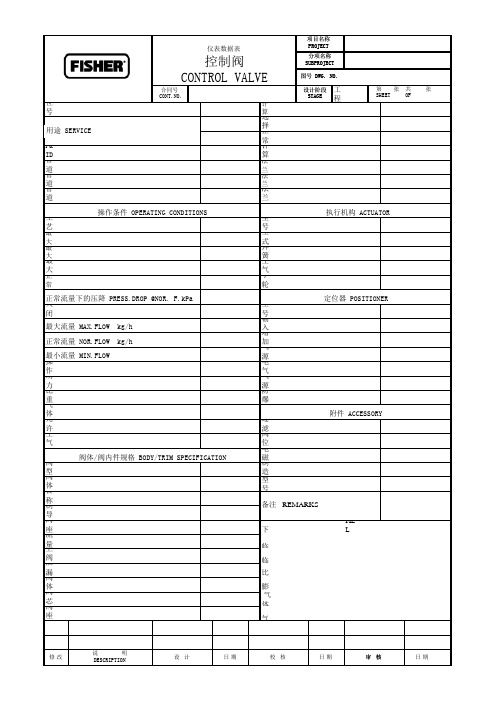
控制阀条件表
多功能水泵控制阀标准

多功能水泵控制阀标准(CJ/T167-2002)建设部于2002年6月3日批准发布了《多功能水泵控制阀》(CJ/T167-2002)城镇建设行业标准,并要求于2002年10月1日起实施。
该标准适用于公称压力为PN1.0MPa-PN4.0MPa,公称通径为DN50mm-DN1200mm的多功能水泵控制阀。
现将标准技术要求介绍如下:1 压力——温度度级多功能水泵控制阀的压力——温度等级由壳体、内件及控制管系统材料的压力——温度等级确定。
多功能水泵控制阀在某一温度下的最大允许工作压力取壳体、内件及控制管系统材料在该温度下最大允许工作压力值中的小值。
1.1 铁制壳体的压力——温度等级应符合GB/T17241.7的规定。
1.2 钢制壳体的压力——温度等级应符合GB/T9124的规定。
1.3 对于GB/T17241.7、GB/T9124未规定压力——温度等级的材料,可按有关标准或设计的规定。
2 阀体2.1 阀体法兰法兰应与阀体整体铸成。
铁制法兰的型式和尺寸应符合GB/T17241.6的规定,技术条件应符合GB/ T17241.7的规定;钢制法兰的型式和尺寸应符合GB/T9113.1的规定,技术条件应符合GB/T9124的规定。
2.2 阀体结构长度见表1。
2.3 阀体的最小壁厚铸铁件阀体的最小壁厚应符合GB/T13932-1992中表3的规定,铸钢件阀体的最小壁厚应符合JB/ T8937-1999中表1的规定。
3 阀盖膜片座3.1 阀盖与膜片座、膜片座与阀体的连接型式应采用法兰式。
3.2 膜片座与阀体的连接螺栓数量不得少于4个。
3.3 阀盖与膜片座的最小壁厚按2.3的要求。
3.4 阀盖与膜片座的法兰应为圆形。
法兰密封面的型式可采用平面式、突面式或凹凸式。
4 阀杆、缓闭阀板、主阀板4.1 缓闭阀板与阀杆应连接紧固、可靠。
4.2 缓闭阀板与主阀板的密封型式应采用金属密封的型式。
4.3 主阀板与阀杆必须滑动灵活、可靠。
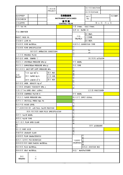
调节阀选型数据表
控制阀CONTROL VALVE工程设计位号 TAG NO.计算Cv最大/正常 CAL.Cv MAX./NOR.选择 Cv RATED Cv正常阀门开度 NOR.VALVE OPEN %P&ID号 P&ID NO.计算噪音声平 CAL.NOI.LEVEL dB(A)管道编号 LINE NO.法兰标准及等级 FLANGE STD.& DEGREE 管道材质 PIPE MATERIAL 法兰尺寸及密封面 FLAN.SIZE & SEAL.管道尺寸 PIPE SIZE法兰材质 FLANGE MATERIAL操作条件 OPERATING CONDITIONS执行机构 ACTUATOR工艺介质 PROCESS FLUID型号 MODEL /尺寸 SIZE 最大/正常流量下温度 @MAX /NOR.FLOW TEMPER.℃型式 TYPE最大流量下的入口压力 IN.PRESS.@MAX.F.kPa(g)弹簧作用 SPRING ACTION最大流量下的压降 PRESS.DROP @MAX.F.kPa空气故障阀位置 AIR FAIL VALVE 正常流量下的入口压力 IN.PRESS.@NOR. F.kPa(g)手轮 HAND WHEEL定位器 POSITIONER关闭压差 SHUT-OFF DIFFE.PRESSURE kPa-d 型号 MODEL输入信号 INPUT SIGNAL增加信号时阀位 INCREASE SIGNAL V.气源压力 AIR SUPPLY PRESS.操作密度 OPER. DENSITY kg/m 3电气接口尺寸 ELEC.CONN.SIZE 动力粘度 DYNAMIC VISCOSITY cP 气源接口尺寸 AIR SUPP.CONN.SIZE 比重 SPECIFIC GRAVITY防爆等级 EXPLOSION-PROOF CLASS气体分子量 GAS MOLECULAR WEIGHT附件 ACCESSORY允许噪音声平 ALLOWED NOISE LEVEL dB(A)过滤器减压阀 REGULATOR 空气故障时阀位置 AIR FAIL VALVE POSITION阀位开关 POSITION SWITH 阀体/阀内件规格 BODY/TRIM SPECIFICATION电磁阀 SOLENOID 阀型号 VALVE MODEL 制造厂 MANUFACTURE 阀体型式 VALVE BODY TYPE 型号 MODEL NO.公称通径 NOMINAL DIAMETER (in)制导型式 GUIDING TYPE阀座尺寸 SEAT SIZE/PORT SIZE (in) 下列数据在需要时填写。
费希尔FISHER控制阀选型参数表
定位器 POSITIONER
压缩系数 COMPRESS FACTOR K
型号 MODEL
气化压力 VAPOR PRESSURE MPa 临界压力 CRITICAL PRESS Mpa Pk 噪音声级 NOISE LEVEL 空气故障时阀位置 AIR FAIL VALVE POSITION
阀体/阀芯规格 BODY/PLUG SPECIFICATION 阀型号 VALVE MODEL 阀型式 VALVE TYPE 流开/流关 FLOW OPEN/CLOSE 阀 芯 阀口径 PORT SIZE 泄漏等级 LEAKAGE CLASS 流量特性 FLOW CHARACTENSTIC 散热片/延伸杆 FIN/EXTENTION 阀体材质/填料 BODY/PAKING MATERIAL 阀芯材质 PLUG MATERIAL
气体 GAS Nm3/h 蒸汽 VAPOR Kg/h 液体 LIQUID m3/h
操作密度 OPER. DENSITY Kg/m3
最大 MAX. 正常 NOR. 最小 MIN.
动力粘度 DYNAMIC VISCOSITY MPa.s
比重(空气=1)SPEC.GRAV.(AIR=1)
型式 TYPE 作 用弹 簧相 对手 轮供 气气 源
工程名称 PROJECT
设计项目SECTION 设计阶段STAGE
编制PREP 校核CHECK 审核APPR 位号 TAG NO.
仪表数据表
INSTRUMENT DATA SHEET
调节阀
CONTROL VALVE 计算 Cvmax.
编号 NO.
第1页 CALC.Cvmax.
版次REV. 共1页
用途 SERVICE
输入信号 INPUT SIGNAL
控制阀技术说明(ISA标准)
Control Valve Technical SpecificationThroughout this specification, where the word "shall" is used to define a requirement, Seller must comply with the requirements. Where the word "should" is used to define a requirement, Seller may select an alternative and advise Buyer acco rdingly.1 ScopeThis specification prescribes the minimum mandatory requirements governing the design, sizing, and selection of control valves.1.1 Equipment and services furnished by the Seller shall include:1.1.1 Design, fabrication, testing and delivery of all valves, complete with actuators and accessories to meet the requirements of this specification and the control valve data sheets.1.1.2 All interconnecting instrument tubing and fittings between the valve actuator, positioner, and filter regulator.1.1.3 Any special tools required for assembly, disassembly and maintenance.1.1.4 Valve drawings and calculations, including outline dimensions, weights, circuit diagrams, section drawings, part lists and materials.1.1.5 Installation, operation, and maintenance manuals, including instructions for any sub-suppliers.1.1.6 Recommended spare parts lists.1.2 Equipment and services furnished by the Buyer shall include:1.2.1 Receiving, unloading, storage, and installation of all equipment supplied by Seller.1.2.2 Electrical wiring for power and signals for position indicating lights, solenoids, and/or control stations.1.2.3 All external piping, tubing, valves, and fittings, except as specified to be furnished by the Seller.2 Conflicts and Deviations2.1 Any conflicts between this specification and other applicable industry standards, co des, and forms shall be resolved in writing by the Buyer.2.2 Seller shall direct all requests to deviate from this specification in writing to the Buyer, who shall follow internal company procedure and forward such request to the Engineering Manager, Instrumentation and Control.3 ReferencesThe selection of material and equipment, and the design and construction of the equipment covered by this specification shall comply with the applicable edition of the references in effect at the time of the Purchase Order and as noted throughout this specification.3.1 The International Society for Measurement and ControlISAGuide Control Valves, Practical Guides for Measurement and ControlISA S20.50 Specification Forms for Process Measurement and ControlInstruments, Primary Elements and Control ValvesISA S75.01 Flow Equations for Sizing Control ValvesISAS75.05 Control Valve TerminologyISA S75.11 Inherent Flow Characteristic and Rangeability of Control Valve ISA SP75.17 Control Valve Aerodynamic Noise PredictionISARP75.23 Considerations for Evaluating Control Valve Cavitation3.2 American Society of Mechanical EngineersASME B1.20.1 Pipe Threads, General Purpose (inch)ASME B16.5 Steel Pipe Flanges and Flanged FittingsASME B16.10 Face-to-Face and End-to-End Dimensions of ValvesASME B16.20 Ring-Joint Gaskets and Grooves for Steel Pipe FlangesASME B16.34 Valves - Flanged, Threaded, and Welding EndASME B31.1 Power PipingASME B31.3 Chemical Plant and Petroleum Refinery PipingASME VIII Rules for Construction of Pressure Vessels 一 Division 13.3 Fluid Control InstituteFC170-2 Control Valve Seat Leakage3.4 National Association for Corrosion Control (where applicable)NACEMR0175 Sulfide Stress Cracking Resistant Metallic Materials for Oil Field Equipment 3.5 International Electrotechnical CommissionIEC 534-8-3 Control Valve Aerodynamic Noise Prediction Method3.6 Manufacturer's Standardization SocietyMSS-SP-61 Pressure Testing of Steel Valves3.7 TerminologyThe terminology and nomenclature used in ISA S75.05, "Control Valve Terminology", and other ISA standards apply to this specification.4 Control Valve ApplicationsSeller shall select control valve design based on the requirements of the application, process operating conditions, and this specification.4.1 ApplicationsApplications, co mmon names and uses, and their key attributes covered under this specification are defined in Chapter 12 of the ISA Guide, "Control Valves, Practical Guides for Measurement and Control" and are summarized below:4.1.1 Proce ss Control/Feed RegulationApplilication Common Names and UsesFlow Control FCV, ThrottlingLevel Control LCV, Deareator, Heater DrainPressure Control PCV, InjectionPressure Reduction PRYFlow Regulation Feed Regulator, Gas RegulatorKey attributes for process control/feed regulation applications are accuracy of co ntrol resulting from small signal changes, and high rangeability resulting from increased pressure differentials that exist across the control valve during start-up, shutdown, and low-load process conditions. Seller shall select control valves that meet these attributes.4.1.2 Continuous LetdownApplilication Common Names and UsesAttemperation SprayBlowdown BDVFlow Control FCV, Mixing, Steam SupplyChoke Injection, Withdrawal, Re-InjectionLetdown Rich Amine, Drum, DrainLevel Control LCV, Flash Tank, Separator LCVPressure Control PCV, Sootblower, Steam, ReducingPressure Regulation PRY, Steam SupplyT he key attribute for continuous letdown applications is accuracy of control. Seller shall select control valves that meet this attribute.4.1.3 Intermittent LetdownApplication Common Names and UsesAnti Surge Load RejectDump Atmospheric Dump, Condenser Dump,Overboard DumpAuxiliary Aux. SteamExtraction Gas Withdrawal, Cavern Withdrawal ReliefBlowdown BDV, Steam Vent, Gas VentFlare Gas to FlareSturt-up Bypassrbine Bypass PRDSInjection Gas Injection, Steam InjectionLetdown DepressurizingKey attributes for intermittent letdown applications are tight shut-off and fast stroke speeds. Seller shall select control valves that meet these attributes.4.1.4 RecirculationApplication Common Names and UsesAnti Surge Compressor Recyc1e, Spillback, Kickback, Surge Control Bypass Start-up, Vent, Turbine BypassRecirculation Mini-flow, Leak-off, BFP RecirculationDump Overboard DumpRetumLetdownKey attributes for recirculation applications are tight shut-off, anti-cavitation and/or low noise trim, and pipe vibration elimination. Seller shall select control valves that meet these attributes.4.2 Process Operating Conditions4.2.1 Process DataFor each control valve, Buyer shall specify the process data for the following three flow conditions as a minimum: Normal Flow Rate, Maximum Flow Rate, and Minimum Flow Rate.4.2.1.1 Normal Flow RateThis flow condition is generally referred to as the design flow or material balance flow.4.2.1.2 Maximum Flow RateThis flow condition shall be consistent with the plant or equipment operational maximum flow condition. The maximum flow condition is generally the governing case for required maximum Cv capacity.4.2.1.3 Minimum Flow RateThis flow condition shall be consistent with the plant turndown requirement or equipment turndown capability. The minimum flow condition generally subjects the control valve to the highest differential pressure condition. The minimum flow conditions are generally the governing case for the required trim pef ormance.Buyer shall also specify, the minimum and normal flow conditions for control valve services identified with "normally no flow" as well as the required flow conditions during non-normal plant operating conditions such as start-up, venting,depressurizing, etc.Seller shall provide sizing calculations for all specified flow conditions.4.2.2 Data SheetsIndividual control valve specification requirements shall be specified by Buyer and/or Seller on ISA Form S20.50 data sheet (see Appendix A) or Seller's equivalent.4.2.3 Seat LeakageSeatleakage c1assification shall be in accordance with FCI 70-2 or MSS-SP- 61. The leakage class shall be determined by the service application. Soft- seated valves shall not be applied in services with design temperature conditions over 230 ° C (450 ° F) or in flashing liquid services.Leakage problems are com monly related to insufficient seat loading. While a control valve with insufficient seat loading may pass a specified leakage test after it is manufacture , the same valve will not meet the specified leakage rate after it has been subjected to thermal distortion, flashing, or erosive service.The following minimum seat load requirements (after hydraulic loads, spring loads and friction loads are considered) shall apply:Class I 一 III Per Seller's RecommendationClass IV 5.4 kgf/mm (300 Ibf/in) of seat ring circumferenceClassV 8.9 kgf/mm (500 Ibf/in) of seat ring circumferenceClassVI Per Seller's RecommendationMSS-SP-61 17.9 kgf/mm (1000 Ibf/in) of seat ring circumferenceSeat ring circumference is defined as the line of contact between the plug and the seat when the valve is in the fully closed position.The maximum shut-off diff erential pressure shall always be calculated and specified for the selected control valve. For all metal-to-metal shut-off applications equal to or exceeding FCI 70-2 Class IV requirements, actuator load calculations shall be provided. Calculations are required to show the minimum load to be applied to the plug-seat arrangement for meeting the required shut-off specifications.5 Control Valve Selection5.1 Control Valve SizingEach control valve shall be sized and selected to provide reliable operation and control at the specified operating and design conditions. Control valve sizing shall generally be based on ISAS75.01, "Flow Equations for Sizing Control Valves". Seller may deviate from the ISA formulasprovided that the reason is detailed in the technical quotation.Seller shall select and size the control valve and actuator assembly and accurately evaluate the minimum trim performance requirements.Capacity calculations for all operating conditions shall be provided. The calculation basis and results shall be shown for manual or computer calculations.5.1.1 Cv Capacity (Cv Required)The selected control valve trim capacity (Cv selected) should meet the following:5.1.1.1 An equal percentage trim shall operate below 95% travel at maximum flow.5.1.1.2 A linear trim and quick opening trim shall operate below 90% travel at maximum flow.The Cv capacity required to meet above criteria is referred to as "Cv required". The actual Cv capacity of the valve is referred to as the "Cv selected". Specific applications may require an over-sized Cv capacity, which shall be specified by the buyer.5.1.2 Piping Geometry Factor, FPFor valves mounted between pipe reducers or other pipe fittings, the calculated valve capacity shall be corrected for a decrease in valve capacity conforming to ISA S75.01. The piping geometry factors FP, control valve correction factor, calculated FLP and/or XTP factors shall be specified by the Seller.5.1.3 Body SizeControl valve bodies with reduced trims shall be considered for applications with the following conditions:- Pressure drop in excess of 5170 kPa (750 psi)一 Gas/vapor outlet velocities in excess of 0.3 Mach- High noise exceeding 85 dBA一 Choked flow- Flashing exceeding 5% weight of liquid being vaporized - Erosive fluids一 Future capacity increase is anticipatedIn all cases, the control valve nominal body size shall not exceed the nominal line size.5.1.4 Minimum RangeabilityThe installed rangeability (actual available rangeability) of each control valve in the process system shall meet all flow conditions specified. The specified minimum flow condition shall be fully controllable.5.2 Control Valve Design5.2.1 Minimum RatingThe valve shall be rated to meet the design pressure and design temperature of the application according to an internationally recognized standard.For flanged valves, the valve body rating shall never be lower than the flange rating. The flange rating for valve bodies smaller than 16-inch nominal size shall be minimum ASME Class 300. Flange rating for valve bodies 16-inch nominal size and larger shall be minimum ASME Class 150.5.2.2 MaterialsControl valve body materials shall meet, or exceed, the requirements of the application. Body and trim materials shall meet the temperature requirements. NACE MR0175, "Sulfide Stress Cracking Resistant Metallic Materials for Oil Field Equipment" shall be applied for all materials in sour fluid services.Trim materials shall be selected to withstand corrosion, erosion and wear under severe serviceco nditions. Material combinations shall be selected for maximum galling resistance. AISI 300- and 400- series stainless steel, or equivalent, shall be used as a minimum.Hard facing or heat treating shall be applied to trim seating surfaces of valves as per Seller's recommendations, but as a minimum, they shall include erosive applications, steam applicationswith pressure drop conditions exceeding 350 kPa (50 psi) andappli cations with pressure drop conditions exceeding 4000 kPa (580 psi).5.2.3 Flow DirectionFlow direction for liquid service applications shall be flow-to-c1ose. Flow direction for gas service applica tions should be flow-to-open5.2.4 Trim DesignValve trim shall be of the quick -c hange type for ease of maintenance. No internal components shall be screwed or welded into the valve bodies or bonnets. Trim shall be designed to provide equal pressurization around the plug in order to minimize vibration and prevent any potential for binding. Seller shall select control valve trim design that meets the requirements of this specification.Seller shall provide a minimum of five years experience with any proposed control valve trim design.5.2.5 End ConnectionsEnd connections shall be specified by the Buyer.5.2.5.1 Flanged ConnectionsFlanged connections shall comply with ASME B16.5. Dimensions of flanges larger than 24" size shall comply with industry standard and shall be specified by the Buyer. Raised face (RF) flanges shall be used for lines rated up to and including ASME Class 600 and up to a design temperature of 480 ° C (900 ° F). The gasket contact surface of raised face flanged valves up to and including ASME Class 600 ratings shall be smooth machine-finished.Ring joint (RT J) flanges shall be used for lines rated ASME Class 900 and above, and for design temperature conditions exceeding 480° C (900 °F). Ring grooves shall comply with ASME B 16.20.Unless otherwise noted, face-to-face dimensions of flanged valves should comply with ASME B 16.1 O. Seller to advise face-to-face dimensions proposed.5.2.5.2 Butt-Weld ConnectionsDimensions of butt-weld connections shall comply with Buyer's specification.5.2.6 Gaskets, Packing and BonnetBody gaskets for temperatures below 230°C (450°F) shall be PTFE or equal.Over 230 °C (450°F), a spiral-wound gasket, grafoil-type gasket, or equal, shall be used. In all cases, valve gaskets for body/bonnet joints or bottom flange joints shall be metal seal or spiral wound stainless steel with a non-asbestos or Teflon filler suitable for the operating and design conditions.PTFE V-ring packing shall be used for services up to 230°C (450°F).Above 230 °C (450°F), graphite or Seller's recommended packing shall be used.A standard bonnet shall be specified for temperatures of 0°C to 230°C (-32°F to 450°F). Above 230°C (450 °F) and below O°C (-32°F), an extended bonnet and/or special packing shall be considered. Seller's recommendation shall be evaluated and followed when feasible.5.3 Control Valve Performance5.3.1 NoiseThe maximum noise level emission from a control valve manifold installation, including contributions from piping elbows and reducers, shall not exceed the following limits for any specified operating condition.85 dBA for process control/feed regulation, continuous letdown, intermittent letdown daily service and recirculation daily service applications.90 dBA for infrequent letdown and recirculation applications.Noise shall be calculated in accordance with methodology outlined in ISA SP75.17 and IEC 534-8-3 guidelines. The maximum noise levels are specified in terms of equivalent continuous A-weighted Sound Pressure Levels (SPL) with an upper tolerance of +0 dBA. Seller shall be required to include inaccuracies of their quoted noise levels and shall guarantee that the noise emission from control valves, including upper tolerance, shall not exceed the above stated limits for any specified operating condition.Control valve noise shall be treated at the source except as noted below. The provision of low-noise multipath multi-stage trim designs is generally most cost- effective di ffusers, baffle plates and silencers, either inside the valve body or downstream of the valve, shall not be permitted for the following applications:Process control/feed regulation Continuous letdownIntermittent letdown in daily service Recirculation in daily serviceFor other applications, special attention shall be given to the limited flow rangeability of these devices (i.e., noise reduction from these devices is generally reduced at low flow conditions). Noise generated by diffusers or orifice plates shall be calculated by ISA SP75.17 or IEC 534-8-3 as a separate system from the valve trim and included in the overall noise source.A maximum of 5 dBA credit may be used for the application of insulation for noise reduction. Seller shall submit detailed noise cal culations with the proposal in accordance with methodology outlined in ISA SP75.17 and IEC 534-8-3 guidelines. The calculation basis and results shall be shown for manual or computer calculations. Seller shall guarantee control valve supplied meet the above requirements.5.3.2 Vibration and Erosion LimitsProper control valve selection shall ensure that the required energy can be dissipated without exceeding the maximum vibration levels in the piping system and without exceeding the wear properties of the trim material. Seller shall select control valve trim design that facilitates maximum reduction of control valve induced vibration and trim wear.Control valve vibration and trim erosion can be reduced by multi-stage multi path trim designs. In order to minimize vibration, Seller shall select control valves based on Table 12.3 of the ISA Guide, "Control Valves, Practical Guides for Measurement and Control" summarized below:5.3.2.1 Liquid Service ApplicationsThe design shall provide a sufficient number of discrete pressure drop stages to maintain the trim exit velocity below 30 m/sec (100 ft/sec) for single-phase liquids and 23 m/sec (75 ft/sec) for cavitating, flashing, and/ or erosive services. Seller shall specify number of discreet pressure drop stages required and provide body and trim exit velocity calculations with proposal. The calculation basis and results shall be shown for manual or computer calculations.5.3.2.2 Gas Service Applica tionsThe design shall provide a sufficient number of discrete pressure drop stages to maintain the trim exit fluid velocity head (V h) below 480 kPa (70 psia) for continuous or intermitt ent duty and 1030 kPa (150 psia) for infrequent duty. Valve trim exit fluid velocity head shall be calculated based on ISA Guide, "Control Valves, Practical Guides for Measurement and Control" as follows:V h = Kinetic Energy = P0*V02/(2 g c)Where:= valve trim exit fluid densityPV0= valve trim exit fluid velocity= gravitational constant in unit of measurementgcSeller shall specify number of discreet pressure drop stages required and provide body and trim exit fluid velocity head calculations with proposal. The calculation basis and results shall be shown for manual or computer calculations.5.3.3 Cavitation, Choked Flow and FlashingISA S75.01, the ISA Guide "Control Valves, Practical Guides for Measurement and Control", and the Seller's valve cavitation index data shall be used for determining the severity of cavitation, choked flow, or flashing conditions in the control valves. Seller shall provide a control valve that eliminates cavitation damage.The design of valves in cavitation and flashing service shall be based on Chapter 7 of the ISA Guide, "Control Valves, Practical Guides for Measurement and Control" and include the following techniques for Cavitation-Resistant Valves:- Reduce the pressure in multiple stages一 Direct flow away from the valve body and pipe walls - Break the flow into many small streams一 Force the flow through multiple turns or tortuous pathsThe design shall provide a sufficient number of discrete pressure drop stages to maintain the trim exit velocity below 23 m/sec (75 ft/sec) for cavitating and flashing service. Seller shall specify number of discreet pressure drop stages required and provide body and trim exit velocity calculations with Seller's proposal. For multi-constituent fluids, special consideration shall be given to the potential for cavitation of the minor components in the fluid.Contingencies on the minimum required control valve cavitation index shall be applied to compensate for inaccuracies in process data and inaccuracies in Seller's control valve cavitation index data. Buyer shall carefully evaluate Seller's selection of a control valve that eliminates cavitation.5.3.4 Flow CharacteristicSeller shall select the control valve flow characteristic to meet the rangeability requirements as defined in Section 5.1.4, Minimum Rangeability, and to provide stable control over the required range of operating conditions. Seller should select the control valve flow characteristic specified in the control valve data sheets.6 Actuator Selection6.1 Actuator SystemsSeller shall be responsible for correctly sizing the actuators based on the process operating conditions and this technical specification. Actuator systems should be pneumatic type, either diaphragm or double-acting piston. For applications with valve bodies greater than 2-inch nominal size and pressure drop in excess of 4000 kPa (580 psi), diaphragm actuators shall not be applied. Air supply system design pressure conditions are generally 930 kPag (135 psi g) or less.Control valve actuator systems other than pneumatic shall be applied on an exception basis only. For actuator systems other than pneumatic type, Seller shall submit a request to deviate in writing to the Buyer.6.2 Materials6.2.1 Actuator CylindersMaterials of the pneumatic actuators shall be suitable for the application and the operating environment.6.2.2 Pneumatic Tubing, Valves, and FittingsMaterials of the pneumatic tubing, valves, and fittings, which are to be supplied by the control valve Seller, shall be a minimum of AISI 316 stainless steel. Carbon steel, copper, bronze, brass, and AISI 304 stainless steel materials shall not be used on a control valve and actuator assembly. Air tubing, fitting or connection nipple sizes shall not be less than 1/4" NPT.6.3 Performance6.3.1 Valve Travel Position AccuracyThe total maximum inaccuracy of the valve travel position due to any limitation (i.erepeatabilit ,deadband, resolution, hysteresis, etc.) shall be less than 2.0%. 6.3.2 StabilityIn modulation, no more than one overshoot greater than 2.0% shall be observed during shop performance and field-testing. Seller shall submit test reports with proposal showing performance curve of previous experience with the same specification.6.3.3 Fail PositionAir failure position shall be accomplished without the aid of process pressure conditions. Air failure position shall be testable during inspection and during plant commissioning when piping systems are de-pressurized.When an internal spring return feature ca n not achieve the failure mode of a piston actuator, piston actuators shall be equipped with a fail-safe trip system. Boosters may be applied, as required, to meet actuator stroke response requirements on large or fast control signal changes.6.3.4 Stroke Speed RequirementsSeller shall select control valve and actuator assembly to achieve the stroke speed requirements specified on the process data sheets.All applications need to be verified for the actual stroke speed requirements. Stroke times shall be tested on a 100% control signal step change without the aid of process pressure conditions. Stroke times shall be tested during Seller's inspection. Seller shall document the test criteria and results of the functional tests performed during Seller's inspection to verify operability and stroke speed. Boosters may be applied to meet stroke time requirements, but stroke movements shall remain stable at 20%, 50%, and 80% control signal step changes.Fast stroke time requirements under failure conditions shall be separately specified. Seller may use quick-exhaust valves, provided that they do not interfere with the normal control operation of the actuator system.6.4 Actuator YokeYoke assemblies shall be cast or welded. Bolted yoke assemblies shall not be applied. Yoke assemblies shall be designed such that it will accept installation of all accessories needed to meet the requirements of the specified application.7 Accessories7.1 Positioners and Electro-Pneumatic (I/P) Transducers7.1.1 Valve positioners shall be provided with gauges to indicate supply pressure, control air signal, and positioner output pressure.7.1.2 Electro-pneumatic valve positioners and pneumatic valve positioners with integralelectro-pneumatic transducers shall not be used in potentially vibrating service conditions. The I/P transducer shall then be mounted separately from the valve and actuator assembly.7.1.3 The total maximum inaccuracy of the signal conversion in I/Ps, or electro-p neumatic valve positioners, due to any limitation (i.e., repeatability, deadband, resolution, hysteresis, etc.), shall be less than 2.0%.7.2 HandwheelsWhen handwheels are specified, handwheel installations shall meet the following requirements:- Neutral position shall be clearly indicated.- Handwheel mechanism shall not add friction to the actuator. - Maximum rim pull should be a maximum of 23 kgf (50 Ibf).7.3 Limit SwitchesLimit switches shall be actuated by a mechanical switch or proximity sensor. Limit switch enclosures shall be hermetically sealed. Switch contact outputs shall be at minimum, Single-Pole, Double-Throw (SPOT).7.4 Volume Tanks7.4.1 Minimum RatingVolume tanks shall be mechanically designed to withstand a minimum pressure of 930 kPag (135 psig). Volume tanks shall be manufactured in accordance with ASME VIII. Div. 1 (stamped UM) requirements, or equivalent.7.4.2 SizingVolume tanks shall have a minimum capacity for two complete stroke operations of the control valve at the minimum available instrument air pressure of 415 kPag (60 psig). The I/P transducer shall also be supplied from this volume tank.7.5 Position Indication7.5.1 Valve Position IndicatorEach control valve shall be provided with a valve position indicator. The indication pointer shall be directly connected to the stem or shaft. The valve position shall be indicated on a reversible scale with clearly graduated markings at 25% valve opening position intervals and the words OPEN and CLOSED at the valve travel limits.7.5.2 Valve Position TransmitterAn electronic travel position transmitter, either separate or integral to the positioner, providing a proportional valve stem or shaft position signal, shall be specified when required for remote valve position indication.7.6 Marking and Identification7.6.1 MarkingThe direction of flow shall be cast or steel-stamped on the valve body, or alternatively, a stainless steel arrow shall be perm anently fixed to the body by rivets or screws, for all appropriate valves that have been designed or selected for a specific flow direction.7.6.2 Identification。
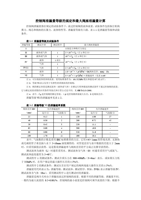
控制阀泄漏量等级的规定和最大阀座泄露漏量计算
控制阀泄漏量等级的规定和最大阀座泄漏量计算控制阀泄漏量指在规定的试验条件下,流过控制阀的流体流量。
试验条件包括执行机构推力、阀芯和阀座的压紧力、流体特性等。
泄漏量等级有六级。
表1-1是泄漏量等级和试验条件。
表1-1 泄漏量等级及试验条件 泄漏等级测试介质 测试程序最大阀座泄漏量 I由制造方和购买方商定 II液体或气体 1 5×10⁻³×C R (注1和注3) III液体或气体 1 10-3×C R (注1和注3) 液体 1或2 IV气体 1 10-4×C R (注1和注3) IV-S1气体 1 5×10⁻⁶×C R (注1和注3) V液体 2 1.8×10⁻⁷×Δp (kPa)×D(阀座直径,mm) l/h , VI 气体 1 3×10⁻³×Δp (kPa)×泄漏速率(见表4-46)注1:可压缩流体的体积流量,使用标准条件为:101.325kPa 绝压和温度0℃或15℃;注2:等级VI 表示仅用于有弹性材质阀座的控制阀;注3:阀的额定容量是测试流体(液体或气体)在额定行程和描述的测试条件下通过控制阀的流量;它与额定流量系数的应用条件判别式和计算公式是不同,见GB/T4213-2008。
注4:表中,C R 是控制阀的额定容量;Δp 是控制阀两端最大压差;D 是阀座直径。
泄漏等级VI 的泄漏速率见表1-2。
表1-2 泄漏等级VI 的泄漏速率系数允许泄漏速率 允许泄漏速率 阀座直径DN(mm ) 毫升/分 气泡数/分 阀座直径DN (mm ) 毫升/分 气泡数/分25 0.15 1 150 4.00 27 40 0.30 2 200 6.75 45 50 0.45 3 250 11.1 - 65 0.60 4 300 16.0 - 80 0.90 6 350 21.6 - 100 1.70 11 400 28.4 - 表中,气泡数的计数是采用IEC 标准推荐的方法。
控制阀标准
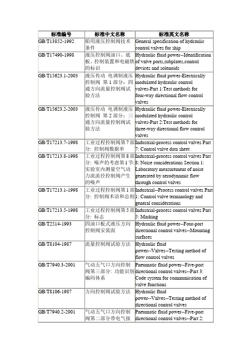
液压传动带补偿的流量控制阀安装面
Hydraulic fluid power--Compensated flow control valves--Mounting surfaces
JB/T7387-1994(2005复审)
工业过程控制系统用电动控制阀
NF C46-520-1993
NF E49-091-2002
气压传动.控制阀和其它部件的孔口和控制机械的验证
(Pneumatic fluid power - Identification of ports and control mechanisms of control valves and other components.)
NF E49-080-2-2002
气压液动.五通方向控制阀.第2部分:任选电气连接器的安装接口面
(Pneumatic fluid power - Five-port directional control valves - Part 2 : mounting interface surfaces with optional electrical connector.)
NF E48-435-1998
液压传动.尺寸02、03和05的四端口模式排气阀和四端口方向控制阀.夹紧尺寸
(Hydraulic fluid power. Four-port modular stack valves and four-port directional control valves, sizes 02, 03 and 05. Clamping dimensions.)
NF C46-510-2001
工业过程控制阀.第3-1部分:尺寸.双通球型直立式控制法兰阀门的面对面尺寸和双通球型角度控制法兰阀门的中心
气动控制阀-最新国标

目次1 范围 (3)2 规范性引用文件 (3)3 术语和定义 (3)4 产品分类及通用要求 (3)5 技术要求 (5)6 试验方法 (9)7 检验规则 (15)8 标志、包装和贮存 (16)附录A (资料性)公称通径对照表 (17)附录B (规范性)阀座泄漏量计算实例 (18)气动控制阀1 范围本标准规定了工业过程控制系统用气动控制阀的产品分类及通用要求、技术要求、试验方法、检验规则、标志、包装和贮存。
本标准适用于气动执行机构与阀组成的各类气动控制阀(以下简称控制阀)。
本标准中有关内容也适用于独立的气动执行机构和阀组件。
适用于放射性工作环境或其它危险工作环境等国家有特定要求工作条件的控制阀可参考本标准。
2 规范性引用文件下列文件中的条款通过本标准的引用而成为本标准的条款。
凡是注日期的引用文件,其随后所有的修改单(不包括勘误的内容)或修订版均不适用于本标准,然而,鼓励根据本标准达成协议的各方研究是否可使用这些文件的最新版本。
凡是不注日期的引用文件,其最新版本适用于本标准。
GB/T 13384 机电产品包装通用技术条件GB/T 17213(所有部分)工业过程控制阀GB/T 26815 工业自动化仪表术语执行器术语GB/T 9124(所有部分)钢制管法兰GB/T 12224 钢制阀门一般要求GB/T 26640 阀门壳体最小壁厚尺寸要求规范IEC 60534 Industrial-process control valves3 术语和定义GB/T 17213及GB/T 26815确立的术语和定义适用于本标准。
4 产品分类及通用要求4.1 按控制阀动作方式分类a)直行程控制阀;b)角行程控制阀;4.2 按控制阀使用功能分类a)调节型;b)开关型;4.3 按控制阀作用方式分类a)气关式;b)气开式。
4.4 按控制阀执行机构型式分类a)薄膜式气动控制阀;b)活塞式气动控制阀。
注1:气动执行机构按结构分为:a)薄膜式气动执行机构;b)活塞式气动执行机构。
调节阀法兰距、外型尺寸
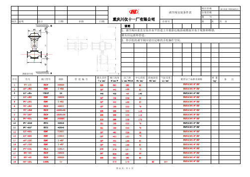
版次说明设计日期审核日期合同号第页共 页说明薄膜调节阀序号位号阀门型号规格管 道 编 号膜头直径ΦA(mm)阀门高度H(mm)P法兰距L(mm)PN16中心高度H1(mm)距地高度H2(mm)气缸长度L1(mm)配管法兰标准及规格重 量(kg)备 注1TV-153HCP 80X80363635298982AV-1602HPF 3/4X8267445180653LV-1601VBSF 80440420461404LV-1605HPF 50X50267523250885PV-1601HPF 3/4X5267445180656TV-1605HCP 40X25267500222707TV-1606HCP 100X1003636603521138TV-2007HCP 100X1003636603521139PV-4001HPF 100X6535069935017010PV-4006HTS 40X402815002227011PV-4007HTS 40X402815002227012LV-4001HPF 32X322674952208013LV-4002HPF 25X252674851857014AV-1202HPF 3/4X72674451806515AV-1203HPF 3/4X72674451806516FV-4501HLS 25X142303751844017XV-402HCP 50X502675002548018XV-403HCP 80X803636352989819XV-2001ZJHR2534314060204HG20592-97 RFHG20592-97 RF HG20592-97 RF HG20592-97 RF HG20592-97 RF HG20592-97 RF HG20592-97 RFHG20592-97 RF HG20592-97 RF HG20592-97 RF HG20592-97 RF HG20592-97 RF HG20592-97 RF HG20592-97 RF HG20592-97 RF HG20592-97 RF HG20592-97 RF HG20592-97 RF HG20592-97 RF 1、调节阀应垂直安装在水平管道上尽量靠近地面或楼面并易于观察和维修,膜头应远离热管道。
阀门使用技术条件

阀门使用技术条件阀门是工业生产中常用的控制装置,用于控制流体的流量、压力和方向。
阀门使用技术条件是指在使用阀门时需要满足的一些技术要求和标准。
本文将从阀门的工作条件、使用环境、材料要求等方面介绍阀门使用技术条件。
一、阀门的工作条件1. 温度范围:阀门在不同工作条件下需要承受不同的温度,因此在选择阀门时需要考虑其能够适应的温度范围。
常见的阀门材料如碳钢、不锈钢、铸铁等都有其对应的温度范围。
2. 压力等级:阀门在工作中需要承受一定的压力,因此需要选择适合的阀门压力等级。
常见的阀门压力等级有PN、Class、MPa等,需要根据实际工作条件选择合适的阀门。
3. 流量要求:阀门的流量要求是指阀门在工作中需要控制的流体流量大小。
根据流量要求选择合适的阀门口径和流量特性,以确保阀门的正常工作。
二、阀门的使用环境1. 介质性质:阀门需要处理的介质可能是液体、气体或者固体颗粒等,不同的介质对阀门的要求也不同。
液体介质可能会腐蚀阀门,气体介质可能会对阀门的密封性产生影响,固体颗粒可能会磨损阀门的密封面等。
2. 工作压力:阀门在使用时需要承受的工作压力也是一个重要的考虑因素。
对于高压阀门,需要选择能够承受高压的结构和材料。
3. 环境温度:阀门的使用环境温度可能会影响阀门的材料性能和密封性能,因此需要根据使用环境的温度选择合适的阀门材料。
三、阀门的材料要求1. 阀体材料:阀门的阀体材料需要具备一定的强度和耐腐蚀性。
常见的阀体材料有碳钢、不锈钢、铸铁、铜合金等。
2. 密封材料:阀门的密封材料需要具备良好的密封性和耐腐蚀性。
常见的密封材料有橡胶、聚四氟乙烯、金属等。
3. 阀杆材料:阀门的阀杆材料需要具备一定的强度和耐腐蚀性,以确保阀门的正常开闭。
常见的阀杆材料有不锈钢、碳钢等。
四、阀门的其他要求1. 操作方式:阀门的操作方式可以是手动、电动、气动等。
需要根据实际情况选择合适的操作方式。
2. 寿命要求:阀门的寿命要求是指阀门在使用过程中需要达到的使用寿命。
自动控制条件表

混床旁路系统差压变送器,压差高报 5 警及联锁
PdI CRT 2
0.35~0MPa 凝结水 60
4
/
/
/ Φ426×11 钢20 / / / / /
/
/
联锁内容:当混床进出水母管差压>0.35MPa时,混床旁路电动阀自动打开、压差信号送至主控制室。混床进水阀、出水阀自动关闭,混床系统全部停运。
6 高混进水压力指示
自动控制条件表
序号 一、温度T (℃)
名称
工程名称:
测量范围
控制方 监视 数 式 地点 量
最 高
正 常
最 低
工艺介质特性(最大值)
名称
温度 表压 流量 粘度 ℃ MPa m3/h PaS
设备 材质
资料编号:
工艺管道 与工艺管道连接形 测前 测后 允许最
规格
材质
法兰 PN DN 标准
其 它
表压 表压 大压力 MPa MPa 损失
工程名称:
测量范围
控制方 监视 数 式 地点 量
最 高
正 常
最 低
CI CRT 2 50 ~0 .2us/cm
CI CRT 2 0.2~0us/cm
工艺介质特性(最大值)
名称
温度 表压 流量 粘度 ℃ MPa m3/h PaS
设备 材质
凝结水 50 4
/
/
/
凝结水 50 4
/
/
/
资料编号:
工艺管道 与工艺管道连接形 测前 测后 允许最
/
Φ108×4 不锈钢 / / / / /
/
/
13
联锁内容:当出水压力<0.2MPa时,禁止执行再生程序及混床树脂输送程序。
控制阀 技术参数

控制阀技术参数嘿,咱今儿就来聊聊控制阀的技术参数,这可真是个相当重要的事儿呢!你想啊,控制阀就像是一个管道系统里的指挥官,指挥着流体的流向和流量。
那它得有一系列厉害的技术参数来保证自己能出色地完成任务呀!先说说公称通径吧,这就好比是一条道路的宽窄。
如果通径太小,那流体通过就像小马拉大车,费劲得很;要是通径太大呢,又可能会造成资源浪费。
所以得根据实际需求,选择合适的公称通径,这多关键啊!然后是压力等级。
这就像是给控制阀设定了一个能承受的压力上限,要是超过了这个上限,那可不得了,说不定就“崩溃”啦!不同的工况需要不同的压力等级,得好好斟酌才行。
流量特性也不能小瞧呀!它决定了控制阀对流体流量的控制精度和响应速度。
就像一个司机,得能精准地控制车速,该快就快,该慢就慢。
如果流量特性不好,那整个系统的运行不就乱套啦?还有密封性能,这可是保证系统不泄漏的关键呀!要是密封不好,那流体到处乱跑,不就跟没了缰绳的野马似的,那还得了?再说说动作时间吧,这可关系到控制阀反应的快慢呢。
在一些紧急情况下,要是它慢悠悠的,那不就误大事啦?哎呀,你看看这些技术参数,哪一个不重要呢?就像人一样,得各方面都优秀,才能在社会上立足呀!一个好的控制阀,就得靠这些技术参数来撑场面。
你想想,如果一个控制阀的技术参数不过关,那会带来多少麻烦呀!系统运行不稳定,效率低下,甚至可能引发安全问题。
这可不是闹着玩的呀!所以呀,在选择控制阀的时候,可一定要瞪大了眼睛,仔细研究这些技术参数。
别嫌麻烦,这可是为了保证系统的稳定运行和高效工作呢!可别随便找个差不多的就用上了,那可不行!咱得对自己的工程负责,对不对?总之呢,控制阀的技术参数就是它的灵魂,没有这些过硬的参数,它可就没法好好发挥作用啦!咱可得重视起来,让这些小小的控制阀在各自的岗位上发挥出大大的能量!你说是不是这个理儿呢?。
常用阀门标准表
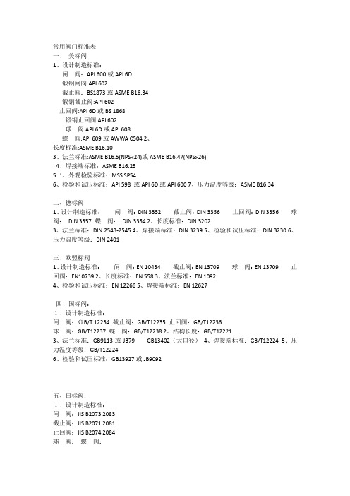
常用阀门标准表一、美标阀1、设计制造标准:闸阀:API 600或API 6D锻钢闸阀:API 602截止阀:BS1873或ASME B16.34锻钢截止阀:API 602止回阀:API 6D或BS 1868锻钢止回阀:API 602球阀:API 6D或API 608蝶阀:API 609或AWWA C504 2、长度标准:ASME B16.103、法兰标准:ASME B16.5(NPS<24)或ASME B16.47(NPS>26)4、焊接端标准:ASME B16.255‘、外观检验标准:MSS SP546、检验和试压标准:API 598 或API 6D或API 6007、压力温度等级:ASME B16.34二、德标阀1、设计制造标准:闸阀:DIN 3352 截止阀:DIN 3356 止回阀:DIN 3356 球阀:DIN 3357 蝶阀:DIN 33542、长度标准:DIN 32023、法兰标准:DIN 2543-25454、焊接端标准:DIN 32395、检验和试压标准:DIN 32306、压力温度等级:DIN 2401三、欧盟标阀1、设计制造标准:闸阀:EN 10434 截止阀:EN 13709 球阀:EN 13709 止回阀:EN107392、长度标准:EN 5583、法兰标准:EN 10924、检验和试压标准:EN 122665、焊接端标准:EN 12627四、国标阀:1、设计制造标准:闸阀:GB/T 12234 截止阀:GB/T12235 止回阀:GB/T12236球阀:GB/T12237 蝶阀:GB/T12238 2、结构长度:GB/T122213、法兰标准:GB9113或JB79 GB13402(大口径)4、焊接端标准:GB/T122245、压力温度等级:GB/T122246、检验和试压标准:GB13927或JB9092五、日标阀:1、设计制造标准:闸阀:JIS B2073 2083截止阀:JIS B2071 2081止回阀:JIS B2074 2084球阀:蝶阀:2、结构长度:JIS B20023、法兰尺寸:JIS B2212 22144、压力温度:JIS B2073 20835、压力测试:JIS B2003 六:英标阀门1、闸:BS 1414 截止:BS1873 止回:BS 1868 球阀:BS5351 蝶阀:BS51552、焊接端:BS 20803、法兰端:BS 4504 BS15604、检验:BS51465、压力温度BS12516 15606、防火:BS 6755。
阀门质量控制点一览表

签字确认和批准
检验责任师
2
检验过程
▲1、DN32以上部件炉号和追溯号
▲2、阀体最小厚度
▲3、法兰厚度
▲4、要求Ra0.8时,内孔粗糙度
▲5、有追溯要求的化学成份和机械性能
▲6、自检单审核
●7、DN65及以上阀门组装首件检查
●8、组装后开关三次
★9、水压气密试验
▲10、包装检查(含TS标识等)
购买申请
设备责任师
2、
设备管理
▲建帐建档
1、使用说明书、出厂合格证、随机附件清单、大修记录
2、运转记录、保养、维修、事故记录
设备和检验与试验装置控制程序
设备台帐、档案
设备责任师
3、
设备使用
▲定机定人
1、人员资格2、定机定人
3、专用标牌4、操作规程
1、设备和检验与试验装置控制程序
2、人员培训、考核及其管理程序
1、《设备和检验与试验装置控制程序》
1、工装设计图纸
2、采购单
3、工装使用验证
1、技术责任师
2、设备责任师
三、材料和零部件控制系统
(6个环节、1个停止点、、9个审核点、3个见证点)
序号
环节名称
工作程序和控制点
规 定 和 要 求
工作依据
工作见证
责 任 人
1
采购订货
▲1、采购合同审批
▲2、合格供应商确认
1、《文件控制程序》
2、国家有关现行法规、标准
1、图纸及技术文件审查单
2、零部件图
3、组装图
4、设计更改批准
1、技术责任师
2、工艺责任师
二、工艺控制系统
(2个环节、6个审核点)
控制阀数据表

项目Item:日期Date:★★★★MAX.NOR.★MAX.NOR.★MAX.NOR.★★★★★标准型 PLAIN延伸杆 EXTENTION波纹管 BELLOWS ★★★★★★★★★★★★★★★★★★★★★★★★★★★备注REMARKS 控制阀数据表CONTROL VALVE DATA SHEET 散热片 FIN输入信号 INPUT SIGNAL 气源接口尺寸 AIR ENTRY 防爆(护)等级 EXPLOSION-PROOF CLASS防护等级 PROTECTION CLASS电气接口尺寸 ELEC.CONN.SIZE电磁阀SOLENOID VALVE 限位开关LIMIT SWITCHES 过滤器减压阀型号 MODEL 电源 POWER SUPPLY 限位开关型号 MODEL 连接形式 CONNECTION TYPE法兰尺寸、等级及密封面 CONNECTION SIZE/RATING/FACING动力粘度 DYNAMIC VISCOSITY mpa s故障时阀位置 FAIL POSITION电气接口尺寸 ELEC.CONN.SIZE电磁阀形式 TYPE 液体 LTQUID m 3/h气体 GAS Nm 3/h 进口压力 INLET PRESS Bar(G)出口压力 OUTLET PRESS.Bar(G)阀关闭差压 SHUT-OFF DIFF.PRES.Bar流量 FLOW 蒸气 VAPOR Kg/h附件 ACCESSORY工艺介质 PROCESS FLUID操作温度 OPER.TEMPER.℃操作条件 OPERATING CONDITIONS过滤器减压阀AIR REGULATOR 气源压力 AIR SUPPLY PRESSURE Bar★★定位器POSITIONER 气源接头 AIR CONN.SIZE形式 TYPE手轮 HAND WHEEL供气压力 AIR SUPPLY PRESS.执行机构 ACTUATOR阀体/阀芯规格 BODY/PLUG SPECIFICATION流量特性 FLOW CHARACYENSYIC阀体材质 BODY MATERIAL阀芯材质 TRIM MATERIAL阀座材质 SEAT MATERIAL阀体型式 VALVE TYPE阀门口径 VALVES SIZE上盖形式 BONNET TYPE上海华麒流体设备有限公司Wachi Fluid Equipment CO.,LTD.电气接口尺寸 ELEC.CONN.SIZE位号 TAG NO.用途 SERVICE型号 MODEL 填料材质 PACKING MATERIAL 计算Cv CALC.Cv 选择Cv RATED Cv 泄漏等级 LEAKAGE CLASS。
水利控制阀设计标准

水利控制阀设计标准一、定义和分类水利控制阀是一种用于控制水流、水压和水位的设备,它具有开启、关闭、调节等功能。
根据用途和控制方式的不同,水利控制阀可分为闸阀、截止阀、止回阀、球阀、蝶阀等多种类型。
二、材料和结构水利控制阀的制造应采用耐腐蚀、耐磨损、抗老化、易加工、易维修的材料,如不锈钢、铸钢、铸铁等。
结构上应简单、紧凑、易于操作,并符合相关标准和规范。
三、性能要求水利控制阀应具有以下性能要求:1.密封性能好,能够保证水流不泄漏或少泄漏。
2.开启和关闭迅速,调节水流稳定可靠。
3.能够承受水流的冲击力和压力,保证设备的稳定性和安全性。
4.适应不同的水质和水温条件,不易腐蚀和磨损。
5.便于维护和检修,使用寿命长。
四、试验方法水利控制阀的试验方法应符合相关标准和规范的要求,主要包括以下试验:1.密封试验:在规定的水压下,对阀门的密封面进行加压,观察泄漏情况,保证密封性能符合要求。
2.强度试验:对阀门进行水压试验,观察阀门的强度和稳定性,保证设备的安全性。
3.动作试验:对阀门的开启和关闭进行试验,观察阀门的动作是否灵活、可靠,调节功能是否正常。
4.耐腐蚀试验:在规定的水质和水温条件下,对阀门进行浸泡或冲刷试验,观察阀门的耐腐蚀性能。
五、标志、包装和储存水利控制阀的标志应清晰、易读,包括产品名称、型号、规格、生产厂家等信息。
包装应采用防潮、防尘、防震等措施,确保设备在运输和储存过程中不受损坏。
储存环境应干燥、通风良好,避免阳光直射和高温环境。
六、安装使用水利控制阀的安装使用应符合相关标准和规范的要求,主要包括以下方面:1.根据工程需要选择合适的阀门类型和规格,按照说明书的要求进行安装。
2.阀门应安装在平整、稳固的基础上,确保设备的稳定性和安全性。
3.阀门的操作应灵活、可靠,调节功能正常。
在使用过程中,应定期进行检查和维护,确保设备的正常运行。
4.在使用过程中,如发现阀门有故障或异常情况,应及时进行处理或更换部件。
压力控制器、膨胀阀、电磁阀、安全阀、止回阀、压差阀执行标准

压力控制器、膨胀阀、电磁阀、安全阀、止回阀、压差阀执行标准下载提示:该文档是本店铺精心编制而成的,希望大家下载后,能够帮助大家解决实际问题。
文档下载后可定制修改,请根据实际需要进行调整和使用,谢谢!本店铺为大家提供各种类型的实用资料,如教育随笔、日记赏析、句子摘抄、古诗大全、经典美文、话题作文、工作总结、词语解析、文案摘录、其他资料等等,想了解不同资料格式和写法,敬请关注!Download tips: This document is carefully compiled by this editor. I hope that after you download it, it can help you solve practical problems. The document can be customized and modified after downloading, please adjust and use it according to actual needs, thank you! In addition, this shop provides you with various types of practical materials, such as educational essays, diary appreciation, sentence excerpts, ancient poems, classic articles, topic composition, work summary, word parsing, copy excerpts, other materials and so on, want to know different data formats and writing methods, please pay attention!压力控制器、膨胀阀、电磁阀、安全阀、止回阀、压差阀执行标准1. 导言在工业领域,压力控制器、膨胀阀、电磁阀、安全阀、止回阀、压差阀等设备在各种系统中扮演着至关重要的角色。
控制阀条件表

初 饱和 气(电)源 压 临界 蒸汽 故障时阀的 泄 算 缩 运动 压力 压 漏 Cv 粘度 状态 系 Pc mPa·s Pv 量 值 数 kPa kPa 最大 正常 最小 开 关 保持 气体Nm³/h 蒸汽kg/h 液体m³/h 11 12 13 14 15 16 17 18 19 20 21 22
唐山三友硅业 有限责任公司
控 制 点
工程名称 设计项目 设计阶段
控制阀条件表
调 节 介 质 调节阀(kPa,A) 流量
提出人 校 核 审 核 控 制 要 求
编号 第 页 控制阀位置 共 页
序 号
位 号
名
称
密度 介质 温 数 液:kg/m³ 或 度 量 气:kg/Nm 成份 ℃ ³ 4 5 6 7
阀 关闭 阀前 后 时压 压力 压 差 力 8 9 10
管段号 管段规格材质
备注
1
2
3
23
24
25
26
说明:用于切断阀时应在备注栏注明阀门开启或者关闭时间。
120控制阀

• TWG-1系列空重车自动调整装置
TWG-1型自调装置可适用于21t、23t、25t轴重采用K2、K4、K5、K6 转向架的货车,能适应在侧架内、外侧及中梁附近等各种安装位置具有很 强的适应能力。
TWG-1型空重车自调装置由T-1型调整阀和WG-1型传感阀(以下分别简 称调整阀和传感阀)两部分组成。T-1型调整阀串接在120或GK阀通往制动 缸的管路中,而WG-1型传感阀则安装在转向架摇枕上或转向架附近的车 体上,其挡铁则设在横跨梁或侧架上。
mm序号缩孔部位孔径1紧急活塞杆上紧急室充气限制孔052紧急活塞杆上紧急室排气限制孔113紧急活塞杆稳定限制孔254主阀安装面局减室排气限制孔085滑阀充气限制孔206滑阀减速充气限制孔197254mm制动管充气限制缩堵孔188254mm制动缸缓解限制缩堵孔299356mm制动缸缓解限制缩孔3610254mm制动缸用紧急二段阀缩堵孔2411滑阀加速缓解风缸充气限制孔0912滑阀逆流孔0213滑阀下面ju3限制孔仅1201阀有0614f7限制孔仅1201阀有2专业资料组装与试验120阀与12011阀的滑阀节制阀稳定簧座主阀上盖不得互换
空气制动装置检修 通用要求
2008.06 哈尔滨
1. 120/120-1型控制阀
1.1 120阀的特点
• 120阀为二压力机构阀。 • 采用直接作用方式。 • 主控机构采用橡胶膜板和金属滑阀结构。 • 采用常用制动与紧急制动分部作用的方式以及完善的两阶段局减作用。
设有紧急二段阀,紧急制动时制动缸压力呈先快后慢的两段上升方式。
单位:mm
孔径 Φ0.5 Φ1.1 Φ2.5 Φ0.8 Φ2.0 Φ1.9 Φ1.8 Φ2.9 Φ3.6 Φ2.4 Φ0.9 Φ0.2 Φ0.6 Φ2
自控阀门技术参数

自控阀门技术参数1.流体介质参数:-流体介质类型:自控阀门可以适用于不同的介质,如气体、液体、蒸汽等。
-温度范围:自控阀门应能在不同的温度范围内正常工作,需要具备一定的耐温性能。
-压力范围:自控阀门应能在不同的压力范围内正常工作,需要具备一定的耐压性能。
-流量范围:自控阀门应能适应不同的流量范围,从小流量到大流量都能实现精确的控制。
2.阀门参数:-阀门类型:自控阀门可以根据需要选择不同的阀门类型,如截止阀、调节阀、球阀等。
-阀门尺寸:自控阀门应根据管道的尺寸选择合适的阀门尺寸,以确保流体能够顺畅地通过。
-阀门材质:自控阀门应根据流体介质的特点选择合适的材质,如不锈钢、铸铁、铜等。
-阀门连接方式:自控阀门可以有多种连接方式,如法兰连接、螺纹连接、焊接连接等。
3.控制参数:-控制方式:自控阀门可以实现不同的控制方式,如手动控制、电动控制、气动控制、液动控制等。
-控制精度:自控阀门应具备较高的控制精度,能够实现精确的流量、压力、液位等参数的调节。
-控制速度:自控阀门应具备快速的响应速度,能够及时调节流体参数,满足工艺要求。
-控制信号:自控阀门接受不同的控制信号,如电流信号、电压信号、气压信号等,以实现自动控制。
4.其他参数:-密封性能:自控阀门应具备良好的密封性能,避免流体泄漏。
-耐腐蚀性能:自控阀门应具备一定的耐腐蚀性能,能够适应腐蚀性介质的控制要求。
-耐磨性能:自控阀门的阀芯和阀座应具备较高的耐磨性能,以确保长时间的使用寿命。
-可靠性能:自控阀门应具备良好的可靠性能,能够长时间稳定地工作,不易出现故障。
综上所述,自控阀门的技术参数是多方面的,如流体介质参数、阀门参数、控制参数等,这些参数将直接影响到自控阀门的性能和控制效果。
在选择和应用自控阀门时,需要根据具体的工艺需求和介质特性来确定合适的技术参数,以确保自控阀门的稳定性和可靠性。
- 1、下载文档前请自行甄别文档内容的完整性,平台不提供额外的编辑、内容补充、找答案等附加服务。
- 2、"仅部分预览"的文档,不可在线预览部分如存在完整性等问题,可反馈申请退款(可完整预览的文档不适用该条件!)。
- 3、如文档侵犯您的权益,请联系客服反馈,我们会尽快为您处理(人工客服工作时间:9:00-18:30)。
备注
15
16
17
名称
控制阀条件表
仪表条件表 设计项目 设计阶段 控制点 调节阀(kPa,A) 温度及 标况密 数 名称或成 变化范 度 量 分 围 关闭时 阀前 阀后 kg/m3 ℃ 压差 压力 压力 提条件专业 工艺/系统 调节介质 最大流量 正常流量 最小流量 压缩系数 气体Nm3/H;蒸汽kg/h;液体m3/h 接受条件专业
序 号
位号 或 回路号
设备名称
1
2
3
4
5
6
7
8
9
10
11
12
13
14
提出人 校核 仪表 审核 控制要求 故障状态 O开 C管 R保持 18 泄漏量 控制阀位置
编号
条件表
第 页 共 页
临界 饱和 动力粘度 压力 蒸汽 mPas Pc 压 kPa
初算Cv 值
管段号 或 设备号
管段规格 或 设备规格
管道 材质
