FTC334E 触摸芯片
FTS触摸屏及IC相关知识介绍

1、自电容触摸屏(Self Capacitive Touch) 2、互电容触摸屏(Mutual Capacitive Touch)
4
Proprietary and Confidential
FTS触摸屏IC方案
3.5”以下panel对应电路方案
FT5206 3.8”以下panel对应电路方案
FT5202、FT5201+C8051F921 5.7”以下panel对应电路方案
FT5302、FT5306、FT5301+C8051F921 、FT5301+C8051F342 8.9”以下panel对应电路方案
6
Proprietary and Confidential
表面式电容屏与投射式电容屏两者区 别
表面式电容屏:技术成熟,不能识别多点, 价格高,有战略联盟,能做各种尺寸屏。
投射式电容屏:技术不成熟,能识别多点, 适合做中小尺寸屏。
7
Proprietary and Confidential
自电容
FPC layout 规则
FPC Layout 一般规则 FTS电容屏方案FPC Layout规则
17
Proprietary and Confidential
FPC Layout 一般规则
•信号线线宽一般最小为0.075mm; •信号线安全间距一般最小为0.075mm; •过孔外径和内径一般最小为0.4mm和0.2mm; •铺铜安全间距至少为信号线安全间距的2倍,一般设置最 小设置为0.2mm; •FPC铺铜和边缘走线离FPC outline一般最小安全间距为 0.2mm。
TH01韩国ADS一键触摸按键IC
TH01(1-CH Differential Sensitivity Calibration Capacitive Touch Sensor) 1Specification1.1General featuresTH01 SOT-26 (Drawings not to scale)® TH01 (1-CH Differential Sensitivity Calibration Capacitive Touch Sensor)ADSemiconductor Confidential 2/132 Pin Description (SOT-26)PIN NumberName I/ODescription Protection1 OUTPUT Digital OutputTouch detect output VDD/GND 2VDDPowerPower (2.5V ~ 5.0V) GND 3 SYNCAnalogInput/OutputSelf operation signal outputPeripheral operation signal input Sensitivity selection input [Note1]VDD/GND 4 CS Analog Input Capacitive sensor input VDD/GND 5 GND Ground Supply ground VDD6 CR Analog Input Reference capacitive sensor inputfor differential sensitivity calibration and initial touch detect [Note2]VDD/GNDNote1 : Refer to chapter 6.3, 6.4 SYNC implementationNote2 : Touch during reset time can be detected by differential detect method of TH013 Absolute Maximum RatingSupply voltage 5.5 V Maximum voltage on any pin VDD+0.3 V Maximum current on any PAD 100mA Continuous power Dissipation 200mW Storage Temperature -50 ~ 150℃ Operating Temperature -20 ~ 75℃ Junction Temperature 150℃Note3 : Unless any other command is noted, all above are operated in normal temperature.4 ESD & Latch-up Characteristics4.1 ESD characteristicsMode Polarity Minimum LevelReference 8000V VDD 8000V VSS H.B.MPos / Neg8000V P to P 500V VDD 500V VSS M.M Pos / Neg 500V P to P C.D.MPos / Neg800VDIRECT4.2 Latch-up characteristicsMode PolarityMinimum Level Test Step Positive 25mA ~ 100mA I TestNegative -25mA ~ -100mA25mA V supply over 5.0VPositive1V ~ 7.5V0.51.0V® TH01 (1-CH Differential Sensitivity Calibration Capacitive Touch Sensor)ADSemiconductor Confidential 3/135 Electrical Characteristics▪ V DD =3.3V (Unless otherwise noted), T A = 25℃Characteristics Symbol Test Condition Min Typ Max Units Operating supply voltage V DD2.53.3 5.0 V V DD = 3.3V - 15 25 Current consumptionI DDV DD = 5.0V- 30 50 ㎂ Output maximum sinkcurrentI OUTT A = 25℃ - - 4.0㎃ Internal reset criterionV DD voltage V DD_RST T A = 25℃- - 0.3∙V DDVSense inputcapacitance range[Note4]C S --100Reference inputcapacitance range[Note5]C R - - 100 ㎊Sense (Reference) inputresistance range R S , R R- 200 1000 Ω Minimum detectablecapacitance variation ΔC S C S = 10pF0.2 - - ㎊ΔC S > 0.2pF - 12 -Output impedance (open drain) Zo ΔC S < 0.2pF - 30M - ΩSelf calibration time after V DD settingT CAL - 200 - ms Maximum supply voltagerising time T R_VDD - - 100 ms Recommended sync resistance range R SYNC1220MΩNote 4:The sensitivity can be increased with lower C S value.The recommended value of C S is different from each other application. 10pF is recommended when using 3T PC(Poly Carbonate) cover and 10㎜ x 7㎜ touch pattern used.Note 5: Recommended C R value is C S_TOT +ΔC S /2 – C R_PARA < C R <C S_TOT +ΔC S - C R_PARA forproper initial touch detect. Large C R value makes initial touch invalid, and small C R value can cause abnormal initial touch detect.- C S_TOT is the sum of C S and parasitic capacitance at CS pin (C S_PARA ). - ΔC S is the capacitance variation made by correct touch.TH01(1-CH Differential Sensitivity Calibration Capacitive Touch Sensor) 6TH01 ImplementationTH01(1-CH Differential Sensitivity Calibration Capacitive Touch Sensor) 6.2CS and CR implementationR SCCTH01(1-CH Differential Sensitivity Calibration Capacitive Touch Sensor)Sensitivity example figure of TH01 (when normal sensitivity selection selected) 6.3 SYNC implementationSYNCTH01(1-CH Differential Sensitivity Calibration Capacitive Touch Sensor) 6.4SYNC implementation for sensitivity selection.VDD SYNC<<TH01(1-CH Differential Sensitivity Calibration Capacitive Touch Sensor)7Recommended Circuit DiagramThe values of C S and C R depend on sensor pattern and peripheral condition. The C R should be bigger than C S_TOT. (See 6.2 CS and CR implementation, C S_TOT+ΔC S/2 <C R+C PARA< C S_TOT +ΔC S) The C S pattern should be routed as short as possible and the width of line might be about 0.25mm. The SYNC pin should be connected to R SYNC (or VDD, GND). (See 6.3, 6.4 SYNC pin implementation chapters)From two TH01 to ten TH01 (or other TS series touch sensor) can work on the one application at the same time thanks to SYNC function.(Refer to chapter 6.3)The capacitor that is between VDD and GND is optional. It should be placed as close as possible from TH01.® TH01 (1-CH Differential Sensitivity Calibration Capacitive Touch Sensor)ADSemiconductor Confidential 9/137.2 Application example (Normal Touch Sensor application)Refer to 7.1 Application example (Capacitive Hall Sensor application).® TH01 (1-CH Differential Sensitivity Calibration Capacitive Touch Sensor)ADSemiconductor Confidential 10/137.3Example - Power Line Split StrategyA. Not split power line (Bad power line design)The noise that is generated by power load or relay can be loaded at Sensor IC power line. A big inductance might be appeared in the case of connection line between power board and display board is too long, moreover the voltage ripple could be generated by digital load such as LED (LCD) display driver on V DD line.B. Split power line (One V DD regulator used) – RecommendedC. Split power line (Separated V DD regulator used) – Strongly recommendedTH01(1-CH Differential Sensitivity Calibration Capacitive Touch Sensor) 8PACKAGE DESCRIPTIONTH01(1-CH Differential Sensitivity Calibration Capacitive Touch Sensor) NOTE:1. Dimensions and tolerances are as per ANSI Y14.5, 1982.2. Package surface to be matte finish VDI 11 ~ 13.® TH01 (1-CH Differential Sensitivity Calibration Capacitive Touch Sensor)ADSemiconductor Confidential 13/13NOTES:LIFE SUPPORT POLICYAD SEMICONDUCTOR’S PRODUCTS ARE NOT AUTHORIZED FOR USE AS CRITICAL COMPONENTS IN LIFE SUPPORT DEVICES OR SYSTEMS WITHOUT THE EXPRESS WRITTEN APPROVAL OF THE PRESIDENT AND GENERAL COUNSEL OF AD SEMICONDUCTOR CORPORATIONThe ADS logo is a registered trademark of ADSemiconductorⓒ 2006 ADSemiconductor – All Rights Reserved www.adsemicon.co.kr。
Crestron快思聪触摸屏

数字控制杆相机控制器
C2N-CAMIDSPT
数字化伺服左右/上下摇动镜头
控制主机附件, 电缆及电源供应器
CNXAO-8
快思聪 CNXAO-8 模拟输出扩展卡
CNXIO-16
快思聪 CNXIO-16 数字/模拟I/O 扩展卡
CNXMIDI
快思聪 CNXMIDI MIDI界面扩展卡
CNXRY-16
快思聪 AV2经济双总线控制系统
PW-1830RU
快思聪 CP2 精巧型控制系统
QM-FTCMK
CP2E 精巧型控制系统,以太网接口
QMI-FTCMK
备以太网连接的控制系统
QM-MD7x2
内置完整的无线射频网关的控制系统
QM-RX
MP2 实惠型完整房间控制和音/视频切换解决方案
媒体管理产品-控制系统
TPMC-15-QM-L(B/W)
Isys®i/O15”挂墙式触摸屏媒体中心带QuickMedia传输技术, 黑色/白色
TPMC-17-CH
Isys®i/O17”触摸屏媒体中心 (支持CAT5音视频连接)
TPMC-17-CH-L(B/W)
Isys®i/O17”挂墙式触摸屏媒体中心 (支持CAT5音视频连接), 黑色/白色
SystemBuilder™设计和编程
多媒体切换器
Crestron快思聪
Crestron触摸屏
TPS系列
TPS/TPMC-4L-FP
TPS/TPMC-4L-FP
TPS/TPMC-CBL-T
用于全新Isys®触摸屏的Triamese电缆
精巧挂墙式触摸屏附件
BB-1000L
底箱
CT/LC-FP
TPS 334 - Thermopile Detector 说明书
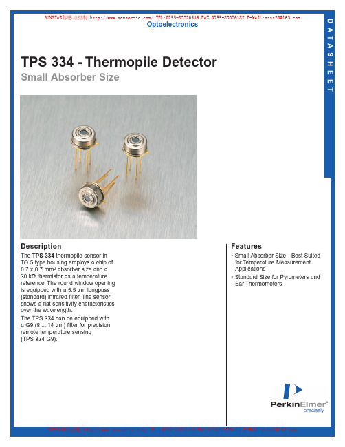
TPS 334 - Thermopile Detector Small Absorber Size D A T A S H E E TDescriptionThe TPS 334thermopile sensor in TO 5 type housing employs a chip of 0.7 x 0.7 mm2absorber size and a 30 kΩthermistor as a temperature reference.The round window opening is equipped with a 5.5 µm longpass (standard) infrared filter.The sensor shows a flat sensitivity characteristics over the wavelength.The TPS 334 can be equipped with a G9 (8 ...14 µm) filter for precision remote temperature sensing(TPS 334 G9).OptoelectronicsFeatures• Small Absorber Size - Best Suitedfor T emperature MeasurementApplications• Standard Size for Pyrometers andEar ThermometersSUNSTAR传感与控制/TEL:0755-********FAX:0755-********E-MAIL:************** SUNSTAR自动化/TEL:0755-********FAX:0755-********E-MAIL:**************TPS 334 - Thermopile Detector Small Absorber Siz e Page 2© 2003 PerkinElmer, Inc.All rights reserved.PerkinElmer, the PerkinElmer logo and the stylized “P”are trademarks of PerkinElmer, Inc.DS447-Rev A-0503*******************************************************************/optoelectronicsAll values are nominal;specifications subject to change without notice.North America:PerkinElmer Optoelectronics 16800 Trans-Canada HighwayKirkland, Quebec J7V 8P7 Canada Toll Free:(877) 734-OPTO (6786)Phone:+1-450-424-3300Fax:+1-450-424-3411Europe:PerkinElmer Optoelectronics Wenzel-Jaksch-Str.31D-65199 Wiesbaden, Germany Phone:+49-611-492-430Fax:+49-611-492-165Asia:PerkinElmer Optoelectronics 47 Ayer Rajah Crescent #06-12Singapore 139947Phone:+65-6770-4366Fax:+65-6775-1008Figure 5.Bottom ViewParameter Typical Units Condition Sensitive area 0.7 x 0.7mm 2absorbing area Window size 2.5mm diameterDC sensitivity 35V/W 500K BB 5 ...14µmResistance 75k ΩNoise 38nV/√Hz r.m.s.300K NEP 1.2nW/√Hz 500K BB 5 ...14µm D*0.6 x 108cm √Hz/W 500K BB 5 ...14µm TC of sensitivity 0.02%/K TC of resistance 0.02%/K Time constant 25ms Operating temperature -40 to 100°C non permanent Storage temperature -40 to 100°C non permanent Thermistor resistance30k Ω25°C beta3964K 25°C/100°C Field of view60°at 50% points Table 1.TPS 334Figure 1.Package DrawingFigure 4.Top View Package Dimension Figure 2.Figure 3.SUNSTAR传感与控制/TEL:0755-********FAX:0755-********E-MAIL:**************SUNSTAR自动化/TEL:0755-********FAX:0755-********E-MAIL:**************R i g h t f o r m o d i f i c a t i o n r e s e r v e d / W S /, 21.5.2001D A T A S HE E TThermopile Detector TPS 334Small absorber size best suited for temperature measurement applicationsStandard type for pyrometers and ear thermometersThe TPS 334 thermopile sensor in TO 5 type housing employs a chip of 0.7 x 0.7 mm 2 absorber size and a 30 k V thermistor as temperature reference.The round window opening is equipped with a 5.5 m m longpass (standard)inf rared f ilter. The sensor shows a f lat sensitivity characteristics over the wavelength.The TPS 334 can be equipped with a G9 (8..14 m m) filter for precision remotetemperature sensing (TPS 334 G9).R e l a t i v e s i g n a l o u t p u tFrequency in Hz-100-80-60-40-2002040608010020406080100TPS 334N o r m a l i z e d s i g n a l i n p e r c e n tAngle of incidence in degreesr e t e m a r a P la c i p y t st i n u no i t i d n o c a e r a e v i t i s n e S e z i s w o d n i W y t i v i t i s n e s C D e c n a t s i s e R e s i o N P E N *D y t i v i t i s n e s f o C T e c n a t s i s e r f o C T t n a t s n o c e m i T e r u t a r e p m e t e g a r o t S er u t a r e p m e t g n i t a r e p O r o t s i m r e h T e c n a t s i s e r at e b we i vf o d l e i F Thermopile Infrared DetectorspLighting | Imaging | TelecomS P T 4337.0x 7.0m m 2ae r a g n i b r o s b a 5.2m m r e t e m a i d 53W /V mµ41...5B B K 00557k W 83/V n Öz H ,K 003.s .m .r 2.1/W n ÖzH mµ41...5B B K 0056.0x 018m c ÖW /z H mµ41...5B B K 00520.0/%K 20.0K /%52s m 04-001C °t n e n a m r e p n o n 04-001C °tn e n a m r e p n o n 03k W C °524693K C °001/C °5206°st n i o p %05t a SUNSTAR传感与控制/TEL:0755-********FAX:0755-********E-MAIL:**************Product SpecificationS p e c i f i c a t i o nPerkinElmer Optoelectronics GmbH Wenzel-Jaksch-Straße 31 65199 Wiesbaden, Germany Phone: +49 (6 11) 4 92-0 Fax: +49 (6 11) 4 92-1 77 Product Picture:Product Name:Device Type:Part Number:TPS334-L5.5Thermopile Sensor96383238Rev. No.Date PagesRevision RecordDrawnChecked00 04DEC2001 10Initial ReleaseMSDrawn Mischa SchulzeDate 04DEC2001 Checked DateApproved DateReleasedDateCustomer:Reference No.:First Used:ReleasedDateTABLE OF CONTENTS1 SCOPE (3)2 GENERAL CHARACTERISTICS (3)MAXIMUM RATINGS (3)2.1 ABSOLUTE2.2 ELECTRICAL PARAMETER (3)2.2.1 Thermopile (3)2.2.2 Temperature Reference (4)REQUIREMENTS (4)2.3 HANDLING3 TYPE CHARACTERISTICS (4)CHARACTERISTICS (4)3.1 DESIGNCHARACTERISTICS (5)3.2 ELECTRICAL3.2.1 Thermopile (5)3.2.2 Thermistor (5)CHARACTERISTICS (6)3.3 OPTICAL3.3.1 Parameter (6)3.3.2 Sample Curve (6)CHARACTERISTICS (7)3.4 FILTER3.4.1 Sample Curve (7)3.5 MECHANICALDRAWING (8)4 QUALITY (8)4.1 QUALITY SYSTEM (8)ACCEPTANCE TEST (9)4.2 LOTConditions (9)4.2.1 TestParameter (9)4.2.2 Test4.2.3 Test Level at the End Test (9)4.2.4 Test Level at the Quality Test (9)4.3 REFERENCEDDOCUMENTS (9)4.4 LIABILITY POLICY (9)1 SCOPEThe HEIMANN thermopile sensor consists of a series of thermoelements, forming a sensitive area covered by an IR-absorbing material. The sensor is hermetically sealed into a metal housing. The size of the housing is similar to a TO-package with a window opening. The window is equipped with an IR-transmissible filter. An additional temperature reference sensor can be installed in the sensor housing. The thermopile sensor exhibits an almost white noise, comparable to an ohmic resistance. The thermopile output signal is direct proportional to incident radiation power largely independent from the wavelength. The frequency behaviour corresponds to a low pass characteristic.2 GENERAL CHARACTERISTICS2.1 ABSOLUTE MAXIMUM RATINGSParameter Symbol Limits Units Conditions Min Typ Max Ambient Temperature Range-40 100 °C Operation / Storage 2.2 ELECTRICAL PARAMETER2.2.1 ThermopileParameter Symb Limits Units Conditions Min Typ Max Sensistive Area 0.7*0.7 mm 2 Absorber Resistance R TP 50 75 100 k ΩResponsivity S V 55 V/W -,500K,1Hz 1)Time Constant 2)τ 25 ms Noise Voltage V RMS 35 nV/√Hz R.M.S.,25°C Noise Equivalent PowerNEP 0.64 nW/√Hz -,500K,1Hz 1) Detectivity D * 1.1*108 cm √Hz/W -,500K,1Hz 1)TC of Resistance 0 0.02 0.05 %/K TC of Responsivity -0.01 0.02 0.05 %/KTemperatureCoefficient Note 1: The values are defined without filter and optics.Note 2: The time constant can be measured as response to an object temperature jump (low to high or high to low) based on the following equations :Low to High : ττ=− −∆=∆t t e V V 1*max ⇒ −∆=∆e V V 11*maxHigh to Low : ττ=−∆=∆t teV V *max ⇒∆=∆e V V 1*max2.2.2 Temperature Reference Typ Thermistor 100k Ω Parameter Symbol Limits Units Conditions Min Typ Max Resistance R TH 28.5 30 30.9 k Ω At 25°C BETA-Value β 3944 3964 3984 K Defined at 25°C/100°C 2.3 HANDLING REQUIREMENTSStresses above the absolute maximum ratings may cause damages to the device. The sensor can be damaged by electrostatic discharges. Please take appropriateprecautions for the handling. The thermopile sensors can be damaged by electrostatic discharges. Please take appropriate precautions for the handling.Do not expose the sensor to aggressive detergents such as freon, trichlorethylen, etc. Windows may be cleaned with alcohol and cotton swab.Hand soldering and wave soldering may be applied by a maximum temperature of 300°C for a dwell time less than 10s. Avoid heat exposure to the top and the window of the detector. Reflow soldering is not recommended.3 TYPE CHARACTERISTICS3.1 DESIGN CHARACTERISTICSParameter Description Material Case TO5 Cap Round opening Alloy Nickel Header TO39 Steel with gold plating over Ni coating Optics Lense with focal length 5.5mm Silicon uncoated Leads (3 isolated +1 ground) pins Alloy with gold plating over Ni coating Filter G15 coating Silicon base with diff. coatings Temperature Reference Thermistor Ceramic with gold terminations Case Filling The sensor is hermetically sealed to withstand a gross leaktest according to MIL Std.883 method 1014c1.Dry nitrogenDevice Marking On Cap Side Manufacturer symbol + last 4 digits of the product number : 3 digits date code yww : PE### ###3.2 ELECTRICAL CHARACTERISTICS3.2.1 ThermopileLimits Units Conditions Parameter SymbMaxMinTypResistance R TP 50 75 100kΩ25°CTime Constant τ 25 70 ms 25°C Noise Voltage V RMS 40nV RMS/√Hz3.2.2 ThermistorT Rmin1 Rmin2 Rnom Rmax2 Rmax1°C Ω Ω Ω Ω Ω-40 844572 889932 907200 924468 951684-35 618414 651564 663000 674436 694326-30 457513 481993 489600 497207 511895-25 341771 360026 365100 370174 381127-20 257478 271207 274590 277973 286211-15 195682 206099 208350 210601 216851-10 149931 157900 159390 160880 165661-5 115788 121934 122910 123886 1275730 90086 94861 95490 96119 989845 70598 74335 74730 75125 7736710 55708 58653 58890 59127 6089415 44243 46578 46710 46842 4824320 35393 37259 37320 37381 3850125 28500 30000 30000 30000 3090030 22997 24210 24249 24288 2501635 18677 19663 19716 19769 2036040 15253 16059 16119 16179 1666245 12529 13191 13254 13317 1371450 10340 10888 10950 11012 1134155 8575 9030 9090 9150 942360 7145 7524 7581 7638 786665 5983 6300 6354 6408 659870 5032 5299 5349 5399 555975 4252 4478 4524 4570 470680 3606 3798 3840 3882 399785 3071 3235 3273 3311 341090 2624 2764 2799 2834 291895 2253 2373 2405 2437 2509100 1940 2044 2073 2102 2164Rmin1 : Minimum Thermistor Resistance resulting from the Total Tolerance Rmin2 : Minimum Thermistor Resistance resulting from the BETA-Tolerance Rnom : Typical Thermistor ResistanceRmax1: Maximum Thermistor Resistance resulting from the Total Tolerance Rmax2:Maximum Thermistor Resistance resulting from the BETA-Tolerance3.3 OPTICAL CHARACTERISTICS 3.3.1 ParameterTPS3x4-L5.5Parameter Limits Units Conditions Min Typ Max Field of View 7 10 degree At 50% target signal Optical Axis 0 ±2 degree 3.3.2 Sample Curve233437degrees [癩癩Field of View Measurement with a Thermopile module equipped with a 5,5mm-lens and a Antireflex Inlay3.4 FILTER CHARACTERISTICS 3.4.1 Sample Curve0102030405060708090100246810121416182022Wavelength [祄]T r a n s m i s s i o n [%]3.5 MECHANICAL DRAWING4 QUALITY4.1 QUALITY SYSTEMPerkinElmer Optoelectronics is an ISO 9001 certified manufacturer. All materials are checked according to specifications and final goods meet the specified tests.4.2 LOT ACCEPTANCE TEST4.2.1 Test ConditionsTypical ambient temperature 25°C4.2.2 Test ParameterConditionsLimits UnitsParameter SymbolMaxMinTypResistance TPS R TP50 75 100 kΩRT (room temperature)Resistance TH R TH20 30 40 kΩRT4.2.3 Test Level at the End TestLot conformance to specification of products delivered in volume production is checked bymeans of following tests (manufacturing) :Test Conditions Level Thermopile resistance Acc. to the test parameters, tolerance check 100%Thermistor resistance Acc. to the test parameters, functional check 100%4.2.4 Test Level at the Quality TestLot conformance to specification of products delivered in volume production is checked bymeans of following tests (quality) :Test Conditions Level Thermopile resistance Acc. to the test parameters, tolerance check AQL0.1Thermistor resistance Acc. to the test parameters, functional check AQL0.14.3 REFERENCED DOCUMENTSThe referenced documents form a part of this drawing. The revision level of these referenced documents unless defined shall be that which is in effect on the date of the purchase order.4.4 LIABILITY POLICYChanges or modifications at the product which havn't influence to the performance and/orquality of the device havn't to be announced to said customer in advance or approved by said customer. Customers are advised to consult with PerkinElmer Optoelectronics salesrepresentatives before ordering. Customers considering the use of PerkinElmerOptoelectronics thermopile devices in special applications where failure or abnormalwhere extremely high levels of reliability are demanded, are requested to consult with PerkinElmer Optoelectronics sales representatives before such use. The company will not be responsible for damage arising from such use without prior approval.As any semiconductor device, thermopile sensors or modules have inherently a certain rate of failure. It is therefore necessary to protect against injury, damage or loss from such failures by incorporating safety design measures into the equipment.TECHNICAL DATA THERMOPILE SENSORS O N L Y F O R I N F O R M A T I O NTPS 334-L10.6 / Preliminary S U B J E C T T O C H A N G E DESCRIPTIONThe sensor type TPS334-L10.6 consists of a series of thermoelements, forming a sensitive area of 0.7*0.7mm². The sensor is hermetically sealed into a metal housing. The size of the housing is similar to TO-5. The window is equipped with a lens optics based on silicon. The TPS334-L10.6 is assembled with an additional thermistor temperature reference. The thermopile sensor exhibits an almost white noise, comparable to an ohmic resistance. The thermopile output signal is directly proportional to incident radiation power largely independent from the wavelength. The frequency behaviour corresponds to a low pass characteristic.GENERAL DATAConditionsUnitParameterValueThermopilesmm²typicalabsorber,0.7*0.7SensitiveAreafilter or optics,500K,1Hz,typicalwithout55V/WResponsivity75kΩtypicalResistancenV/√Hz r.m.s.,25°C,typical35VoltageNoisenW/√Hz without filter or optics,500K,1Hz,typicalNEP0.581.2*108cm√Hz/W without filter or optics,500K,1Hz,typicalDetectivitymstypical25TimeConstantTC of Resistance <0.1 %/K%/K0.02typicalResponsivityTCofThermistor Temperature ReferencekΩdefined at 25°C30ResistanceResistance Tolerance +3 / -5 % defined at 25°CK defined3964at25°C/100°CValueBETA-BETA -Tolerance ±1 % for the total range of operation temperature/storageoperationTemperature Range -40..100 °CHERMETIC SEALThe Thermopile sensor is hermetically sealed to withstand a gross leaktest according toMIL Std.883 method 1014c1. The sensor is sealed with dry nitrogen.SOLDERINGHand soldering and wave soldering may be applied by a maximum temperature of 260°C for a dwell time less than 10s. Avoid heat exposure to the top and the window of the detector. Reflow soldering is not recommended. QUALITYHEIMANN is a ISO 9001 certified manufacturer with established SPC and TQM. All materials are checked according to specifications and final goods meet the specified tests.HANDLINGDo not expose the sensors to aggressive detergents such as freon, trichlorethylen, etc. Windows may be cleaned with alcohol and cotton swab.CAUTIONThe thermopile sensors can be damaged by electrostatic discharges. Please take appropriate precautions for the handling.TECHNICAL DATA THERMOPILE SENSORS O N L Y F O R I N F O R M A T I O N TPS 334-L10.6 / Preliminary S U B J E C T T O C H A N G E DIMENSIONS AND CONNECTIONSTECHNICAL DATA THERMOPILE SENSORS O N L Y F O R I N F O R M A T I O N TPS 334-L10.6 / Preliminary S U B J E C T T O C H A N G E FIELD OF VIEWTECHNICAL DATA THERMOPILE SENSORS O N L Y F O R I N F O R M A T I O N TPS 334-L10.6 / Preliminary S U B J E C T T O C H A N G E THERMISTOR REFERENCE DATAT Rmin1 Rmin2 Rnom Rmax2 Rmax1 ∆Tmin1 ∆Tmin2 ∆Tmax2 ∆Tmax1°C Ω Ω Ω Ω Ω °C °C °C °C-40 808655 854015 907200 960385 987601 -1.74 -0.94 0.94 1.42-35 594742 627892 663000 698108 717998 -1.67 -0.86 0.86 1.35-30 441842 466322 489600 512878 527566 -1.63 -0.8 0.8 1.29-25 331372 349627 365100 380573 391526 -1.6 -0.74 0.74 1.26-20 250577 264307 274590 284873 293111 -1.58 -0.68 0.68 1.22-15 191113 201531 208350 215169 221420 -1.54 -0.61 0.61 1.17-10 146923 154893 159390 163887 168669 -1.49 -0.54 0.54 1.11-5 113827 119973 122910 125847 129535 -1.43 -0.47 0.47 1.040 88824 93599 95490 97381 100246 -1.37 -0.39 0.39 0.985 69841 73578 74730 75882 78124 -1.33 -0.32 0.32 0.9310 55297 58241 58890 59539 61305 -1.34 -0.25 0.25 0.915 44016 46352 46710 47068 48470 -1.38 -0.19 0.19 0.9120 35330 37196 37320 37444 38563 -1.24 -0.08 0.08 0.7825 28500 30000 30000 30000 30900 -1.17 0 0 0.730 22930 24143 24250 24357 25085 -1.3 -0.11 0.11 0.8235 18570 19556 19720 19884 20475 -1.42 -0.21 0.21 0.9440 15118 15924 16120 16316 16799 -1.56 -0.31 0.31 1.0645 12383 13045 13250 13455 13852 -1.7 -0.41 0.41 1.1850 10197 10744 10950 11156 11484 -1.84 -0.51 0.51 1.3155 8434 8888 9090 9292 9564 -1.99 -0.62 0.62 1.4460 7010 7389 7581 7773 8001 -2.13 -0.72 0.72 1.5765 5858 6176 6354 6532 6723 -2.25 -0.81 0.81 1.6870 4916 5183 5349 5515 5675 -2.38 -0.92 0.92 1.7975 4146 4372 4524 4676 4812 -2.5 -1.01 1.01 1.980 3508 3700 3840 3980 4095 -2.63 -1.11 1.11 2.0285 2981 3145 3273 3401 3500 -2.77 -1.22 1.22 2.1590 2542 2682 2799 2916 3000 -2.93 -1.34 1.34 2.2995 2179 2299 2405 2511 2583 -3.11 -1.46 1.46 2.45100 1873 1977 2073 2169 2231 -3.34 -1.6 1.6 2.64TECHNICAL DATA THERMOPILE SENSORS O N L Y F O R I N F O R M A T I O NTPS 334-L10.6 / Preliminary S U B J E C T T O C H A N G ETYPICAL FILTER CHARACTERSITICS0102030405060708090100246810121416182022Wavelength [祄]T r a n s m i s s i o n [%]thermophysica minima THERMOELECTRIC INFRARED SENSORS (THERMOPILES) FOR REMOTE TEMPERATURE MEASUREMENTS; PYROMETRYAbstractNowadays, there are thermopile sensors available, which allow remotetemperature sensing at quite low overall system costs. The sensor does notrequire any cooling and – dependent on the measurement range – canreach a typical accuracy of ±1 K. For narrow temperature ranges as e.g. inbody temperature measurement, a precision of 0.1 K is possible.PerkinElmer Optoelectronics has developed a series of thermopile typesadapted for various applications. Available standard devices are:! sensors for ear thermometers to sense body temperature,! sensors with focussing optics and signal processing electronics (on circuit board or integrated in sensor housing) for object temperature control in microwave ovens, hair dryers, cookers, etc.,! sensor arrays with integrated multiplexer and amplifier for pattern recognition in position control ine.g. automobiles (airbag safety), room sensing by position and direction control of humans, etc.! sensors with infrared bandpass filters for gas detection by infrared absorption. This subject is cov-ered by a separate article [1].The achievement of a good performance of thermopile devices requires a minimum of knowledge on infrared technology and thermal management of thermoelectric devices. This article therefore aims at the necessary basics for a correct implementation.1 Introduction (2)1.1 Photonic detectors (2)1.2 Pyroelectric sensors (2)1.3 Thermopile sensors (3)2 Thermopiles by modern microsystem technology (4)3 Characteristic figures of thermopiles (5)4 Temperature measurements by thermopiles (7)4.1 Calibrating a thermopile for temperature measurements (8)4.2 Factors disturbing the accuracy (8)4.3 Practice of ambient temperature compensation (9)4.4 On the emission coefficient (10)5 Frequently asked questions (10)6 Literature (12)thermophysica minima : Thermopiles for pyrometry1 IntroductionEvery object emits radiation which is largely controlled by the object’s temperature. For an object that has “no color”, which means, no wavelength is selectively emitted or absorbed, the radiation spectrum is completely determined by the temperature alone. In this case, one speaks of a “black body”. The spectral radiation character-istics of a black body can be theoretically calcu-lated. Figure 1 shows them for selected tempera-tures.101031061091012S p e c i f i c s p e c t r a l e m i s s i o n i n W /(m 2µm s r )Wavelength in µmFigure 1: Spectral radiation characteristics of a “black body” at different temperatures (Planck’s radiation law). It is to be noted that the curves never intersect, which means that the radiation intensity at every wavelength is a strict function of the temperature. By measuring the intensity of the radiation one can there-fore determine the object’s temperature.With rising temperature, the intensity at every wavelength of the radiation spectrum increases as well. This means that one can remotely determine the temperature of an object by measuring its radiated power. Such a measurement can, for example, be carried out by using your eyes. The human eye is sensitive for radiation in the range from 0.38 to 0.75 µm. This region – it is naturally called the “visible spectrum” – is marked in Fig-ure 1. If the temperature of an object exceeds 400 °C (700 K), it will emit a remarkable portion of radiation at the red end of the visible region. It will start to glow in a dark red color, an effect well known from electrically heated stoves. When further increasing the temperature – lets say to 1000 °C (1300 K), the glowing will not only become more intensive, but also its color will change to light red, because there are now green and yellow portions added. Radiation from an object with a temperature of 6000 K will ap-temperature of the sun and our eyes are adapted to “detect” this radiation as white light.1.1 Photonic detectorsIf the measured body has a temperature lower than 400 °C, one needs a radiation detector which is sensitive to a much longer wavelength than those of the visible spectrum. A detector is needed, which is sensitive to the infrared region (also called heat radiation) around 10 µm wave-length. There are different sensors available, which are capable for accurately detecting and measuring heat radiation in the 3 to 20 µm infra-red (IR) wavelength region. The most common IR detectors employed during the past decades are based on semiconductors, in which the inci-dent IR radiation induces a change in electrical conductivity, which can easily be measured and used as the sensing signal for the incident power. Such photonic detector systems offer a great ac-curacy and sensitivity to IR radiation. The needed semiconductors and thermal and electrical sys-tems, though, are very expensive.1.2 Pyroelectric sensorsFor a long time the high cost issue posed severe constraints on the development of IR systems for the consumer market. This could only be over-come by another class of detectors. A type of sensor capable to detect IR radiation with a good accuracy and at the same time being available at low cost are the so-called pyroelectric sensors. Here, the heat radiation collected by the pyroelectric material generates a static voltage signal across the crystalline material. Under constant illumination, however, the signal declines, which makes a periodical refresh necessary. This is usually achieved by aThermal factsThere are people who think that an infrared temperature measurement needs to send out some sort of radiation which may be harmful.Therefore they hesitate to use an ear ther-mometer, for example.It thus has to be emphasized that a radiative temperature measurement is an entirely pas-sive method – it measures only the natural heat which is sent out by every object.usually achieved by a mechanical chopper in front of the detector.Pyroelectric detectors are applicable for mass production. They have found their way into theconsumer market through applications in burglar alarm systems and automatic light switches. Here, the detector senses the IR radiation from approaching persons. In this case, no chopper is needed, because an optics focuses the radiation from the moving persons alternately onto two detector crystals with opposite polarity. This generates a difference signal, which drives a switch or an alarm. The advantage of pyroelectric detectors is in detecting moving objects and at the same time suppressing quasi-static signals as from furnaces and other heat sources, which vary only slowly in time. On the other hand, for static temperature measurements one still needs a rela-tively expensive setup which includes mechanical parts.1.3 ThermopilesensorsRecently, an over 150 year old method to meas-ure infrared radiation is revived: The utilization of thermocouples. A thermocouple consists of two different materials which are connected at one end, while the other two ends are attached to a voltage meter (cf. Figure 2a). If there is a tem-perature difference between the common junction and the voltmeter ends, a so-called thermovoltage is shown by the meter. The magnitude of the voltage is a function of the temperature differ-ence, but also dependent on the nature of the two employed materials.If we now attach an absorber to the junction, and place it into the IR radiation coming from an object, the absorber will collect the incident heat (Figure 2b). We can simply say that the absorber and thus the thermocouple junction will warm up due to the incident radiation. After a short while, the temperature difference between the (warm) junction and the (colder) reference ends will sta-bilize. The thermocouple material in turn con-verts the temperature difference into a voltage shown by the voltmeter. Thus, the voltmeter reading is a direct measure for the object tem-perature. This method is principally simple, does not need any mechanics, and can accurately sense static signals. Like the pyroelectric detectors, a thermopile sensor generates the measurement signal by itself, not requiring any current source.heatradiation(a)(b) Figure 2: Thermocouple principle. (a) Two dissimilar conductors form a thermocouple. A temperature dif-ference over the couple generates an electrical voltage.(b) The needed temperature difference emerges if heat is absorbed by the thermocouple junction and led to a heat sink. The developing voltage is proportional to the amount of flowing heat.Classically, several ten macroscopic wire ther-moelements were connected in series in order to increase the generated voltage and to make the system more sensitive. The materials employed were mostly antimony and bismuth, as they ex-hibit a large thermovoltage. The resulting system was called a thermopile, because it was indeed a pile, made of a large heavy block. Figure 3 shows an original sketch of such an instrument after N. Nobili (1835). Due to the large thermal masses it was very slow in following signal changes. As can be imagined, these instruments were origi-nally only applicable for laboratory work.Figure 3: In series connected thermocouples made of antimony and bismuth (a) form a thermopile (b). After N. Nobili (1835).Nowadays, modern semiconductor technology makes it possible to produce thermopile sensors consisting of hundreds of thermocouples on an area of several square millimeters. Such a sensor is extremely sensitive, shows a very fast response。
电容触摸按键代替机械按键FTC334C
影响芯片正常工作。
— 环境温度湿度变化自动适应,环境缓慢适应技术的应用,使得芯片无限长时间连续工作不
会出现灵敏度差异。
— 可调灵敏度,可以通过外接电容容量来调整灵敏度以适应不同的设计。
— 提供二进制编码直接输出接口,方便用户系统对接。
— 上电快速初始化,在300mS左右内芯片就可以检测好环境参数包括自动适应,按键检测功
扰和提升抗ESD静电能力
--
电源负端
输入 输出
输入选项口,内部有上拉电阻 悬空:输出模式为高电平,可多按键同时输出 接地:输出模式为高阻抗,只允许单按键输出 触摸信号输出口,对应K6-K5 按键有效时为低电平,无按键时为高电平或高阻抗
--
电源正端
-输出
接基准电容Cs负端,Cs电容正端接VDD Cs电容须使用5%精度涤纶插件电容、10%高精度的 NPO材质或X7R材质贴片电容 触摸信号输出口,对应K4-K1 按键有效时为低电平,无按键时为高电平或高阻抗
U1
1 2 3 4 5 6 7 8
K1 K2 K3 K4 K5 K6 G ND S1
Q1 Q2 Q3 Q4 CAPN VDD Q5 Q6
16 15 14 13 12 11 10 9
FTC334C
V DD
R18 47
CS1
CS2
153
*
C3
+ C4
104
100uF
※ 请按照K1,K2,..K6的顺序来选用按键输入,后面不用的按键口接地,K1、K2禁止接地。
16 Q1 15 Q2 14 Q3 13 Q4 12 CAPN 11 VDD 10 Q5 9 Q6
SOP16L
管脚描述:
编 号 管脚名称
FTC334E触摸IC

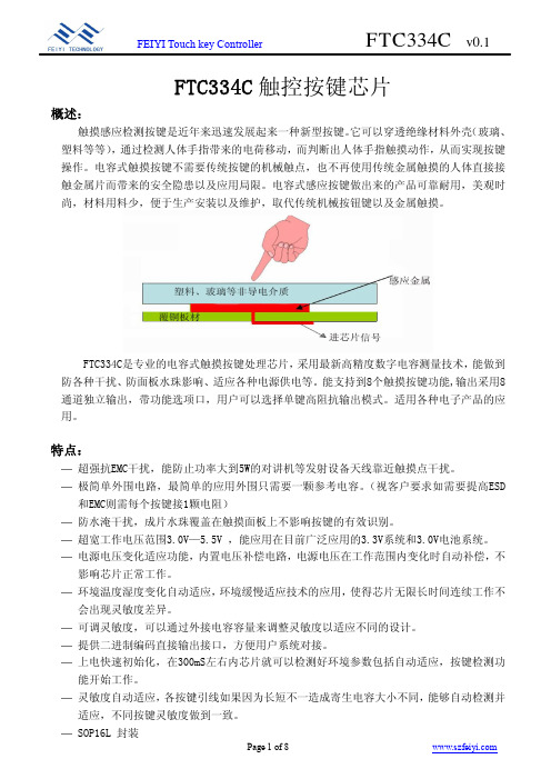
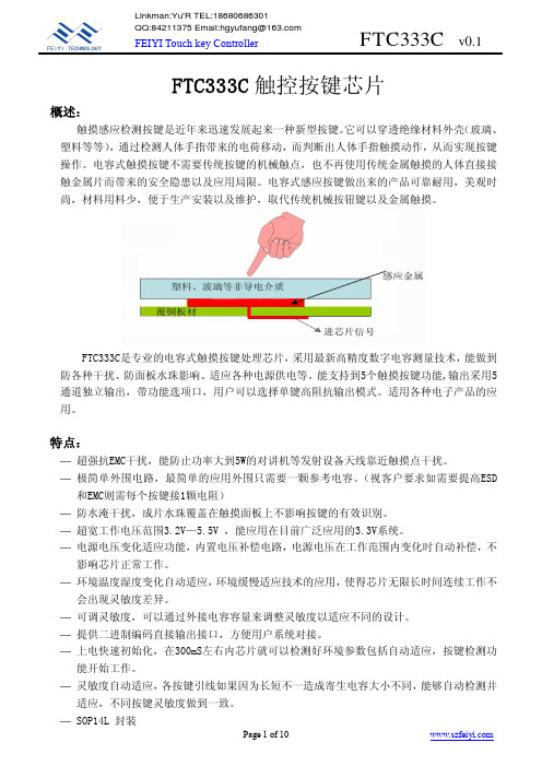
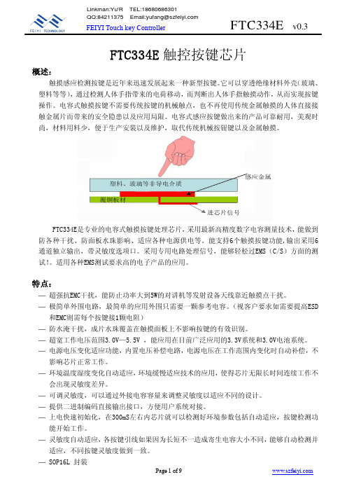
F T C334E触控按键芯片概述:触摸感应检测按键是近年来迅速发展起来一种新型按键。
它可以穿透绝缘材料外壳(玻璃、塑料等等),通过检测人体手指带来的电荷移动,而判断出人体手指触摸动作,从而实现按键操作。
电容式触摸按键不需要传统按键的机械触点,也不再使用传统金属触摸的人体直接接触金属片而带来的安全隐患以及应用局限。
电容式感应按键做出来的产品可靠耐用,美观时尚,材料用料少,便于生产安装以及维护,取代传统机械按钮键以及金属触摸。
F T C334E是专业的电容式触摸按键处理芯片,采用最新高精度数字电容测量技术,能做到防各种干扰、防面板水珠影响、适应各种电源供电等。
能支持6个触摸按键功能,输出采用6通道独立输出,带灵敏度选项口。
采用专用电路处理信号,能够轻松过E M S(C/S)方面的测试!。
适用各种E M S测试要求高的电子产品的应用。
特点:—超强抗E M C干扰,能防止功率大到5W的对讲机等发射设备天线靠近触摸点干扰。
—极简单外围电路,最简单的应用外围只需要一颗参考电容。
(视客户要求如需要提高E S D 和E M C则需每个按键接1颗电阻)—防水淹干扰,成片水珠覆盖在触摸面板上不影响按键的有效识别。
—超宽工作电压范围3.0V—5.5V,能应用在目前广泛应用的3.3V系统和3.0V电池系统。
—电源电压变化适应功能,内置电压补偿电路,电源电压在工作范围内变化时自动补偿,不影响芯片正常工作。
—环境温度湿度变化自动适应,环境缓慢适应技术的应用,使得芯片无限长时间连续工作不会出现灵敏度差异。
—可调灵敏度,可以通过外接电容容量来调整灵敏度以适应不同的设计。
—提供二进制编码直接输出接口,方便用户系统对接。
—上电快速初始化,在300m S左右内芯片就可以检测好环境参数包括自动适应,按键检测功能开始工作。
—灵敏度自动适应,各按键引线如果因为长短不一造成寄生电容大小不同,能够自动检测并适应,不同按键灵敏度做到一致。
—S O P16L封装管脚封装:管脚描述:编 号 管脚名称 类 型 功 能 描 述1-6K1-K6输入/输出 触摸信号接入口,空闲时为低电平一般使用时串联470欧姆-1K电阻,能有效防止R F干扰和提升抗E S D静电能力 7G N D--电源负端8S1输入 输入选项口,内部有上拉电阻 悬空:芯片为高灵敏度模式 接地:芯片为低灵敏度模式9-10Q6-Q5输出 触摸信号输出口,对应K6-K5按键有效时为低电平,无按键时为高电平11V D D--电源正端系统中使用1628等芯片驱动数码管时建议一定要给触摸芯片电源加R C滤波!12C A P N--接基准电容C s负端,C s电容正端接V D DC s电容须使用5%精度涤纶插件电容、10%高精度的N P O材质或X7R材质贴片电容13-16Q4-Q1输出 触摸信号输出口,对应K4-K1按键有效时为低电平,无按键时为高电平K1K2K3K4K5K6GNDS1SOP16L应用图例:※ 请按照K1,K2,..K6的顺序来选用按键输入,后面不用的按键口接地,K1、K2禁止接地。
飞翼触摸芯片FTC334B-V0

功能描述:
1、按键检测: 芯片内置电容测量电路以及高精度逻辑运算器对各按键输入口对地的电容量进行测量
4.从触摸感应PAD或者感应弹簧片到IC管脚的连线长度尽量不绕太远,尽量避免连线之间的耦 合电容,也要避免与其他高频信号线有耦合电容。
5.灵敏度与触摸感应PAD或者感应弹簧片面积成正比,与外壳厚度成反比。根据外壳厚度和尺 寸选择合适的触摸面积。一般玻璃外壳比塑料更高穿透力。
6.触摸感应PAD与PAD之间应该尽量留一定的间距,以保证手指头触摸时不会覆盖到2个PAD,同 时也能防止PAD寄生电容过大。
7.因为空气介电常数太小,并且受湿度影响,所以介质中最好不要有空气。触摸PAD或者感应 弹簧片与绝缘外壳应压合紧密,保持平整,以免有气隙产生。外壳与PAD之间可以采用非导 电胶进行粘和,例如压克力胶3MHBM系列。
8.基准电容Cs电容建议使用温度系数小精度高的电容,以免造成灵敏度不一致或随温度变化而 变化。一般插件电容建议5%精度涤纶电容,如需贴片电容则建议使用10%或更高精度的NPO 材质电容或X7R材质电容。
止意外情况芯片输出锁死。按键锁死是指在非正常使用或者非正常条件下,环境的突然改变 造成按键输出信号一直存在而无法消除的情况!
4、按键优先: FTC334B芯片同时检测到3个以上按键非组合按键有效时,输出为无按键状态。
5、S1选项: S1灵敏度调节选择输入选项口,内部有上拉电阻。悬空灵敏度高,接地灵敏度低。在调
输出 电压值: 5.0V
奥伟斯为您提供万代触摸感应芯片应用方案

奥伟斯科技为您提供WINCOM电容式触摸控制IC万代触摸感应芯片应用设计解决方案!!!公司以专业的集成电路设计技术和高效的市场拓展能力为核心,专注于电容式触摸感应IC的设计和销售, 为电器产品提供美观、坚固、无磨损、无限寿命、绝对安全、低成本的人机界面解决方案。
公司自主研发的WTC系列触摸感应IC内部集成了高精度电容测量电路和高效的处理器,可以透过0-20mm的绝缘面板准确地侦测到手指对按键的有效触摸并输出数据,非常容易与单片机接口实现各种电器产品的触摸感应控制,产品具有优良的防水和抗干扰性能,在温度和潮湿度大范围波动的环境下长期稳定工作。
基于高性能、高品质、多品种的产品和专业的服务, WTC系列触摸感应IC已经覆盖家用电器、计算机、手持设备、工业控制、安防设备、军用产品等几乎所有应用领域。
为响应广大用户对提高触摸控制集成度和降低成本的要求,我公司成功研发出WM系列触控MCU,WM系列触控MCU内建了万代历时十年上亿出货量证明其高度稳定和高度可靠的触摸感应核心,为用户提供品质一流,使用灵活的可编程触摸感应单片机,该系列产品已于2014年7月正式推出,并与2014年10月量产出货。
WTC02SPWTC02DWTC6104BSIWTC6104BSI-LWTC6106BSIWTC6106BSI-LWTC6106BSI-MWTC6208BSIWTC6208BSI-MWTC6208D1MWTC6506D32WTC6508BSIWTC6508BSI-MWTC1006BSIWTC1006BSI-MWTC1008BSIWTC1008BSI-MWTC6212MLWTC6212ML-5WTC6212ML-10WTC6212BSIWTC6212BSI-LWTC6216BSIWTC6216BSI-LWTC6216ASI WTC6312ML WTC6312ML-2 WTC6312ML-2F WTC6312ML-10 WTC6312ML-10F WTC6312BSI WTC6312BSW WTC6316BSI WTC6316BSI-L WTC6320DSI WTC6320DSI-L WTC62K1R WTC64K1R WTC66K1R WTC68K1R WTC6401RSI WTC6601RSI WTC801SPI WTC801SPI-L WTC7508DSI WTC401SPI WTC40-1SPI-L WTC708AWM708A16N WM708A24A WM708A24W WM708A28A WTC708BWM708B16N WM708B24A WM708B24W WM708B28A WTC708CWM708C24A WM708C24W WM708C28A WTC7514DSI WTC7514DSW WM708DWM708D16N WM708D24A WM708D24W WM708D28AWTC1006BSI 系列触摸感应 IC 是为实现人体触摸界面而设计的集成电路。
FTC334B-V0

F T C334B触控按键芯片概述:触摸感应检测按键是近年来迅速发展起来一种新型按键。
它可以穿透绝缘材料外壳(玻璃、塑料等等),通过检测人体手指带来的电荷移动,而判断出人体手指触摸动作,从而实现按键操作。
电容式触摸按键不需要传统按键的机械触点,也不再使用传统金属触摸的人体直接接触金属片而带来的安全隐患以及应用局限。
电容式感应按键做出来的产品可靠耐用,美观时尚,材料用料少,便于生产安装以及维护,取代传统机械按钮键以及金属触摸。
F T C334B是专业的触摸按键处理芯片,采用最新高精度数字电容测量技术,能做到防辐射以及电源干扰、防面板水珠影响、适应各种电源供电等。
其最大能支持到8个触摸按键功能。
输出4位数二进制码,可以接电阻后做成模拟电压书。
带灵敏度选项脚,以及按键指示口。
适用家电等对抗干扰要求高的产品应用。
特点:—超强抗E M C干扰,能防止功率大到5W的对讲机等发射设备天线靠近触摸点干扰。
—极简单外围电路,最简单的应用外围只需要一颗参考电容。
(视客户要求如需要提高E S D 和E M C则需每个按键接1颗电阻)—防水淹干扰,成片水珠覆盖在触摸面板上不影响按键的有效识别。
—超宽工作电压范围3.0V—5.5V,能应用在目前广泛应用的3.3V系统和3.0V电池系统。
—电源电压变化适应功能,内置电压补偿电路,电源电压在工作范围内变化时自动补偿,不影响芯片正常工作。
—环境温度湿度变化自动适应,环境缓慢适应技术的应用,使得芯片无限长时间连续工作不会出现灵敏度差异。
—可调灵敏度,可以通过外接电容容量来调整灵敏度以适应不同的设计。
—提供二进制编码直接输出接口,方便用户系统对接。
—上电快速初始化,在300m S左右内芯片就可以检测好环境参数包括自动适应,按键检测功能开始工作。
—灵敏度自动适应,各按键引线如果因为长短不一造成寄生电容大小不同,能够自动检测并适应,不同按键灵敏度做到一致。
—S O P16L封装管脚封装:管脚描述:编 号 管脚名称 类 型 功 能 描 述1-4K 5-K 8 输入/输出 触摸盘电容信号输入口一般使用时串联470欧姆-1K 电阻,能有效防止R F 干扰和提升抗E S D 静电能力 5 D 3(K V ) 输出 二进制码输出D 3端;可做按键有效信号,当有效按键被检测到时输出低电平,所有按键均释放时为高电平 6 D 0 输出 二进制码输出D O端 7 G N D -- 电源负端8 S 1 输入 灵敏度调节选择输入选项口,内部有上拉电阻悬空灵敏度高,接地灵敏度低 9 D 1 输出 二进制码输出D 1端 10 D 2输出二进制码输出D 2端11V D D -- 电源正端系统中使用1628等芯片驱动数码管时建议一定要给触摸芯片电源加R C 滤波! 12C A P N -- 接基准电容C s 负端,C s 电容正端接VD DC s 电容须使用5%精度涤纶插件电容、10%高精度的N P O 材质或X 7R 材质贴片电容 13-16K 1-K 4 输入/输出 触摸盘电容信号输入口一般使用时串联470欧姆-1K 电阻,能有效防止R F 干扰和提升抗E S D 静电能力K5 K6 K7 K8 D3 D0 GND S1 SOP16L※ 请按照K1,K2,..K8的顺序来选用按键输入,后面不用的按键口接地。
FTC333F-V0

— 电源电压变化适应功能,内置电压补偿电路,电源电压在工作范围内变化时自动补偿,不
影响芯片正常工作。
— 环境温度湿度变化自动适应,环境缓慢适应技术的应用,使得芯片无限长时间连续工作不
会出现灵敏度差异。
— 可调灵敏度,可以通过外接电容容量来调整灵敏度以适应不同的设计。
— 提供扫描输出接口,方便用户系统对接显示驱动芯片1628。
Page 5 of 10
FEIYI Touch key Controller
FTC333F v0.2
K6 - - - 0 1 - 1 0 K7 - - - 0 1 - 1 1 K8 - - - 1 0 - 0 0 K1+K5 - - - 1 1 - 0 1 K2+K6 - - - 1 1 - 1 0 表中“-”表示该数据无意义
FEIYI Touch key Controller
FTC333F v0.2
综上所述,建议采用RC滤波后再给触摸IC供电。尤其是系统中有使用1628等驱动数码 管的产品应用中!
注意事项:
1.使用用双面PCB,可以在顶层使用圆形、方形等作为触摸感应PAD,从触摸感应PAD到IC管脚 的连线应该尽量走在触摸感应PAD的另外一面。同时连线应该尽量走细,不要绕远。使用单 面板则一般需要使用感应弹簧片。因为其侧面也能同手指头形成电场,使用感应弹簧片比使 用PCB上做触摸感应PAD能获得更高的灵敏度。
电源正端 系统中使用1628等芯片驱动数码管时建议一定要给 触摸芯片电源加RC滤波! 接基准电容Cs负端,Cs电容正端接VDD Cs电容须使用5%精度涤纶插件电容、10%高精度的 NPO材质或X7R材质贴片电容 触摸信号接入口,空闲时为高阻抗 一般使用时串联470欧姆-1K电阻,能有效防止RF干 扰和提升抗ESD静电能力
华诚科技触摸IC选项表
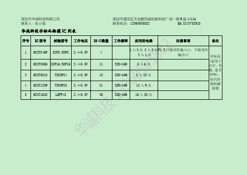
华诚科技非标品触摸 IC 列表
深圳市福田区天安数码城创新科技广场一期 B 座 1411A
联系电话:13360505882
QQ:3243702918
序号 IC 型号 封装型号 工作电压 IO 口数量 工作频率 应用的电路
注意事项
备注
1 HC8T046P DIP8/SOP8 2.4-5.5V
OSC=GND,LO1、LO2=0
OSC=VDD,LO1、LO2=1; 2.4-5.5V
OSC=GND,LO1、LO2=0
功能说明 同步功能(脉冲功能)
开关功能
备注
2.4-5.5V
4 种工作模式可选
1)OPT1=1,OPT2=1 对应:不带亮度记忆突明突暗的 LED 触 摸无级调光功能 2)OPT1=0,OPT2=1 对应:不带亮度记忆渐明渐暗的 LED 触 摸无级调光功能 3)OPT1=1,OPT2=0 对应:带亮度记忆渐明渐暗的 LED 触 摸无级调光功能 4)OPT1=0,OPT2=0 对应:LED 三段触摸调光功能
4
1 入 3 出 2 入 2 出 P1.5 只能用作输入口,不能用作
3入1出
输出口
非标品
2 HC8T0506 DIP16/SOP16 2.4-5.5V
11
32K-16M
5入6出
(适用于 台灯、车
载、蓝牙
3 HC8T0810 TSSOP24 2.4-5.5V
18
32K-16M
8 入 10 出
音响),
取代传
4 HC8T1209 TSSOP28 2.4-5.5V
21
32K-16Mຫໍສະໝຸດ 12 入 9 出统机械 按键
FTC333C 触摸芯片
Page 4 of 10
FEIYI Touch key Controller
FTC333C v0.1
八、电源要求: FTC系列的电压范围可以达到3.0V—5.5V,在此范围内IC可以都可以正常工作。但是
在每个测量周期内(10ms),IC电源电压值必须保证相对平滑稳定,否则会干扰到内部电容 测量的模拟电路。
2)触摸灵敏度与绝缘面板的厚度有关,同一介质的绝缘面板,厚度越薄灵敏度越高,
绝缘面板厚度越大,灵敏度越低。
3)触摸与按键感应盘的有效面积有关,面积越大,灵敏度越高,面积越小,灵敏度
越低。
在以上3个项目都固定的情况下,对芯片Cs电容容量进行调节也能获得不同的灵敏度。
芯片在运算的过程中需要采用Cs电容来做为基准参照,对Cs电容的调节能改变芯片运算,获
4.从触摸感应PAD或者感应弹簧片到IC管脚的连线长度尽量不绕太远,尽量避免连线之间的耦 合电容,也要避免与其他高频信号线有耦合电容。
5.灵敏度与触摸感应PAD或者感应弹簧片面积成正比,与外壳厚度成反比。根据外壳厚度和尺 寸选择合适的触摸面积。一般玻璃外壳比塑料更高穿透力。
6.触摸感应PAD与PAD之间应该尽量留一定的间距,以保证手指头触摸时不会覆盖到2个PAD,同 时也能防止PAD寄生电容过大。
手指远离触摸感应区域时,该按键输入口对地电容会恢复到原来值,同样当该变化量被持续
有效检测到超过60ms,芯片判断按键离开有效,对应输出端口会输出无按键信息。
2、灵敏度:
根据电容公式 C=εS/4πkd (ε为介质介电常数,S为电极面积,d为电极之间距离)
可知: 1)触摸灵敏度与绝缘面板的材质有关,介电常数越大,触摸感应灵敏度越高。
FTC334F-V0

3、高灵敏度选项: 在一些应用中,需要穿透较厚的玻璃(比如火锅桌内嵌电磁炉需要15mm以上厚度)或其
他比较难穿透的材料时,FTC334F可能将Cs电容调整到极限也无法满足灵敏度要求。 此时,FTC334F提供了一种提高灵敏度的功能选项:将K9接地,K10悬空,灵敏度提高约
1倍。需要注意的是:因为K9接地,此时FTC334F只能提供最多8个按键功能,K9、K10脚不再 具有触摸按键功能。
特点:
— 超强抗EMC干扰,能防止功率大到5W的对讲机等发射设备天线靠近触摸点干扰。
— 极简单外围电路,最简单的应用外围只需要一颗参考电容。(视客户要求如需要提高ESD
和EMC则需每个按键接1颗电阻)
— 防水淹干扰,成片水珠覆盖在触摸面板上不影响按键的有效识别。
— 超宽工作电压范围3.0V—5.5V,能应用在目前广泛应用的3.3V系统和3.0V电池系统。
4、按键异常抑制: 长按时间抑制,芯片检测到持续按键信号超过30S时,会判断为非法动作而复位,重新
进行系统环境初始化。 多按键抑制,芯片检测超过4个或更多按键输入端口同时有效按键信号时 ,会判断为非
法动作而复位,重新进行系统环境初始化。 以上按键抑制动作可以有效防止用户在安装、生产过程中造成输出锁住的情况,也能防
2、灵敏度: 根据电容公式 C=εS/4πkd (ε为介质介电常数,S为电极面积,d为电极之间距离)
可知: 1)触摸灵敏度与绝缘面板的材质有关,介电常数越大,触摸感应灵敏度越高。 2)触摸灵敏度与绝缘面板的厚度有关,同一介质的绝缘面板,厚度越薄灵敏度越高,
绝缘面板厚度越大,灵敏度越低。 3)触摸与按键感应盘的有效面积有关,面积越大,灵敏度越高,面积越小,灵敏度
用户读取数据则同读取1628机械按键的方式一样,只需要读按键数据1BYTE即可。以应 用图例接法中为例,无按键时,数据有效位都为0。具体数据如下表:
TC334_中文手册_F1V1.5
TC Serial touch sensor
Dimensions In Inches Page 5 of 6
TC334_DataSheet_F1V1.5
Min
Nom
Max
Min
Nom
Max
A
1.30
1.50
1.70
0.051
0.059
0.067
A1
0.06
0.16
0.26
0.002
0.006
0.010
PCB 版图注意事项
1. VCC 和 VSS 电源线要单独走线,不能和其它芯片(单片机和 LCD 驱动芯片等)共用电源走线。以免 使其它芯片的干扰信号通过电源线引到触摸芯片。
2. CP,CVREG,CSEN 三个电容必须靠近芯片放置。感应线上串联的 CX0~CX3 电阻,靠近芯片放置为宜。 3. 尽量大的铺地面积,可以提高抗干扰性。 4. 感应连线和感应焊盘优先布局。芯片靠近感应焊盘放置,感应连线直接引到感应焊盘(或弹簧焊 盘),不同按键的感应连线不需要长度一致。感应连线线宽尽量小。感应连线周围不能走其他电源线和信号 线。如果实在不能避免,其他走线要垂直跨过感应连线。感应焊盘之间至少留 5mm 间距,感应焊盘和铺地 之间距离大于 1.5mm。
额定值 *
工作温度 存储温度 电源电压 管脚最大电流 管脚电压 * 注意 超出额定值可能会导致芯片永久损坏
-40 ~ +85ºC -50 ~ +150ºC -0.3 ~ +6.5V ±20mA -0.3V ~ (Vcc+ 0.3) Volts
电气特性
TA = 25℃ 特性 工作电压 电流消耗
符号 Vcc Idd
O1 高阻 低电平 高阻 高阻 高阻
永嘉原厂抗干扰低功耗4键触摸芯片:VK36Q4 DFN10 触摸灵敏度高,体积小,抗干扰能力强
低功耗高抗干扰4键触摸触控芯片-VK36Q4,超小体积封装VK36Q4概述:VK36Q4具有4个触摸按键,可用来检测外部触摸按键上人手的触摸动作。
该芯片具有较高的集成度,仅需极少的外部组件便可实现触摸按键的检测。
提供了4路直接输出功能。
芯片内部采用特殊的集成电路,具有高电源电压抑制比,可减少按键检测错误的发生,此特性保证在不利环境条件的应用中芯片仍具有很高的可靠性。
此触摸芯片具有自动校准功能,低待机电流,抗电压波动等特性,为各种触摸按键+IO 输出的应用提供了一种简单而又有效的实现方法。
特点:(QT969)• 工作电压 2.4-5.5V•待机电流7uA/3.0V,14uA/5V•上电复位功能(POR)•低压复位功能(LVR)•许硕:188.9858.2398• Q:191.888.5898•触摸输出响应时间:工作模式 48mS 待机模式160mS• CMOS输出,低电平有效,支持多键•有效键最长输出16S•无触摸4S自动校准•专用脚接对地电容调节灵敏度(1-47nF)•各触摸通道单独接对地小电容微调灵敏度(0-50pF)•上电0.25S内为稳定时间,禁止触摸•封装 DFN10L(3.0mm x 3.0mm PP=0.5mm)标准触控IC-电池供电系列:VKD223EB --- 工作电压/电流:2.0V-5.5V/5uA-3V 感应通道数:1 通讯接口 最长响应时间快速模式60mS ,低功耗模式220ms 封装:SOT23-6VKD223B --- 工作电压/电流:2.0V-5.5V/5uA-3V 感应通道数:1通讯接口最长响应时间快速模式60mS,低功耗模式220ms 封装:SOT23-6VKD233DB ---工作电压/电流:2.4V-5.5V/2.5uA-3V 1感应按键封装:SOT23-6 通讯接口:直接输出,锁存(toggle)输出低功耗模式电流2.5uA-3VVKD233DH ---工作电压/电流:2.4V-5.5V/2.5uA-3V 1感应按键封装:SOT23-6 通讯接口:直接输出,锁存(toggle)输出有效键最长时间检测16SVKD233DS ---工作电压/电流:2.4V-5.5V/2.5uA-3V 1感应按键封装:DFN6通讯接口:直接输出,锁存(toggle)输出低功耗模式电流2.5uA-3VVKD233DR ---工作电压/电流:2.4V-5.5V/1.5uA-3V 1感应按键封装:DFN6 通讯接口:直接输出,锁存(toggle)输出低功耗模式电流1.5uA-3VVKD233DG --- 工作电压/电流:2.4V-5.5V/2.5uA-3V 1感应按键封装:DFN6 通讯接口:直接输出,锁存(toggle)输出低功耗模式电流2.5uA-3VVKD233DQ --- 工作电压/电流:2.4V-5.5V/5uA-3V 1感应按键封装:SOT23-6通讯接口:直接输出,锁存(toggle)输出低功耗模式电流5uA-3VVKD233DM --- 工作电压/电流:2.4V-5.5V/5uA-3V 1感应按键封装:SOT23-6 (开漏输出)通讯接口:开漏输出,锁存(toggle)输出低功耗模式电流5uA-3VVKD232C--- 工作电压/电流:2.4V-5.5V/2.5uA-3V 感应通道数:2 封装:SOT23-6通讯接口:直接输出,低电平有效固定为多键输出模式,內建稳压电路——————————————————————————————————MTP触摸IC——VK36N系列抗电源辐射及手机干扰:VK3601L --- 工作电压/电流:2.4V-5.5V/4UA-3V3 感应通道数:1 1对1直接输出待机电流小,抗电源及手机干扰,可通过CAP调节灵敏封装:SOT23-6VK36N1D --- 工作电压/电流:2.2V-5.5V/7UA-3V3 感应通道数:1 1对1直接输出触摸积水仍可操作,抗电源及手机干扰,可通过CAP调节灵敏封装:SOT23-6VK36N2P --- 工作电压/电流:2.2V-5.5V/7UA-3V3 感应通道数:2 脉冲输出触摸积水仍可操作,抗电源及手机干扰,可通过CAP调节灵敏封装:SOT23-6VK3602XS ---工作电压/电流:2.4V-5.5V/60UA-3V 感应通道数:2 2对2锁存输出低功耗模式电流8uA-3V,抗电源辐射干扰,宽供电电压封装:SOP8VK3602K --- 工作电压/电流:2.4V-5.5V/60UA-3V 感应通道数:2 2对2直接输出低功耗模式电流8uA-3V,抗电源辐射干扰,宽供电电压封装:SOP8VK36N2D --- 工作电压/电流:2.2V-5.5V/7UA-3V3 感应通道数:2 1对1直接输出触摸积水仍可操作,抗电源及手机干扰,可通过CAP调节灵敏封装:SOP8VK36N3BT ---工作电压/电流:2.2V-5.5V/7UA-3V3 感应通道数:3 BCD码锁存输出触摸积水仍可操作,抗电源及手机干扰,可通过CAP调节灵敏封装:SOP8VK36N3BD ---工作电压/电流:2.2V-5.5V/7UA-3V3 感应通道数:3 BCD码直接输出触摸积水仍可操作,抗电源及手机干扰,可通过CAP调节灵敏封装:SOP8VK36N3BO ---工作电压/电流:2.2V-5.5V/7UA-3V3 感应通道数:3 BCD码开漏输出触摸积水仍可操作,抗电源及手机干扰封装:SOP8/DFN8(超小超薄体积)VK36N3D --- 工作电压/电流:2.2V-5.5V/7UA-3V3 感应通道数:3 1对1直接输出触摸积水仍可操作,抗电源及手机干扰封装:SOP16/DFN16(超小超薄体积)VK36N4B ---工作电压/电流:2.2V-5.5V/7UA-3V3 感应通道数:4 BCD输出触摸积水仍可操作,抗电源及手机干扰封装:SOP16/DFN16(超小超薄体积)VK36N4I---工作电压/电流:2.2V-5.5V/7UA-3V3 感应通道数:4 I2C输出触摸积水仍可操作,抗电源及手机干扰封装:SOP16/DFN16(超小超薄体积)VK36N5D ---工作电压/电流:2.2V-5.5V/7UA-3V3 感应通道数:5 1对1直接输出触摸积水仍可操作,抗电源及手机干扰封装:SOP16/DFN16(超小超薄体积)VK36N5B ---工作电压/电流:2.2V-5.5V/7UA-3V3 感应通道数:5 BCD输出触摸积水仍可操作,抗电源及手机干扰封装:SOP16/DFN16(超小超薄体积)VK36N5I ---工作电压/电流:2.2V-5.5V/7UA-3V3 感应通道数:5 I2C输出触摸积水仍可操作,抗电源及手机干扰封装:SOP16/DFN16(超小超薄体积)VK36N6D --- 工作电压/电流:2.2V-5.5V/7UA-3V3 感应通道数:6 1对1直接输出触摸积水仍可操作,抗电源及手机干扰封装:SOP16/DFN16(超小超薄体积)VK36N6B ---工作电压/电流:2.2V-5.5V/7UA-3V3 感应通道数:6 BCD输出触摸积水仍可操作,抗电源及手机干扰封装:SOP16/DFN16(超小超薄体积)VK36N6I ---工作电压/电流:2.2V-5.5V/7UA-3V3 感应通道数:6 I2C输出触摸积水仍可操作,抗电源及手机干扰封装:SOP16/DFN16(超小超薄体积)VK36N7B ---工作电压/电流:2.2V-5.5V/7UA-3V3 感应通道数:7 BCD输出触摸积水仍可操作,抗电源及手机干扰封装:SOP16/DFN16(超小超薄体积)VK36N7I ---工作电压/电流:2.2V-5.5V/7UA-3V3 感应通道数:7 I2C输出触摸积水仍可操作,抗电源及手机干扰封装:SOP16/DFN16(超小超薄体积)VK36N8B ---工作电压/电流:2.2V-5.5V/7UA-3V3 感应通道数:8 BCD输出触摸积水仍可操作,抗电源及手机干扰封装:SOP16/DFN16(超小超薄体积)VK36N8I ---工作电压/电流:2.2V-5.5V/7UA-3V3 感应通道数:8 I2C输出触摸积水仍可操作,抗电源及手机干扰封装:SOP16/DFN16(超小超薄体积)VK36N9I ---工作电压/电流:2.2V-5.5V/7UA-3V3 感应通道数:9 I2C输出触摸积水仍可操作,抗电源及手机干扰封装:SOP16/DFN16(超小超薄体积)VK36N10I ---工作电压/电流:2.2V-5.5V/7UA-3V3 感应通道数:10 I2C输出触摸积水仍可操作,抗电源及手机干扰封装:SOP16/DFN16(超小超薄体积)——————————————————————————————————1-8点高灵敏度液体水位检测IC——VK36W系列VK36W1D ---工作电压/电流:2.2V-5.5V/10UA-3V3 1对1直接输出水位检测通道:1可用于不同壁厚和不同水质水位检测,抗电源/手机干扰封装:SOT23-6备注:1. 开漏输出低电平有效2、适合需要抗干扰性好的产品应用VK36W2D ---工作电压/电流:2.2V-5.5V/10UA-3V3 1对1直接输出水位检测通道:2可用于不同壁厚和不同水质水位检测,抗电源/手机干扰封装:SOP8备注:1. 1对1直接输出 2、输出模式/输出电平可通过IO选择VK36W4D ---工作电压/电流:2.2V-5.5V/10UA-3V3 1对1直接输出水位检测通道:4可用于不同壁厚和不同水质水位检测,抗电源/手机干扰封装:SOP16/DFN16备注:1. 1对1直接输出 2、输出模式/输出电平可通过IO选择VK36W6D ---工作电压/电流:2.2V-5.5V/10UA-3V3 1对1直接输出水位检测通道:6可用于不同壁厚和不同水质水位检测,抗电源/手机干扰封装:SOP16/DFN16备注:1. 1对1直接输出2、输出模式/输出电平可通过IO选择VK36W8I ---工作电压/电流:2.2V-5.5V/10UA-3V3 I2C输出水位检测通道:8可用于不同壁厚和不同水质水位检测,抗电源/手机干扰封装:SOP16/DFN16备注:1. 1对1直接输出2、输出模式/输出电平可通过IO选择——————————————————————————————————LCD/LED液晶控制器及驱动器系列芯片简介如下:RAM映射LCD控制器和驱动器系列:VK1024B 2.4~5.2V SEG*COM:6*4、6*3、6*2 偏置电压1/2 1/3 S0P-16VK1056B 2.4~5.2V SEG*COM:14*4、14*3/14*2偏置电压1/2 1/3 SOP/SSOP24 VK1072B 2.4~5.2V SEG*COM:18*4、18*3、18*2偏置电压1/2 1/3 SOP28VK1072C 2.4~5.2V SEG*COM:18*4、18*3、18*2偏置电压1/2 1/3 SOP28VK1072D 2.4~5.2V SEG*COM:18*4、18*3、18*2偏置电压1/2 1/3 SSOP28 VK1088B 2.4~5.2V SEG*COM:22*4、22*3、22*2 偏置电压1/2 1/3 QFN32(4*4) VK0192 2.4~5.2V 24seg*8com 偏置电压1/4 LQFP-44VK0256 2.4~5.2V 32seg*8com 偏置电压1/4 QFP-64VK0256B 2.4~5.2V 32seg*8com 偏置电压1/4 LQFP-64VK0256C 2.4~5.2V 32seg*8com 偏置电压1/4 LQFP-52VK1621 2.4~5.2V SEG*COM:32*4、32*3、32*2偏置电压1/2 1/3 LQFP44/48/SSOP48/SKY28/DICE裸片VK1622 2.4~5.5V 32seg*8com偏置电压1/4 LQFP44/48/52/64/QFP64/DICE裸片VK1623 2.4~5.2V 48seg*8com偏置电压1/4 LQFP-100/QFP-100/DICE裸片VK1625 2.4~5.2V 64seg*8com偏置电压1/4 LQFP-100/QFP-100/DICE 裸片VK1626 2.4~5.2V 48seg*16com偏置电压1/5 LQFP-100/QFP-100/DICE 裸片——————————————————————————————————高抗干扰LCD液晶控制器及驱动系列:VK2C21A 2.4~5.5V 20seg*4com 16*8 偏置电压1/3 1/4 I2C通讯接口 SOP-28VK2C21B 2.4~5.5V 16seg*4com 12*8 偏置电压1/3 1/4 I2C通讯接口 SOP-24VK2C21C 2.4~5.5V 12seg*4com 8*8 偏置电压1/3 1/4 I2C通讯接口 SOP-20VK2C21D 2.4~5.5V 8seg*4com 4*8 偏置电压1/3 1/4 I2C通讯接口 SOP-16VK2C22A 2.4~5.5V 44seg*4com 偏置电压1/2 1/3 I2C通讯接口 LQFP-52VK2C22B 2.4~5.5V 40seg*4com 偏置电压1/2 1/3 I2C通讯接口 LQFP-48VK2C23A 2.4~5.5V 56seg*4com 52*8 偏置电压1/3 1/4 I2C通讯接口 LQFP-64VK2C23B 2.4~5.5V 36seg*8com 偏置电压1/31/4 I2C通讯接口 LQFP-48VK2C24 2.4~5.5V 72seg*4com 68*8 60*16 偏置电压1/3 1/4 1/5 I2C通讯接口 LQFP-80超低功耗LCD液晶控制器及驱动系列:VKL060 2.5~5.5V 15seg*4com 偏置电压1/2 1/3 I2C通讯接口SSOP-24VKL128 2.5~5.5V 32seg*4com 偏置电压1/2 1/3 I2C通讯接口LQFP-44VKL144A 2.5~5.5V 36seg*4com 偏置电压1/2 1/3 I2C通讯接口TSSOP-48VKL144B 2.5~5.5V 36seg*4com 偏置电压1/21/3 I2C通讯接口QFN48L (6MM*6MM)静态显示LCD液晶控制器及驱动系列:VKS118 2.4~5.2V 118seg*2com 偏置电压 -- 4线通讯接口LQFP-128VKS232 2.4~5.2V 116seg*2com 偏置电压1/1 1/2 4线通讯接口LQFP-128内存映射的LED控制器及驱动器VK1628---通讯接口:STb/CLK/DIO 电源电压:5V(4.5~5.5V) 驱动点阵:70/52共阴驱动:10段7位/13段4位共阳驱动:7段10位按键:10x2 封装SOP28VK1629---通讯接口:STb/CLK/DIN/DOUT 电源电压:5V(4.5~5.5V) 驱动点阵:128共阴驱动:16段8位共阳驱动:8段16位按键:8x4 封装QFP44VK1629A---通讯接口:STb/CLK/DIO 电源电压:5V(4.5~5.5V) 驱动点阵:128共阴驱动:16段8位共阳驱动:8段16位按键:--- 封装SOP32VK1629B---通讯接口:STb/CLK/DIO 电源电压:5V(4.5~5.5V) 驱动点阵:112共阴驱动:14段8位共阳驱动:8段14位按键:8x2 封装SOP32VK1629C---通讯接口:STb/CLK/DIO 电源电压:5V(4.5~5.5V) 驱动点阵:120共阴驱动:15段8位共阳驱动:8段15位按键:8x1 封装SOP32VK1629D---通讯接口:STb/CLK/DIO 电源电压:5V(4.5~5.5V) 驱动点阵:96共阴驱动:12段8位共阳驱动:8段12位按键:8x4 封装SOP32VK1640---通讯接口: CLK/DIN 电源电压:5V(4.5~5.5V) 驱动点阵:128共阴驱动:8段16位共阳驱动:16段8位按键:--- 封装SOP28VK1640A---通讯接口: CLK/DIN 电源电压:5V(4.5~5.5V) 驱动点阵:128共阴驱动:8段16位共阳驱动:16段8位按键:--- 封装SSOP28VK1640B---通讯接口: CLK/DIN 电源电压:5V(4.5~5.5V) 驱动点阵:96 共阴驱动:8段12位共阳驱动:12段8位按键:--- 封装SSOP24VK1650---通讯接口: SCL/SDA 电源电压:5V(3.0~5.5V)共阴驱动:8段4位共阳驱动:4段8位按键:7x4 封装SOP16/DIP16VK1651---通讯接口: SCL/SDA 电源电压:5V(3.0~5.5V)共阴驱动:7段4位共阳驱动:4段7位按键:7x1 封装SOP16/DIP16VK1616---通讯接口: 三线串行电源电压:5V(3.0~5.5V)显示模式:7段4位按键:7x1 封装SOP16/DIP16VK1668---通讯接口:STb/CLK/DIO 电源电压:5V(4.5~5.5V) 驱动点阵:70/52共阴驱动:10段7位/13段4位共阳驱动:7段10位按键:10x2 封装SOP24VK6932---通讯接口:STb/CLK/DIN 电源电压:5V(4.5~5.5V) 驱动点阵:128共阴驱动:8段16位17.5/140mA 共阳驱动:16段8位按键:--- 封装SOP32VK16K33A/B/C---通讯接口:SCL/SDA 电源电压:5V(4.5V~5.5V)驱动点阵:128/96/64共阴驱动:16段8位/12段8位/8段8位共阳驱动:8段16位/8段12位/8段8位按键:13x3 10x3 8x3封装SOP20/SOP24/SOP28VK1618---带键盘扫描接口的LED驱动控制专用电路,内部集成有MCU数字接口、数据锁存器、键盘扫描等电路共阴驱动:5段7位/6段6位/7段5位/8段4位共阳驱动:7段5位/6段6位/5段7位/4段8位按键:5x1 封装SOP18/DIP18VK1S68C---LED驅動IC 10x7/13x4段位10段7位/11段6位共阴10x2按键,封装SSOP24VK1Q68D---LED驅動IC 10x7/13x4段位10段7位/11段6位共阴10x2按键,封装QFP24VK1S38A---LED驱动IC 8段×8位封装SSOP24VK1638--- LED驱动IC 共阴10段8位共阳8段10位封装SOP32——————————————————————————————————。
SIWAREX FTC 弹性技术适用于持续测量说明书
SIWAREX for SIMATICOverviewBelt scales / SIWAREX FTC weighing electronicsBelt scales / SIWAREX FTC weighing electronicsThe SIWAREX FTC (Flexible Technology for Continuous Weighing) is a versatile and flexible weighing module for belt scales, loss-in-weight feeders and solids flowmeters. It can also be used to record weights and measure force. The SIWAREX FTC function module is integrated in SIMATIC S7/PCS 7 and uses the features of this modern automation system, such as integrated communication, diagnostics and configuration tools.SIWAREX FTC is characterized by the following features:•Uniform design and totally integrated communication in SIMATIC S7 and SIMATIC PCS 7•Uniform configuration with SIMATIC•Direct use in the SIMATIC automation system•Use in distributed plant concept through connection to PROFIBUS DP/PROFINET using ET 200M•Measurement of weight or force with high resolution of 16 million intervals•High accuracy 3 × 6 000 d•For use with analog strain gauge load cells•Alternative option of connecting individual load cells from the manufacturers METTLER TOLEDO, WIPOTEC and PESA •Display with SIMATIC standard operator panels •Parameterizable inputs and outputs•Parameterizable for highly versatile applications•Flexible adaptation to different requirements with SIMATIC •Simple adjustment of scale using the SIWATOOL FTC program •Theoretical adjustment without calibration weights•Replacement of module without renewed adjustment of scale •Recording of weighing sequence•8 totalization memories with different digit intervals •Can be used in Ex applicationsThe SIWAREX FTC weighing module is the optimum solutionwherever high demands are placed on continuous weighing procedures. Thanks to its outstanding measuring properties, weights can be measured with extreme accuracy in up to three ranges. In the case of force measurements, the value can be measured bidirectionally.Typical applications for SIWAREX FTC include:•Flowrate/flow measurement •Belt volume measurement •Material loading, summation •Flowrate/flow control •Belt load measurement •Belt scale / weighfeeder •Loss-in-weight scale •Force measurementSIWAREX FTC is a function module of SIMATIC S7-300 which can be directly snapped onto the SIMATIC S7‑300 or ET 200M backplane bus. The rail mounting of the 80 mm wide weighing module means that it is extremely easy to mount/wire.The load cells, the RS 485 serial interface, the analog output and the digital inputs and outputs are connected by means of the 40‑pin standard front connector, the PC (RS 232) by means of a 9‑pin SUB-D connector and the power supply by means of a separate 2-pin connector.Operation of SIWAREX FTC in SIMATIC enables the belt scale to becompletely integrated into the automation system.The main tasks of SIWAREX FTC are the high-precision measurement of the current weight, and the exact calculation of the conveyed quantity or flow. In "Force measurement" operation mode,SIWAREX FTC measures the force in both directions.The conveyed quantity can be recorded in 8 totalization memories.Through integration in SIMATIC it is also possible to directly control scale operation by means of a PLC program. This means that the tasks can be sensibly divided: The weighing functions are implemented in the SIWAREX FTC and the interlocking and logic functions for the plant control in the SIMATIC CPU.Weighing functionsThe following operating modes can be set:Weight measurement and force measurementIn this operating mode, the weight value or the force is determined,processed in the PLC and then displayed.For this purpose, the configuration package can be selected.Belt scale / weighfeederThe functions of a belt scale are implemented in this operating mode. Calculations are performed for the typical process values;belt load, flowrate and belt speed. Commands can be used to control the belt and display the required values. A weighfeeder can be implemented by activating the SIMATIC PID controller.SIWAREX for SIMATICWeighing Electronics© Siemens AG 2022SIWAREX for SIMATICBelt scales / SIWAREX FTC weighing electronicsScale faceplate of a belt scaleLoss-in-weight scaleThe typical functions of a loss-in-weight scale are implemented in this operating mode. The actual weight of the vessel is measured and the flowrate is regulated according to the preset setpoint. Application-specific parameters, such as proportioning parameters,and device and material characteristics, can be set directly inSIWAREX FTC. Various commands are available that have been fine-tuned to the requirements of the loss-in-weight scales, such as proportioning (manual, automatic, gravimetric, volumetric), filling and emptying.The high measurement resolution, real-time signal processing,detection and filtering of signals in the electronic weighing systemenable extremely high proportioning accuracy.Scale faceplate of a loss-in-weight scaleSolids flowmeterThe typical functions of a solids flowmeter are implemented in thisoperating mode. The calculations for the typical process values;flow and conveyed quantity, are performed in the SIWAREX module.Application-specific parameters for setting the scales and commands for their operation are also available.View of a solids flowmeterMonitoring and control of the load cell signals and statuses The SIWAREX FTC weighing module monitors the statuses during the weighing process, and informs the operator of any irregularities. The optimized exchange of data within SIMATIC permits direct evaluation of the load cell signals in the PLC program.Influencing of the weighing sequences by the PLC means that the SIWAREX FTC can be easily adapted to any modifications in system technology.A module can be replaced without recalibrating the scales. When using "active bus modules", replacement is also possible duringoperation.Applications of SIWAREX FTCIntegration in SIMATICSIWAREX FTC is completely integrated into the SIMATIC S7 andSIMATIC PCS 7. Users can freely configure their automation solution – including the weighing application.The right combination of SIMATIC components can produce optimum solutions for small, medium-size and large plants. The scales are operated and monitored using SIMATIC standard operator panels.Weighing ElectronicsSIWAREX for SIMATICBelt scales / SIWAREX FTC weighing electronicsNeedless to say, these operator panels can also be simultaneously used for the operator control and monitoring of the plant. Custom design or sector-specific solutions can be developed extremely quickly using the configuration package and exampleapplications for SIMATIC.SIMATIC S7/PCS 7 configuration with SIWAREX FTC (medium-sized plants)SoftwareAdjustment of the scale using SIWATOOL FTCSIWATOOL FTC is a special program for adjusting and servicing the scale and runs with Windows operating systems.The program enables the scales to be commissioned without the need for prior knowledge of the automation system. During servicing, the technician can use a PC to analyze and test the procedures in the scale. Reading out the diagnostics buffer from the SIWAREX FTC is extremely helpful when analyzing events.The following are just some of the tasks that can be carried out using SIWATOOL FTC:•Parameter assignment and calibration of the scale•Testing of scale properties•Saving and printing scale data•Recording and analysis of weighing sequenceSettings in SIWAREX FTC softwareIt is also extremely helpful to analyze the diagnostics buffer which can be saved together with the parameters following reading out from the module.The SIWAREX FTC weighing module includes a trace mode for checking of weighing sequences. The recorded weight values and associated statuses can be displayed as traces using SIWATOOL FTC and MS Excel.Upgrading firmwareA further program function can be used to download a new firmware version onto the SIWAREX FTC on site. This means that firmware upgrades can be carried out on site as required anywhere in the world.Reading out of weighing reportsThe totalization memories can be saved on a MMC (Micro Memory Card) inserted into the SIWAREX FTC.SIWAREX FTC – simple configuringIntegration in SIMATIC means that freely-programmable, modular weighing systems for belt scales, solids flowmeters and loss-in-weight scales can be created and modified to meet individual operational requirements.A free version of the ready-to-use SIWAREX FTC "Getting Started" software is also available for the belt scale, solids flowmeter and loss-in-weight scale operation modes. It shows beginners how to integrate the module into the STEP 7 program and provides a basis for application programming. This allows you to implement the belt scale very easily with an operator panel connected directly to the SIMATIC CPU.Weighing ElectronicsSIWAREX for SIMATIC Belt scales / SIWAREX FTC weighing electronicsScale faceplate in the SIWAREX FTC "Getting Started" softwareWeighing ElectronicsSIWAREX for SIMATICBelt scales / SIWAREX FTC weighing electronicsWeighing ElectronicsWeighing ElectronicsSIWAREX for SIMATICBelt scales / SIWAREX FTC weighing electronics1)For further details, see Ex interface, type SIWAREX IS.。
FTC334E 触摸芯片
功能描述:
1、按键检测: 芯片内置电容测量电路以及高精度逻辑运算器对各按键输入口对地的电容量进行测量
和运算,当手指靠近触摸感应盘时,该按键输入口的对地电容量会发生微小的增大(大约 0.2-0.5P),当该容量变化值达到芯片的触发门槛时,判断为有按键动作。当该电容变化量 被持续有效检测到超过60ms,芯片判断按键动作有效,对应输出端口会输出按键信息。当人 手指远离触摸感应区域时,该按键输入口对地电容会恢复到原来值,同样当该变化量被持续 有效检测到超过60ms,芯片判断按键离开有效,对应输出端口会输出无按键信息。 2、灵敏度:
1.灵敏度不一样。 FTC334E灵敏度比FTC334C要低一些。在相同的CS电容下,FTC334E灵敏度
(选择高灵敏度)大约比FTC334C灵敏度低约25%。 也意味着如果要保持相同的灵敏度,
FTC334E所选的Cs电容应该比FTC334C的要小25%。
Page 4 of 9
Cs电容越小,触摸灵敏度越高;Cs电容越大触摸灵敏度越低。 需要注意的是,因为运算器精度的原因,Cs电容太大有可能造成溢出,太小则有可能造 成精度偏低而不稳定。一般Cs电容值在8200P(822)— 15000P(153)之间选择。 3、按键异常抑制: 长按时间抑制,芯片检测到持续按键信号超过30S时,会判断为非法动作而复位,重新 进行系统环境初始化。 多按键抑制,芯片检测超过4个或更多按键输入端口同时有效按键信号时 ,会判断为非 法动作而复位,重新进行系统环境初始化。 以上按键抑制动作可以有效防止用户在安装、生产过程中造成输出锁住的情况,也能防 止意外情况芯片输出锁死。按键锁死是指在非正常使用或者非正常条件下,环境的突然改变 造成按键输出信号一直存在而无法消除的情况!
- 1、下载文档前请自行甄别文档内容的完整性,平台不提供额外的编辑、内容补充、找答案等附加服务。
- 2、"仅部分预览"的文档,不可在线预览部分如存在完整性等问题,可反馈申请退款(可完整预览的文档不适用该条件!)。
- 3、如文档侵犯您的权益,请联系客服反馈,我们会尽快为您处理(人工客服工作时间:9:00-18:30)。
特点:
— 超强抗EMC干扰,能防止功率大到5W的对讲机等发射设备天线靠近触摸点干扰。
— 极简单外围电路,最简单的应用外围只需要一颗参考电容。(视客户要求如需要提高ESD
和EMC则需每个按键接1颗电阻)
— 防水淹干扰,成片水珠覆盖在触摸面板上不影响按键的有效识别。
— 超宽工作电压范围3.0V—5.5V,能应用在目前广泛应用的3.3V系统和3.0V电池系统。
根据电容公式 C=εS/4πkd (ε为介质介电常数,S为电极面积,d为电极之间距离) 可知: 1)触摸灵敏度与绝缘面板的材质有关,介电常数越大,触摸感应灵敏度越高。
2)触摸灵敏度与绝缘面板的厚度有关,同一介质的绝缘面板,厚度越薄灵敏度越高, 绝缘面板厚度越大,灵敏度越低。
3)触摸与按键感应盘的有效面积有关,面积越大,灵敏度越高,面积越小,灵敏度 越低。
和运算,当手指靠近触摸感应盘时,该按键输入口的对地电容量会发生微小的增大(大约 0.2-0.5P),当该容量变化值达到芯片的触发门槛时,判断为有按键动作。当该电容变化量 被持续有效检测到超过60ms,芯片判断按键动作有效,对应输出端口会输出按键信息。当人 手指远离触摸感应区域时,该按键输入口对地电容会恢复到原来值,同样当该变化量被持续 有效检测到超过60ms,芯片判断按键离开有效,对应输出端口会输出无按键信息。 2、灵敏度:
1.灵敏度不一样。 FTC334E灵敏度比FTC334C要低一些。在相同的CS电容下,FTC334E灵敏度
(选择高灵敏度)大约比FTC334C灵敏度低约25%。 也意味着如果要保持相同的灵敏度,
FTC334E所选的Cs电容应该比FTC334C的要小25%。
Page 4 of 9
Page 3 of 9
Linkman:Yu'R TEL:18680686301 QQ:84211375 Email:yufang@
FEIYI Touch key Controller
FTC334E v0.3
在以上3个项目都固定的情况下,对芯片Cs电容容量进行调节也能获得不同的灵敏度。 芯片在运算的过程中需要采用Cs电容来做为基准参照,对Cs电容的调节能改变芯片运算,获 得不同的触发门槛值,从而影响到触摸灵敏度。
2、触摸感应PAD与地的寄生电容越大,则需要越大的Cs电容来匹配,从而影响Cs电容的取值 范围以及灵敏度的调节范围。所以双面板触摸感应PAD的周围与背面一般建议不铺地,触摸感应 PAD与PAD之间距离足够保持2mm以上,尽量避免不同PAD之平行引线距离过近,这些都能降低触摸 感应PAD对地的寄生电容,有利于产品灵敏度的提高。但是铺地线有助于产品的EMC测试,远离触 摸感应PAD2mm以上的地方铺地是比较好的选择。
电源要求:
FTC系列的电压范围可以达到3.0V—5.5V,在此范围内IC可以都可以正常工作。但是 在每个测量周期内(10ms),IC电源电压值必须保证相对平滑稳定,否则会干扰到内部电容 测量的模拟电路。
在大多数应用场合,用户的电源使用三端稳压IC供电,可以保证IC电源的平滑。 但是在部分的应用系统中,即使使用了三端稳压IC供电,由于系统电源负载波动原因, IC电源端会有很强的高频纹波干扰。在这种情况下,必须将电源做RC滤波等方式处理。 这种情况典型的例子有:系统中采用1628等芯片驱动数码管、瞬间大电流扫描LED、 交流蜂鸣器等。下图中的波形是在某个采用1628驱动数码管的系统中,出现触摸按键不稳 定情形。测试触摸IC的电源电压波形,电源杂波非常明显,频率约为1K多赫兹:
※ Cs电容有范围限制(因PCB走线布局等决定),太大或者太小系统无法工作,图例中的值只用做参考。 ※ 图例中使用2个Cs电容是为了调整电容值方便,Cs电容值是指2个Cs电容之和。 ※ 同一电源中有使用1628等芯片驱动数码管时建议一定给触摸芯片加上RC滤波!
功能描述:
1、按键检测: 芯片内置电容测量电路以及高精度逻辑运算器对各按键输入口对地的电容量进行测量
注意事项:
1、使用用双面PCB,可以在顶层使用圆形、方形等作为触摸感应PAD,从触摸感应PAD到IC管 脚的连线应该尽量走在触摸感应PAD的另外一面。同时连线应该尽量走细,不要绕远。使用单面 板则一般需要使用感应弹簧片。使用单片PCB,一般用感应弹簧片来做触摸PAD。因为其侧面也能 同手指头形成电场,使用感应弹簧片比使用PCB上做触摸感应PAD能获得更高的灵敏度。
FEIYI Touch key Controller
管脚封装:
FTC334E v0.3
K1 1 K2 2 K3 3 K4 4 K5 5 K6 6 GND 7 S1 8
16 Q1 15 Q2 14 Q3 13 Q4 12 CAPN 11 VDD 10 Q5 9 Q6
SOP16L
管脚描述:
编 号 管脚名称
Cs电容越小,触摸灵敏度越高;Cs电容越大触摸灵敏度越低。 需要注意的是,因为运算器精度的原因,Cs电容太大有可能造成溢出,太小则有可能造 成精度偏低而不稳定。一般Cs电容值在8200P(822)— 15000P(153)之间选择。 3、按键异常抑制: 长按时间抑制,芯片检测到持续按键信号超过30S时,会判断为非法动作而复位,重新 进行系统环境初始化。 多按键抑制,芯片检测超过4个或更多按键输入端口同时有效按键信号时 ,会判断为非 法动作而复位,重新进行系统环境初始化。 以上按键抑制动作可以有效防止用户在安装、生产过程中造成输出锁住的情况,也能防 止意外情况芯片输出锁死。按键锁死是指在非正常使用或者非正常条件下,环境的突然改变 造成按键输出信号一直存在而无法消除的情况!
FTC334E是专业的电容式触摸按键处理芯片,采用最新高精度数字电容测量技术,能做到 防各种干扰、防面板水珠影响、适应各种电源供电等。能支持6个触摸按键功能,输出采用6 通道独立输出,带灵敏度选项口。采用专用电路处理信号,能够轻松过EMS(C/S)方面的测 试!。适用各种EMS测试要求高的电子产品的应用。
Linkman:Yu'R TEL:18680686301 QQ:84211375 Email:yufang@
FEIYI Touch key Controller
FTC334E v0.3
FTC334E触控按键芯片
概述:
触摸感应检测按键是近年来迅速发展起来一种新型按键。它可以穿透绝缘材料外壳(玻璃、 塑料等等),通过检测人体手指带来的电荷移动,而判断出人体手指触摸动作,从而实现按键 操作。电容式触摸按键不需要传统按键的机械触点,也不再使用传统金属触摸的人体直接接 触金属片而带来的安全隐患以及应用局限。电容式感应按键做出来的产品可靠耐用,美观时 尚,材料用料少,便于生产安装以及维护,取代传统机械按钮键以及金属触摸。
— 电源电压变化适应功能,内置电压补偿电路,电源电压在工作范围内变化时自动补偿,不
影响芯片正常工作。
— 环境温度湿度变化自动适应,环境缓慢适应技术的应用,使得芯片无限长时间连续工作不
会出现灵敏度差异。
— 可调灵敏度,可以通过外接电容容量来调整灵敏度以适应不同的设计。
— 提供二进制编码直接输出接口,方便用户系统对接。
Q1 Q2 Q3 Q4 Q5 Q6
K1
01 1 1 1 1
K2
10 1 1 1 1
K3
11 0 1 1 1
K4
11 1 0 1 1
K5
11 1 1 0 1
K6
11 1 1 1 0
无按键 1 1 1 1 1 1
※ 表中“1”表示输出高电平,“0”表示输出0V。
FTC334E同FTC334C的区别:
FTC334E同FTC334C芯片功能大致一样,封装管脚也大致一样。其2者之间的区别如下:
Linkman:Yu'R TEL:18680686301 QQ:84211375 Email:yufang@
FEIYI Touch key Controller
FTC334E v0.3
2.S1脚功能不一样。 FTC334E的S1脚用来选择灵敏度,可以通过S1接地来降低灵敏度而不需 要增加Cs电容容量。FTC334C的S1脚则可以用来选择高阻抗输出模式,FTC334E没有此输出模 式!
U1
1 2 3 4 5 6 7 8
K1 K2 K3 K4 K5 K6 G ND S1
Q1 Q2 Q3 Q4 CAPN VDD Q5 Q6
16 15 14 13 12 11 D
R18 47
CS1
CS2
153
*
C3
+ C4
104
100uF
※ 请按照K1,K2,..K6的顺序来选用按键输入,后面不用的按键口接地,K1、K2禁止接地。
— 上电快速初始化,在300mS左右内芯片就可以检测好环境参数包括自动适应,按键检测功
能开始工作。
— 灵敏度自动适应,各按键引线如果因为长短不一造成寄生电容大小不同,能够自动检测并
适应,不同按键灵敏度做到一致。
— SOP16L封装
Page 1 of 9
Linkman:Yu'R TEL:18680686301 QQ:84211375 Email:yufang@
1-6 K1-K6
7
GND
8
S1
9-10 Q6-Q5
11
VDD
12
CAPN
13-16 Q4-Q1
类型
功能描述
触摸信号接入口,空闲时为低电平 输入/输出 一般使用时串联470欧姆-1K电阻,能有效防止RF干
扰和提升抗ESD静电能力
--
电源负端
输入 输出 --输出
输入选项口,内部有上拉电阻 悬空:芯片为高灵敏度模式 接地:芯片为低灵敏度模式 触摸信号输出口,对应K6-K5 按键有效时为低电平,无按键时为高电平 电源正端 系统中使用1628等芯片驱动数码管时建议一定要给 触摸芯片电源加RC滤波! 接基准电容Cs负端,Cs电容正端接VDD Cs电容须使用5%精度涤纶插件电容、10%高精度的 NPO材质或X7R材质贴片电容 触摸信号输出口,对应K4-K1 按键有效时为低电平,无按键时为高电平