三通道电容式触摸键芯片XC2863规格书
chipsbank芯邦触控芯片应用方案
chipsbank芯邦触控芯片深圳芯邦科技股份有限公司是一家由归国留学生于2003年创立的高新技术企业,注册资金1.088亿元人民币,是国内移动存储控制芯片设计与整体解决方案领域的核心品牌。
2014年7月,公司在全国中小企业股份转让系统(新三板)挂牌,开启了资本市场的新篇章。
经过近十余年的发展,芯邦公司已成为国内和国际移动存储技术领域的主要厂商,已成功量产三款产品线,U 盘主控系列芯片,SD/MMC 存储卡控制芯片、读卡器控制系列芯片,三款芯片累计出货量超过10亿片,改变了该领域一直被海外厂商垄断供应的历史,占据了国内市场三分之一的份额。
公司积累核心专利共计四十多项,国内市场有成熟稳定的客户群;在国内集成电路行业内品牌影响力较大。
在智能家居市场,2013年芯邦的第一款智能家电控制芯片产品“电容式全功能触控按键芯片”已与国内外多家一线家电品牌如美的、华帝、三洋、拓邦等知名企业开展合作,并取得了良好的效果,未来市场空间巨大。
指纹识别技术已经广泛地应用于手机领域,并开始向非手机领域拓展。
但在非手机领域,成本与功耗是个行业痛点,限制了该应用的快速起量。
芯邦将于2018年底,发布一款超低成本、超低功耗的指纹识别控制芯片,解决此痛点,将极大地助力指纹识别技术在非手机领域的爆发。
回顾芯邦的发展历程,我们芯邦人秉承着一种孜孜以求、团结协作、开拓创新的企业精神,以及基于本土化的客户服务与市场拓展优势,在产品研发和市场销售方面取得了骄人的成绩。
在中国当前集成电路产业良好的发展环境下,芯邦立足于移动存储控制芯片领域,并积极致力于智能家居控制芯片的开发与应用,为该产业的发展进步起到了巨大的推动作用,培养了一大批专业技术人才,真正现实了以“芯”兴邦、用“芯”树人的企业志向。
电容式触摸按键控制芯片,触摸按键控制芯片,电容式触控芯片,触摸IC,IC设计,触摸按键研发公司,智能家居触摸按键控制芯片,深圳触摸按键,触摸按键原理,触摸按键解决方案CBM6002CBM6002CCBM6004CBM6004CCBM6104DMCBM6104DMECBM6104DME-OCBM6007CBM6107MDCBM6008CBM6008CCBM6012CBM6112MDCBM7008CBM7008CCBM7008XCBM7010CBM7010CCBM7110MDCBM7021CBM7121MDCBM7026CBM7110AL1CBM7110AS1CBM7118AS1CBM7122AL1CBM7308A3S2CCBM7312A3S2CCBM7320A4P2CCBM7320A4S2CCBM7326A5Q2CCBM7326C5Q2CCBM7332A6Q2CCBM7011AW1CBM7308A3S2D深圳市奥伟斯科技有限公司是一家专注触摸芯片,单片机,电源管理芯片,语音芯片,场效应管,显示驱动芯片,网络接收芯片,运算放大器,红外线接收头及其它半导体产品的研发,代理销售推广的高新技术企业。
VC8000-E1216版本说明书

VC8000-E1216版本说明书杭州华三通信技术有限公司VC8000-E1216版本说明书关键词:版本信息、版本特性说明、版本变更说明、使用限制及注意事项、存在问题和规避措施摘要:本文档详细描述了VC8000-E1216版本的相关信息,包括版本信息、版本特性说明、版本变更说明、使用限制及注意事项、存在问题与规避措施、解决问题列表、配套资料、版本升级操作指导等信息,以供市场、用服、用户参考。
缩略语:目录1 版本信息 (5)1.1 版本号 (5)1.2 历史版本信息 (5)1.3 版本配套表 (6)2 版本使用限制及注意事项 (6)3 版本特性说明 (7)4 版本变更说明 (10)4.1 特性变更说明 (10)4.2 命令行变更说明 (14)4.3 MIB变更说明 (14)4.4 操作方式变更说明 (14)5 存在问题与规避措施 (14)6 解决问题列表 (17)6.1 VC8000-E1216版本解决问题列表 (17)6.2 VC8000-E1215P01版本解决问题列表 (21)6.3 VC8000-E1215版本解决问题列表 (25)6.4 VC8000-E1214版本解决问题列表 (26)6.5 VC8000-E1213P03版本解决问题列表 (27)6.6 VC8000-E1213P02版本解决问题列表 (29)6.7 VC8000-E1213版本解决问题列表 (30)6.8 VC8000-E1212P02版本解决问题列表 (31)6.9 VC8000-E1212P01版本解决问题列表 (33)6.10 VC8000-E1212版本解决问题列表 (34)6.11 VC8000-B1202版本解决问题列表 (37)6.12 VC8000-B1211P01版本解决问题列表 (38)6.13 VC8000-B1211版本解决问题列表 (39)6.14 VC8000-B1201P02版本解决问题列表 (41)6.15 VC8000-B1201P01版本解决问题列表 (43)6.16 VC8000-B1201版本解决问题列表 (44)7 配套资料 (44)7.1 配套资料清单 (44)7.2 配套产品资料的获取方法 (44)8 版本升级操作指导 (45)8.1 安装 (45)8.1.1 安装步骤 (45)8.1.2 初始设置 (47)8.2 升级 (48)表目录表1 历史版本信息表 (5)表2 版本配套表 (6)表3 产品软件特性 (7)表4 特性变更说明 (10)表5 配套资料清单 (44)表6 从网站查询和下载资料的说明 (45)1 版本信息1.1 版本号版本号:VC8000-E1216注:在VC8000界面上选择[帮助/关于]菜单,在弹出的“关于VC8000”窗口中可以查看VC8000的版本号。
TTY6751 8 KEYS 电容式触摸按键 规格书说明书

TTY6751 8 KEYS 电容式触摸按键规格书 Ver1.2●产品描述 (2)●产品特色 (2)●产品应用 (2)●封装脚位图 (3)●脚位定义 (4)●AC / DC Characteristics (5)1Absolutely max. Ratings (5)2 D.C. Characteristics (5)3 A.C. Characteristics (5)●输出指示 (6)●功能描述 (7)●注意事项 (8)●应用线路图 (10)●封装说明 (12)●订购信息 (13)●修订记录 (13)●产品描述提供8个触摸感应按键,二进制(BCD)编码输出,具有一个按键承认输出的显示,按键后的数据会维持到下次按键,可先判断按键承认的状态。
提供低功耗模式,可使用于电池应用的产品。
对于防水和抗干扰方面有很优异的表现!●产品特色工作电压范围:2.7V – 5.5V工作电流: 1.8mA (正常模式);10 uA (休眠模式) @3.3V8个触摸感应按键持续无按键4秒,进入休眠模式提供二进制(BCD)编码直接输出接口(上电D2~D0/111)按键后离开,输出状态会维持到下次按键才会改变。
提供按键承认有效输出,当有按键时输出低电平,无按键为高电平。
可以经由调整CAP脚的外接电容,调整灵敏度,电容越大灵敏度越高具有防水及水漫成片水珠覆盖在触摸按键面板,按键仍可有效判别●产品应用各种大小家电,娱乐产品封装脚位图TTP272-AOBN 16-SOP-ATTP272-AOBN 16-SOP-A脚位定义SOP16 QFN16 脚位名称类型功能描述1 3 K5 I 触摸按键脚,串接100-1000欧姆,能提高抗干扰和提高抗静电能力2 4 K4 I 触摸按键脚,串接100-1000欧姆,能提高抗干扰和提高抗静电能力3 5 K3 I 触摸按键脚,串接100-1000欧姆,能提高抗干扰和提高抗静电能力4 6 K2 I 触摸按键脚,串接100-1000欧姆,能提高抗干扰和提高抗静电能力5 7 K1 I 触摸按键脚,串接100-1000欧姆,能提高抗干扰和提高抗静电能力6 8 K0 I 触摸按键脚,串接100-1000欧姆,能提高抗干扰和提高抗静电能力7 9 CAP -- 电容须使用 NPO 材质电容或 X7R 材质电容使用范围: 6800pF-33000pF,电容越大灵敏度越高8 10 VSS P 电源负端9 11 OUT_FLAG O 按键承认输出,低电平有效10 12 D0 O 二进制比特码输出D011 13 NC P 空接12 14 VDD P 电源正端13 15 D1 O 二进制比特码输出D114 16 D2 O 二进制比特码输出D215 1 K7 I 触摸按键脚,串接100-1000欧姆,能提高抗干扰和提高抗静电能力16 2 K6 I 触摸按键脚,串接100-1000欧姆,能提高抗干扰和提高抗静电能力I:输入O:输出P:电源AC / DC Characteristics 12 D.C. Characteristics3 A.C. Characteristics输出指示提供 8 keys 电容触摸按键, 输出是采用二进制(BCD)编码输出, 其关系如下表: 按键有按/没按D2 D1 D0 备注上电 1 1 1 1K0 触摸0 0 0 0离开 1 0 00K1 触摸0 0 0 1离开 1 0 01K2 触摸0 0 1 0离开 1 0 10K3 触摸0 0 1 1离开 1 0 11K4 触摸0 1 0 0离开 1 1 00K5 触摸0 1 0 1离开 1 1 01K6 触摸0 1 1 0离开 1 1 10K7 触摸0 1 1 1离开 1 1 11功能描述1TTY6751于手指按压触摸盘,在50ms内输出对应按键的状态。
YS806APL电容式感应触摸芯片功能说明
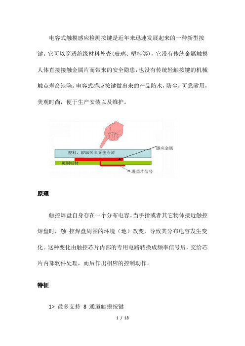
电容式触摸感应检测按键是近年来迅速发展起来的一种新型按键。
它可以穿透绝缘材料外壳(玻璃、塑料等),它没有传统金属触摸人体直接接触金属片而带来的安全隐患,也没有传统轻触按键的机械触点寿命缺陷。
电容式感应按键做出来的产品防水,防尘,可靠耐用,美观时尚,便于生产安装以及维护。
原理触控焊盘自身存在一个分布电容。
当手指或者其它物体接近触控焊盘时,触控焊盘周围的环境(地)改变,导致其分布电容发生变化。
这种变化由触控芯片内部的专用电路转换成频率信号后,交给芯片内部软件处理,而后作出相应的控制动作。
特征1> 最多支持8 通道触摸按键2> 输出可选择为IIC 或者一对一接口(1 脚选择)3> 一对一接口下灵敏度端口电容细调,外部电阻6 级粗调,IIC 下内部寄存器设置,4> 端口内部集成电阻,可省略串入电阻5> 单多按键模式,长短按时间内部寄存器可设置6> 上电0.5S 快速初始化7> 可过电流注入10V、电子群脉冲4KV、静电15KV(非接触)测试8> 防尘、防水、环境改变自动校准应用:广泛应用于油烟机,热水器,面包机,豆浆机,电磁炉等小家电上。
管脚定义及说明管脚图管脚说明电气特性极限参数供电电压.....................................V SS -0.3V~V SS +6.0V端口输入电压.................................V SS -0.3V~V DD +0.3V存储温度................................................-50˚C~125˚C工作温度.................................................-40˚C~85˚CIOL总电流......................................................80mAIOH总电流......................................................80mA总功耗........................................................500mW 注:这里只强调额定功率,超过极限参数所规定的范围将对芯片造成损害,无法预期芯片在上述标示范围外的工作状态,而且若长期在标示范围外的条件下工作,可能影响芯片的可靠性。
融和微触摸按键芯片推广资料-郭泽潭 V1.1
27
USB兼容识别芯片的作用
RH7901/RH7902是USB充电协议端口控制IC,可自动识 别充电设备类型,并通过对应的USB充电协议与设备握手, 使之获得最大充电电流,在保护充电设备的前提下节省充 电时间。
兼容多种USB充电标准
■ Divider1/Divider2/Divider3充电协议(苹果专用) ■ D+/D–置1.2V模式(三星专用) ■ BC1.2 DCP及CTIS YD/T 1591-2009充电协议
44
THE END
谢 谢
45
单键模式:当有数个按键均按住时,只会承认最先被按下的键
6
触摸按键IC名称
按键数
RH6030
1键 直接输出 10uA 1.5uA 2.0~5.5V <7mm
RH6015
1键 直接输出 15uA 5uA
RH6041
4键 直接输出 10uA 1.5uA
RH6010
8键 I2C/脉冲输出 60uA 10uA 2.0~5.5V
CB=0,配置为12W CB=1/悬空,配置为10W 负电源 正电源 连接USB端口DP 连接USB端口DP
GND VDD DP DM
封装:SOT23-5
30
RH7902/A-两通道USB兼容识别芯片 引脚示意图 引脚名称 DP1 GND DP2 DM2 VDD DM1 描述 连接至第一组USB端口DP 负电源 连接至第二组USB端口DP 连接至第二组USB端口DM 正电源 连接至第一组USB端口DM
37
快速充电接口控制器
RH7911是一款快速充电协议的充电接口控制器IC,可自动识别充电设备类型, 并通过充电协议与设备握手,使之获得设备允许的安全最高充电电压,在保护 充电设备的前提下节省充电时间。 ■ ■ ■ ■ ■ ■ ■ ■ ■ ■ ■ A类:5V、9V及12V输出电压 B类:5V、9V、12V及20V输出电压 可选12V或20V输出限制 兼容USB充电规范1.2 默认5V模式工作 待机功耗低 5V输出电压时低于350uW 引脚间短路保护 引脚开路保护及电路故障保护 封装形式:SOP8/SOT23-6 竞品:CHY100
电容式触摸屏基础知识的介绍与学习
15
;小弧度盖板我司定义在1.2mm以下;2.5mm以上定义大弧度。3D盖板暂无资源配合
5.1.4、玻璃常用厚度:0.55、0.7、0.95、1.1、1.5、1.8、2.0、3.0、4.0、 5.0、6.0mm 5.2、P盖板的介绍 5.2.1 盖板用到材料:PC、PET、PMMA、复合板;主要使用PC、PET。复合板主要用于做后盖。做 面板成本太高。 5.2.2 常用厚度: PC、PMMA:0.25-0.38-0.5-0.65-0.8-1.0-1.2-1.5-2.0mm PET:0.188、0.25、0.3mm
2.PI:常见的厚度有1mil与 1/2mil两种.
3.胶:常见厚度为13UM
单面基材 双面基材
26
一、电容式触摸屏的介绍
八、FPC的介绍
8.2 FPC的基本结构与材料(覆盖膜)
1.PI:表面绝缘用.常见的厚度
有1mil与1/2mil. 2.胶:依基材规格和客戶要求
覆盖膜
而決定.常见厚度有15
UM/20UM/25UM
28
一、电容式触摸屏的介绍
工艺流程(普通双面板)
开料
钻孔
沉铜
镀铜
前处理
蚀刻
退膜
固化绿 油
表面处理 (沉镀金)
29 包装
线检 (PQC)
微蚀钝 化
显影
丝印字 符
外观全检 (FQC)
显影
叠覆盖 膜
曝光
固化
冲边框
曝光
层压覆 盖膜
预烤
测试
冲外型
贴干膜
靶冲
丝印绿 油
贴补强
层压补 强
二、不同结构触摸屏的优缺点对比
一、 电容式触摸屏的介绍
Crestron快思聪触摸屏价格哪家便宜,上海凌波代理

Crestron快思聪触摸屏价格哪家便宜,上海凌波代理美国CRESTRON智能控制常用触摸屏(2013-09-10 16:50:27)转载▼快思聪TPMC-3X手持触摸屏ISYS2.8“手持无线触摸屏2.8“的视频触摸屏,增强了Wi-Fi无线性能,令人难以置信的电池寿命,即时唤醒行为。
圆滑和符合人体工程学的手持式设计优雅光泽的黑色漆面倾斜传感器的即时唤醒?行为高性能的802.11a/b/g Wi-Fi无线通信50英尺全方位射频范围室内无线网络摄像机和视频服务器内置扬声器和麦克风快思聪?无线IP对讲功能WAV文件定制的音频反馈广泛分布的触觉按钮白色EL背光按钮上的文字2.8英寸有源矩阵彩色触摸屏高显示亮度和对比度宽150度的可视角度16位彩色图形240×320分辨率动态图形和文字能力长效锂聚合物充电电池时尚的桌面基座壁挂式基座也可(单独出售)尺寸高度 1.04英寸(27毫米),6.34英寸(161毫米)底座宽度 2.55英寸(65毫米),4.58英寸(117毫米)底座深度 7.94英寸(202毫米),6.30英寸(160毫米)底座重量6.6盎司(185克)含电池TPMC-4SM双色背光按键TPMC-4SM标配有10个可编程的“硬键”按钮,用于快速访问常用功能。
每个按钮都设有一个半透明的按钮帽选择红色或绿色LED背光。
背光是完全可调,全球或单独的左侧和右侧。
另外,每个按钮上的LED可以编程,以提供离散反馈,个别按钮的状态,得到明确的指示。
接近传感器TPMC-4SM的感觉,当你接近它,醒来的情况下自动显示触摸屏,所以它总是准备使用。
占位传感快思聪GLS系列传感器可以直接连接TPMC-4SM让房间的照明,气温控制,和其他设备的自动化。
以太网供电POE(以太网供电)消除了一个本地电源或任何专用电源布线的需要。
PoE转换器(PWE 4803RU [单独出售] )简单连接内嵌LAN电缆,可安装在任何方便的位置。
FTC332C-V0

悬空灵敏度高,接地灵敏度低 电源正端 系统中使用1628等芯片驱动数码管时建议一定要给 触摸芯片电源加RC滤波! 接基准电容Cs负端,Cs电容正端接VDD Cs电容须使用5%精度涤纶插件电容、10%高精度的 NPO材质或X7R材质贴片电容 K2触摸盘电容信号输入口 一般使用时串联470欧姆-1K电阻,能有效防止RF干 扰和提升抗ESD静电能力 K1触摸盘电容信号输入口 一般使用时串联470欧姆-1K电阻,能有效防止RF干 扰和提升抗ESD静电能力
2.使用单片PCB,一般用感应弹簧片来做触摸PAD。因为其侧面也能同手指头形成电场,使用感 应弹簧片比使用PCB上做触摸感应PAD能获得更高的灵敏度。
3.触摸感应PAD与地的寄生电容越大,则需要越大的Cs电容来匹配,从而影响Cs电容的取值范 围以及灵敏度的调节范围。所以双面板触摸感应PAD的周围与背面一般建议不铺地,触摸感 应PAD与PAD之间距离足够保持2mm以上,尽量避免不同PAD之平行引线距离过近,这些都能降 低触摸感应PAD对地的寄生电容,有利于产品灵敏度的提高。
Linkman:Yu'R TEL:18680686301 QQ:84211375 Email:hgyufang@
FEIYI Touch key Controller
FTC332C
v0.1
FTC332C触控按键芯片
概述:
触摸感应检测按键是近年来迅速发展起来一种新型按键。它可以穿透绝缘材料外壳(玻 璃、塑料等等),通过检测人体手指带来的电荷移动,而判断出人体手指触摸动作,从而实现 按键操作。电容式触摸按键不需要传统按键的机械触点,也不再使用传统金属触摸的人体直 接接触金属片而带来的安全隐患以及应用局限。电容式感应按键做出来的产品可靠耐用,美 观时尚,材料用料少,便于生产安装以及维护,取代传统机械按钮键以及金属触摸。
KX222 8通道触摸传感开关
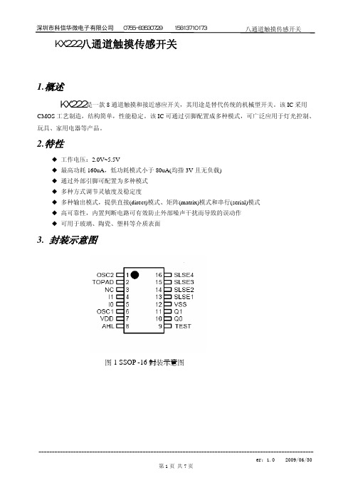
30
Q1
31
Q2
TOUCH 输入端口
32
Q3
33
Q4
34
Q5
35 Q6/RST
36
Q7/CK
灵敏度粗调配置
37
OTC
TOUCH 最大开启时间 Max On Time
系统主时钟 Main CLK
输出模式配置 Output Mode 输出电平配置 Output Low/High
测试端口
TOUCH 输出端口
第3页 共7页
深圳市科信华微电子有限公司 0755-83530729 15813710173 图 2 串行模式
八通道触摸传感开关
5.1.2 输出电平配置
表 5 输出电平配置表
NAME
选项
功能
备注
OLH
=1
输出低电平有效
同时控制 Qx 及 INF
=0
输出高电平有效
5.1.3 TOUCH 最大开启时间配置
图 2 SSOP -28 封装示意图
表 1 引脚描述表
NO. PADNAME
20
MOT0
21
MOT1
灵敏度细调配置
22
MCK
23
GND
Sensitivity Fine Tune
24
VDD
25
OMD1
TOUCH 时钟 TOUCH CLK
26
OMD0
27
OLH
外接 Cj 端口
28
TEST
29 Q0/DAT
传感器有效频率配置 TOUCH CLK
------------------------------------------------------------------------------------------------------er:1.0 2009/06/30
F788-RK3126整机规格书
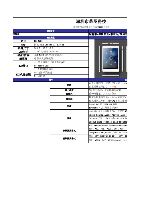
视频播放格式
AVI, MKV(XVID/px/H.264), MOV, TS, M2TS, RM/RM 3GP, MPEG, DAT, MP4(support to 1080P:1920x108
备注
尔达/深玛外壳
图片
MID参数 E 802.11b/g/N无线网络 选) 车游戏 素 0mAH(单节3.7V) I正常工作时间__小时 60Hz 50) , 支持FLASH11.1 layer /Apk /Calculator lorer /ES Task Manager/Global Time Talk/iReader/NC Manager/Google Search wser/Weather Forecast/QQ/Email/Gmail OGG、WAV 20Hz to 20000Hz 64), MOV, TS, M2TS, RM/RMVB, FLV, support to 1080P:1920x1080)
摄像头
前30万像素,后200万像素
锂电池
锂聚合物ห้องสมุดไป่ตู้池容量:3400mAH(单节3.7V) 待机时间__小时,开WIFI正常工作时间__小时
input:AC100-240V 50-60Hz 电源
output:5V 2A(谐波小于50)
android 4.4.4操作系统, 支持FLASH11.1
Video Player/Audio Player /Apk /Calculator
4GB/512M (内存/容量可选)
电容式灵敏触摸屏
1* TF卡槽接口(最大到32GB)
1* Micro USB
1* 3.5MM耳机插孔
1* 电源开关按键
2* 返回键
图片
CPT112S芯科电容触摸按键芯片资料
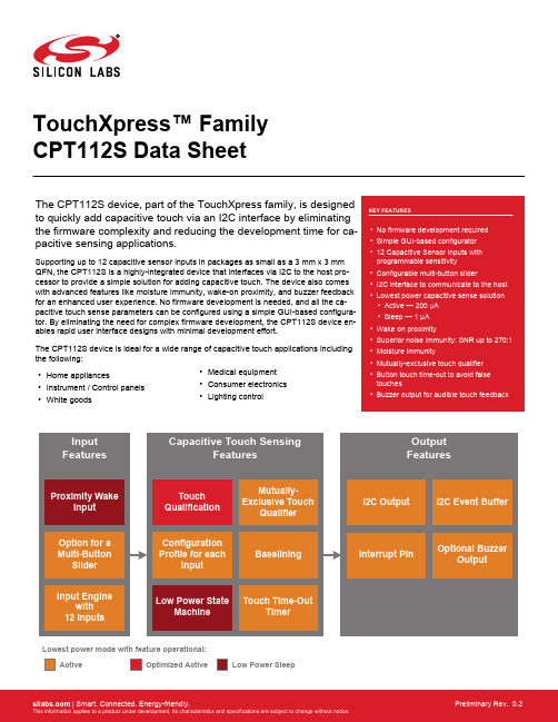
TouchXpress™ Family CPT112S Data SheetThe CPT112S device, part of the TouchXpress family, is designed to quickly add capacitive touch via an I2C interface by eliminating the firmware complexity and reducing the development time for ca-pacitive sensing applications.Supporting up to 12 capacitive sensor inputs in packages as small as a 3 mm x 3 mm QFN, the CPT112S is a highly-integrated device that interfaces via I2C to the host pro-cessor to provide a simple solution for adding capacitive touch. The device also comes with advanced features like moisture immunity, wake-on proximity, and buzzer feedback for an enhanced user experience. No firmware development is needed, and all the ca-pacitive touch sense parameters can be configured using a simple GUI-based configura-tor. By eliminating the need for complex firmware development, the CPT112S device en-ables rapid user interface designs with minimal development effort.The CPT112S device is ideal for a wide range of capacitive touch applications including the following:•Home appliances•Instrument / Control panels •White goods•Medical equipment •Consumer electronics •Lighting controlOptimized ActiveLowest power mode with feature operational:ActiveLow Power SleepFeature List and Ordering Information 1. Feature List and Ordering InformationFigure 1.1. CPT112S Part NumberingThe CPT112S has the following features:•Capacitive sensing input engine with 12 inputs•Post-sample touch qualification engine•Configuration profile space in non-volatile memory•I2C event buffer with interrupt pin to signal when new touch events have been qualified•Low power state machine to minimize current draw in all use cases•Capacitive proximity sensing input•Buzzer output•Mutually-exclusive touch qualifier•Touch time-out timerTable 1.1. Product Selection Guide2. Typical Connection Diagrams2.1 Signal, Analog, and Power connectionsFigure 2.1 Connection Diagram on page 2 shows a typical connection diagram for the power pins of CPT112S devices.Figure 2.1. Connection Diagram2.2 ConfigurationThe diagram below shows a typical connection diagram for the configuration connections pins. The ToolStick Base Adapter is available on the evaluation board.Figure 2.2. Configuration Connection Diagram3. Electrical Specifications3.1 Electrical CharacteristicsAll electrical parameters in all tables are specified under the conditions listed in Table 3.1 Recommended Operating Conditions on page 4, unless stated otherwise.3.1.1 Recommended Operating ConditionsTable 3.1. Recommended Operating Conditions3.1.2 Power ConsumptionSee 3.4 Typical Performance Curves for power consumption plots.Table 3.2. Power Consumption3.1.3 Reset and Supply MonitorTable 3.3. Reset and Supply Monitor3.1.4 Configuration MemoryTable 3.4. Configuration Memory3.1.5 Capacitive SenseTable 3.5. Capacitive Sense3.1.6 Buzzer OutputTable 3.6. Buzzer Output3.2 Thermal ConditionsTable 3.7. Thermal Conditions3.3 Absolute Maximum RatingsStresses above those listed in Table 3.8 Absolute Maximum Ratings on page 9 may cause permanent damage to the device. This is a stress rating only and functional operation of the devices at those or any other conditions above those indicated in the operation list-ings of this specification is not implied. Exposure to maximum rating conditions for extended periods may affect device reliability. For more information on the available quality and reliability data, see the Quality and Reliability Monitor Report at / support/quality/pages/default.aspx.Table 3.8. Absolute Maximum Ratings3.4 Typical Performance CurvesFigure 3.1. Active Mode Processing Time Per SensorNote: Active mode processing time per sensor measured with sensors configured to 1x accumulation, 8x gain. Sensor sampling and system processing time is included with mutually-exclusive buttons, the buzzer, slider, and touch time-outs disabled.Figure 3.2. Current vs. Active Mode Scan Period — Base Current ConsumptionFigure 3.3. Current vs. Active Mode Scan Period — Current Consumption for Each Additional SensorNote: Active mode scan period current draw measured with free run mode disabled and all 12 sensors enabled at 4x accumulation, 8x gain. In addition, the buzzer, slider, and mutually-exclusive button groups were disabled.Figure 3.4. Typical V OH CurvesFigure 3.5. Typical V OL Curves4. Functional Description4.1 Capacitive Sensing Input 4.1.1 IntroductionThe capacitive to digital converter uses an iterative, charge-timing self-capacitance technique to measure capacitance on an input pin.Sampling is configured and controlled by settings in the non-volatile configuration profile, which can be changed through the 2-pin con-figuration interface.C a p a c i t a n c eTimeFigure 4.1. Capacitive Sense Data Types4.1.2 Touch Qualification CriteriaThe device detects a touch event when an inactive (untouched) input enabled by the input enable mask detects an sequence of meas-urements that cross the active threshold.The device detects a touch release event when an active (touched) input enabled by the input enable mask detects an sequence of measurements that cross the inactive threshold.The debounce configuration profile parameter defines how many measurements in a row must cross a threshold before a touch or re-lease is qualified. In electrically noisy environments more heavily filtered data is used for qualification.4.1.3 ThresholdsCapacitive sensing inputs use input-specific thresholds for touch qualification. Each input uses two thresholds, one to detect inactive-to-active transitions on the input, and another to determine active-to-inactive transitions on the input. The inputs use two thresholds to add hysteresis and prevent active/inactive ringing on inputs. Each threshold can be set through Simplicity Studio tools and all thresholds are stored in non-volatile memory in the device's configuration profile.Thresholds are defined as percentages of a capacitive sensing input's touch delta.4.1.4 Debounce CounterEach capacitive sensing input maintains its own debounce counter. For an inactive sensor, this counter tracks the number of succes-sive samples which have crossed that input's active threshold. For an active sensor, this counter tracks the number of successive sam-ples which have crossed the inactive threshold. When the counter reaches a terminal value defined in the the configuration profile, the touch/release event is qualified.4.1.5 Touch DeltasEach capacitive sensing input uses a stored touch delta value that describes the expected difference between inactive and active ca-pacitive sensing output codes. This value is stored in the configuration profile for the system and is used by the touch qualification en-gine, which defines inactive and active thresholds relative to the touch delta.The touch deltas are stored in the configuration profile in a touch delta/16 format. For this reason, touch deltas must be configured as multiples of 16.4.1.6 Auto-Accumulation and AveragingCapacitive sensing inputs have an auto-accumulate and average post-sample filter that can be used to improve signal strength if nee-ded. Settings stored in the configuration profile can configure the engine to accumulate 1, 4, 8, 16, 32, or 64 samples. After the defined number of samples have been accumulated, the result is divided by either 1, 4, 8, 16, 32, or 64, depending on the accumulation setting. This auto-accumulated and averaged value is the sample output used for all touch qualification processing. Note that sample time per sensor increases as the level of accumulation increases. To reduce current consumption, the engine should not be set to auto-accumu-late unless it is required to achieve acceptable signal strength due to thick overlays or other system-level factors.4.1.7 Drive strengthThe drive strength of the current source used to charge the electrode being measured by the capacitive sensing input can be adjusted in integer increments from 1x to 8x (8x is the default). High drive strength gives the best sensitivity and resolution for small capacitors, such as those typically implemented as touch-sensitive PCB features. To measure larger capacitance values, the drive strength should be lowered accordingly. The highest drive strength setting that yields capacitive sensing output which does not saturate the sensing engine when the electrode is active (touched) should always be used to maximize input sensitivity.4.1.8 Active Mode Scan EnableActive mode scanning of capacitive sensing inputs is controlled by an enable setting for each capacitive sensing input. This setting is stored in the configuration profile.4.1.9 Active Mode Scan PeriodThe capacitive sensing input engine stays in active mode whenever one or more inputs have qualified as active. During this time, the sensors scan at a periodicity defined by the active mode scan period, which is stored in the configuration profile. Every active mode scan pushes new samples through the processing engine, which checks for new touch and release events on all enabled inputs.If free run mode is enabled, the engine will repeatedly scan all enabled inputs during the active mode scan period. In this mode of operation, the active mode scan period is used as a timer to determine how much time has passed since the last qualified active sensor has been seen. When a defined amount of time without a qualified touch event has occurred, the engine switches to a low power mode using the sleep mode scan period, and conserves current.If free run mode is disabled, the engine will enter a low power state after completing one scan of all enabled inputs and processing the resulting samples. The engine will remain in this low power state until it wakes, at a time defined by active mode scan period, to perform another scan.4.1.10 Active Mode Scan TypeThe active mode scan type, which is stored in the configuration profile, controls whether the capacitive sensing engine in active mode will scan only once during the active mode scan period before going to sleep, or whether the engine will continue scanning as quickly as possible during the active mode scan period, never entering a low power state.For optimal responsiveness, the engine should be configured to run with free run mode enabled. Setting the scan mode to 'free run' causes touch qualification on a new touch to occur as quickly as the scanning engine can convert and process samples on all sensors. In this mode, qualification time is not bounded by active mode scan period, and is only bounded by scanning configuration factors such as the debounce setting, the number of enabled sensors, the accumulation setting on each sensor, and the timing constraints of any enabled component.For optimal current draw when in active mode, the engine should be configured to use the 'one scan per period' mode setting. In this case, touch qualification is bound by the scan period and the debounce setting of the device.Touch Event(t = 0 ms)10 ms20 ms30 ms40 msFigure 4.2. Timing and Current — One Sample Per Period ModeTouch Event10 ms20 ms30 ms40 ms(t = 0 ms)4.1.11 Sleep Mode Scan PeriodThe sleep mode scan period defines the rate at which a scan of the inputs enabled as wake-up sources are sampled. Each enabled sensor can also be enabled as a wake-up source. After the sleep mode scan completes, the scan is processed for a qualified candidate touch. If a candidate touch is qualified, the system wakes form sleep mode and enters active mode scanning.The sleep mode scan period is stored in the configuration profile and is defined in units of ms.4.1.12 Active Mode and Sleep Mode TransitionsCapacitive sensing inputs will stay in active mode until no inputs detect qualified touches for a span of time defined by the counts until sleep parameter stored in the configuration profile. The scan period of enabled inputs is defined by the active mode scan period, also found in the configuration profile. If free run mode is enabled, the active mode sensing engine will remain awake and scanning the sen-sors as fast as possible. If free run mode is disabled, the engine will put itself into a low power state for the remainder of the active mode scan period, after a scan has completed.When in sleep mode, the sensing engine will wake at a period defined by sleep mode scan period to do a scan on sensors that have been enabled as wakeup sources. If the engine finds a candidate touch in this state, the system reverts to active mode to continue scanning.Note that in systems where a proximity input is selected, the sleep mode scan engine uses conversions on the proximity input instead of sensors enabled as wakeup sources.Devices configured to wake on a touch will attempt to qualify the candidate touch that initiated the sleep-to-active transition. If qualifica-tion completes successfully, the device will signal this qualification to the external system. Touch qualification of this candidate touch uses the same active mode thresholds, debounce setting, and active mode scan period settings as any touch that occurs during active mode scanning.D e v i c eE x e c u t i o nFigure 4.4. Active and Sleep Transitions4.2 I2C Event Buffer Interface4.2.1 IntroductionThe event buffer I2C interface provides an event-driven, packetized communication system describing newly qualified events generated by the capacitive sensing input engine.The interface provides access to a first-in-first-out buffer of data packets. When the sensing engine generates these packets and push-es them onto the buffer. The interface then signals a host to indicate that one or more packets are available in the buffer by activating the event buffer interrupt pin.The interrupt pin is defined as active-low and operates as a push-pull digital output.The host reads the packets through an I2C interface, with the host acting as an I2C master. Once all packets have been fully transmit-ted across the I2C interface, the event buffer interrupt pin is de-activated. The device will remain in active mode until no packets remain in the buffer, even if no sensors have been qualified as active for the period of time defined by the active mode scan period and the counts before sleep value.4.2.2 Packet retrieval in operational modeWhen the least significant byte of the CRC of an event packet has been transferred during a master read transaction, that event is popped from the device's buffer. If only a part of the event is read, the event will stay in the buffer and will be transmitted again by the device during the next read.If the host initiates a master read when the device is in operational mode but the interrupt pin is not active, signifying that the device has no events in its buffer to transmit, the device will NACK its slave address on the bus.If the I2C master sends a stop condition on the bus before the entire three-byte packet has been read, the device will not pop the pack-et from its internal buffer. Instead, the I2C state machine will reset, and the next transaction will begin with the first byte of the same event that was being read in the previous, prematurely-terminated transaction.The I2C event buffer has a depth of 22 events. If the host does not read events promptly after seeing the interrupt pin go active, there is the possibility of a buffer overflow. In the event of an overflow, the I2C engine will discard the oldest events first.New I2C packets will only be generated at the active mode sample rate, and so the buffer will only fill at a maximum of 12 packets (in the case of 12 simultaneous touch/releases) per sample period. If the host runs the I2C bus at 400kHz and reads packets as soon as the interrupt pin activates, all packets can be read from the buffer in 1 to 2 ms, which is faster than the rate at which a new active mode scan sequence can complete.4.2.3 Event Packet StructureEvery qualified event detected by the capacitive sensing input engine generates a single packet that can be retrieved by the host pro-cessor through the event buffer I2C interface. The packet is an atomic data unit that fully describes the generated event.Note: The bytes in the packet are transmitted MSB first.Each packet has a standard structure that can be parsed by the host.Table 4.1. Standard Packet StructureThe packet counter is a 4-bit number stored in the upper bits of byte 1. Each new event will be assigned a counter value that is +1 from the last qualified event. After event 15, the counter wraps back to 0 for the next event. The counter captures the temporal nature of touch events so that a host can reconstruct a sequence of events over time. Also, the host can use the counter value to determine if a packet has been lost due to a buffer overflow.The event type is a 4-bit value describes the originator of the event. For instance, the source could be a capacitive sensing button. The event type is stored in the lower 4 bits of byte 1.The event description bytes define characteristics of the event that have been qualified. Event descriptions are defined relative to the event source. An event source that is a capacitive sensing input will have a defined set of valid event description values. Those same values will mean something different for a different type of event source, such as a slider. Event description values are defined relative to the event type field of byte 1.Touch Event I2C Slave Address+ read bitCSxx index reserved byte 0byte 1byte 2byte 3Touch Release Event I2C Slave Address+ read bitCSxx index reserved byte 0byte 1byte 2byte 3Slider Event I2C Slave Address+ read bitslider position(MSB)slider position(LSB) byte 0byte 1byte 2byte 3packetcounter0010eventtype0000packetcounter0011eventtype0001packetcounter0100eventtype0010Figure 4.5. I2C Event Buffer Packet Structure4.2.4 Defined Event TypesThe device assigns the following event types to events.Table 4.2. Event Type MappingNote that this event type value is stored in the lower 4 bits of the first byte of a packet. The upper 4 bits are a packet counter value.4.2.5 Description Bytes for Touch EventsA touch or release event uses only one byte of the description field. That field identifies which sensor caused the touch or release event as shown below.Table 4.3. Touch or Release Event Sensor Mapping4.2.6 Description Bytes for Slider EventsThe slider activity description field uses two bytes to describe the position of the slider, which can be any value between 0 (0x0000) and 65534 (0xFFFE). The most-significant byte of this value is transmitted in the first byte (byte 2 of the event packet), and the least-signifi-cant byte is transmitted second (byte 3 of the event packet).When the slider is released, a final slider event will be transmitted with 0xFFFF in the two-byte field.4.2.7 Event Buffer I2C Slave AddressThe device's I2C slave address is configurable through the configuration profile. The device will ACK its slave address only when the interrupt pin is low, signalling that a packet is ready to be read by the host. If the interrupt pin is logic high, the device will not ACK its slave address.4.3 Capacitive Proximity Sensing4.3.1 Wake on ProximityThe wake on capacitive proximity detection engine monitors for the presence of a conductive object such as a hand to move within detectable range of the sensor. When the engine detects an object, the device wakes from sleep and can begin qualifying touch events on all sensors enabled for active mode sensing.4.3.2 Proximity ConfigurationThe proximity sensing feature uses a single sensor input for proximity qualification. The configuration profile stores the pin chosen by the user. The sensor used for proximity qualification should also have a drive strength setting that is as high as possible without saturat-ing the input when no conductive object is in proximity to the proximity sensor. The accumulation setting of the input is also configura-ble.The proximity threshold controls the sensitivity of the input. A lower threshold setting increases sensitivity and increases the range of the sensor.A proximity sensing input cannot be used for touch qualification, and so the active and inactive thresholds are not used for proximity sensors. Additionally, the proximity input has no effect on other components of the device such as mutually exclusive button groups, buzzer output, touch time out timers, and sliders.4.4 SliderThe device supports creation of a single slider that is composed of two or more capacitive sensing input pins. The pins chosen as slider inputs are assigned to the slider feature through the configuration profile.The configuration profile also stores a value designated as the highest positional value that can be derived by the slider engine. That highest value is used to derive the values of all intermediate positions on the slider array.When a capacitive sensing input pin is designated as a slider input, it will no longer function as a 'button' input and will not generate button style touch/release events across the I2C buffer interface.Touching the slider pads and moving a finger along a slider pad generates an event packet of type Slider, with the remaining two bytes of the packet describing the calculated active position of the slider.The range of possible reported slider active positions can be 0 to the maximum value of the slider as defined in the configuration profile,which can be any value between 40 and 65534. The 65535 (0xFFFF) value is reserved for a slider untouched event.Position 0 is always assigned to the lowest CSxx sensor enabled as a slider input. The maximum position value of the slider is assigned to the highest CSxx sensor enabled as a slider input. All slider inputs in between are assumed to be routed to the slider contiguously,lowest to highest.InvalidConfigurationValidConfigurationincreasing slider positionValidConfigurationpositionFigure 4.6. Slider Behavior and Layout ConstraintsSlider touch qualification uses the same touch deltas and thresholds that are defined in the configuration profile for all enabled sensors.The user should configure slider sensors through the configuration profile, just as one would configure a sensor assigned to a capaci-tive button.For optimal performance, each sensor used in the slider should have roughly the same touch surface area dimensions.If the touch-timeout feature is enabled, slider-assigned inputs will also be subject to being qualified as releases by the touch-timeout feature.The mutually exclusive button grouping feature does not affect slider-assigned sensors. Even if the mutually exclusive button grouping feature is enabled, multiple slider-assigned sensors can still be used to resolve a finger's position on the slider.4.5 Touch Time-OutThe touch time-out feature can be enabled and disabled through the configuration profile. When enabled, the device will monitor touch event duration on each input independently.When a touch event exceeds a duration specified in the configuration profile, the device forces a release event, even if the user is still actively touching the sensor.The feature qualifies a touch release by adding the configured touch delta value for that sensor to the sensor's current baseline value. By doing this, the raw data-to-baseline delta created by the touch will be removed, and the touch qualification engine will see this as a touch release event.When the user removes a finger from a sensor that had been qualified active but has been qualified released through touch timeout, the resulting raw-to-baseline negative delta will be aggressively tracked downward by the baseline, resulting in a sensor that remains sensi-tive to successive touches.The touch timeout duration is configured globally, so all inputs are monitored for the same touch duration.If both the touch timeout feature and the mutually exclusive button group feature are enabled, the timeout timer will only run on the touch that is externally reported as being active.4.6 Buzzer Output4.6.1 IntroductionThe buzzer output engine produces a square wave of a configurable duration and frequency when a capacitive sensing input goes from inactive to active. The feature can be enabled and disabled through the configuration profile. The configuration profile also includes the settings for active duration and frequency.Device ExecutionActiveOptimizedActiveSleepNo Touch, Buzzer InactiveFigure 4.7. Effects of the Buzzer on Current Draw — Active Mode, No Touch, Buzzer InactiveDevice ExecutionActiveOptimizedActiveSleepTouch Detected, Buzzer ActiveFigure 4.8. Effects of the Buzzer on Current Draw — Active Mode, Touch Detected, Buzzer Active4.6.2 Buzzer ConfigurationWhen enabled, buzzer output will appear on the CS11/buzzer pin (pin 10) of the device. When buzzer output is enabled, CS11 is not available for capactive input sensing.When activated, the buzzer will remain active for either the duration specified in the configuration profile, or until the last active sensor has qualified a touch release.The configuration profile supports configuration of output frequencies ranging from 1 kHz to 4 kHz.The configuration profile can configure the buzzer output pin to either push pull mode or open drain mode.4.7 Mutually Exclusive ButtonsWhen enabled through the configuration profile, this system allows one and only one capacitive sensing input to be qualified as active at a time. The first sensor active will remain the only sensor active until released. The device will internally qualify multiple touch and release events but will not report them.If multiple sensors have been internally qualified as active, the first sensor's touch event will be reported. If a touch event occurs simul-taneously on more than one sensor, the touch with the highest touch delta will be reported.If two sensors are qualified as active and the sensor being reported as active qualifies a touch release, the device will report that re-lease and then report a touch qualification on the still-active second sensor.In the case where a device has simultaneously qualified more than two active sensors and the reported active sensor qualifies and reports a release, the remaining qualified sensor with the highest sensor name will then be reported. For example, if sensors CS00,CS01, and CS02 are active with CS00 externally reported as active, after CS00's release, CS02 would be externally reported as an active sensor unless the device has already qualified a touch release on CS02.If both the touch timeout feature and the mutually exclusive button group feature are enabled, the timeout timer will only run on the touch that is externally reported as being active.Device Executionphysical touch on pad touch reported by CPT device release reported by CPT deviceFigure 4.9. Mutually-Exclusive Button Operation4.8 Self Testing4.8.1 IntroductionWhen the self-test feature is enabled through the configuration profile, the device performs a check on all enabled capacitive sensing inputs upon startup to determine whether the sensing input pins are erroneously shorted to ground or supply. If a short or open is found on a sensor, the self test feature will signal that an error has been found through a port pin. The feature will then disable that sensor before beginning touch qualification scans on all sensors left enabled.4.8.2 Test Failure SignalingIf the self test check reveals an error, the device will toggle the I2C buffer interrupt pin at a frequency of 2 Hz. This toggling will persist for two seconds if the device detects one or more self test errors.4.9 Configuration ProfileThe configuration interface is used by the device to configure default values and performance characteristics that effect capacitive sensing. The configuration data can be programmed through the Configuration interface (Config Clk and Config Data pins) using [Con-figurator] in Simplicity Studio.Several configuration profile templates are available in Simplicity Studio to provide a starting point for development.。
ESP32-PICO-V3-02 技术规格书说明书

ESP32PICOV302技术规格书版本1.0乐鑫信息科技版权©2021关于本文档本文档为用户提供ESP32-PICO-V3-02的技术规格信息。
文档版本请至乐鑫官网https:///zh-hans/support/download/documents下载最新版本文档。
修订历史请至文档最后页查看修订历史。
文档变更通知用户可以通过乐鑫官网订阅页面/zh-hans/subscribe订阅技术文档变更的电子邮件通知。
您需要更新订阅以接收有关新产品的文档通知。
证书下载用户可以通过乐鑫官网证书下载页面/zh-hans/certificates下载产品证书。
1产品概述1.1特性MCU•内置ESP32芯片,Xtensa®双核32位LX6微处理器,支持高达240MHz的时钟频率•448KB ROM•520KB SRAM•16KB RTC SRAMWiFi•802.11b/g/n•802.11n数据速率高达150Mbps•支持A-MPDU和A-MSDU聚合•支持0.4µs保护间隔•工作信道中心频率范围:2412~2484MHz蓝牙®•蓝牙V4.2BR/EDR和蓝牙LE标准•Class-1、class-2和class-3发射器•AFH•CVSD和SBC硬件•SiP接口:ADC、DAC、触摸传感器、SD/SDIO/MMC主机控制器、SPI、SDIO/SPI从机控制器、EMAC、电机PWM、LED PWM、UART、I2C、I2S、红外遥控、GPIO、脉冲计数器、TWAI®(兼容ISO11898-1,即CAN规范2.0)•40MHz晶振•8MB SPI flash•2MB SPI PSRAM•工作电压/供电电压:3.0~3.6V•建议工作温度范围:–40~85°C•封装尺寸:(7×7×1.11)mm1.2描述ESP32-PICO-V3-02是一款基于ESP32(ECO V3)的系统级封装(SiP)产品,可提供完整的Wi-Fi和蓝牙®功能,集成1个8MB串行外围设备接口(SPI)flash和1个2MB串行外设接口PSRAM。
电容触摸传感简介 Microchip AN1101 说明书

12
3
4
上电
AN1101
SQ RQ
C2OUT
时间
表 2:
工作时间段
时间段
置位
复位
1 2 2⇒3 3 3⇒4 4=2
C1+ > VS=0
C2+ > VR=1
C1+ > VS=0
C2+ < VR=0
C1+ < VS=1
C2+ < VR=0
C1+ > VS=0
C2+ < VR=0
C1+ > VS=0
C2+ < VR=1
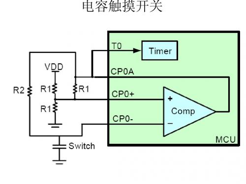
一种观测频率是否下降的简单方法是使用三个无符号整 型变量,它们是:
unsigned int average; unsigned int raw; unsigned int trip;
变量 average 存放前面 16 个采样值的滑动平均值; raw 是从 Timer1 读取的当前传感器数据;而 trip 则是按钮按 下时频率与平均值的差。最简单的检测按钮是否按下的 算法就是测试 raw 是否比平均值还要小某个固定值,其 代码示例如下。
注:
检测按钮是否按下的更好的软件算法,在 AN1103《电容触摸传感的软件处理》中进 行了讨论。上面的例子非常简化地说明了 频率下降是检测按钮是否按下的常用基本 的方法。
AN1101
配置 PIC® MCU
目前有三个系列的 PIC 单片机能实现前面介绍的方法, 它们是 Microchip PIC16F616 系列、PIC16F690 系列以 及 PIC16F887 系列。用于电容触摸传感的基本寄存器 设定是一样的,尽管系列之间的差异可能导致寄存器设 定值上有小小的不同。附录 A: “PIC16F887 系列的寄 存器设置 ” 详细说明了如何正确设置 PIC16F887 系列。 对于其他系列的器件,也可把 附录 A:“PIC16F887 系 列的寄存器设置 ” 用作设置寄存器位的指导。 用于电容触摸传感时需要设置的寄存器如下:
奥普尚科技 ASC8022K ASC8022S 电容式触摸控制 ASIC 芯片说明书
销售部2:TEL:130****8198,QQ:2881651176 投诉与建议:134****1600数据手册DATASHEETASC8022K(同步模式直接输出) ASC8022S(保持模式锁存输出) 2键触摸感应开关芯片IC(Rev:1.4)销售部2:TEL:130****8198,QQ:2881651176投诉与建议:134****1600一、产品概述ASC8022K、ASC8022S是为实现人体触摸界面而设计的一款电容式触摸控制ASIC芯片,可替代机械式轻触按键,实现防水防尘、密封隔离、坚固美观的操作界面。
支持2通道触摸输入和输出,具有低功耗、高抗干扰、宽工作电压范围、高穿透力的突出优势。
二、主要特性1、工作电压范围:2.4~5.5V。
2、待机功耗低, 待机电流:9uA@VDD=5V & CMOD=10nF;6.5uA@VDD=3V & CMOD=10nF。
3、按键响应时间:小于100ms。
4、上电0.5秒快速初始化。
环境自适应功能,可快速应对先上电后覆盖介质、触摸上电等应用场景。
5、HBM ESD:±5KV以上。
6、按键持续长按最长时间:16秒(±30%)7、采用电荷分享方式实现触摸,独立2通道触摸按键输入输出。
8、有效电平选择(AHLB):可引脚配置高电平输出有效或低电平输出有效9、内置高精度LDO稳压源电路单元模块、上电复位(POR)、低压复位(LVR)、硬件去抖。
10、内置实时环境自适应算法,可随环境温度变化、触摸介质的环境变量调整参考值,确保按键判断正常工作。
11、内置高效数字滤波算法措施,抗电源纹波能力强,对电源纹波的干扰有很好的耐受能力,可抵抗<0.5V的电源纹波。
可靠性高,不影响芯片正常工作,有效防止由外部噪声干扰导致的误动作。
12、抗大功率RF发射设备、对讲机干扰能力强,近距离、多角度干扰情况下触摸响应灵敏度及可靠性不受影响。
13、高灵敏度,用户可自行调节, CMOD脚的外接电容Cm为灵敏度调节电容,电容越大灵敏度越高。
HC8T0810 规格说明书V1.1(简易版)

HC8T08108通道可编程电容式触摸芯片规格说明书V1.1目录1. 概述 (3)2. 特性简介 (3)3. 管脚定义及功能描述 (4)4. 封装尺寸图 (5)5. 应用电路图 (7)6. 绝对额定值 (7)7.电气特性参数 (8)7.1直流电气参数 (8)7.2交流电气参数 (9)1. 概述HC8T0810 是一款有8个触摸通道和10个通用I/O端口的8位MCU芯片。
它具有8位MCU核,OTP-ROM (一次可写入只读存储器),SRAM(静态随机存储器),TIMER(定时器),COUNTER(计数器),GPIO(通用输入输出口),并具有中断和唤醒功能。
2. 特性简介微控制器特性简介:• 工作电压范围:2.4V~5.5V• 工作频率:32KHz~16MHz• 触摸通道数量:8• 通用I/O端口数量:10• 8位MCU 内核• 4K×14位OTP-ROM• 144*8位SRAM• 时钟源:2个• 中断源:6个• 8位RTC定时器,具有溢出中断功能• 8位TCC定时器,具有溢出中断功能• WDT或者TCC的8位预分频器• 内置上电复位(POR)• 上电复位定时器(PWRT)和振荡起振定时器(OST)• 带有RC振荡器的看门狗定时器(WDT)• 内置低电压复位(LVR)• 采用低功耗的CMOS工艺技术系统工作模式:HC8T0810 支持4种工作模式:✧正常模式:MCU工作,HRC工作(或HRC与LRC同时工作),此时功耗最高。
✧低速模式::MCU工作,HRC不工作,LRC工作,此时功耗一般。
✧空闲模式::MCU不工作,HRC不工作,LRC工作,此时功耗较低。
✧睡眠模式::MCU、HRC和LRC都不工作,此时功耗最低。
3. 管脚定义及功能描述注:在OTP-ROM编程模式下,部分功能管脚具有如下复用功能(功能管脚名称/复用烧录管脚名称):RST_EXTb/VPP,复用作OTP高压编程电源输入端口P2.1/DOUT,复用作数据串行输出端口P2.0/VPP_ACT,复用作编程使能状态输出端口TS4/OEB,复用作数据输出使能信号输入端口TS3/PGMB,复用作编程使能信号输入端口TS2/DIN,复用作数据串行输入端口TS1/DCLK,复用作编程时钟输入端口TS0/CEB,复用作片选使能信号输入端口4. 封装尺寸图TSSOP24SOP247.电气特性参数7.1直流电气参数(VDD-VSS = 3.0V, 无负载, 主时钟= 4MHz, 子时钟= 32768HZ在晶振模式下. Ta = 25℃)7.2交流电气参数。
2-3 单片机的结构和原理-内部时钟源
void main(void) { unsigned char cnt1=0,cnt2=0; SOPT1 = 0x43; PTBDD = 0xff; for(;;) { if((cnt1++%10) == 0) { cnt2++; ICSC2 = (cnt2%4)*64; } PTBD_PTBD6 = 1; delay(200); PTBD_PTBD6 = 0; delay(200); } }
JM60_MCG
Example # 1: FEI切换到PEE Mode: External Crystal = 4 MHz,Bus Frequency = 8 MHz
1. 首先, FEI 必须切换到FBE模式 a) MCGC2 = 0x36 (%00110110) – BDIV (bits 7 and 6) set to %00, or divide-by-1 – RANGE (bit 5) set to1, 因为4 MHz属于高频范围 – HGO (bit 4) set to 1选择高增益 – EREFS (bit 2) set to 1, 选择晶体振荡器 – ERCLKEN (bit 1) set to1,允许外部时钟 b) 查询直到OSCINIT( MCGSC )为1, 表明外部振荡稳定 c) MCGC1 = 0xB8 (%10111000) – CLKS (bits 7 and 6) set to %10 选择外部时钟作为系统时钟 – RDIV (bits 5-3) set to %111, 4 MHz / 128 = 31.25 kHz – IREFS (bit 2) cleared to 0, 选择外部参考 d) 查询直到IREFST (MCGSC)为 0,表明外部时钟作为参考ok e) 查询直到CLKST(MCGSC)为 %10, 表明外部时钟运行ok
3路电容式触摸芯片 -回复

3路电容式触摸芯片-回复什么是3路电容式触摸芯片?3路电容式触摸芯片是一种集成电路芯片,主要用于触摸应用,可以检测和解析电容变化,从而实现触摸操作。
它通常是由触摸感应电路和处理芯片组成,可以广泛应用于电视、手机、平板电脑、智能家居和工业控制等领域。
第一步:了解电容式触摸技术的原理在深入了解3路电容式触摸芯片之前,我们首先需要了解电容式触摸技术的原理。
简而言之,电容式触摸是利用了人体电导率与物体之间的接触而产生的电容变化。
当人体或物体接近触摸屏时,电场中的电荷分布发生变化,触摸芯片通过感应电路可以检测到这种变化。
第二步:探究3路电容式触摸芯片的工作原理3路电容式触摸芯片将电容式触摸技术应用于实际操作中。
它通过三个独立的电容电路,即三路触摸感应电路,来实现对触摸的检测和解析。
这三个电路可以分别与三个触摸区域相连,也可以与同一触摸区域的不同部分相连。
当触摸发生时,触摸区域与感应电路之间的电容会发生变化。
3路电容式触摸芯片会通过感应电路对这种变化进行检测,并将检测到的信号传输给处理芯片进行处理。
第三步:分析3路电容式触摸芯片的应用由于3路电容式触摸芯片具有高灵敏度、低功耗和可靠性等优势,它已经广泛应用于各种设备和系统中。
在手机和平板电脑中,3路电容式触摸芯片可以实现多点触控功能,用户可以通过手指在屏幕上滑动、缩放或旋转进行操作,大大增强了用户体验。
在电视和电视机顶盒中,3路电容式触摸芯片可以用于触摸遥控器,可以替代传统的按钮和按键,增加了操作的便捷性和舒适性。
在智能家居系统中,3路电容式触摸芯片可以用于智能开关、调光器或温控面板等设备,用户可以通过触摸操作控制灯光、窗帘或温度,实现智能化管理。
在工业控制领域,3路电容式触摸芯片可以应用于机器人、自动售货机和机械设备的控制面板等,可以快速准确地响应用户的触摸操作,提高生产效率和操作便捷性。
总结:通过理解3路电容式触摸芯片的工作原理和应用领域,我们可以得出结论,3路电容式触摸芯片是一种先进的技术,它已经成为现代世界中不可或缺的一部分。
三通道电容式触摸键芯片XC2863规格书
三通道电容式触摸键控制芯片XC2863目录1概述 (3)1.1 特性 (3)1.2 系统框图 (4)2管脚定义 (5)3功能描述 (6)4电气特性 (7)5关键特性 (8)5.1 环境自适应能力 (8)5.1.1环境漂移跟随 (8)5.1.2环境突变校准 (8)6应用指南 (9)7PCB设计 (10)7.1 触摸键设计 (10)7.1.1触摸键 (10)7.1.2触摸键的常用结构 (10)7.1.3触摸键设计 (11)7.2 PCB布线 (11)8封装 (12)1概述XC2863是矽励微电子推出的一款支持宽工作电压范围的三输入三输出电容式触摸键控制芯片。
XC2863内部集成高分辨率触摸检测模块和专用信号处理电路,以保证芯片对环境变化具有灵敏的自动识别和跟踪功能,且内置特殊算法以实现防水、抗干扰等需求。
该芯片可满足用户在复杂应用中对稳定性、灵敏度、功耗、响应速度、防水、带水操作、抗震动、抗电磁干扰等方面的高体验要求。
XC2863为方便用户在应用中可对触摸键的灵敏度进行自主控制,特设置了灵敏度控制位。
用户只需在PCB设计中对这个管脚的逻辑电平值进行设置,就能自由选择在具体应用中芯片体现出的检测灵敏度。
XC2863还内置了上电复位及电源保护电路,在典型应用中可无需任何外部器件,也无需软件、程序或参数烧录。
芯片应用的开发过程非常简单,最大限度的降低了方案成本。
XC2863可广泛适用于遥控器、灯具调光、各类开关以及小家电和家用电器控制界面等应用中。
1.1特性工作电压:2.5V~5.5V三个高灵敏度的触摸检测通道无需进行参数烧录响应速度快抗电磁干扰能力强防水及带水操作功能独特的环境跟踪和自适应能力低功耗(典型工作电流< 25uA)内置上电复位(POR)和电源保护电路C MOS电平输出1.2系统框图XC2863包含PMU和Touch Key Core两个部分,其系统框图如图1所示。
图1 XC2863的系统框图2管脚定义XC2863采用SOP8封装,管脚分布如图2所示。
TCH683
Page 2 of 7
深圳市钜盛电子有限公司 TH683
功能脚说明:
y Q0、Q1可作灵敏度选择,作为调Cs电容外的另外一个调节灵敏度的方法。 接地灵敏度低,悬空高。具体排列如下: Q0接地、Q1接地,灵敏度最低。 Q0悬空、Q1接地,灵敏度稍高。 Q0接地、Q1悬空,灵敏度次高。 Q0悬空、Q1悬空,灵敏度最高。
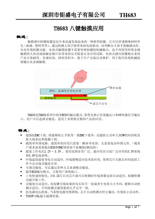
TH683是TH68X系列中的带BCD码输出模式,带背光指示有效输出口和蜂鸣器信号输出 口,用户可以选择灵敏度,适用于各种影音数码产品的应用。
特点:
y 超强抗EMC干扰,除能够防止手机等一般EMC干扰外,还能防止功率大到5W的对讲机发 射天线靠近和接触干扰。
y 极简单外围电路,最简单的应用只需要一颗参考电容,无需要复杂外围元件。(视客 户要求如需要提高ESD和EMC则需每个按键接1颗电阻)
1
0
0
1
K4+K8组合键
1
0
1
0
无按键
1
1
1
1
Page 3 of 7
深圳市钜盛电子有限公司 TH683
注意事项:
1. 使用用双面PCB,可以在顶层使用圆形、方形等作为触摸PAD,从触摸PAD到IC管脚 的连线应该尽量走在触摸点PAD的另外一面。同时连线应该尽量走细,不要绕太远。 使用单面板则一般需要使用感应弹簧片。
y Q2 可以做蜂鸣器信号输出,按键有效时输出4KHz交流信号,可以直接驱动陶瓷压电 蜂鸣器,也可以加三极管驱动线圈蜂鸣器。蜂鸣器每次按键持续时间为60ms。
- 1、下载文档前请自行甄别文档内容的完整性,平台不提供额外的编辑、内容补充、找答案等附加服务。
- 2、"仅部分预览"的文档,不可在线预览部分如存在完整性等问题,可反馈申请退款(可完整预览的文档不适用该条件!)。
- 3、如文档侵犯您的权益,请联系客服反馈,我们会尽快为您处理(人工客服工作时间:9:00-18:30)。
三通道电容式触摸键控制芯片
XC2863
目录
1概述 (3)
1.1 特性 (3)
1.2 系统框图 (4)
2管脚定义 (5)
3功能描述 (6)
4电气特性 (7)
5关键特性 (8)
5.1 环境自适应能力 (8)
5.1.1环境漂移跟随 (8)
5.1.2环境突变校准 (8)
6应用指南 (9)
7PCB设计 (10)
7.1 触摸键设计 (10)
7.1.1触摸键 (10)
7.1.2触摸键的常用结构 (10)
7.1.3触摸键设计 (11)
7.2 PCB布线 (11)
8封装 (12)
1概述
XC2863是矽励微电子推出的一款支持宽工作电压范围的三输入三输出电容式触摸键控制芯片。
XC2863内部集成高分辨率触摸检测模块和专用信号处理电路,以保证芯片对环境变化具有灵敏的自动识别和跟踪功能,且内置特殊算法以实现防水、抗干扰等需求。
该芯片可满足用户在复杂应用中对稳定性、灵敏度、功耗、响应速度、防水、带水操作、抗震动、抗电磁干扰等方面的高体验要求。
XC2863为方便用户在应用中可对触摸键的灵敏度进行自主控制,特设置了灵敏度控制位。
用户只需在PCB设计中对这个管脚的逻辑电平值进行设置,就能自由选择在具体应用中芯片体现出的检测灵敏度。
XC2863还内置了上电复位及电源保护电路,在典型应用中可无需任何外部器件,也无需软件、程序或参数烧录。
芯片应用的开发过程非常简单,最大限度的降低了方案成本。
XC2863可广泛适用于遥控器、灯具调光、各类开关以及小家电和家用电器控制界面等应用中。
1.1特性
工作电压:2.5V~5.5V
三个高灵敏度的触摸检测通道
无需进行参数烧录
响应速度快
抗电磁干扰能力强
防水及带水操作功能
独特的环境跟踪和自适应能力
低功耗(典型工作电流< 25uA)
内置上电复位(POR)和电源保护电路
C MOS电平输出
1.2系统框图
XC2863包含PMU和Touch Key Core两个部分,其系统框图如图1所示。
图1 XC2863的系统框图
2管脚定义
XC2863采用SOP8封装,管脚分布如图2所示。
图2 XC2863管脚分布XC2863的管脚描述如表1所示。
3功能描述
XC2863具有3个触摸检测通道(IN0,IN1和IN2)和3个触摸检测的输出管脚(OUT0,OUT1和OUT2)。
输出管脚OUT0、OUT1和OUT2为CMOS电平输出,输出的逻辑高电平为AVDD。
当触摸检测通道IN0,IN1或IN2上检测到触摸,触摸检测通道对应的输出管脚OUT0,OUT1或OUT2输出逻辑高电平,否则输出逻辑低电平
4电气特性
XC2863的电气特性如表2所示。
5关键特性
5.1环境自适应能力
当外界环境发生突变或缓慢变化时,XC2863都能够监测并自适应这种变化,通过内部算法进行自动调整从而始终保持最佳的灵敏度,使得芯片在复杂多变的应用环境中能够一直准确地进行触摸识别和判断。
XC2863的以下两项技术保证了其对环境的自适应特性。
5.1.1环境漂移跟随
XC2863的环境漂移跟随技术实时监测外部环境的缓慢变化,并自动调整其检测灵敏度以适应该变化,确保触摸体验不受外部环境影响。
5.1.2环境突变校准
XC2863的环境突变校准技术可以应对外部环境的突然变化。
XC2863自动识别外部环境突变所引起的触摸操作,并通过自动校准消除其影响。
6应用指南
触摸键
触摸键的应用中,触摸检测通道IN直接与触摸键的PCB设计相连接。
触摸键的典型应用如图3。
图3 触摸键典型应用
说明:
图中KEY0、KEY1和KEY2为PCB上的触摸键设计,分别与触摸检测通道IN0、IN1和IN2相连。
图中虚线框中的电阻R0、R1、R2和发光二极管LED0、LED1、LED2,仅为示例(如在需要用LED指示相应的OUT输出结果时可以使用)。
在AVDD和地之间接1uF的滤波电容(如图中虚线电容C1所示)。
OUT0、OUT1和OUT2为CMOS电平输出,具备驱动能力,均可与其他芯片连接。
7 PCB设计
7.1触摸键设计
7.1.1触摸键
触摸键一般由感应电极和覆盖在感应电极上的介质构成。
在某些应用中,感应电极上没有覆盖介质,感应电极直接充当触摸键。
触摸键的感应电极上的最顶层的介质层通常称为面板。
触摸键的感应电极通常由电阻率低的导电材料制作,常用的材料包括铜、ITO 等。
几乎所有的绝缘材料都可以用来制造触摸键的介质层。
相同厚度下,介电常数越大,触摸动作所引起的触摸键的电容的变化越明显,即表现为更灵敏。
7.1.2触摸键的常用结构
a.平面结构
平面结构中,触摸键的感应电极和到触摸检测通道的连线处于同一平面。
平面结构的触摸键的示意图如图5所示。
图5 平面结构的触摸键示意图
平面结构中,感应电极的形状没有特别的要求,但要确保在手指等触摸时,能够覆盖足够多的感应电极面积,保证触摸能够产生足够大的电容。
常用的感应电极形状有圆形、正方形、矩形等,如图6所示。
图6 常用电极形状
平面结构的触摸键,需要特别注意感应电极与所覆盖的介质层的间距。
一般而言,感应电极与介质层之间的间距越小,相同触摸所能产生的电容就越大。
这是因为,如果感应电极和介质层之间存在空隙,空隙中的空气就会成为触摸键的整个介质层的一部分,空气的介电常数通常比常用的介质材料低,从而等价于降
低了触摸键的介质的介电常数,进而就会使触摸时产生的电容变小。
b.非平面结构
非平面结构中,触摸键的感应电极和到触摸检测通道的连线处于不同平面。
非平面结构中,一般使用螺旋弹簧充当感应电极。
这种结构常用在感应电极和面板在物理上分离的应用,比如电磁炉、洗衣机等。
图7为使用螺旋弹簧做感应电极的示意图。
图7 螺旋弹簧作感应电极的示意图
7.1.3触摸键设计
一般情况下,触摸键的灵敏度与触摸键的面积成正比,与介质的介电常数、厚度成反比。
为获得最佳的灵敏度体验,需要设计合适的触摸键面积,选择适当的介质以及介质厚度。
触摸键的介质以亚克力为例,表4提供了介质厚度与触摸键面积的参考表。
7.2 PCB布线
在PCB布线时,建议遵守以下规则:
触摸键到芯片的触摸检测通道管脚的最大距离不超过10cm
触摸键到芯片的触摸检测通道管脚的走线电阻小于2000Ω;
触摸键到芯片的触摸检测通道管脚的金属走线宽度小于0.2mm(越细越好),尽量短、尽量远离电源和地;
8封装
图8 XC2863 SOP8封装外形图
图9 封装示意图
表5 封装尺寸。
