触摸屏规格书21.5寸
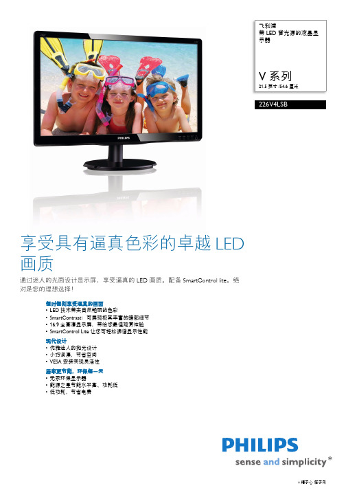
飞利浦21.5寸显示器说明书
• OSD 语言 : 英语 , 法语 , 德语 , 意大利语 , 葡萄 牙语 , 俄语 , 简体中文 , 西班牙语 , 土耳其语
机壳
• 颜色 : 黑色 • 表面 : 光面 (前边框) / 质地 (后盖)
•
SmartContrast 是飞利浦推出的一项技术,当观 看暗色调的视频或玩暗色调的游戏时,它会分析 所显示的内容,自动调节色彩并控制背光亮度, 从而实现对比度的动态增强,展现优异的数字画 面。选择 “ 节能 ” 模式时,经过微调的对比度和 背光可使日常办公应用程序呈现恰如其分的显示 效果,将功耗保持在较低水平。
率。它支持来自所有信号源的 1080p 信号,包括 最新的蓝光技术和先进的高清游戏控制台,为未
来做好了充分的准备。全面升级的信号处理功能
可支持更高的信号质量和分辨率。它可生成具有
出色的亮度和超凡的色彩的靓丽无闪烁的逐行扫
描图像。
不含汞
具有 LED 背光照明的飞利浦显示器不含汞物质, 汞是毒性最强的自然物质之一,可严重危害人体
SmartControl Lite
SmartControl Lite 是基于 GUI 显示器控制软件的 下一代 3D 代表。它允许用户通过鼠标精细调谐 大多数显示器参数,包括颜色、亮度、屏幕校 准、多媒体、 ID 管理等等。
SmartContrast
连接
• 信号输入 : VGA (模拟) , DVI-D (数字, HDCP)
能源之星 5.0
能源之星是美国环保局赞助的一项节能计划,该
计划同时也为许多其它国家所采纳。能源之星认
证确保您购买的产品符合最新的节能标准,并且
21.5,24寸触摸一体机参数报价
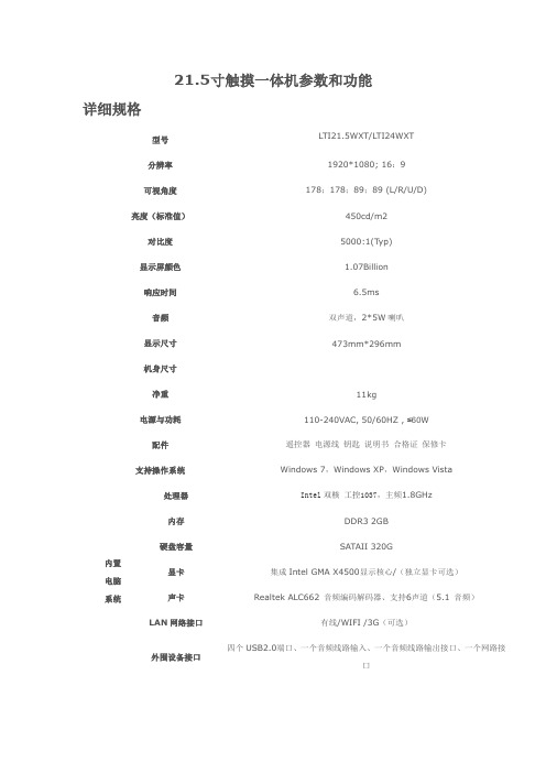
21.5寸触摸一体机参数和功能详细规格型号LTI21.5WXT/LTI24WXT分辨率1920*1080; 16:9可视角度178;178;89;89 (L/R/U/D) 亮度(标准值)450cd/m2对比度5000:1(Typ)显示屏颜色 1.07Billion响应时间 6.5ms音频双声道,2*5W喇叭显示尺寸473mm*296mm机身尺寸净重11kg电源与功耗110-240VAC, 50/60HZ , ≤60W 配件遥控器电源线钥匙说明书合格证保修卡支持操作系统Windows 7,Windows XP,Windows Vista内置电脑系统处理器Intel双核工控1037,主频1.8GHz内存DDR3 2GB硬盘容量SATAII 320G显卡集成Intel GMA X4500显示核心/(独立显卡可选)声卡Realtek ALC662 音频编码解码器、支持6声道(5.1 音频)LAN网络接口有线/WIFI /3G(可选)外围设备接口四个USB2.0端口、一个音频线路输入、一个音频线路输出接口、一个网路接口参考图片:报价:型号数量单价合计备注LTI21.5WX他 1 2950 2950 以上价格不含运费,不含税LTI24WXT 1 3100 3100 以上价格不含运费,不含税功能描述触摸嵌入方式:内置红外触摸屏书写面材质:4mm/5mm全钢化高防暴防眩光玻璃触摸屏感应方式嵌入式:光学影像触摸技术定位精度:±1.5㎜校准符合HID设备要求,无需校准多点触摸:支持Windows 7多点触摸和两人同时书写触摸次数:无限制触摸压力:无压力要求计算机响应系统:自动识别,无需安装驱动书写方式:手指、白板笔,或任意不透明物体触摸系统供电方式:可用USB直接供电。
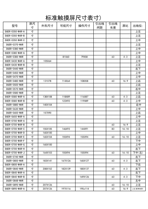
(膜对膜超薄触摸屏)标准触摸屏尺寸表(3.5-52寸)

(膜对膜超薄触摸屏)标准触摸屏尺⼨表(3.5-52⼨)标准触摸屏尺⼨表(3.5-52⼨)屏尺⼨外形尺⼨可视尺⼨操作尺⼨引出线间距引出线长度屏⽐出线位:3.5⼨76.5*63.4 71.4*55.3 71*54.9 1.0 63 4:3 上左3.5⼨87.8*53 78.2*44.3 77.8*43.9 1.0 63 16:9 上左3.5⼨81.3*54.8 75.1*47.6 75.1*47.6 1.0 63 16:9 上中3.7⼨82.51*63.27 78.03*57.17 78.03*57.17 1.0 63 4:3 上左3.8⼨83.5*67 79.4*59.479.4*59.4 1.0 63 4:3 上中3.8⼨83.1*66.4 74.1*55.7 72.1*53.7 1.0 63 4:3 上中3.85⼨91.3*72 81*60 79*58 1.0 63 4:3 上左4.3⼨105*64 97.8*56.7 97.8*56.7 1.0 63 16:9 上中4.3⼨105.5*67.2 96.2*56.1 96.2*56.1 1.0 63 16:9 上左4.4⼨102.8*64.2 94.1*60.2 94.1*60.2 1.0 63 16:9 右下4.5⼨104.7*65.9 98.7*57.5 95.44*54.26 1.0 63 4:3 上中4.7⼨111*93.3 103.4*84.5 103.4*84.5 1.0 63 4:3 上中4.8⼨131*78 114*64 108*58 2.54 63 16:9 上右5.0⼨119.2*90.8 108.1*79.9 108.1*79.9 1.0 63 4:3 上右5.7⼨132.5*104.8 124.6*95.9 116*88.3 1.0 63 4:3 右中5.8⼨144.5*88.7 127.9*72.9 127.9*72.9 1.0 63 16:9 上左5.8⼨138*108 118*89 116*87 2.54 63 4:3 上右5.8⼨135.5*103 122*92 119*89 2.54 63 4:3 上中5.88⼨140*104 122.1*93.3 119.2*90.3 2.54 63 4:3 右中6.3⼨149.7*89.4 142.6*81.3 142.2*80.96 1.0 63 16:9 上中6.5⼨157*90 141.1*78.1 140.7*77.7 1.0 63 16:9 上右6.5⼨155*89.2 145.4*80.93 142.4*77.93 1.0 63 16:9 上中7.0⼨165.5*99.8 158.9*89.7 158.5*89.3 1.0 63 16:9 上左7.0⼨164.5*103 160*94.5 158*92.5 2.54 63 16:9 上左7.0⼨155*105 146*93 144*91 1.2 83 16:10 上左7.0⼨165*100 155.6*87.6 155.2*87.2 1.0 63 16:9 上中7.0⼨165*104 155*94 155*94 1.0 63 16:10 上左7.0⼨164.8*99.8 153*86 152.4*84.4 1.0 63 16:9 下中7.0⼨165*100 155.6*87.6 155.2*87.2 1.0 63 16:9 上中7.0⼨164.8*103.8 153.5*93 151.5*91 1.0 63 16:10 右下7.0⼨164*103 155*94 155*94 1.0 63 16:10 下中(左)7.4⼨171.9*127.4 148.9*112.4 145.9*109.4 2.54 63 4:3 右下8.0⼨183*141 167*126 165*127 2.54 63 4:3 右下8.0⼨192.8*116.9 180.1*103.4 176.64*99.36 2.54 63 16:9 下右8.4⼨208*152 182*139 180*137 2.54 63 4:3 右下8.4⼨183.4*139.5 181.7*174.4 181.7*174.4 2.54 63 4:3 右下8.4⼨185*149.3 174.5*132 169*126 2.54 63 4:3 下中8.48⼨188.9*141.7 174*131.5 172*129.5 2.54 63 4:3 左中8.9⼨207*126 201.5*120 201.5*120 1.0 63 16:10 上左8.9⼨207*126 197*116 195*114 1.0 63 16:9 上左(配奇美屏)9.4⼨225.5*170.5 202.3*154.6 202.3*154.6 2.54 63 4:3 上左10⼨233*144 222.1*131.1 221.5*130.5 1.0 63 16:10 上右10⼨225.6*170.6 206.5*156.5 204*155 2.54 63 4:3 上右10.1⼨235*145.8 220.4*129.1 220.4*129.1 1.0 63 16:9 左上10.1⼨234*142 226.5*129 224.5*127 1.0 63 16:9 左上10.2⼨235*145.8 225.4*135.9 222*132.48 1.0 63 16:10 上左10.2⼨235*145.8 225.4*135.9 222*132.48 2.54 63 16:10 上左10.2⼨235*145.8 225.4*135.9 222*132.48 1.0 63 16:10 上左10.2⼨235*145.8 222.6*133.6 220.6*131.5 1.0 63 16:10 上左10.2⼨235*145.8 224*135.5 222*132.5 1.0 63 16:10 下右10.4⼨223*171211.4*159.4 211*159 2.54 63 4:3 右下10.4⼨234*178 216*163.4 216*163.4 2.54 63 4:3 右中10.5⼨236.5*180 216*164212*160 2.54 63 4:3 右中10.7⼨228.2*175.2 216.7*165.2 216.7*165.2 2.54 63 4:3 右中11⼨258.8*155 246*140 244*138 2.54 63 16:9 下右12.1⼨271*206 254*192 248*186 2.54 63 4:3 左中12.1⼨276.4*179.6 263.52*165.6 263.52*165.6 2.54 63 16:10 右中12.1⼨275.8*178 263.8*165.8 261.1*163.2 2.54 63 16:10 右中12.1⼨265*200 250*185 244.5*183.5 2.54 63 4:3 左上12.1⼨260*192 250*185 244.5*183.5 2.54 63 4:3 左上12.3⼨301.5*174.5 277.8*149 277.8*149 2.54 63 16:9 上左13⼨285*215 274*204 270*200 2.54 63 4:3 右上13.3⼨299*195 288.88*181.6 286.48*179.2 2.54 63 16:10 上右13.3⼨292*216 274.3*206 272.3*204 2.54 63 4:3 右中14.3⼨298*227 289*218 285*214 2.54 63 4:3 右中15.1⼨322*247 310*235 308*233 2.54 63 4:3 右中15.4⼨343.6*221.6 333.2*209.6 331.2*207.6 2.54 63 16:10 上右15.6⼨359.3*209.5 348.43*197.1 344.2*193.5 2.54 63 16:9 下右17.1⼨355*288 341.5*275 333.5*267 2.54 63 4:3 上右17⼨360*278 340*260 340*260 2.54 63 4:3 右中(CRT专⽤) 17⼨355*293 339*271 335*267 2.54 63 4:3 左上17.1⼨389*255 371*233 369.4*231.4 2.54 63 16:10 上右17.1⼨355*288 341.5*275 333.5*267 2.54 63 4:3 右下17.3⼨398*233 382*214 379*211 2.54 63 16:9 下中18.5⼨420*248 410*233 407*229 2.54 63 16:9 下右19⼨396*323 377*304 375*300 2.54 63 4:3 右中19⼨426.4*266.5 410.4*256.5 406.4*252.5 2.54 63 16:9 右中19⼨428*278 417*263 407.4*254.1 2.54 63 16:10 下右19⼨420*273 411*260 407.4*254.1 2.54 63 16:10 下右21.1⼨430*322 413*311 408*306 2.54 63 4:3 右中21⼨501*297 481.5*272.5 477.4*268.4 2.54 63 16:9 右中21.3⼨448*340 432*323 432*323 2.54 63 4:3 右中21.5⼨495*292 479.8*271.3 476*268 2.54 63 16:9 右中22⼨493.7*320 473.7*296 470×293 2.54 63 16:10 右中23.6⼨542*318 525.5*297 521*293 2.54 63 16:9 右中24⼨546*352 522*328 516*322 2.54 63 16:10 右中26⼨596*354 580.8*328 576*324 2.54 63 16:9 下中32⼨719.6*414.3 703.6*398.3 697.6*392.2 2.54 63 16:9 下中(右)37⼨843.8*485.4 827.8*469.4 819.6*460.8 2.54 63 16:9下右42⼨956*548 938*531 930*523 2.54 63 16:9 下右46⼨1043.5*597.4 1027.5*581.4 1019.5*573.4 2.54 63 16:9 下右52⼨1177*673 1161*657 1152*648 2.54 63 16:9 下右注:以上触摸屏有两种结构:1.胶⽚对胶⽚(膜对膜,F/F),超薄、打不碎触摸屏,总厚度为:0.5MM2.胶⽚对玻璃(F/G)总厚度为:1.4MM及2.3MM。
21.5寸显示器最佳分辨率是多少
21.5寸显示器最佳分辨率是多少21.5寸显示器最佳分辨率是多少?21.5寸显示器分辨率按照市场的默认的比例分2种,即宽屏16:10和宽屏16:9的比例,最佳分辨率分分别是16:10的分辨率是 1680*1050,16:9的最佳分辨率是1920*1080。
液晶显示的每一个像素点只能显示一组数码信号,而每一个像素点的点距也是一个标准,如果不能按照便准的比例来显示势必造成显示画面扭曲的现象。
看看你的系统设定里面是否出现了1680*1050(16:10)和1920*1080这两种显示分辨率的任意一种,如果出现了就说明你的显示器没有使用错误的分辨率,这个分辨率即为最佳的显示分辨率,高于或者低于这个分辨率都会造成显示不正常的现象。
但是如果没有这两分辨率则很有可能说明是显示驱动没有安装好。
这样就必须安装显卡驱动,直到出现最佳分辨率的想想才可以。
每一个品牌的显示器都配有自己的驱动,默认情况下不需要安装,如果需要安装,可以在显示器的包装中找到驱动盘。
液晶显示器的刷新频率,就使用操作系统默认的60hz,不要改(不管系统默认多少都不要改)。
lcd不是crt显示器,它的内部不是阴极射线管,不是靠电子枪去轰击显像管上的磷粉产生图像。
lcd显示器是靠后面的灯管照亮前面的液晶面板而被动发光,只有亮与不灯、明与暗的区别。
所以,液晶显示器没有电子枪逐行及隔行扫描屏幕的原理(lcd显示器工作时,每个像素点自始至终都发光,不存在闪烁的现象),也就不存在刷新频率的概念,改不改都一个样,刷新频率对所有的lcd均不起作用。
显示卡对显示器有自适应功能,当你插上液晶显示器后,显卡的刷新频率选项便自动不起作用,从而保护液晶显示器。
所以在windows下,你就不可能调到85hz。
这是最基本的常识。
这就是为什么没有液晶显示器的刷新频率可以调到85hz的原因。
最新整理21寸显示器长宽是多少
21寸显示器长宽是多少显示器通常也被称为监视器,不同尺寸的显示器,它的长度和宽度是不一样的。
那么你知道21寸显示器的长度和宽度分别为多少吗?下面就让学习啦小编来告诉你21寸显示器长宽是多少吧。
21寸显示器的长和宽21寸是指的对角的长度,换算成厘米大概是54c m(1英寸=2.54c m),市面上一般有两种16:9和4:3,16:9的是宽屏也是当下主流显示比例业内称21.5寸,屏幕尺寸一般47.6C M x26.8.C M。
4:3的是普屏21寸屏幕尺寸一般是40c m x30c m,市面几乎看不到了一般用在安防设备。
具体到整个显示器长宽高各品牌细节就更不相同,以三星E2220为例513.2309.661.9m m(不含底座),如果是窄边或无框长宽就更短些。
各品牌不一样,以三星E2220为例513.2309.661.9m m(不含底座)513.2388.5200m m(包含底座)586136386m m(包装)你说的标屏是4:3的吧,21寸没有。
显示器(d i s p l a y)通常也被称为监视器。
显示器是属于电脑的I/O设备,即输入输出设备。
它是一种将一定的电子文件通过特定的传输设备显示到屏幕上再反射到人眼的显示工具。
21寸/21.5寸显示器最佳分辨率21.5寸显示器分辨率,按照市场的默认比例分2种,宽屏16:10和宽屏16:9的比例,最佳分辨率分别是1680*1050(16:10)和1920*1080(16:9)。
液晶显示的每一个像素点只能显示一组数码信号,而每一个像素点的点距也是一个标准,如果不能按照便准的比例来显示势必造成显示画面扭曲的现象。
看看你的系统设定里面是否出现了1680*1050(16:10)和1920*1080这两种显示分辨率的任意一种,如果出现了就说明你的显示器没有使用错误的分辨率,这个分辨率即为最佳的显示分辨率,高于或者低于这个分辨率都会造成显示不正常的现象。
但是如果没有这两分辨率则很有可能说明是显示驱动没有安装好。
魅湃21.5寸电子班牌规格书
MY215-001 21.5寸壁挂液晶智能班牌规格书制作审核日期王少辉李易华20160816目录第一章产品概述 (3)1.1概述 (3)1.2功能特点 (3)1.3前景展望 (3)第二章产品组成2.1外壳 (4)2.2电路主板 (4)2.3液晶屏 (5)2.4摄像头 (5)2.5读卡器 (5)2.6其他说明 (5)第三章设备尺寸图 (6)第四章设备实拍 (8)第五章注意事项 (9)5.1严禁雨天放置室外 (9)5.2严禁遮盖保持阴凉 (9)1.1概述目前,液晶智能班牌主要服务于中小学以及高中等教学机构,借助软件,既能便于家长了解幼儿动态、防止被遗落而发生意外事故,又能便于老师和园长进行教学管理,同时,还能便于幼儿园与家长进行互动而诞生的一款高端科技产品。
1.2功能特点液晶智能班牌备有线网络、WIFI网络、刷卡、播报语音以及高清摄像的功能。
1.3前景展望目前,液晶智能考勤机主要应用于中小学等教学机构,随着市场的变化,未来将在各种教学机构普及。
2.1外壳液晶智能考勤机采用钢化玻璃与无辐射、抗干扰的金属结合而成,钢化玻璃能有效防止设备发生意外情况而破碎时划伤他人。
默认颜色为黑色,其他颜色可定制。
2.2电路主板CPU RK3288,四核内存2G内置存储器8G内置ROM2KB EEPROM解码分辨率最高支持1080P操作系统Android4.X以上播放模式支持循环、定时、插播等多种播放模式网络支持以太网、支持WiFi/蓝牙4.0、无线外设扩展视频播放支持wmv、avi、flv、rm、rmvb、mpeg、ts、mp4等图片格式支持BMP、JPEG、PNG、GIF音视频输出支持左右声道输出,内置双4R/20W,8R/10W功放RTC实时时钟支持定时开关机支持系统升级支持本地SD,USB升级2.3液晶屏液晶屏尺寸21.5寸显示区域392.256(V)*697.685(H)分辨率1920*1080px显示色彩16.7M亮度250cd/㎡视角(上下/左右)178°/178°相应时间5ms2.4摄像头采用200万像素、150度超大广角的摄像头,以保证照片的清晰度以及人物辨识度。
21.5寸电子班牌规格书-触屏版
语言
OSD
简中/英语
附件
电源线
×1
壁挂支架
×1
合格证
×1
说明书
×1
保修卡
×1
第二章
2.
触摸参数
触摸类型
投射式电容屏
触摸点数
10点
触控压力
<10g
透光率
>92%
连接方式
FPC
响应速度
≤10ms
最小识别点大小
5mm×5mm
最小触点移动检测
1mm
抗光性
具有抗光性
寿命
60000小时
R/L 178 (Min.), U/D 178 (Min.)
寿命
50,000 hrs(min.)
可视面积
476.6mm×268.1mm
帧频率
60Hz
电压供应
5V
安卓配置
CPU
RK3288四核1.8GHzCortex-A17
内部缓存容量(RAM)
2GB
内部存储容量(ROM)
8GB
系统版本
Android5.1
RTC实时时钟
支持 Support
系统升级
支持本地SD,USB升级
外设
摄像头
内置200万高清摄像头支持人脸识别
ARM CortexA7
拾音器
内置高音质麦克风
读卡器
内置IC/ID双频读卡器
电源
电压
100V~240V,50-60Hz
额定功耗
≤35W
待机功率
≤1W
环境
工作温度
0℃~50℃
储藏温度
-20℃~60℃
输入接口
21.5寸触摸平板电脑1037U
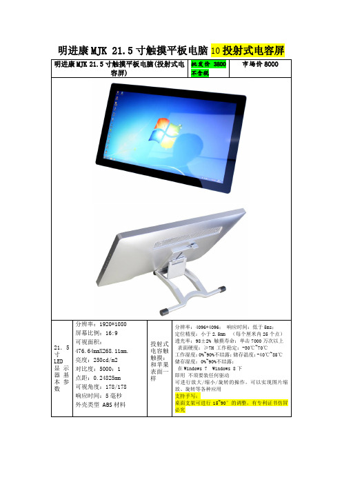
明进康MJK21.5寸触摸平板电脑(投射式电容屏)
批发价3800不含税
市场价8000
21.5寸LED显示器基本参数
分辨率:1920*1080
屏幕比例:16:9
可视面积:476
对比度:5000:1
点距:0.24825mm
可视角度:178/178
响应时间:5毫秒
外壳类型ABS材料
投射式电容触触摸:和苹果表面一样
分辨率:4096*4096;响应时间:低于5ms;
定位精度:小于2.5mm(每个厘米内25个点)
透光率:98±2%触摸寿命:单击7000万次以上
表面硬度:≥7H工作稳定:-30℃~70℃
工作湿度:0%~90%不结露;储存温度:-40℃~85℃
内存:DDR32G
硬盘:320G/540000转
外置:1*HDMI接口1*VGA接口4*USB接口1*12VDC输入接口1*RJ45接口1*音频I/O接口
尺寸、重量
物理尺寸: 536mmX328mmX50mm
包装尺寸: 635mmX187mmX445mm
重量;8.5kg
不含运费不含税含税加8%不须要底坐每台少50元
储存湿度:0%~90%不结露;
在Windows 7 Windows 8下
即用不须要装任何驱动
可进行放大/缩小/旋转的操作。可以实现图片缩放、旋转等各种应用
支持手写;
桌面支架可进行15~90°的调整。有专利证书仿冒必究
PC配置
CPU: inter Atom双核1037U 1。8
显卡:IntelGMA3650显卡
亿科 21.5寸AUO M215HTN01.1(68颗4014灯)模组规格书

文件名称BLU Purchase Specification模组规格书页次1 / 13产品名称215W-3TLED单侧背光版次1.1规格书Specification Sheet 客戶 :(Customer Name) _品名:( Material Name)料号:(Material Number)料号:(Customer Material Number)客户承认CustomerApproved by承认Checked by审核Approved by承认Checked by审核Designed by编写亿科承认AU OPTRONICS CORPORATIONProduct Specification M215HTN01.1() Preliminary Specification(V) Final SpecificationModule 21.5” Color TFT-LCDModel Name M215HTN01.1 open cellCustomer DateApproved byNote: This Specification is subject to change without notice. Approved by Date Howard Lee2012/10/22 Prepared byLouis Jung2012/ 10/22 AU Optronics corporation3.0 Functional Block DiagramThe following diagram shows the functional block of the21.5 inch Color TFT-LCD Module:I/F PCB Interface:P-TWO AL230F-A0G1D-PSTM MSCKT2407P30HBMating Type:FI-X30HL (Locked Type)5.0 Electrical characteristics 5.1 TFT LCD Module 5.1.1 Power SpecificationInput power specifications are as following:Note 1: Measurement conditions:The duration of rising time of power input is 470us.Symbol Parameter Min Typ Max Unit ConditionsVDDLogic/LCD DriveVoltage 4.5 5.0 5.5 [Volt] +/-10%- 1.13 1.36 [A] VDD= 5.0V, All Black Pattern At 60HzIDDInput Current1.34 1.61 [A] VDD= 5.0V, All Black Pattern At 75Hz- 5.65 6.80 [Watt] VDD= 5.0V, All Black Pattern At 60HzPDDVDD Power6.7 8.05 [Watt] VDD= 5.0V, All Black Pattern At 75Hz IRushInrush Current --3[A]Note 1VDDrpAllowable Logic/LCD Drive Ripple Voltage-- 500 [mV] p-pVDD= 5.0V, All Black Pattern At 75Hz6.3 Signal DescriptionPIN # SIGNAL NAME DESCRIPTION1 RxO0- Negat ive LVDS differential data input (Odd data)2 RxO0+ Positive LVDS differential data input (Odd data)3 RxO1- Negat ive LVDS differential data input (Odd data)4 RxO1+ Positive LVDS differential data input (Odd data)5 RxO2- Negat ive LVDS differential data input (Odd data)6 RxO2+ Positive LVDS differential data input (Odd data)7 GND Power Ground8 RxOCLK- Negat ive LVDS differential clock input (O dd clock)9 RxOCLK+ Positive LVDS differential clock input (O dd clock)10 RxO3- Negat ive LVDS differential data input (Odd data)11 RxO3+ Positive LVDS differential data input (Odd data)12 RxE0- Negat ive LVDS differential data input (Even data)13 RxE0+ Positive LVDS differential data input (Even data)14 GND Power Ground15 RxE1- Negat ive LVDS differential data input (Even data)16 RxE1+ Positive LVDS differential data input (Even data)17 GND Power Ground18 RxE2- Negat ive LVDS differential data input (Even data)19 RxE2+ Positive LVDS differential data input (Even data)20 RxECLK- Negat ive LVDS differential clock input (Even clock)21 RxECLK+ Positive LVDS differential clock input (Even clock)22 RxE3- Negat ive LVDS differential data input (Even data)23 RxE3+ Positive LVDS differential data input (Even data)24 GND Power Ground25 NC No connection (for AUO test only. Do not connect)26 NC No connection (for AUO test only. Do not connect)27 NC No connection (for AUO test only. Do not connect)28 VDD Power +5V29 VDD Power +5V30 VDD Power +5VNote 1: Input signals of odd and even clock shall be the same timing.灯条串并定义及接口型号定义:4.. BACKLIGHT UNITValue Parameter Symbol Min. Typ.Max. UnitNote LED Light Bar Input Voltage Per Input PinVPIN -- 56(1), Duty=100%, IPIN=(60mA)IPIN --mA (1), (2) Duty=100%LED Life Time LLED 30000Hrs(3) Power ConsumptionPBL--(9.2)W(1)Duty=100%, IPIN=(60mA)Note (1) LED light bar input voltage and current are measured by utilizing a true RMS multimeter as shownbelow:Note (2) PBL = IPIN × VPINNote (3) The lifetime of LED is defined as the time when LED packages continue to operate under theconditions at Ta = 25 ±2 к and I= (25)mA (per chip) until the brightness becomes Љ 50% of its original value.灯条总电流I230240------V4014(60MA)灯珠 17串4并Figure 1. Measurement Set Up(L =50cm)Figure 2. White Luminance and Uniformity Measurement Locations (9 points) 192 960 17285409727.1.1 Pin AssignmentPin# Signal Name Pin# Signal Name 1 RxO0- 2 RxO0+ 3 RxO1- 4 RxO1+ 5 RxO2- 6 RxO2+ 7 GND 8 RxOCLKIN- 9 RxOCLKIN+ 10 RxO3- 11 RxO3+ 12 RxE0- 13 RxE0+ 14 GND 15 RxE1- 16 RxE1+ 17 GND 18 RxE2- 19 RxE2+ 20 RxECLKIN- 21 RxECLKIN+ 22 RxE3- 23 RxE3+24 GND25NC (for AUO test only. Do not connect)26 NC (for AUO test only. Do not connect) 27 NC (for AUO test only. Do not connect) 28 VDD 29VDD30VDD环境温度(Ta)=25℃±2 湿度HR=65%±10項目 Item單位unit規 格 Spction 备注 RemarkMINTYPMAXCenter point(NOTE 1)1模组亮度BLU BrightnessCenter point cd/m 2250 --- 均匀性Uniformity 9点(NOTE2) 2模组色度LCM CIEx --- -0.030 0.313 +0.030 Center point y --- -0.030 0.329 +0.030Center point中心点为最亮点 The center brightness data ia the maximum下图示中9点之最小数值点比中心点,均匀性定义:Minimum(1-9)/Maximum(5)mum value of 9 point divided by the center ,------75---8.0 Reliability TestEnvironment test conditions are listed as following table.Items Required Condition Note Temperature Humidity Bias (THB) Ta= 50,℃80%RH, 300hoursHigh Temperature Operation (HTO) Ta= 50,℃50%RH, 300hoursLow Temperature Operation (LTO) Ta= 0, 300hours℃High Temperature Storage (HTS) Ta= 60, 300hours℃Low Temperature Storage (LTS) Ta= -20, 300hours℃Vibration Test (Non-operation) Acceleration: 1.5 GrmsWave: RandomFrequency: 10 - 200 HzSweep: 30 Minutes each Axis (X, Y, Z)Shock Test (Non-operation) Acceleration: 50 GWave: Half-sineActive Time: 20 msDirection: ±X,±Y,±Z (one time for each Axis)Drop Test Height: 60 cm, package testThermal Shock Test (TST) -20/℃30min, 60/℃30min, 100 cycles 1 On/Off Test On/10sec, Off/10sec, 30,000 cyclesContact Discharge: ± 15KV, 150pF(330Ω ) 1sec,8 points, 25 times/ point.ESD (Electro Static Discharge)Air Discharge: ± 15KV, 150pF(330Ω ) 1sec8 points, 25 times/ point.2Altitude Test Operation:18,000 ft Non-Operation:40,000 ftNote 1: The TFT-LCD module will not sustain damage after being subjected to 100 cycles of rapid temperature change. A cycle of rapid temperature change consists of varying the temperature from -20℃to 60℃, and back again. Power is not applied during the test. After temperature cycling, the unit is placed in normal room ambient for at least 4 hours before power on.Note 2: EN61000-4-2, ESD class B: Certain performance degradation allowedNo data lostSelf-recoverableNo hardware failures.P。
21寸显示器长宽是多少
21寸显示器长宽是多少显示器通常也被称为监视器,不同尺寸的显示器,它的长度和宽度是不一样的。
那么你知道21寸显示器的长度和宽度分别为多少吗?下面就让小编来告诉你21寸显示器长宽是多少吧。
21寸显示器的长和宽21寸是指的对角的长度,换算成厘米大概是54cm(1英寸=2.54cm),市面上一般有两种16:9和4:3,16:9的是宽屏也是当下主流显示比例业内称21.5寸,屏幕尺寸一般47.6CM x 26.8.CM。
4:3的是普屏21寸屏幕尺寸一般是40cmx30cm,市面几乎看不到了一般用在安防设备。
具体到整个显示器长宽高各品牌细节就更不相同,以三星E2220为例513.2×309.6×61.9mm(不含底座),如果是窄边或无框长宽就更短些。
各品牌不一样,以三星E2220为例513.2×309.6×61.9mm(不含底座) 513.2×388.5×200mm(包含底座) 586×136×386mm(包装)你说的标屏是4:3的吧,21寸没有。
显示器(display)通常也被称为监视器。
显示器是属于电脑的I/O设备,即输入输出设备。
它是一种将一定的电子文件通过特定的传输设备显示到屏幕上再反射到人眼的显示工具。
21寸/21.5寸显示器最佳分辨率21.5寸显示器分辨率,按照市场的默认比例分2种,宽屏16:10和宽屏16:9的比例,最佳分辨率分别是1680*1050(16:10)和1920*1080(16:9)。
液晶显示的每一个像素点只能显示一组数码信号,而每一个像素点的点距也是一个标准,如果不能按照便准的比例来显示势必造成显示画面扭曲的现象。
看看你的系统设定里面是否出现了1680*1050(16:10)和1920*1080这两种显示分辨率的任意一种,如果出现了就说明你的显示器没有使用错误的分辨率,这个分辨率即为最佳的显示分辨率,高于或者低于这个分辨率都会造成显示不正常的现象。
友达21.5寸消费类液晶屏P215HVN01.0-商规屏-21.5寸屏资料

TFT液晶屏:P215HVN01.0P215HVN01.0是友达光电股份有限公司(友达,AUO) 推出的一款采用a-Si TFT-LCD技术的21.5英寸液晶模组产品,它装配有WLED背光,无背光驱动,无触摸。
根据友达(AUO)于2015年12月1日发布的版本号为Ver0.2的产品规格书,P215HVN01.0显示分辨率为1920(RGB)×1080 (FHD),宽高比为16:9 (宽:高),像素采用RGB垂直条状排列。
它的显示区域尺寸为476.64×268.11 (宽×高) mm,可视尺寸为479.8×271.31 (宽×高) mm,外观尺寸为495.6×292.2 (宽×高)×11(厚) mm,表面处理为雾面,Hard coating (3H),产品净重1.67Kgs (Typ.)。
背光方面此产品采用了15S4P WLED发光的侧入式光源(底部),光源的使用寿命为30K小时,不含背光驱动。
P215HVN01.0采用了LVDS (2 ch, 8-bit)TFT液晶屏: 信号接口,总共30 pins,采用端子连接,驱屏电压为5.0V (Typ.)。
它的典型垂直刷新率Fv为60Hz。
如果开发新产品想采用P215HVN01.0液晶模组,屏库®建议您向友达(AUO)或其代理商了解关于P215HVN01.0的最新的生产状态信息和技术信息。
屏库®上所显示的面板参数均由屏库电子工程师依据规格书录入,已尽力减少错误,但不能保证参数的完全正确。
请以规格书为准!根据屏库掌握的情报此产品于2016年Q1量产,当前生产状态为量产中。
目前P215HVN01.0在屏库上有9条现货信息、15家供应商信息,属于目前屏库市场交易的主力型号产品。
屏库于2016年07月20日对此型号首次建立参数,并于2018年08月10日对参数进行了最后更新。
21.5寸壁挂式广告机规格书
M1421501 21.5寸壁挂式广告机
规格书
目录
第一章产品概述 (3)
1.1概述 (3)
1.2功能特点 (3)
1.3产品特点 (3)
第二章产品组成
2.1电路主板 (4)
2.2外壳 (4)
2.3液晶屏 (5)
第三章设备尺寸图 (5)
第四章设备效果图 (6)
1.1概述
广告机,是属于当下商显行业流行且具备潜力的产品,其操作系统可随着内部配置的变化而随时调整,适用于多种行业,用途非常广泛,是一款前途不可限量的、具有爆发力的智能产品。
1.2 功能特点
广告机具备连接网络(包括有线、无线网络,4G网络可额外付费添加)、视频播放、图片展示以及上网等功能。
1.3产品特点
2.1 电路主板
2.2 外壳
液晶广告机采用钢化玻璃与无辐射、抗干扰的金属结合而成,钢化玻璃能有效防止设备发生意外情况而破碎时划伤他人。
默认玻璃颜色为黑色,其他颜色可定制。
2.3 液晶屏
第三章设备尺寸图
第四章设备效果图。
京东方21.5寸液晶屏HR215WU1-210规格书-杭州旭虹科技有限公司
3.0
4.0 5.0 6.0 7.0 8.0 9.0 10.0 11.0 12.0 13.0 14.0 15.0
Electrical Specifications
Optical Specifications Interface Connection Signal Timing Specifications Signal Timing Waveforms of Interface Signal Input Signals, Display Colors & Gray Scale of Colors Power Sequence Mechanical Characteristics Reliability Test Handling& Cautions Product Serial Number Packing Appendix
1.1 Introduction HR215WU1-210 is a color active matrix TFT LCD module using amorphous silicon TFT's (Thin Film Transistors) as an active switching devices. This module has a 21.5 inch diagonally measured active area with FHD resolutions (1920 horizontal by 1080 vertical pixel array). Each pixel is divided into RED, GREEN, BLUE dots which are arranged in vertical stripe and this module can display 16.7M colors. The TFT-LCD panel used for this module is adapted for a low reflection and higher color type.
21.5 OPEN CELL 规格书LM215DA-T03_Open Cell Final Specification_V1 1

TO:规格书编号 File No. 作成日 Issue Date: 改订日 Revision Date:PN-RD-0004A2011 年(Y)11 月(M)16 日(D) 2012 年(Y)07 月(M)23 日(D)《新规 New·变更》 Revision产 品 规 格 书Product Specification产品名 Product 机种名 Model【接收印栏】TFT-LCD Open cellLM215DA-T03※ 本基准书由封面、附件等全 18 页构成。
如果对该规格书有异议,请在下订单前提出。
※ This Product Specification have 18 pages including the coversheet and Appendices. Please negotiate the objection point before purchase order.中电熊猫集团 南京中电熊猫液晶显示科技有限公司 研发中心 设计整合部 CEC PANDA GROUP NANJING CEC PANDA LCD TECHNOLOGY CO., LTD. R&D CENTER, DESIGN INTEGRATION SECTION.PANDA- CONTENTS REVISION HISTORY 1. GENERAL DESCRIPTION1.1 OVERVIEW 1.2 CHARACTERISTICSLM215DA-T03 Specification Version 1.1--------------------------------------------------------3 --------------------------------------------------------42. ABSOLUTE MAXIMUM RATINGS2.1 ABSOLUTE RATINGS OF ENVIRONMENT--------------------------------------------------------43. ELECTRICAL CHARACTERISTICS3.1 ABSOLUTE MAXIMUN RATING 3.2 CONTROL CIRCUIT DRIVING--------------------------------------------------------54. INPUT TERMINAL PIN ASSIGNMENT4.1 TFT LCD OPEN CELL 4.2 BLOCK DIAGRAM (OPEN CELL) 4.3 LVDS INTERFACE 4.4 COLOR DATA INPUT ASSIGNMENT--------------------------------------------------------75. INTERFACE TIMING5.1 INPUT SIGNAL TIMING SPECIFICATIONS-------------------------------------------------------116. OPTICAL CHARACTERISTICS6.1 OPTICAL SPECIFICATION-------------------------------------------------------127. DEFINITION OF LABELS7.1 OPEN CELL LABEL 7.2 CELL BOX LABEL-------------------------------------------------------148. Packing8.1 PACKING SPECIFICATIONS 8.2 PACKING METHOD-------------------------------------------------------159. PRECAUTIONS 10. RELIABILITY TEST ITEMS 11. MECHANICAL DRAWING-------------------------------------------------------15 -------------------------------------------------------17 -------------------------------------------------------172PANDALM215DA-T03 Specification Version 1.1REVISION HISTORYMODEL NO: LM215DA-T03DATENO.REVISED No.PAGESUMMARYNOTE2011/11/16PN-RD-0004AT1.0181 issuestTentative2012/04/10 PN-RD-0004AV1.0P4 Confirm the value of weight. P5 Add value of IRush and delete Trush. 4,5,14, P14 Update the format of packing label. P15 Update the specification of packing. 15 Change the figure of packing method.Final Version2012/07/23 PN-RD-0004AV1.15P5.Modify the Spec. of t5 .Final Version3PANDA1. GENERAL DESCRIPTION1.1 OVERVIEWLM215DA-T03 Specification Version 1.1This module is color active matrix LCD Open-cell incorporating amorphous silicon TFT (Thin Film Transistor). It is composed of a color TFT-LCD panel, driver ICs, PWB. Graphics and texts can be displayed on a 1920×RGB×1080 dots panel with about 16.7M colors (R/G/B 6bits+Hi FRC data in each color) by using LVDS(Low Voltage Differential Signaling) to interface, +5V of DC supply voltage.1.2 CHARACTERISTICSCHARACTERISTICS ITEMS Screen Diagonal [in] Pixels [lines] [mm] [mm] Active Area Pixel Pitch SPECIFICATIONS 21.5” 1920×1080 476.64 (H) x 268.11 (V) 0.24825 (H) x 0.24825 (V) RGB vertical stripe 585 487.54(W) x 335.81(H) x 3(D) Typ. 487.54(W) x 282.91(H) x 1.83(D) Typ Normally White Anti-glare,3HPixel Arrangement Weight [g] Physical Size(COF/PWB included) TFT glass Size [mm] Display Mode Surface treatment (Without the protection film)[mm]2. ABSOLUTE MAXIMUM RATINGS2.1 ABSOLUTE RATINGS OF ENVIRONMENTItem Storage Temperature Operating Ambient Temperature Altitude Operating Altitude Storage Shelf life: one year [Note 1] Temperature and relative humidity range is shown in the figure below. *1) 80 %RH Max. (Ta ≦ 40 ºC). *2) Wet-bulb temperature should be 40 ºC Max. (Ta > 40 ºC). Symbol TST TOP A OP A ST Value Min. -20 0 0 0 Max. +60 50 5000 12000 Unit ºC ºC M M Note [Note 1,3] [Note 1,2,3] [Note 3] [Note 3]Storage Condition: With shipping package.*3) No condensation. 4PANDALM215DA-T03 Specification Version 1.1[Note 2] The maximum operating temperature is based on the test condition that the surface temperature of display area is less than or equal to 50ºC with LCD module alone in a temperature controlled chamber. Thermal management should be considered in your product design to prevent the surface temperature of display area from being over 60ºC. The range of operating temperature may degrade in case of improper thermal management in your product design. [Note 3] The rating of environment is base on LCD module. Leave LCD cell alone, this environment condition can’t be guaranteed. Except LCD cell, the customer has to consider the ability of other parts of LCD module and LCD module process.3. ELECTRICAL CHARACTERISTICS3.1 Absolute Maximum RatingParameter +5V supply voltage Storage temperature Operation temperature Symbol VCC Tstg Topa Condition Ta=25℃ Ratings 0~+6 -20~+60 0~+50 Unit V ℃ ℃ Remark3.2 Control circuit drivingParameter Supply voltage +5V supply voltage Current dissipation Symbol VCC ICC IRush VRP VTH VTL Min 4.5 — — — — -100 Typ 5.0 820 — — — — — 1.2 4.1 Max 5.5 900 3 100 100 — 600 1.5 4.5 Unit V mA A mVp-p mV mV mV V W Remark [Note 1] VCC=5.0V,60Hz Black Pattern [Note 2] VCC=5.0V VCM=1.2V [Note 3]Permissible input ripple voltage High Differential Input Threshold Voltage Low Input Differential Voltage Differential Input Common Mode Voltage∣VID∣ 100 VCM P 1.0 —Power consumption[Note1] Power, data sequence 0.50ms≦t1≦10ms 0.01ms<t2≦50ms 0.01ms<t3≦50ms[VCM]: Common mode voltage of LVDS driver t4≧1 sec t5≧500ms t6≧200ms5PANDAVin=5.0V VCC=5.0V 4.5VLCD Power Supply Logic SignalLM215DA-T03 Specification Version 1.14.5V data 0.5V 0.5V0.5V t1 t2 VL t3t4Backlight Power Supplyt5t6Data: RGB DATA, DCLK, DENA※ Data: CLKIN±,RIN0±,RIN1±, RIN2±, RIN3± ※ About the relation between data input and back light lighting, please base on the above-mentioned input sequence. ※ When back light is switched on before panel operation or after a panel operation stop, it may not display normally. But this phenomenon is not based on change of an incoming signal, and does not give damage to a liquid crystal display. ※ VCC-dip conditions: (1) When 3.6V≦VCC(min)<4.5V, td≦10 ms (2) When VCC <3.6 V, VCC-dip conditions should also follow the VCC-turn-on conditions.[Note2] IRush Measurement Condition: The duration of rising time of power input is 470us.6PANDALM215DA-T03 Specification Version 1.1[Note3] RIN+: Positive differential DATA & CLK Input RIN -: Negative differential DATA & CLK InputRIN- RIN+ RIN+ RIN- GND VCM |VID|VTH VTL4. INTERFACE PIN CONNECTION4.1 TFT LCD OPEN CELLCN1 (Interface signals and +5V DC power supply) Shown on the next table. Using connector: FI-XB30SSRLA-HF-16 (JAE) or compatible Matching connector: FI-X30HL(JAE) or compatible Pin No. 1 2 3 4 5 6 7 8 9 10 11 12 Symbol RxOIN0RxOIN0+ RxOIN1RxOIN1+ RxOIN2RxOIN2+ GND RxOCLKRxOCLK+ RxOIN3RxOIN3+ RxEIN0Function Negative LVDS DATA input(ODD) Positive LVDS DATA input(ODD) Negative LVDS DATA input(ODD) Positive LVDS DATA input(ODD) Negative LVDS DATA input(ODD) Positive LVDS DATA input(ODD) Ground Negative LVDS Clock input(ODD) Positive LVDS Clock input(ODD) Negative LVDS DATA input(ODD) Positive LVDS DATA input(ODD) Negative LVDS DATA input(EVEN) LVDS LVDS LVDS LVDS LVDS Remark LVDS LVDS LVDS LVDS LVDS LVDS7PANDA13 14 15 16 17 18 19 20 21 22 23 24 25 26 27 28 29 30 RxEIN0+ GND RxEIN1RxEIN1+ GND RxEIN2RxEIN2+ RxCLKRxCLK+ RxEIN3RxEIN3+ GND NC NC NC VDD VDD VDD GroundLM215DA-T03 Specification Version 1.1Positive LVDS DATA input(EVEN) LVDSNegative LVDS DATA input(EVEN) Positive LVDS DATA input(EVEN) Ground Negative LVDS DATA input(EVEN) Positive LVDS DATA input(EVEN) Negative LVDS Clock input(EVEN) Positive LVDS Clock input(EVEN) Negative LVDS DATA input(EVEN) Positive LVDS DATA input(EVEN) Ground No connection(Do not connect) No connection(Do not connect) No connection(Do not connect) POWER +5V POWER +5V POWER +5VLVDS LVDSLVDS LVDS LVDS LVDS LVDS LVDS8PANDA4.2 Block Diagram (Open-cell)LM215DA-T03 Specification Version 1.0301CN1 Signal Source PWB Source Driver PowerINPUT SIGNAL: RxOIN0- , RxOIN0+ RxOIN1- , RxOIN1+ RxOIN2- , RxOIN2+ RxOCLK- , RxOCLK+ RxOIN3- , RxOIN3+ RxEIN0- , RxEIN0+ RxEIN1- , RxEIN1+ RxEIN2- , RxEIN2+ RxECLK- , RxECLK+ RxEIN3- , RxEIN3+ POWER: +5V DCLCD PANEL 1920 x 3(rgb) x 10804.3 LVDS INTERFACEDE: Display Enable NA: Not Available (Fixed Low) R/G/B Data 7:MSB , R/G/B Data 0:LSB , O : “First Pixel Data” E : “Second Pixel Data”9PANDA4.4 COLOR DATA INPUT ASSIGNMENTLM215DA-T03 Specification Version 1.00: Low level voltage, 1: High level voltage. Each basic color can be displayed in 256 gray scales from 8 bit data signals. According to the combination of total 24 bit data signals, the 16,7M colors display can be achieved on the screen.105. INTERFACE TIMING5.1 INPUT SIGNAL TIMING SPECIFICATIONS(a) The input signal timing specifications are shown as the following table and timing diagram.[Note]*1) DENA (data enable) usually is positive. *2) DCLK still inputs during blanking. *3) DE mode only.*4) It maybe cause flicker at 50Hz. (b) Timing ChartItem SymbolMin.Typ. Max. Unit LCDTimingDCLKFreq.fCLK 5572 90 MHzCycle tCLK18.1813.89 11.11 ns DENAHorizontal Horizontal effective timetHA 960960 960 tCLK Horizontal blank timetHB 32100 115 tCLK Horizontal total timetH 9921060 1075 tCLK VerticalVertical frame Rate Fr 5060 75 Hz Vertical total time tV 10841130 1170 tH Vertical effective time tVA 10801080 1080 tHVertical blank timetVB45090tH6. OPTICAL CHARACTERISTICS6.1 OPTICAL SPECIFICATIONTa=25°CParameter Symbol Condition Min. Typ. Max. Unit RemarkViewingangle rangeHorizontal θ21+θ22CR>1080 90 - Deg.[Note1,4]Verticalθ11+θ1255 65 - Deg. Contrast ratio CR θ =0 deg.400 600 - - [Note2,4] Response time Tr+Tf-5 8 ms[Note3,4]Chromaticity of white x 0.2830.3130.343- [Note 4]y 0.2990.3290.359- Chromaticity of red x 0.6160.6460.676-y 0.3170.3470.377-Chromaticity of green x 0.2920.3220.352- y 0.6000.6300.660- Chromaticity of bluex 0.1250.1550.185- y 0.0310.0610.091-*The measurement shall be executed 30 minutes after lighting at rating. *These values are measured with CPL standard back light unit.* The optical characteristics are measured using the following equipment.Measurement of viewing angle range, Response time.Measurement of Contrast, Luminance, Chromaticity.)[Note 1] Definitions of viewing angle range:Viewing angle[Note 2] Definition of contrast ratio:The contrast ratio is defined as the following.[Note 3] Definition of response timeThe output signals of photo detector are measured when the input signals are changed from “Full White” to “Full Black” (rising time, Tr), and from “Full Black” to “Full White” (falling time, Tf), respectively. The response time is interval between the 10% and 90% (1 frame at 60 Hz) of amplitudes.Response time=Tr + Tf[Note 4] This shall be measured at center of the screen.Normal lineContrast Ratio =Luminance (Brightness) with black screenLuminance (Brightness) with white screen7. DEFINITION OF LABELS7.1 OPEN CELL LABELThe label of displays, product model (LM215DA-T03), a product number is stuck on the Open-cell.7.2 CELL BOX LABELProduction date (YYYY/MM/DD)Model No. Barcode Box IDQuantity Model No.Serial numberProduction date (YYYY/MM/DD) Barcode8. PACKING8.1 PACKING SPECIFICATIONS(a)Piling number of EPS BOX : 2x2 columns, 6 rows(b)Packing quantity in one ESP BOX : 20 pieces(c)EPS BOX size : 660mm*445mm*143mm(d)Pallet size : 1346mm*925mm*150mm(e)Total mass of one EPS BOX filled with full Panel : 13.4 kg8.2 PACKING METHOD9. PRECAUTIONS(a)Because the Open-Cell is too weak to destroy by static electricity, please don’t touch the terminal with bare hands.(b)Front polarizer can easily be damaged. Pay attention on it.(c)Since long contact with drops of water may cause discoloration or spots, please wipe off them as soon as possible.(d)When the panel surface is soiled, wipe it with absorbent cotton or other soft cloth.(e)The Panel will be broken or chipped when it is dropped or bumped against a hard substance.(f)Precautions of peeling off the Protection Film:*1) Be sure to peel off slowly (recommended more than 7 sec.) and constant speed.*2) Peeling direction shown in the next Fig.*3) Be sure to ground person with adequate methods such as the anti-static wrist band.*4) Be sure to connect PWB to GND while peeling off the protection film.*5) Ionized air should be blown to the surface while peeling off the protection film.*6) The protection film must not touch drivers and PWB.After the protection film has been peeled off, some adhesive may be remained on the polarizer. Pleaseuse isopropyl-alcohol to remove it.(g)Since the Open-cell consists of TFT and electronic circuits with CMOS-ICs, which are very weak to electrostatic discharge, persons who are handling an Open-Cell should be grounded though adequate methods such as an anti-static wrist band. Connector pins should not be touched directly with bare hands. (h)Avoiding COF damage, do not bend PWB to display side when handling the open cell, recommend coating silicon or tuffy on front and back side of COF.Reference: Process control standard of CPL.item Management standard value and performance standard1 Anti-static mat(shelf) 1to50 [Mega ohm]2 Anti-static mat(floor, desk) 1to100 [Mega ohm]3 Ionizer Attenuate from ±1000V to ±100V within two seconds.4 Anti-static wrist band 0.8 to 10 [Mega ohm]5 Anti-static wrist band entry and ground resistance Below 1000 [ohm]℃6 Temperature 22 to 26 []7 Humidity 60 to 70 [%](i)Since the Open-cell has a PWB, please take care to keep it off any stress or pressure when handling or installing the Open-cell, otherwise some of electronic parts on them may be damaged.(j)Be sure to turn off the power supply when inserting or disconnecting the cable.(k)Be sure to design the module and cabinet so that the Open-cell van is installed without any extra stress such as warp or twist.(l)When handling and assembling Open-Cell into module, please be noted that long-term storage in the environment of oxidization or deoxidization gas and the use of materials such as reagent, solvent, adhesive, resin… etc, which generate these gasses, may cause corrosion and discoloration of the Open-Cell.(m)Applying too much force and stress to PWB and drivers may cause a malfunction electrically and mechanically.(n)The Open-cell has high frequency circuits. Sufficient suppression to EMI should be done by system manufactures.(o)Please be careful since image retention may occur when a fixed pattern is displayed for a long time.(p)The chemical compound, which causes the destruction of ozone layer, is not being used.(q)This Open-Cell module is corresponded to RoHS.(r)When any question or issue occurs, it shall be solved by mutual discussion.10. Reliability test itemsTest item ConditionHigh temperature storage test Ta= 60°C, 240h Low temperature storage test Ta=-20°C, 240hHigh temperature and high humidity operation test Ta= 50°C, 80%RH, 240h (No condensation)High temperature operation test Ta= 50°C, 240hLow temperature operation test Ta= 0°C, 240hESD(no operation) Contact discharge on LVDS connector ±200V(200PF,0Ω)[Result evaluation criteria]Under the display quality test condition with normal operation state, there shall be no change, which may affect practical display function.11. Mechanical Drawing。
LTM215HT05

LTM215HT05基本参数制造商(Productor)三星/SAMSUNG产品型号(MODEL)LTM215HT05屏尺寸(Size)21.5"分辨率(Resolution)1920×1080分辨率简称(Resolution Name)FHD显示比例(Display scale)16:9像素排列(Pixel Arrangement)RGB垂直条状点距(Pixel Pitch)0.08275×0.24825mm产品组成(Panel Composition)液晶屏,面板类型(Technology)a-Si TFT-LCD主要用途(Applications)【电脑显示器】,显著特征(Panel Features)【广色域】,【雾面】,【广视角】,【白光LED】, LTM215HT05光电参数显示模式(Display mode)TN,常白显示,透射式亮度(Luminance)250nits对比度(Contrast Ratio)1000:1颜色(Color)16.7M色彩饱和度(Color Saturation)72%NTSC(CIE1931)响应时间(Response)5ms可视角度(Viewing Angle)80/80/85/85(上/下/左/右)白场色度(White Field Chroma)X:0.313;Y:0.329白场变动(White Field Dynamic) 1.33(9points)扫描频率(Scanning Frequency)60Hz反转扫描(Reverse Scan)No信号类型大类(The kind of Singnal)LVDS接口类型(Interface)LVDS信号接口定义(Singnal Interface Definition)BLE-4PINS-ACCC驱屏电压(Drive-screen voltage) 5.0V面板输入电流(Input Current)0.8A信号接口类型(Kind of Singnal Interface)端子信号接口品牌(Brand of Singnal Interface)molex信号接口型号(Model of Singnal Interface)196308-30041信号接口脚距(Pitch of Singnal Interface) 1.25mm信号接口脚数(Pin of Singnal Interface)4pinsLTM215HT05结构参数工作温度(Operation Temperature)0°C~50°C存储温度(Storage Temperature)-20°C~60°C表面处理(Surface Technology)雾面(Haze25%),Hard coating(3H)显示区域(Active Area)476.64×268.11mm可视区域(Display Area)479.8×271.3外形尺寸(Outline)495.60×292.20×10.20mm触摸屏(Touch Panel)无灯管位置(Lamp Position)侧入式光源(右边)背光类型(Backlight)WLED灯管数量(Lamp Number)10S3P pcs灯管形状(Lamp Shape)3串背光寿命(Life Time of Lamp)40K Hours单一灯管电压(Voltage of Lamp)30.5V单一灯管电流(Current of Lamp)300mA内置灯管驱动器(Driver of Backlight)无背光接口类型(Kind of Backlight Interface)端子背光接口品牌(Brand of Backlight Interface)molex背光接口型号(Model of Backlight Interface)104086-0410背光接口数量(Quantity of Backlight Interface)1pcs背光接口脚距(Pitch of Backlight Interface) 1.25mm mm背光接口定义(Backlight Interface Define)BLE-4PINS-ACCC。
21.5寸液晶屏规格(未加密)
( ) Preliminary Specification ( V ) Final SpecificationModule 21.5” Color TFT-LCD Model NameM215HW01 V0CustomerDateApproved byNote: This Specification is subject tochange without notice.Approved byDateSean Chen2008/05/09Prepared byBoris Chu2008/05/09Desktop Display Business Group /AU Optronics corporationA UOCo n fi de n ti a lF or ACME P OI N TI nt er na l Us eOn l y / 2008/9/5Contents1.0 Handling Precautions............................................................................................................5 2.0 General Description...............................................................................................................6 2.1 Display Characteristics.......................................................................................................6 2.2 Optical Characteristics.......................................................................................................7 3.0 Functional Block Diagram...................................................................................................11 4.0 Absolute Maximum Ratings (12)4.1 TFT LCD Module..............................................................................................................12 4.2 Backlight Unit...................................................................................................................12 4.3 Absolute Ratings of Environment.....................................................................................12 5.0 Electrical characteristics.. (13)5.1 TFT LCD Module..............................................................................................................13 5.1.1 Power Specification.......................................................................................................13 5.1.2 Signal Electrical Characteristics....................................................................................14 6.0 Signal Characteristic.. (17)6.1 Pixel Format Image (17)6.2 The input data format.......................................................................................................17 6.3 Signal Description............................................................................................................18 6.4 Timing Characteristics......................................................................................................19 6.5 Timing diagram ................................................................................................................20 6.6 Power ON/OFF Sequence...............................................................................................21 7.0 Connector & Pin Assignment (22)7.1 TFT LCD Module (22)7.1.1 Pin Assignment .....................................................................................................22 7.2 Backlight Unit...................................................................................................................23 7.2.1 Signal for Lamp connector ......................................................................................23 8.0 Reliability Test......................................................................................................................24 9.0 Shipping Label.....................................................................................................................25 10.0 Mechanical Characteristics.. (26)A UOCo n fi de n ti a lF or ACME P OI N TI nt er na l Us eOn l y / 2008/9/5Record of RevisionVersion and Date PageOld descriptionNew DescriptionRemark0.1 2008/01/18 All First Edition for Customer -0.2 2008/05/09 6 Contrast Ratio => 1000 (Typ.) (TBD) Contrast Ratio => 1000 (Typ.) Revised 0.2 2008/05/09 6 Nominal Input Voltage VDD => +5.0 V (TBD)Nominal Input Voltage VDD => +5.0 V Revised 0.2 2008/05/09 6 Power Consumption => TBD W (Typ.) (VDD line + CCFL line) Power Consumption => 28.72 W (Typ.) (VDD line + CCFL line) Revised 0.2 2008/05/09 6 Weight => TBD (Typ.)Weight => 2188 (Typ.)Revised 0.2 2008/05/097Contrast ratioMin Typ Max Note600 1000 3 (TBD)Contrast ratioMin Typ Max Note 600 1000 3Revised0.2 2008/05/097Response Time Raising Time (T rR )Min Typ Max- 3.4 7.4 Falling Time (T rF )Min Typ Max - 1.6 2.6 Raising + Falling Min Typ Max - 5 10Response Time Raising Time (T rR )Min Typ Max- 3.8 5.5 Falling Time (T rF )Min Typ Max- 1.2 2.5 Raising + FallingMin Typ Max - 5 8Revised0.2 2008/05/097Color / Chromaticity Coordinates (CIE)Green xMin Typ Max Note 0.262 0.292 0.322 5 (TBD) Color / ChromaticityCoordinates (CIE)Green xMin Typ Max Note 0.252 0.282 0.312 5 Revised0.2 2008/05/0911Mating Type:FI-X30HL (Locked Type) FI-X30H (Unlocked Type)Mating Type:FI-X30HL (Locked Type)Revised0.2 2008/05/09 12 4.2 Backlight UnitItem Symbol Min Max CCFL ICFL 3.0 7.54.2 Backlight UnitItem Symbol Min Max CCFL ICFL 3.0 8.0 Revised 0.2 2008/05/0913IDD :Input CurrentMin Typ Max- TBD TBDIDD :Input Current Min Typ Max - 0.9 1.17 Revised0.2 2008/05/0913 PDD :VDD PowerMin Typ Max - TBD TBD PDD :VDD Power Min Typ Max - 4.5 5.4 Revised0.2 2008/05/0913IRush :Inrush Current Min Typ Max - - TBD IRush :Inrush Current Min Typ Max - - 2 Revised0.2 2008/05/09155.2 Backlight UnitCCFL Frequency (FCFL)Min Typ Max TBD - -5.2 Backlight UnitCCFL Frequency (FCFL)Min Typ Max 40 55 60RevisedA UOC o n fi de n ti a lF or ACME P OI N TI nt er na l Us eOn l y / 2008/9/50.2 2008/05/09 15Note 1:*2 In case of using an inverter other than listed, it is recommended to check the inverter carefully. Sometimes, interfering noise stripes appear on the screen, and substandard luminance or flicker at low power may happen.Note 1:*2 It is recommended to check the inverter carefully. Sometimes, interfering noise stripes appear on the screen, and substandard luminance or flicker at low power may happen.*6 For designing CCFL current, it is highly recommanded to use symmetric andconsistent sinusoidal wave for each CCFL input current with asymmetric ration of 10% or less in both postive area and negative area (ie. 0.9*√2*I rms < I 1 & I 2 < 1.1*√2*I rms ) as refer to the following diagram, otherwise proper CCFL functionality cannot be guarantied.Revised0.2 2008/05/09 196.4 Timing CharacteristicsItem Min Typ Max Data CLK 55 72 90 H-sectionPeriod 1010 1050 2047 Blanking 50 90 681 V-sectionPeriod 1108 1130 2047 Blanking 28 50 2556.4 Timing CharacteristicsItem Min Typ Max Data CLK 40 75 90 H-sectionPeriod 1034 1060 2047 Blanking 74 100 1087 V-sectionPeriod 1088 1120 2047Blanking 8 40 967Revised0.2 2008/05/09 227.1 TFT LCD Module Mating Housing Part Number FI-X30HL (Locked Type) FI-X30H (Unlocked Type)7.1 TFT LCD ModuleMating Housing Part NumberFI-X30HL (Locked Type)Revised0.2 2008/05/09 237.2.1 Signal for Lamp connectorLower Connector No. CN3 Pin No. 1 => Pink Pin No. 2 => White Lower Connector No. CN4 Pin No. 1 => Pink Pin No. 2 => White7.2.1 Signal for Lamp connectorLower Connector No. CN3 Pin No. 1 => Blue Pin No. 2 => BlackLower Connector No. CN4 Pin No. 1 => Blue Pin No. 2 => BlackRevised0.2 2008/05/09259.0 Shipping LabelNote 3: The Green Mark will be presented only when the greendocuments have been ready by AUO Internal Green Team.9.0 Shipping LabelNote 3: For China RoHS compatible products, AUO will addforidentification.Note 4: The Green Mark will be presented only when the green documents have been ready by AUO Internal Green Team. Revised0.2 2008/05/0926 10.0 Mechanical Characteristics Version 0.110.0 Mechanical Characteristics Version 0.2 Revised1.0 2008/06/12Preliminary Specification Version 0.2Final specification Version 1.01.1 2008/08/016This specification applies to the 21.5 inch-wide Color a-Si TFT-LCD Module M215HW01.The display supports the WUXGA - 1920(H) x 1080(V) screen format and 16.7M colors (RGB 6-bits + Hi-FRC data).This specification applies to the 21.5 inch-wide Color a-Si TFT-LCD Module M215HW01.The display supports the Full HD - 1920(H) x 1080(V) screen format and 16.7M colors (RGB 6-bits + Hi-FRC data).Revised A UOCo n fi de n ti a lF or ACME P OI N TI nt er na l Us eOn l y / 2008/9/51.0 Handling Precautions1) Since front polarizer is easily damaged, pay attention not to scratch it.2) Be sure to turn off power supply when inserting or disconnecting from input connector.3) Wipe off water drop immediately. Long contact with water may cause discoloration or spots. 4) When the panel surface is soiled, wipe it with absorbent cotton or other soft cloth.5) Since the panel is made of glass, it may break or crack if dropped or bumped on hardsurface.6) Since CMOS LSI is used in this module, take care of static electricity and insure human earthwhen handling.7) Do not open or modify the Module Assembly.8) Do not press the reflector sheet at the back of the module to any directions.9) In case if a Module has to be put back into the packing container slot after once it was takenout from the container, do not press the center of the CCFL reflector edge. Instead, press at the far ends of the CCFL Reflector edge softly. Otherwise the TFT Module may be damaged. 10) At the insertion or removal of the Signal Interface Connector, be sure not to rotate nor tilt theInterface Connector of the TFT Module.11) After installation of the TFT Module into an enclosure, do not twist nor bend the TFT Moduleeven momentary. At designing the enclosure, it should be taken into consideration that no bending/twisting forces are applied to the TFT Module from outside. Otherwise the TFT Module may be damaged.12) Cold cathode fluorescent lamp in LCD contains a small amount of mercury. Please followlocal ordinances or regulations for disposal.13) Small amount of materials having no flammability grade is used in the LCD module. The LCDmodule should be supplied by power complied with requirements of Limited Power Source (IEC60950 or UL1950), or be applied exemption.14) The LCD module is designed so that the CCFL in it is supplied by Limited Current Circuit(IEC60950 or UL1950). Do not connect the CCFL in Hazardous Voltage Circuit.A UOCo n fi de n ti a lF or ACME P OI N TI nt er na l Us eOn l y / 2008/9/52.0 General DescriptionThis specification applies to the 21.5 inch-wide Color a-Si TFT-LCD Module M215HW01.The display supports the Full HD - 1920(H) x 1080(V) screen format and 16.7M colors (RGB 6-bits + Hi-FRC data). All input signals are 2-channel LVDS interface and this module doesn’t contain an inverter board for backlight.2.1 Display CharacteristicsThe following items are characteristics summary on the table under 25℃ condition:ITEMSUnit SPECIFICATIONS Screen Diagonal [mm] 546.86(21.53”)Active Area [mm] 476.64 (H) x 268.11 (V) Pixels H x V 1920(x3) x 1080Pixel Pitch[um] 248.25 (per one triad) ×248.25 Pixel Arrangement R.G.B. Vertical Stripe Display ModeTN Mode, Normally WhiteWhite Luminance ( Center ) [cd/m 2] 300 cd/m 2(Typ.) Contrast Ratio1000 (Typ.)Optical Response Time [msec] 5ms (Typ., on/off) Nominal Input Voltage VDD [Volt] +5.0 VPower Consumption (VDD line + CCFL line) [Watt] 28.72W (Typ.)(without inverter, all black pattern) Weight[Grams] 2188 (Typ.)Physical Size[mm] 495.6(W) × 292.2(H) × 16.35(D) typ Electrical Interface Dual channel LVDSSupport Color16.7M colors (RGB 6-bit + Hi_FRC ) Surface Treatment Anti-Glare, 3H Temperature Range OperatingStorage (Shipping) [oC] [o C]0 to +50 -20 to +60RoHS ComplianceRoHS ComplianceA UOCo n fi de n ti a lF or ACME P OI N TI nt er na l Us eOn l y / 2008/9/52.2 Optical CharacteristicsThe optical characteristics are measured under stable conditions at 25℃:ItemUnit ConditionsMin. Typ. Max. NoteHorizontal (Right) CR = 10 (Left) 150 170 - - Viewing Angle[degree]Vertical (Up) CR = 10 (Down)140 160 - - 2Contrast ratioNormal Direction 600 1000 - 3Raising Time (T rR )- 3.8 5.5 Falling Time (T rF ) - 1.2 2.5 Response Time[msec]Raising + Falling-584 Red x 0.618 0.648 0.678 Red y 0.309 0.339 0.369 Green x 0.252 0.282 0.312 Green y 0.573 0.603 0.633 Blue x 0.113 0.143 0.173 Color / Chromaticity Coordinates (CIE)Blue y0.040 0.070 0.100 White x0.2830.313 0.343Color Coordinates (CIE) WhiteWhite y0.2990.3290.3595Central Luminance [cd/m 2]240 300 - 6 Luminance Uniformity [%]75 80 - 7 Crosstalk (in 60Hz) [%]1.5 8 FlickerdB-209A UOCo n fi de n ti a lF or ACME P OI N TI nt er na l Us eOn l y / 2008/9/5Note 1: Measurement methodThe LCD module should be stabilized at given temperature for 30 minutes to avoid abrupt temperature change during measuring (at surface 35 ). In order to stabilize the luminance, the measurement should be executed after lighting Backlight for 30 minutes in a stable, windless and dark room.Note 2: Definition of viewing angle measured by ELDIM (EZContrast 88)Viewing angle is the measurement of contrast ratio ≧10, at the screen center, over a 180°horizontal and 180° vertical range (off-normal viewing angles). The 180° viewing angle range isbroken down as follows; 90° (θ) horizontal left and right and 90° (Φ) vertical, high (up) and low (down). The measurement direction is typically perpendicular to the display surface with the screen rotated about its center to develop the desired measurement viewing angle.A UOCo n fi de n ti a lF or ACME P OI N TI nt er na l UsNote 3: Contrast ratio is measured by TOPCON SR-3Note 4: Definition of Response time measured by Westar TRD-100AThe output signals of photo detector are measured when the input signals are changed from “Full Black” to “Full White” (rising time, Tr R ), and from “Full White” to “Full Black” (falling time, Tf F ), respectively. The response time is interval between the 10% and 90% (1 frame at 60 Hz) of amplitudes.Tr RF Algorithm:┃Gray Level A – Gray Level B ┃ 16, then the average gray to gray response time is 2 ms,(F= 60 Hz).Note 5: Color chromaticity and coordinates (CIE) is measured by TOPCON SR-3 Note 6: Central luminance is measured by TOPCON SR-3Note 7: Luminance uniformity of these 9 points is defined as below and measured byTOPCON SR-3A UOCo n fi de n ti a lF or ACME P OI N TI nt er na l Us eOn l y / 2008/9/5Note 8: Crosstalk is defined as below and measured by TOPCON SR-3CT = | YB – YA | / YA × 100 (%) WhereYA = Luminance of measured location without gray level 0 pattern (cd/m2) YB = Luminance of measured location with gray level 0 pattern (cd/m2)Note 9: Test Patern: Subchecker Pattern measured by TOPCON SR-3R G B R G BR G B R G BR G B R G BMethod: Record dBV & DC value with TRD-100Gray Level = L127Gray Level = L0A UOCME P OI N TI nt er na l Us eOn l y / 2008/9/53.0 Functional Block DiagramThe following diagram shows the functional block of the 21.5 inch Color TFT-LCD Module:I/F PCB Interface:FI-XB30SSRL-HF16 (JAE)or AL230F-A0G1D-P(P-TWO)Mating Type:FI-X30HL (Locked Type)A UOCo n fi de n ti a lF or ACME P OI N TI4.0 Absolute Maximum RatingsAbsolute maximum ratings of the module are as following:4.1 TFT LCD Module4.2 Backlight UnitItem Symbol Min Max Unit Conditions CCFL CurrentICFL3.08.0[mA] rmsNote 1,24.3 Absolute Ratings of EnvironmentItemSymbolMin.Max.UnitConditionsOperating Temperature TOP 0 +50 [oC] Operation Humidity HOP 5 90 [%RH] Storage Temperature TST -20 +60 [o C]Storage HumidityHST590[%RH]Note 3Note 1: With in Ta (25℃)Note 2: Permanent damage to the device may occur if exceeding maximum valuesNote 3: For quality perfermance, please refer to AUO IIS(Incoming Inspection Standard).Operating RangeStorage RangeItem Symbol Min Max Unit Conditions Logic/LCD DriveVoltageVDD5.5[Volt]Note 1,2A UOCo n fi de n ti a lF or ACME P OI N TI nt er na l Us eOn l y / 2008/9/55.0 Electrical characteristics 5.1 TFT LCD Module 5.1.1 Power SpecificationInput power specifications are as following:Note 1: Measurement conditions:The duration of rising time of power input is 470us.Symbol Parameter Min Typ Max Unit ConditionsVDD Logic/LCD DriveVoltage 4.5 5.0 5.5 [Volt] +/-10%IDD Input Current - 0.9 1.17 [A] VDD= 5.0V, All Black Pattern At 75Hz, +30%PDD VDD Power - 4.5 5.4 [Watt] VDD= 5.0V, All Black Pattern At 75Hz IRushInrush Current --2[A]Note 1VDDrpAllowable Logic/LCD Drive Ripple Voltage-- 300 [mV] p-pVDD= 5.0V, All Black Pattern At 75HzA UOCo n fi de n ti a lF or /55.1.2 Signal Electrical CharacteristicsInput signals shall be low or Hi-Z state when VDD is off. Please refer to specifications of SN75LVDS82DGG (Texas Instruments) in detail.Characteristics of each signal are as following:Symbol ParameterMin Typ Max Units ConditionVTH Differential Input High Threshold- +50 +100 [mV] VICM = 1.2VNote 1VTL Differential Input Low Threshold-100 -50 - [mV] VICM = 1.2V Note 1 │VID │ Input Differential Voltage 100 - 600 [mV] Note 1VICMDifferential Input Common Mode Voltage+1.0+1.2+1.5[V]VTH-VTL = 200MV (max) Note 1Note 1: LVDS Signal WaveformA UOCo n fi de n ti a lF or ACME P OI N TI nt er na l Us eOn l y / 2008/9/55.2 Backlight UnitParameter guideline for CCFL Inverter is under stable conditions at 25 (Room Temperature):ParameterMin. Typ. Max. Unit NoteCCFL Standard Current (ISCFL) 7.0 7.5 8.0 [mA] rmsCCFL Operation Current (IRCFL) 3.0 7.5 8.0 [mA] rms 2 CCFL Frequency (FCFL)40 55 60 [KHz] 3, 4CCFL Ignition Voltage (ViCFL, Ta= 0 ) 1780 - - [Volt] rmsCCFL Ignition Voltage (ViCF, Ta= 25 )1380- - [Volt] rms5CCFL Operation Voltage (VCFL) -791 (@ 7.5mA) 880 [Volt] rms CCFL Power Consumption (PCFL)- 23.7 26.4 [Watt]6CCFL Life Time (LTCFL)40,00050,000-[Hour]7Note 1: Typ. values are AUO recommended design values.*1 All of characteristics listed are measured under the condition using the AUO test inverter.*2 It is recommended to check the inverter carefully. Sometimes, interfering noise stripes appear on the screen, and substandard luminance or flicker at low power may happen.*3 While designing an inverter, it is suggested to check safety circuit very carefully. Impedance of CCFL, for instance, becomes more than 1 [M ohm] when CCFL is damaged.*4 Generally, CCFL has certain delay time after applying kick-off voltage. It is recommended to keep on applying kick-off voltage for 1 [Sec] until discharge.*5 Reducing CCFL current will increase CCFL discharge voltage and generally increases CCFL discharge frequency. So all the parameters of the inverter should be carefully designed so the inverter will not produce too much leakage current from high-voltage output.*6 For designing CCFL current, it is highly recommanded to use symmetric and consistent sinusoidal wave for each CCFL input current with asymmetric ration of 10% or less in both postive area and negative area (ie. 0.9*√2*I rms < I 1 & I 2 < 1.1*√2*I rms ) as refer to the following diagram, otherwise proper CCFL functionality cannot be guarantied.A UOCo n fi de n ti a lF or ACME P OI N TI nt er na l Us eOn l y / 2008/9/5Note 2: CCFL standard current is measured at 25±2℃.Note 3: CCFL discharge frequency should be carefully determined to avoid interference between inverter and TFT LCD.Note 4: The frequency range will not affect lamp life and reliability characteristics.Note 5: CCFL inverter should be able to release power that has generating capacity exceeding 1780 volt. Lamp units need minimum voltage, 1780 Volt, for ignition.Note 6: The variance of CCFL power consumption is ±10%. (IRCFL × VCFL × 4 = PCFL)Note 7: Definition of life time: brightness becomes 50%. The minimum life time of CCFL unit is on the condition of 7.5mA CCFL current and 25±2℃.A UOCo n fi de n ti a lF or ACME P OI N TI nt er na l Us eOn l y / 2008/9/56.0 Signal Characteristic 6.1 Pixel Format ImageFollowing figure shows the relationship of the input signals and LCD pixel format.6.2 The input data formatNote 1: R/G/B data 7:MSB, R/G/B data 0:LSB O = “First Pixel Data” E = “Second Pixel Data”A UOCo n fi de n ti a lF or ACME P OI N TI nt er na l Us eOn l y / 2008/9/6.3 Signal DescriptionThe module using one LVDS receiver SN75LVDS82(Texas Instruments). LVDS is a differential signal technology for LCD interface and high speed data transfer device. LVDS transmitters shall be SN75LVDS83(negative edge sampling). The first LVDS port(RxOxxx) transmits odd pixels while the second LVDS port(RxExxx) transmits even pixels.PIN # SIGNAL NAME DESCRIPTION1 RxOIN0- Negative LVDS differential data input (Odd data)2 RxOIN0+ Positive LVDS differential data input (Odd data)3 RxOIN1- Negative LVDS differential data input (Odd data)4 RxOIN1+ Positive LVDS differential data input (Odd data)5 RxOIN2- Negative LVDS differential data input (Odd data,DSPTMG)6 RxOIN2+ Positive LVDS differential data input (Odd data,DSPTMG)7 GND Power Ground8 RxOCLK- Negative LVDS differential clock input (Odd clock) 9 RxOCLK+ Positive LVDS differential clock input (Odd clock) 10 RxOIN3- Negative LVDS differential data input (Odd data)11 RxOIN3+ Positive LVDS differential data input (Odd data) 12 RxEIN0- Negative LVDS differential data input (Even data) 13 RxEIN0+ Positive LVDS differential data input (Even data) 14 GND Power Ground15 RxEIN1- Positive LVDS differential data input (Even data)16 RxEIN1+ Negative LVDS differential data input (Even data)17 GND Power Ground18 RxEIN2- Negative LVDS differential data input (Even data)19 RxEIN2+ Positive LVDS differential data input (Even data)20 RxECLK- Negative LVDS differential clock input (Even clock) 21 RxECLK+ Positive LVDS differential clock input (Even clock)22 RxEIN3- Negative LVDS differential data input (Even data) 23 RxEIN3+ Positive LVDS differential data input (Even data)24 GND Power Ground25 NC No connection (for AUO test only. Do not connect) 26 NC No connection (for AUO test only. Do not connect) 27 NC No connection (for AUO test only. Do not connect) 28 VDD Power +5V 29 VDD Power +5V 30 VDDPower +5VA UOCo n fi de n ti a lF or ACME P OI N TI nt er na l Us eOn l y / 2008/9/5Note1:Start from left sideNote2: Input signals of odd and even clock shall be the same timing.6.4 Timing CharacteristicsBasically, interface timing described here is not actual input timing of LCD module but close to output timing of SN75LVDS82DGG (Texas Instruments) or equivalent.Item Symbol MinTypMaxUnitData CLKTclk407590[MHz]Period Th 1034 1060 2047 [Tclk] Display Area Tdisp(h)960 960 960 [Tclk] H-section BlankingTblk(h) 74 100 1087 [Tclk] PeriodTv 1088 1120 2047 [Th] Display Area Tdisp(h)1080 1080 1080 [Th] V-section BlankingTblk(h) 8 40 967 [Th] Frame RateF506075[Hz]Note : DE mode onlyA UOCo n fi de n ti a lF or ACME P OI N TI nt er na l Us eOn l y / 2008/9/56.5 Timing diagramLineLinePixel 7Invalid DataPixel Pixel M-32Tdisp(h)Pixel 1PixelPixel Invalid Data6M-2M-1RGB DataXPixel DE Pixel Pixel CLK N3LineLine32Tdisp(v)Pixel RGB Data(Odd)RGB Data (Even)Line8MPixel M pixelM-4Invalid DataThTvPixel NTclkPixel M-5Invalid Data4Pixel 5Invalid Data12Pixel Invalid Data1DE 4Pixel 119LineN L i n eTblk(h)10Pixel Pixel YTblk(v)M-1Pixel Pixel MPixel M-3M-2Pixel Pixel Pixel 14Pixel 3Pixel 2M-4Pixel Pixel M-5M-6Pixel M-7Pixel ThA UOCo n fi de n ti a lF or ACME P OI N TI nt er na l Us eOn l y / 2008/9/56.6 Power ON/OFF SequenceVDD power and lamp on/off sequence are as follows. Interface signals are also shown in the chart. Signals from any system shall be Hi-Z state or low level when VDD is off.ValueParameterMin.Typ.Max. UnitT1 0.5 - 10 [msec] T2 0 - 50 [msec] T3 200 - - [msec] T4 200- - [msec] T5 0 16 50 [msec] T6 -- 100 [msec] T71000--[msec]A UOCo n fi de n ti a lF or ACME P OI N TI n t er na l Us eOn l y / 2008/9/57.0 Connector & Pin AssignmentPhysical interface is described as for the connector on module. These connectors are capable of accommodating the following signals and will be following components.7.1 TFT LCD ModuleConnector Name / Designation Interface Connector / Interface card Manufacturer JAE / P-TWOType Part NumberFI-XB30SSRL-HF16 / AL230F-A0G1D-P Mating Housing Part NumberFI-X30HL (Locked Type)7.1.1 Pin AssignmentPin# Signal Name Pin# Signal Name 1 RxOIN0- 2 RxOIN0+ 3 RxOIN1- 4 RxOIN1+ 5 RxOIN2- 6 RxOIN2+ 7 GND 8 RxOCLKIN- 9 RxOCLKIN+ 10 RxOIN3- 11 RxOIN3+ 12 RxEIN0-13 RxEIN0+ 14 GND 15 RxEIN1- 16 RxEIN1+ 17 GND 18 RxEIN2-19 RxEIN2+ 20 RxECLKIN- 21 RxECLKIN+ 22 RxEIN3- 23 RxEIN3+24GND25 NC (for AUO test only. Do not connect)26 NC (for AUO test only. Do not connect) 27 NC (for AUO test only. Do not connect) 28 VDD 29VDD30VDDA UOCo n fi de n ti a lF or ACME P OI N TI nt er na l Us eOn l y / 2008/9/5。
标准触摸屏尺寸表
420X248
410X233
407X229
63
16:9
下右
DUER-1900-W4R
19寸
396X323
377X304
375X300
63
4:3
右中
DUER-1900-W4R-A
19寸
右中
DUER-1900-W4R-B
19寸
428X278
417X263
下右
DUER-1900-W4R-C
19寸
420X273
DUER-0700-W4R-E
寸
165X104
155X94
155X94
63
16:10
上左
DUER-0700-W4R-F
寸
下中
DUER-0700-W4R-G
寸
165X100
上中
DUER-0700-W4R-H
寸
右下
DUER-0700-W4R-J
寸
164X103
155X94
155X94
63
16:10
下中(左)
寸
169X126
63
4:3
下中
DUER-0848-W4R
寸
左中
DUER-0890-W4R
寸
207X126
63
16:10
上左
DUER-0890-W4R-A
寸
207X126
197X116
195x114
63
16:9
上左(配奇美屏)
DUER-0940-W4R
寸
上左
DUER-1000-W4R
10寸
233X144
32寸
下中(右)
工程所需电容触摸显示器的详细参数

工业产品设计上工程所需21.5寸电容触摸显示器的详细参数资料
编号:215WXDR
产品参数
液晶参数
尺寸21.5寸
型号215WXDR
分辨率1920*1080
响应时间5ms
亮度450cd/m2
对比度2000:1
可视角度170/160
屏点距0.297
触摸屏参数
触摸屏21.5寸电容触摸屏
供电方式内部供电
表面硬度>=7H
透光率>95%
点击寿命5,000,000次
笔插入5~60G
指插入5~100G
菜单控制:亮度、对比度、自动调整、水平调整、垂直调整、语言选择等以及其方调试
语言:中文、英文、法语、西班牙语、意大利语、德语、俄语、韩语
工作温度:-20℃~65°C
工作湿度:5%-95%无结露
存储温度\-20~+70℃
接口:USB VGA DC
标配:电源(12V4A)电源线VGA线USB线保修卡说明书
外形尺寸:请咨询客服
主要用于:商业管理、机柜嵌入、银行和工厂测试、医疗、酒店、飞机场、电梯间、电梯口、商业写字楼、展览现场、娱乐休闲场所、宾馆等多种个人与公共场合
质保:保修一年终身维护
支持系统:win7 系统。
- 1、下载文档前请自行甄别文档内容的完整性,平台不提供额外的编辑、内容补充、找答案等附加服务。
- 2、"仅部分预览"的文档,不可在线预览部分如存在完整性等问题,可反馈申请退款(可完整预览的文档不适用该条件!)。
- 3、如文档侵犯您的权益,请联系客服反馈,我们会尽快为您处理(人工客服工作时间:9:00-18:30)。
触摸屏规格承认书
Analog Touch panel Specification
品名/Product Name:电容式触摸屏模组
机种名/Product Number: HKCZ-21.5CTP-023 客户名称/ CUSTOMER NAME:
客户确认/CUSTOMER APPROVE:
日期/APPROVE DATE: 客户签核
承制方签核
目录
目录 (2)
适用范围 (3)
变更记录 (3)
1.产品规格 (5)
1.1 产品尺寸 (5)
1.2 产品结构 (5)
1.3 产品参数 (5)
1.4 产品功耗 (6)
1.5 产品使用、保存环境 (6)
2.可靠性标准规范 (6)
3.结构图纸 (7)
6.注意事项 (8)
适用范围
本规格书为明确规范本公司产品触控面板性能而订定,当本规格书与其它个别规格书内容有抵触情况发生时,仍以本规格书标准为最优先。
本规格书内容如有项目不足或内容需变更时,须经由会议讨论后另订之。
This specification defines performance of input surfaces for our transparent analog touch panels. In the event of a conflict between this specification and applicable individual specification, this specification takes precedence. Items missing from this specification are to be decided subject to discussion.
变更记录
1.产品规格1.1 产品尺寸
1.2 产品结构
1.3 产品参数
1.4 产品功耗
1.5 产品使用、保存环境
2.可靠性标准规范
3.结构图纸
6.注意事项
1.汗水或油脂等若附着于纳米银线层上,将会影响纳米银线层表面阻抗质特性,
故勿在未戴手套下直接触摸表面。
2.勿使用布或纱布等物品擦拭本产品,以防止刮伤或表面阻抗值变化等情形产
生。
3.保存地点最佳为22±10℃、50±20%RH环境下,应注意不可有通风不良与漏
水等问题,并不可置于多振动环境下。
4.产品不可长时间曝露于阳光直接照射的地方。
5.产品在运输时须注意不可碰撞与擦伤。
6.产品需注意不可弯曲和顶伤,将会影响其电子特性与外观。