BX-7115 7寸触摸屏规格书
PHILIPS 170X5 说明书
Safety and Troubleshooting Information•安全措施及维修• 安装地点• 常见问题• 故障检修• 有关规定• 其他相关信息安全和故障检修安全措施与维修警告:使用本文件规定以外的控制、调整或程序,可能导致遭受电击、触电以及/或者机械危险。
连接和使用电脑显示器时,请阅读并遵循以下说明:● 为保护显示器不受损坏,请勿过分用力按 LCD 面板。
移动显示器时,请握住两侧边框;抬起显示器时,请勿将手或手指放在 LCD 面板上。
● 如果较长时间不准备使用显示器,应拔出显示器电源插头。
● 如需用微潮的布擦试显示器,应拔出电源插头。
当电源切断时可用干布擦试屏幕,但切不可使用酒精、溶剂或含氨的液体。
● 如果遵守本手册说明时显示器仍不能正常运转,应向维修技师查询。
● 外壳应只有合格维修人员方可打开。
● 显示器应避免直接日晒,勿靠近火炉或其他热源。
● 任何可能掉入孔口或妨碍显示器各电子元件正常降温的物体皆应挪开。
● 勿阻塞机体通风口。
● 保持显示器干燥。
为防电击起见,勿将其暴露于雨中或过多湿气中。
● 放置显示器时,确信电源插头和输出口容易取用。
● 如果以拔出电源线或直流电电源线之方式关闭显示器,6 秒钟方可再插入电源线或直流电电源线以便重新正常运转。
● 为防止机身遭受电击或永久性损坏,勿将显示器暴露于雨中或过多湿气中。
● 请注意:在使用应用程序时请保持启动一个屏幕保护程序。
如果一个高对比度的图象长时间停留在屏幕上时,该图象将在你的屏幕上产生一个所谓的“殘影”或“鬼影”。
这在LCD技术固有的一些缺陷中是常见的现象。
通常在关闭显示器电源后,该殘影会逐渐消失。
值得注意的是,这种殘影症状是无法修复的,并不属于保修范围之内● 提起显示器时应特别注意 - 不要使用标志盖下面的区域来抓住或提起显示器。
在标志盖上用力可能会使它从显示器主体上脱落,从而使显示器跌落。
提起显示器时,应把一只手托在显示器框架的下面。
友达5.7寸液晶屏G057VTN01 V0规格书-杭州旭虹科技有限公司

G057VTN01 V0 Color TFT-LCD Module5.7” VGA Landscape LED BacklightWide Temperature Range Mercury-free solution RoHS and Halogen-freeComplianceHigh Shock/Vibration Resistance Outline and Interface are fullycompatible with G057VN01 serials(Preliminary)Size (inch)5.7” ModelG057VN01 V210 Resolution (pixel) 640(RGB) x 480 Active Area (mm) 115.2(H) x 86.4(V)Pixel Pitch (mm) 0.18 x 0.18Mode TNLCD Surface Anti-Glare, Hardness 3HNumber of Colors 262K View Angle (L/R/U/D) 80/80/70/70 (typ.) Brightness(nit) (25℃) 500(min.), 600 (typ.)Contrast Ratio (25℃) 800:1 (typ.) Response Time (ms) 25 (typ.) LED Life (hrs.)50K Power Consumption (W) 3.74W Supply Voltage (V) 3.3V Storage Temp. (℃) -30 ~ 85 Operation Temp. (℃) -30 ~ 85Outline Dimension (mm) 144.0(H) x 104.6(V) x12.3(D) (typ.) Weight (g) 150g (typ.), 165g (max.)InterfaceCMOSTFT- LCD Interface Signal Description:Note 1: “Low” stands for 0V. “High” stands for 3.3V. “NC” stands for ”No Connection”.TFT- LCD Signal (CN1): LCD Connector: ManufacturerStarconnConnector Model Number 089H33-000100-G2-R, compatible withIMSA-9637S-33Y902 & ELCO 08-6210--033-340-800+Pin# Symbol Pin# Symbol Pin# Symbol 1 GND 12 GND 23 B3 2 DOTCLK 13 G0 24 B4 3 NC 14 G1 25 B5 4 NC 15 G2 26 GND 5 GND 16 G3 27 DE 6 R0 17 G4 28 VDD 7 R1 18 G5 29 VDD 8 R2 19 GND 30 R/L 9 R3 20 B0 31 U/D 10 R4 21 B1 32 NC 11 R522B233GNDLED Backlight Unit (CN2): Backlight Connector:ManufacturerJSTConnector Model Number SM06B-SRKS-G-TBcompatible with JST SM06B-SRSS-TB (LS) (SN)Mating Connecter Model Number JST SHR-06V-BKHF-B or compatiblePin # Symbol Pin # Symbol 1 V LED 4 GND 2 V LED 5 PWM DIM 3GND6LED ON/OFFLED Light Bar Input (CN3): Light Bar Connector ManufacturerSTM or compatible Connector Model Number P24021P6 or compatible Mating Connecter Model NumberSM06B-SHLS-TF or compatiblePin # Symbol Pin Description Cable color1 AN1 Channel 1 LED anode Red2 AN2 Channel 2 LED anode Red3 AN3 Channel 3 LED anode Red4 CA1 Channel 1 LED cathode White5 CA2 Channel 2 LED cathode Blue6 CA3Channel 3 LED cathodeBlack工业液晶屏www.hzxuhong.comReliability Test Criteria: ItemsRequired Condition Remark Temperature Humidity Bias40℃/90%,300HrNote 2 High Temperature Operation 85℃,300Hr Note 2 Low Temperature Operation -30℃,300Hr Note 2 High Temperature Storage 85℃,300 hours Note 2 Low Temperature Storage -30℃,300 hoursNote 2 Thermal Shock Test -20℃/30 min ,60℃/30 min ,100cyclesNote 2 Hot Start Test 85℃/1 Hr (min.), power on/off per 5 minutes, repeat 5 times Note 2 Cold Start Test -30℃/1 Hr (min.), power on/off per 5 minutes, repeat 5 times Note 2 Shock Test (Non-Operating) 50G, 20ms,Half-sine wave, (±X, ±Y , ±Z)Note 2Vibration Test (Non-Operating)(1)Random Wave 3.3rms, 0.5hr(X,Y,Z), 5~500hz (2)Sine Wave 6.8G, 10~400hz, 4hr40min (XYZ)Note 2ESDContact Discharge: ±8KV, 150pF(330Ω) 1sec, 8 points, 25times/pointAir Discharge: ±15KV, 150pF(330Ω) 1sec, 8 points, 25 times/pointNote 1,2Attitude TestOperating: 14,000 ft, Ramp: 2000 ft/min, 8hrs Non-operating: 40,000 ft, Ramp: 2000 ft/min, 24hrsNote 2Note1: According to EN61000-4-2 ESD class B criteria, some performance degradation is allowed. TFT-LCD module is self-recoverable, no data lost and no hardware failures after test. Note2:Water condensation is not allowed for each test items.Each test is done by new TFT-LCD module. Don’t use the same TFT-LCD module repeatedly for reliability test.The reliability test is performed only to examine the TFT-LCD module capability.To inspect TFT-LCD module after reliability test, please store it at room temperature and room humidity for 24 hours at least in advance.工业液晶屏www.hzxuhong.comVersion 0.2, Mar 2012Mechanical Characteristics:工业液晶屏www.hzxuhong.com。
触摸一体机55E72RD规格参数资料
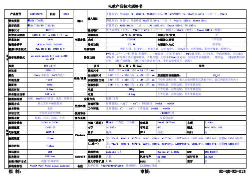
55E72RD-K 机芯9R28背光类型显示类型屏幕尺寸输出端口有效显示面积电源电压电源开关/位置屏幕比例功耗电源接入类型物理分辨率待机功耗电源接入方式视频/伴音制式亮度项目对比度整机尺寸颜色含挂架尺寸所适配的挂架编码:可视角度安装预留空间刷新率包装体积响应时间净重伴音输出功率毛重触摸面材质触摸方式存储环境技术特性工作环境书写方式使用寿命触摸点数操作系统触摸分辨率电脑(选配)■OPS □内置 □外挂处理器Intel I5-4460主频 3.2GHz 扫描速度内存4G DDR3芯片组H81硬盘500G HDD,SSD 光标速度显卡集成声卡集成WIFI有触摸精度响应时间通讯接口系统版本Android 4.4CPU Cortex A7 1.2GHz GPU IMG SGX544抗光能力处理器核数八核机身内存8G ROM 运行内存1G RAM 安装/维护方式最大存储扩展 1 TBWIFI有蓝牙有系统兼容性备注拟 制:审核:GD-QR-RD-013触摸兼容视频格式端口电源参数规格/重量使用环境WindowsAndroid rm,rmvb,mpeg1/2/4,avi,h.265,vp,AVS特色功能≤10ms ②:VGA*1,HDMI*1,WIFI*1,LAN*1,COM*1,MIC-IN*1,LINE-OUT*1,USB2.0*4,USB3.0*2(前置PC USB3.0变2.0)USB 80K Lux 内置/后维护式WinXP,Win7,Win8,Linux,Android配屏信息:7618-T5500C-A000;触摸模组:富创通6点模组电脑面板接口(二选一)标配:六点;选配:十点双系统运行32768 x 32768120帧/秒125P/S≤2mm ①:VGA*1,HDMI*1,WIFI*1,LAN*1,COM*1,MIC-IN*1,LINE-OUT*1,USB2.0*5,USB3.0*1(前置PC USB3.0有效)嵌入式红外触摸技术存储温度:-20℃ ~ 60℃;存储湿度:10%RH ~ 90%RH 无驱工作温度:0℃ ~ 50℃;工作湿度:10%RH ~ 90%RH手指及非透明物体≥60000小时10W x 245.6kg不含电脑;挂架选配,另外单独包装标配:3mm钢化白玻璃;选配:防眩光安装方式壁挂/支架60Hz 1467(长)x 935(高)x 242(厚)mm纸箱包装;挂架选配,另外单独包装6.5ms 39Kg 不含电脑;挂架选配,另外单独包装8bit.真彩色(1670万色)1287(长)x 805(高)x 130(厚)mm GD_18≈180°1317(宽)x 835(高)x 160(深)mm 当使用适配挂架,嵌入安装到推拉式黑板中时,建议预留的空间尺寸330 cd/㎡长 x 高 x 厚(mm)备注4000:11287(长)x 805(高)x 89(厚)mm 1920 x 1080(1080P)≤0.5W品字尾PAL DK/I/BG NTSC M/N 电视功能我的应用,影视中心,电视节目,云游戏中心,资讯浏览,应用商城,影视全搜索,购物中心55英寸数字音频*1(下置),VGA伴音/AV*1(二合一)(侧置),VGA*1(侧置),Touch USB*1(侧置)1209.6(H) x 680.4(V)mm110-240V/50-60Hz无16:9约150W 三芯电源电教产品技术规格书产品型号下置端子:网络端口*1,HDMI*2,RS232串口*1,RF(ATV+DTV)*1,VGA伴音/AV*1(二合一),VGA*1■LED □CCFL 侧置端子:分量*1,分量伴音/VGA伴音/AV*1(三合一),VGA*1,USB*2,Micro SD*1■2D □3D/PR □3D/SG前置端子:HDMI/MHL*1(二合一),PC USB3.0*1,Touch USB*1,TV USB*1显示输入端口TV按键三合一(开机/待机/单独听),一键黑屏(节能/单独听),PC按键前置,上拉菜单,全通道触摸、书写批注和保存,信号源自动识别和切换,手势识别,支持手机Wifi麦克风,支持蓝牙音箱播放,一键加速,一键触摸禁用和开启,白板手势板擦,白板书写自动调节亮度,实时温湿度显示(选配)。
触摸屏规格书21.5寸
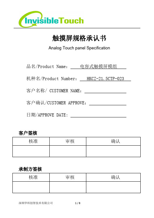
触摸屏规格承认书Analog Touch panel Specification品名/Product Name:电容式触摸屏模组机种名/Product Number: HKCZ-21.5CTP-023 客户名称/ CUSTOMER NAME:客户确认/CUSTOMER APPROVE:日期/APPROVE DATE: 客户签核承制方签核目录目录 (2)适用范围 (3)变更记录 (3)1.产品规格 (5)1.1 产品尺寸 (5)1.2 产品结构 (5)1.3 产品参数 (5)1.4 产品功耗 (6)1.5 产品使用、保存环境 (6)2.可靠性标准规范 (6)3.结构图纸 (7)6.注意事项 (8)适用范围本规格书为明确规范本公司产品触控面板性能而订定,当本规格书与其它个别规格书内容有抵触情况发生时,仍以本规格书标准为最优先。
本规格书内容如有项目不足或内容需变更时,须经由会议讨论后另订之。
This specification defines performance of input surfaces for our transparent analog touch panels. In the event of a conflict between this specification and applicable individual specification, this specification takes precedence. Items missing from this specification are to be decided subject to discussion.变更记录1.产品规格1.1 产品尺寸1.2 产品结构1.3 产品参数1.4 产品功耗1.5 产品使用、保存环境2.可靠性标准规范3.结构图纸6.注意事项1.汗水或油脂等若附着于纳米银线层上,将会影响纳米银线层表面阻抗质特性,故勿在未戴手套下直接触摸表面。
h系列触摸一体机规格书
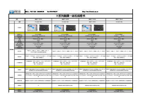
前置感应器
遥控接收*1,PC状态*1,TV状态*1,黑板阻挡感应*1,光线强度感应*1 遥控接收*1,PC状态*1,TV状态*1,黑板阻挡感应*1,光线强度感应*1 遥控接收*1,PC状态*1,TV状态*1,黑板阻挡感应*1,光线强度感应*1 遥控接收*1,PC状态*1,TV状态*1,黑板阻挡感应*1,光线强度感应*1
Windows,Linux,Android,MAC 支持自带软件检测功能,可测试设备好坏. 支持远程对触摸硬件控制程序(MCU)升级功能.
前置嵌入式(可前维护) HID免驱
4MM物理钢化玻璃(可选防眩光) 手指,书写笔,带手套的手或其他非透明触摸感应介质
4096X4096 USB 2.0 ≥120Hz
≤160W ≤0.5W 50000小时 100-240V, 50/60Hz
有 选配 选配 1296X730X81mm 55Kg 1425x210x950mm 70Kg
MINI ATX 模块
H61 CPU:G2010、i3、i5、i7
2G/4G 500G Windows7操作系统 集成 集成 选配 HDMI,USB,VGA,音频,RJ-45网络接口
2X10W
TV接口*1,AV输入*1,YPbPr*1,多媒体(USB)*2,HDMI*3 TV接口*1,AV输入*1,YPbPr*1,多媒体(USB)*2,HDMI*3 TV接口*1,AV输入*1,YPbPr*1,多媒体(USB)*2,HDMI*3
输出端口
AV输出*1,VGA 输出*1,AUDIO(3.5mm耳机)*1,USB*1(触摸 AV输出*1,VGA 输出*1,AUDIO(3.5mm耳机)*1,USB*1(触摸 AV输出*1,VGA 输出*1,AUDIO(3.5mm耳机)*1,USB*1(触摸 AV输出*1,VGA 输出*1,AUDIO(3.5mm耳机)*1,USB*1(触摸
Philips BDT5571VX 55英寸LCD触摸屏 multimedia 显示屏说明书
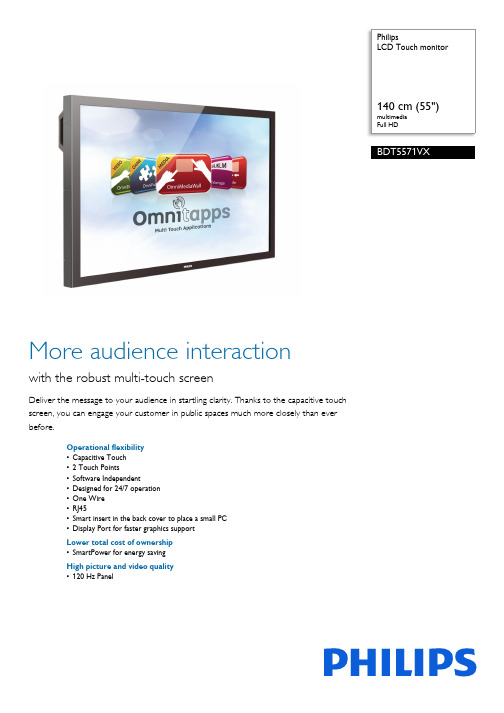
PhilipsLCD Touch monitormultimediaFull HDBDT5571VXMore audience interactionwith the robust multi-touch screenDeliver the message to your audience in startling clarity. Thanks to the capacitive touchscreen, you can engage your customer in public spaces much more closely than everbefore.Operational flexibility•Capacitive Touch•2Touch Points•Software Independent•Designed for 24/7 operation•One Wire•RJ45•Smart insert in the back cover to place a small PC•Display Port for faster graphics supportLower total cost of ownership•SmartPower for energy savingHigh picture and video quality•120 Hz PanelHighlights120 Hz PanelEnjoy stunningly clear video images thanks to the 120 Hz panel. Even fast moving action scenes can be seen without being blurred, which will enhance your viewing experience.2 Touch PointsEnjoy the interactivity of multi-touch functionality. It has the advantages of a more robust touch screen combined with the multi-touch gestures for using more versatile touch software.Capacitive TouchThis capacitive touch has 5-mm tempered glass. Therefore it is perfectly practical for public use and easy to clean.One WireTake full control of your display by running all operational commands, as well as your video signal, through just one single HDMI cable. Thisunique feature makes it so much easier andmore convenient to ensure the smoothrunning and maintenance of your display.Consumer Electronics Control (CEC)commands make finding out vital informationabout your display absolute child's play.RJ45Simple management of your display is availablethanks to the introduction of a LAN (RJ45)port. You can configure each display or findout the status of each device quickly andconveniently via an RJ45 connection.Smart insertProfessional PCs are part of most multi-userTouch Screen installations. Quite often theyadd additional depth to the public display and alot of cable clutter. This Multi-user TouchScreen contains a Smart insert in the backcover that will fit many professional compactPCs. In addition, it offers provisions forefficient cable management.SmartPowerThe backlight intensity can be controlled andpre-set by the system to reduce the powerconsumption by up to 50%, which savessubstantially on energy costs.Software IndependentOur touch screens are software independentand work with most touch-screen softwarecommercially available, including Windows XP/7 and Mac OS, Omnitapps – BMT1909/00.Connect via USB to a PC or laptop.Issue date 2022-05-18 Version: 1.0.112 NC: 8670 000 93371 EAN: 87 12581 65496 2© 2022 Koninklijke Philips N.V.All Rights reserved.Specifications are subject to change without notice. Trademarks are the property of Koninklijke Philips N.V. or their respective owners.SpecificationsAccessories•Included accessories: Remote Control, Batteries for remote control, AC Power Cord, VGA cable, User manual on CD-ROM, Owner's Manual, Touch Screen Driver•Optional accessories: Fixed wall mount, Flexible wall mount, Ceiling mount, Electric StandBMT1851/00, Multi User Touch SW, Software Omnitapps BMT1909/00Connectivity•AV input: HDMI x 1, Component (YPbPr) x 1, Composite (RCA) x 1, Composite (BNC) x 1, S-video x 1, Audio (L/R) x 2•AV output: Optional DVI Out•Other connections: AC-out, Display Port, External loudspeaker connector•PC: VGA-in D-Sub 15HD, VGA-out D-Sub 15HD, DVI-D x 1, RS232 D-Sub9, RS232 D-sub9 output, 3.5 mm PC audio input x 1•Touch Screen: USBConvenience•Ease of installation: AC Out, Carrying Handles, Smart Insert•Energy-saving functions: Ambient light sensor, Smart Power•Keyboard control: Hidden, Lockable •Network controllable: RJ45, RS232•Picture in picture: PBP, PIP, POP•Picture performance: Advanced colour control •Placement: Portrait, Landscape•Remote control signal: Lockable•Safety control functions: Heat Control, Temperature Sensor•Screen-saving functions: Pixel shift, Low brightness Dimensions•Bezel thickness: 36.6 mm horizontal, 36.3 mm vertical•Product weight: 62 kg•Set dimensions (W x H x D): 1293 x 759 x 142.8 mm•Smart Insert mount: 300 x 320 x 64 mm •VESA Mount: 400 x 400 mm (Set). 100 x 100 mm (Smart insert)Miscellaneous•Bezel: black, RAL 9005F13•On-Screen Display Languages: English, French, German, Italian, Polish, Turkish, Russian, Simplified Chinese•Regulatory approvals: CCC, CE, FCC, Class B, RoHS, UL/cUL•Warranty: Europe 3 yearsOperating conditions•MTBF: 60.000 hour(s)•Relative humidity: 10-90 %•Temperature range (operation): 0 - 40 °C Packaging Data•Net weight: 35•Number of products included: 1•Packaging dimensions (W x H x D):: 1339 x 940 x 305 mm•Tare weight: 8.5 kgPicture/Display•Aspect ratio: 16:9•Brightness: 700 cd/m²•Contrast ratio (typical): 1300:1•Diagonal screen size: 55 inch / 140 cm •Display colours: 1.06 Billion colours•Display technology: 120 Hz Panel•Optimum resolution: 1920 x 1080 @ 60 Hz •Panel resolution: 1920 x 1080p•Response time (typical): 10 ms•Viewing angle: 178º (H)/178º (V)Power•Consumption(On mode): Typical 214 W •Mains power: 90-264 VAC, 50/60 Hz •Standby power consumption: <1 W (Easylink and RS232 active)Sound•Built-in speakers: 2 x 12 W (8 Ohm) Supported Display Resolution •Computer formatsResolution Refresh rate640 x 480 60, 67, 72, 75 Hz800 x 600 56, 60, 72, 75 Hz1024 x 768 60 Hz1280 x 768 60 Hz1280 x 800 60 Hz1280 x 1024 60 Hz1360 x 768 60 Hz1366 x 768 60 Hz1440 x 900 60 Hz1600 x 1200 60 Hz1920 x 1080 60 Hz1920 x 1200 60 Hz•Video formatsResolution Refresh rate480i 60 Hz480p 60 Hz576i 50 Hz576p 50 Hz720p 50, 60 Hz1080i 50, 60 Hz1080p 50, 60 HzInteractivity•Multi-touch technology: 2 Touch Points simultaneously, Capacitive touch, USB connection, 5-mm safety glass。
Unitronics 1 Samba PLC+HMI 3.5寸、4.3寸、7寸触摸屏技术规范说明书

Samba™PLC+HMI SM35-J-RA22SM43-J-RA22SM70-J-RA22Technical SpecificationsOrdering InformationItemSM35-J-RA22 PLC with Flat panel, Color touch display 3.5’’SM43-J-RA22 PLC with Flat panel, Color touch display 4.3’’SM70-J-RA22 PLC with Flat panel, Color touch display 7’’You can find additional information, such as wiring diagrams, in the product’s installation guide located in the Technical Library at .Power SupplyItem SM35-J-RA22 SM43-J-RA22 SM70-J-RA22Input voltage 24VDCPermissible range 20.4VDC to 28.8VDC with less than 10% rippleMax. currentconsumptionSee Note 1npn inputs 275mA@24VDC 275mA@24VDC 330mA@24VDCpnp inputs 235mA@24VDC 235mA@24VDC 295mA@24VDCNotes:1. To calculate the actual power consumption, subtract the current for each unused element from the maximumSM35/SM43SM70*If the analog outputs are not configured, then subtract the higher value.Digital InputsNumber of inputs 12. See Note 2Input type See Note 2Galvanic isolation NoneNominal input voltage 24VDCInput voltagepnp (source) 0-5VDC for Logic ‘0’17-28.8VDC for Logic ‘1’npn (sink) 17-28.8VDC for Logic ‘0’0-5VDC for Logic ‘1’Input current 3.7mA@24VDCInput impedance 6.5KΩResponse time 10ms typical, when used as normal digital inputsInput cable lengthNormal digital input Up to 100 metersHigh Speed Input Up to 50 meters, shielded, see Frequency table below12/16 Samba™PLC+HMI2High speed inputs Specifications below apply when wired as HSC/shaft-encoder. See Note 2Resolution 32-bitNotes:2. This model comprises a total of 12 inputs.All 12 inputs may be used as digital inputs. They may be wired in a group via a single jumper as either npn or pnp.In addition, according to jumper settings and appropriate wiring:- Inputs 5 and 6 can function as either digital or analog inputs.- Input 0 can function as a high-speed counter, as part of a shaft-encoder, or as normal digital inputs.- Input 1 can function as either counter reset, normal digital input, or as part of a shaft-encoder. - If input 0 is set as a high-speed counter (without reset), input 1 can function as a normal digital input.- Inputs 7-8 and 9-10 can function as digital, thermocouple, or PT100 inputs; input 11 can also serve as the CM signal for PT100. 3. pnp/npn maximum frequency is at 24VDC. Analog Inputs Number of inputs 2, according to wiring as described above in Note 2 Input type Input rangeInput impedanceMaximum input ratingGalvanic isolation NoneConversion method Voltage to frequency Normal modeResolution, except 4-20mA 14-bit (16384units)Resolution, at 4-20mA 3277 to 16383 (13107 units)Conversion time 100ms minimum per channel. See Note 4. Fast modeResolution, except 4-20mA 12-bit (4096 units)Resolution, at 4-20mA 819 to 4095 (3277 units)Conversion time 30ms minimum per channel. See Note 4. Accuracy±0.44%Status indicationYes. See Note 5Notes:4. Conversion times are accumulative and depend on the total number of analog inputs configured.For example, if only one analog input (fast mode) is configured, the conversion time will be 30ms; however, if two analog (normal mode) and two RTD inputs are configured, the conversion time will be 100ms + 100ms + 300ms + 300ms = 800ms. 5.SMxx-J-RA22 Technical Specifications 2/163RTD Inputs RTD TypePT100Temperature coefficient α 0.00385/0.00392Input range -200 to 600︒C/-328 to 1100︒F. 1 to 320Ω. IsolationNoneConversion method Voltage to frequencyResolution0.1︒C/0.1︒FConversion time 300ms minimum per channel. See Note 4 above Input impedance >10MΩ Auxillary current for PT100 150μA typical Accuracy ±0.44% Status indication Yes. See Note 6 Cable length Up to 50 meters, shielded Notes:Input range See Note 7 IsolationNoneConversion method Voltage to frequencyResolution0.1︒C/ 0.1︒F maximumConversion time 100ms minimum per channel. See Note 7 above Input impedance>10MΩCold junction compensationLocal, automatic Cold junction compensation error ±1.5︒C/±2.7︒F maximum Absolute maximum rating ±0.6VDC Accuracy±0.44%Warm-up time ½ hour typically, ±1︒C/±1.8︒F repeatability Status indicationYes. See Note 6 aboveNotes:7. The device can also measure voltage within the range of -5 to 56mV, at a resolution of 0.01mV.The device can also measure raw value frequency at a resolution of 14-bits (16384). Input ranges are shown2/16Samba™PLC+HMI4 Digital OutputsNumber of outputs 8 relay (in 2 groups). See Note 8 Output type SPST-NO (Form A) Isolation By relay Type of relay Tyco PCN-124D3MHZ or compatible Output current (resistive load) 3A maximum per output 8A maximum total per common Rated voltage 250VAC / 30VDC Minimum load 1mA, 5VDC Life expectancy 100k operations at maximum load Response time 10ms (typical) Contact protection External precautions required (see Increasing Contact Life Span in theproduct’s I nstallation Guide)Notes:8. Outputs 0, 1, 2 and 3 share a common signal. Outputs 4, 5, 6, and 7 share a common signal.Analog OutputsNumber of outputs 2Output range 0-10V, 4-20mA. See Note 9 Resolution12-bit (4096 units)Conversion time Both outputs are updated per scan Load impedance1kΩ minimum—voltage 500Ω maximum—currentGalvanic isolation None Accuracy ±0.3% Notes:9. Note that the range of each I/O is defined by wiring, jumper settings, and within the controller’s software.Graphic Display ScreenItemSM35-J-RA22 SM43-J-RA22SM70-J-RA22LCD TypeTFT, LCD display TFT, LCD display TFT, LCD display Illumination backlight White LED White LED White LED Display resolution 320x240 pixels 480x272 pixels 800x480 pixels Viewing area 3.5" 4.3" 7" Colors65,536 (16-bit) 65,536 (16-bit) 65,536 (16-bit) TouchscreenResistive, analog Resistive, analog Resistive, analog Screen brightness control Via software (Store value to SI 9, values range: 0 to 100%) Virtual KeypadDisplays virtual keyboard when the application requires data entry.SMxx-J-RA22 Technical Specifications 2/16 ProgramItem SM35-J-RA22 SM43-J-RA22 SM70-J-RA22Memory sizeApplication Logic 112KB 112KB 112KBImages 1MB 2MB 5MBData Tables 32K dynamic data (recipe parameters, datalogs, etc.)16K fixed data (read-only data, ingredient names, etc)HMI displays Up to 24Program scan time 15µs per 1kb of typical applicationCommunication PortsPort 1 1 channel, RS232 (SM35) , USB device (SM43/SM70)Galvanic isolation SM35 and SM43 – NoSM70 - YesBaud rate 300 to 115200 bpsRS232 (SM35 only)Input voltage ±20VDC absolute maximumCable length 15m ma ximum (50’)USB device (SM43,SM70 only)Port type Mini-BSpecification USB 2.0 complaint; full speedCable USB 2.0 complaint; up to 3mPort 2 (optional) See Note 10CANbus (optional) See Note 10Notes:10. The user may order and install one or both of the following modules:- A serial RS232/RS485 isolated/non-isolated interface module, or an Ethernet Interface module in port 2.- A CANbus modulemodules documentation is available on the Unitronics website.MiscellaneousClock (RTC) Real-time clock functions (date and time)Battery back-up 7 years typical at 25°C, battery back-up for RTC and system data, includingvariable dataBattery replacement Yes. Coin-type 3V, lithium battery, CR245052/16Samba™PLC+HMI6 DimensionsItem SM35-J-RA22 SM43-J-RA22 SM70-J-RA22 Size109 x 114.1 x 68mm (4.29 x 4.49 x 2.67”). See Note 11 136 x 105.1 x 61.3mm (5.35 x 4.13 x 2.41”). See Note 11 210 x 146.4 x 42.3mm (8.26 x 5.76 x 1.66”). See Note 11 Weight226g (7.97 oz)365g (12.87 oz)654g (23.07 oz)Notes:11. For exact dimensions, refer to t he product’s Installation Guide .EnvironmentOperational temperature 0 to 50ºC (32 to 122ºF) Storage temperature -20 to 60ºC (-4 to 140ºF)Relative Humidity (RH) 10% to 95% (non-condensing)Mounting method Panel mounted (IP65/66/NEMA4X) DIN-rail mounted (IP20/NEMA1) Operating Altitude 2000m (6562 ft)Shock IEC 60068-2-27, 15G, 11ms durationVibrationIEC 60068-2-6, 5Hz to 8.4Hz, 3.5mm constant amplitude, 8.4Hz to 150Hz, 1G acceleration.02/16。
Control4 7寸移动式触摸屏产品说明书

在 Composer 软件中将 Control4 7 英寸移动式触摸屏添加进项目: 1. 打开 Composer 并连接至本地 Director。 2. 将触摸屏图标拉至项目设备列表中。
a 在 System Design 界面左栏的项目结构图上,点中该触摸屏所在的房间名。 b 在 My Drivers 中,双击 Touch Screen-7” Portable。 3. 辨识该设备。 a 进入 Connections 选项,点击 Network。 b 在 IP Network Connections 列表中,点中 Touch Screen-7” Portable,并点击 Identify。 c 按弹出对话框中的指示在触摸屏上操作,使其被辨识进网络。 d 当网络地址显示于 Composer 上时,点击 Close。
7 寸移动式触摸屏产品说明书
型号 C4-TSM7-G-B
规格
面板 7 英寸 XGA 彩色液晶屏 分辨率:800×480 亮度:230 cd/m2 对比度:500:1
无线 基于 IEEE802.11b/g 无线局域网协议 内置天线
尺寸 9.5×5×4(长宽高,单位英寸) 网络 WiFi 无线节点须已与 Control4 控制主机相通信
连接情况。 5. 请核实日期、默认房间名、时间等显示于屏幕顶端的信息,以确保所有连接项目均已建
立。
DHCP。如果您需用静态 IP,请为此设备预先分配一个 IP 地址。 3. 在触摸屏上,选择 Info->Network->Wireless Settings 4. 在 Wireless Settings 选项中按如下步骤进行操作:
a 按下 Add b 点击输入框,弹出 SSID 输入框。输入 SSID 值(大小写敏感),点击 Done。 c 如果已启用 WEP/WPA,按下 WEP/WPA 按钮,选择对话框,使用弹出的的键盘输入 WEP/WPA 密码长度;若有要求,请输入密码值,并点击 Done。 d 请输入无线网络设置参数以使触摸屏能与网络连接。在连接上无线网络后,按下 OK 键返回无线网络设置页面。 e 再次按下 OK 键以返回网络设置页面。更新后的参数将显示于此页面。 5. IP 地址的默认设置为 DHCP。如果您需要设置静态 IP 地址,请按如下步骤进行设置: a 在网络设置界面中点击 IP 地址输入栏。 b 选择 Assigned 选项。 c 在输入框中输入 IP 地址。 d 按下 OK 键返回网络设置界面。 现在您可以通过该触摸屏来与 Control4 Director 进行通信了。
环保设备触摸屏57寸说明书(doc 23页)
环保设备触摸屏57寸说明书(doc 23页)目录产品介绍产品的型号和名称---------------------------------------------------------------------------------------------1产品用途、适用范围及特点-------------------------------------------------------------------------------1主要技术性能和技术参产品使用条件--------------------------------------------------------------------------------------------------2主要技术参数----------------------------------------------------------------------------------------------------3产品的功能和特点---------------------------------------------------------------------------------------------3主要结构和工作原理产品结构-----------------------------------------------------------------------------------------------------------5主回路工作原理-----------------------------------------------------------------------------------------------5安装与使用设备的验收试验-----------------------------------------------------------------------------------------------6设备的安装------------------------------------------------------------------------------------------------------6设备的使用------------------------------------------------------------------------------------------------------7设备的维护、保养--------------------------------------------------------------------------------------------------12产品的成套性和备件-----------------------------------------------------------------------------------------------12附录---------------------------------------------------------------------------------------------------------------------------13▲化学工业:用于回收烟气中有价值的成份,在制酸工业中用于除雾、除尘等。
郎汉德PLC触摸屏一体机(7寸)产品说明书
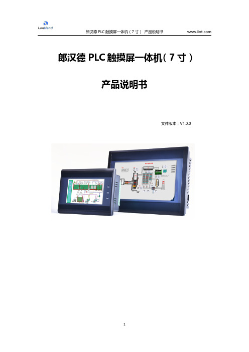
郎汉德PLC触摸屏一体机(7寸)产品说明书文件版本:V1.0.0目录1.产品简介 (3)2.参数详情 (3)2.1.电气参数 (3)2.2.PLC编程电缆参数 (4)2.3.选型表 (6)2.4.拨码状态 (7)2.5.接线图 (8)2.5.1.晶体管输出型号引脚定义 (8)2.5.2.继电器输出型号引脚定义 (10)2.6.PLC地址 (12)2.6.1.PLC地址使用情况 (12)2.6.2.特殊寄存器.和位 (13)2.7.模拟量转换 (17)2.8.兼容三菱指令 (17)3.通信使用 (22)3.1.串口通信配置 (22)3.2.一体机内部PLC与HMI通讯(COM2) (23)3.2.1.使用FX3U协议内部通讯 (23)3.2.2.使用Modbus RTU内部通讯 (26)3.3.串口通信发送与接收数据的应用(COM4) (28)3.3.1.PLC做为Modbus从站通信 (28)3.3.2.串口自由通信协议ADPRW指令使用 (29)3.3.3.Modbus主站通信协议ADPRW指令使用 (32)4.售后 (34)4.1.联系方式 (34)4.2.免责声明 (34)1.产品简介本产品为PLC触摸屏一体机。
PLC支持3U编程风格;HMI组态图库丰富。
2.参数详情2.1.电气参数类别项目参数电气环境供电电源额定24V,12-32V宽压输入范围;内部与外供电电气隔离工作温度0~55°C湿度5%-95%RH(非结露)抗干扰性峰值:1500vp-p;幅度1uS;上升时间:30ms;周期30-100HZ抗震动符合IEC61121-2标准电气隔离性能通讯隔离性通讯口均与内部隔离电源隔离性内部5V、15V之间隔离;与24V输入隔离数字量量输入导通状态高于DC15V,2.5mA 关断状态低于DC7V,1mA晶体管输出响应时间ON->OFF20us以内OFF->ON50us以内输出电压范围DC5V~30V额定输出负载0.75A@DC24V继电器输出响应时间10ms以内输出电压范围DC5V-30或AC5V~250V 额定输出电压DC24V/2A或AC220V/2.0A 使用寿命机械1千万次电气10万次(额定负载)模拟量输出输出范围电压输出0~10V 电流输出0~20mA模拟量输入输入范围电流输入0-20mA或4-20mA电压输入0-10V运动控制脉冲输出速度可达200KHZ 计数输入速度可200K以上2.2.PLC编程电缆参数一体机的PLC部分,对应的编程口为RS232通信。
7 寸 TFT显示屏规格书
CUSTOMER APPROVAL SHEETCompany NameMODELA070FW03 VDCUSTOMERAPPROVEDTitle : Name :□ APPROVAL FOR SPECIFICATIONS ONLY (Spec. Ver. )□ APPROVAL FOR SPECIFICATIONS AND ES SAMPLE (Spec. Ver. ) □ APPROVAL FOR SPECIFICATIONS AND CS SAMPLE (Spec. Ver. ) □CUSTOMER REMARK :AUO PM : Orion PengP/N : 97.07A04.D00Comment :1 Li-Hsin Rd. 2. Science-Based Industrial ParkHsinchu 300, Taiwan, R.O.C.Tel: +886-3-500-8899 Fax: +886-3-577-2730Doc. version : 0.0 Total pages : 28A UOCo n fi de n ti a lF or Pr om a t eI nt er na l Us eOn l y / 2010/1/5Product Specification7.0" COLOR TFT-LCD MODULEModel Name :A070FW03 VDPlanned Lifetime: From 2009/Dec To2011/DecPhase-out Control:From 2011/Jul To 2011/DecEOL Schedule:2011/Jul< >Preliminary Specification < >Final SpecificationNote: The content of this specification is subject to change.© 2009 AU Optronics All Rights Reserved, Do Not Copy.A UOCo n fi de n ti a lF or Pr om a t eI nt er na l Us eOn l y / 2010/1/5Page:1/28Record of RevisionVersion Revise Date Page Content0.0 2009/03/10All First DraftA UOCo n fi de n ti a lF or Pr om a t eI nt er na l Us eOn l y / 2010/1/5Page:2/28ContentsA. General Information.....................................................................................................................................3B.Outline Dimension (4)1. TFT-LCD Module – Front View....................................................................................................................42. TFT-LCD Module – Rear View....................................................................................................................5 C.Electrical Specifications .............................................................................................................................6 1. TFT LCD Panel Pin Assignment .................................................................................................................6 2. Backlight Pin Assignment............................................................................................................................7 3. Absolute Maximum Ratings.........................................................................................................................7 3. Electrical DC Characteristics.......................................................................................................................8 4. Electrical AC Characteristics.....................................................................................................................10 6. Power On/Off Characteristics....................................................................................................................17 D. Optical Specification .................................................................................................................................18 E. Reliability Test Items .................................................................................................................................21 F.Packing and Marking.................................................................................................................................24 1. Packing Form............................................................................................................................................24 2. Module/Panel Label Information ...............................................................................................................25 3. Carton Label Information...........................................................................................................................25 G.Precautions (26)A UOCo n fi de n ti a lF or Pr om a t eI nt er na l Us eOn l y / 2010/1/5Page:3/28A. General InformationThis product is for portable DVD and digital photo frame application. NO. ItemUnit Specification Remark1 Screen Sizeinch 7.0(Diagonal)2 Display Resolution dot480RGB(W)×234(H)3 Overall Dimensionmm 164.9 (W)×100(H)×5.7(D) Note 1 4 Active Area mm154.08(W)×86.58(H) 5 Pixel Pitchmm 0.107(W)×0.370(H)6 Color Configuration --R. G. B. Stripe Note 2 7 NTSC Ratio% 48%8 Display Mode -- Normally White 9Panel surface Treatment -- Anti-Glare, 3H10 Weight g TBD 11 LCD Module Power ConsumptionW 2.212 Viewing direction6 o’clock (gray inversion)Note 1: Not include blacklight cable and FPC. Refer next page to get further information. Note 2: Below figure shows dot stripe arrangement.( 1………………………..234)A UOCo n fi de n ti a lF or Pr om aPage:4/28ALL RIGHTS STRICTLY RESERVED. ANY PORTION OF THIS PAPER SHALL NOT BE REPRODUCED, COPIED, OR TRANSFORMED TO ANY OTHER FORMSWITHOUT PERMISSION FROM AU OPTRONICS CORP.B. Outline Dimension (D00)1. TFT-LCD Module – Front ViewA UOPage:5/28ALL RIGHTS STRICTLY RESERVED. ANY PORTION OF THIS PAPER SHALL NOT BE REPRODUCED, COPIED, OR TRANSFORMED TO ANY OTHER FORMSWITHOUT PERMISSION FROM AU OPTRONICS CORP.2. TFT-LCD Module – Rear ViewA UPage:6/28C. Electrical Specifications1. TFT LCD Panel Pin AssignmentPin no Symbol I/O DescriptionRemark1 GND - Ground for logic circuit2 V CC I Supply voltage of logic control circuit for scan driver3 V GL I Negative power for scan driver4 V GH IPositive power for scan driver5 STVR I/O Vertical start pulse Note 16 STVL I/O Vertical start pulse Note 17 CKV I Shift clock input for scan driver 8 U/D I UP/DOWN scan control input Note 1,29 OEV I Output enable input for scan driver 10 VCOM I Common electrode driving signal 11 VCOM I Common electrode driving signal12 L/R I LEFT/RIGHT scan control input Note 1,213 MOD I Sequential sampling and simultaneous sampling setting14 OEH IOutput enable input for data driver15 STHL I/O Start pulse for horizontal scan lineNote 1 16 STHR I/O Start pulse for horizontal scan lineNote 1 17 CPH3 I Sampling and shifting clock pulse for data driver18 CPH2 I Sampling and shifting clock pulse for data driver19 CPH1 I Sampling and shifting clock pulse for data driver20 V CC I Supply voltage of logic control circuit for data driver21 GND - Ground for logic circuit22 VRIAlternated video signal input(Red) 23 VGI Alternated video signal input(Green) 24VBI Alternated video signal input(Blue)25 AV DD I Supply voltage for analog circuit 26AV SS-Ground for analog circuitA UOCo n fi de n ti a lF or Pr om a t eI nt er na l Us eOn l y / 2010/1/5Page:7/28I: Input pin; P: Power pin; G: Ground pin; C: capacitor pinRefer to figure as below:Pin26 Pin12. Backlight Pin AssignmentRecommended connector : E&T H201K-P020N-02BPin no Symbol I/O Description Remark1 VLEDPLED power supply2GNDLEDP LED ground3. Absolute Maximum RatingsItemSymbol Condition Min. Max. Unit RemarkV CCGND=0-0.3 7 V AV DD AGND=0-0.3 7VV GH -0.3 18 V V GL GND=0-15 0.3 V Power voltageV GH -V GL-33VV i-0.3 AV DD +0.3 VNote 3 V I-0.3 V CC +0.3 V Note 4 Input signal voltageVCOM-2.9 7.5 VNote 1: Functional operation should be restricted under ambient temperature (25℃).Note 2: Maximum ratings are those values beyond which damages to the device may occur. Functionaloperation should be restricted to the limits in the Electrical Characteristics chapter.Note 3: VR, VG, VB.Note 4: STHL, STHR, OEH, LRC, CPH1~CPH3, STVD, STVU, OEV, CKV, UDC, MODA UOCo n fi de n ti a lF or Pr om a t eI nt er na l Us eOn l y / 2010/1/5Page:8/283. Electrical DC Characteristicsa. Typical Operation Condition (AGND =GND = 0V)ItemSymbol Min. Typ. Max. Unit Remark V CC3 3.3 5.5 VDigital powerAV DD4.5 55.5 V Analog PowerV GH 14.3 15 15.7 V Positive power supply for gate driver Power VoltageVGL-10.5 -10 -9.5 V Negative power supply for gate driverV iA 0.4 - AV DD -0.4V Refer to Horizontal timing V iAC - 4- V AC component Video signal amplitude(VR,VG,VB) V iDC -AV DD /2 -VDC componentH LevelVIH 0.8xVCC - VCC VInputSignal Voltage L Level VIL GND - 0.2xVC VNote 1. V CAC 3.5 5.6 6.5 VAC component Gamma referencevoltageV CDC1.41.72.0VDC component Note 1: STHL, STHR, OEH, LRC, CPH1~CPH3, STVD, STVU, OEV, CKV, UDC, MOD.Note2: Must follow power On/Off Sequence.Note 3: If input signal amplitude is 3.3V, recommend value for Vcc is 3.3VIf input signal amplitude is 5V, recommend value for Vcc is 5Vb. Current Consumption (AGND=GND=0V)ParameterSymbol ConditionMin. Typ. Max. Unit RemarkInput current for V GH I GH V GH =15V- 0.12 1.0 m A Input current for V Gl I GL V Gl =-10V- 0.15 1.0 mA Input current for Vcc I CC DV CC =3.3- 2 6.0 mA Input current for Avdd I DDAV DD =5V-5.330mAA UOCo n fi de n ti a lF or Pr om a t eI nt er na l Us eOn l y / 2010/1/5Page:9/28c. Backlight Driving ConditionsThe backlight (LED module, Note 1) is suggested to drive by constant current with typical value.ParameterSymbol Min. Typ. Max. Unit Remark LED light bar CurrentI L-- 200 -- mABL Power ConsumptionP BL --2.1 --WNote 1 LED Life TimeL L 10,000 ---- Hr Note 2, 3Note 1: The LED driving condition is defined for LED module (24 LED). The voltage range will be 8.7 to 11.6V based on suggested driving current set as 200mA .Note 2: Define “LED Lifetime”: brightness is decreased to 50% of the initial value. LED Lifetime isrestricted under normal condition, ambient temperature = 25℃ and LED lightbar current =200mA .Note 3: If it uses larger LED lightbar voltage more than 200mA , it maybe decreases the LED lifetime.A UOCo n fi de n ti a lF or Pr om a t eI nt er na l Us eOn l y / 2Page:10/284. Electrical AC Characteristicsa. Signal AC CharacteristicsParameterSymbol Min. Typ. Max. Unit. Remark Clock cycle time t CPH100 103 107 ns CPH1 CPH pulse duty t CWH 405060%CPH1CPH pulse delay t C12 30 t CPH /3 t CPH /2 ns CPH1STH setup time t SUH 20 - - ns STHR,STHL STH hold time t HDH 20- - ns STHR,STHL STH pulse width t STH 1 t CPH STHR,STHL STH period t H 61.8 63.7 66.1 μs STHR,STHL OEH pulse width t OEH 1 - - t CPH OEH (Note 1)Sample and hold disable timet DIS1 1 - - t CPH Note 2 OEV pulse width t OEV 2.0 3.4 6.5 μs OEV CKV pulse width t CKV 1.0 3.1 4.68 μs CKV Clean enable timet DIS2 1.0- 1 t OEVμs Note 3 Horizontal display start t SH 1t CPH Horizontal display timing ranget DH 480t CPH STV setup time t SUV 400 -- ns STVU, STVD STV hold time t HDV 400 -- ns STVU, STVD STV pulse width t STV - -1t H STVU, STVDVertical display start t SV 3t H Vertical display timing ranget DV 234 t HVCOM rising time t rCOM - 5 μs VCOM falling time t fCOM- 5 μs VCOM delay time t DCOM 2 - - μs TFT charging time t ch 55 - - μs Output time delay t del 3 - - μs Setup time of analog VR/VG/VBt asu 60 - - ns Hold time of analog VR/VG/VBt ahd 40 - - ns Frame rate5060-HzNote 1: The maximum pulse width of OEH should refer to the minimum of tDIS1 and the hsyncback porch.Note 2: t DIS1 is time difference between OEH and STHL.Note 3: t DIS2 is time difference between OEV and CKVA UOCo n fi de n ti a lF or Pr om a t eI nt er na l Us eOn l y / 2010/1/5Sampling clock timingVersion:0.0Page: 15/28ALL RIGHTS STRICTLY RESERVED. ANY PORTION OF THIS PAPER SHALL NOT BE REPRODUCED, COPIED, OR TRANSFORMED TO ANY OTHER FORMS WITHOUT PERMISSION FROM AU OPTRONICS CORP.Vertical timing (From up to down)a lUs e On ly / 2010/1/5Version:0.0Page: 16/28ALL RIGHTS STRICTLY RESERVED. ANY PORTION OF THIS PAPER SHALL NOT BE REPRODUCED, COPIED, OR TRANSFORMED TO ANY OTHER FORMS WITHOUT PERMISSION FROM AU OPTRONICS CORP.Page: 17/28 6. Power On/Off CharacteristicsPower OnPage:18/28D. Optical SpecificationAll optical specification is measured under typical condition (Note 1, 2)Item Symbol Condition Min. Typ. Max. Unit Remark Response TimeRise FallTr Tfθ=0°-- --12 1824 36ms ms Note 3 Contrast ratioCRAt optimizedviewing angle 300 400 -- Note 4TopBottom LeftViewing AngleRight 30 50 50 5040 65 65 65 -- -- -- -- deg. Note 5Brightness Y Lθ=0° 320 400 -- cd/m 2 Note 6 X θ=0° 0.25 0.30 0.35 ChromaticityWhiteY θ=0° 0.27 0.32 0.37 UniformityΔY L%7075 -- %Note 7Note 1: Ambient temperature =25℃, and LED lightbar current I L = 200 mA . To be measured in the dark room.Note 2: To be measured on the center area of panel with a viewing cone of 1° by Topcon luminance meterBM-5A, after 15 minutes operation.Note 3: Definition of response time:The output signals of photo detector are measured when the input signals are changed from“black” to “white”(falling time) and from “white” to “black”(rising time), respectively.The response time is defined as the time interval between the 10% and 90% of amplitudes.Refer to figure as below.A UOCo n fi de n ti a lF or Pr om 1/5Note 4.Definition of contrast ratio:Contrast ratio is calculated with the following formula.statusBlack"" at is LCD when output detector Photo statusWhite"" at is LCD when output detector Photo (CR) ratio Contrast =Note 5. Definition of viewing angle, θ, Refer to figure as below.Note 6. Measured at the center area of the panel when all the input terminals of LCD panel areelectrically opened.Note 7: Luminance Uniformity of these 9 points is defined as below:A UOCo n fi de n ti a lF or Pr om a t eI nt er nA UOCo n fi de n ti a lF or Pr om a t eI nt er na l Us eOn l y / 2010/1/5Page:21/28E. Reliability Test ItemsNo. Test itemsConditions Remark1 High Temperature Storage240Hrs2 Low Temperature Storage Ta= -2240Hrs3 High Ttemperature Operation Tp240Hrs4 Low Temperature Operation Ta= -1 240Hrs5 High Temperature & High HumidityTp= 580% RH 240Hrs Operation6 Heat Shock -20d/1hr~70d/1hr judge 50cyclesNon-operation7 Electrostatic DischargeContact = ± 4 kV, class B Air = ± 8 kV, class BNote 4 8Image Sticking25, 4hrsNote 5Frequency range : 10~55HzStoke: 1.5mmSweep: 10 Hz ~55 Hz 2 hours for each direction of X,Y,Z9Vibration4 hours for Y directionNon-operationJIS C7021, A-10condition A : 15 minutes10 Mechanical Shock100G . 6ms, ±X,±Y,±Z3 times for each directionNon-operation JIS C7021,A-7condition C 11 Vibration (With Carton)Random vibration:0.015G 2/Hz from 5~200Hz–6dB/Octave from 200~500Hz IEC 68-3412 Drop (With Carton)Height: 60cm1 corner, 3 edges, 6 surfaces13 Pressure5kg, 5sec Note 6Note 1: Ta: Ambient Temperature. Tp: Panel Surface TemperatureNote 2: In the standard conditions, there is not display function NG issue occurred. All the cosmeticspecification is judged before the reliability stress.Note 3: All the cosmetic specification is judged before the reliability stress.Note 4 : All test techniques follow IEC6100-4-2 standard.A UOCo n fi de n ti a lF or Pr om a t eI nt er na l Us eOn l y / 2010/1/5Page:22/28Contact Discharge :330Ω, 150pF, 1sec, 8 point, 25times/pointgray pattern. After 20 minutes, the mura is less than JND 2.5Note 6: The panel is tested as figure. The jig is ψ10 mm made by Cu with rubber and the loadingspeed is 3mm/min on position 1~5. After the condition, no glass crack will be found and panelfunction check is OK.( no guarantee LC mura 、LC bubble)A UOCo n fi de n ti a lF or Pr om a t eI nt eUs eOn l y / 201Page:23/28A UOCo n fi de n ti a lF or Pr om a t eI nt er na l Us eOn l y / 2010/1/5Page:24/28F. Packing and Marking1. Packing FormA UOCo n fi de n ti a lF or Pn l y2. Module/Panel Label InformationThe module/panel (collectively called as the “Product”) will be attached with a label of Shipping Numberwhich represents the identification of the Product at a specific location. Refer to the Product outline drawing for detailed location and size of the label. The label is composed of a 22-digit serial number and printed with code128 with the following definition:Example:501M06ZL06123456781Z05: Product Manufacturing Week Code: WK50 Product Version: Version 1 Product Manufactuing Factory: M063. Carton Label InformationThe packing carton will be attached with a carton label where packing Q’ty, AUO Model Name, AUO PartNumber, Customer Part Number (Optional) and a series of Carton Number in 13 or 14 digits are printed. TheCarton Number is apparing in the following format:Refer to the drawing of packing format for the location and size of the carton label.A UOCo n fi de n ti a lF or Pr om a t eI nt er na l Us eOn l y / 2010/1/5G. Precautions1. Do not twist or bend the module and prevent the unsuitable external force for display module during assembly.2. Adopt measures for good heat radiation. Be sure to use the module with in the specified temperature.3. Avoid dust or oil mist during assembly.4. Follow the correct power sequence while operating. Do not apply the invalid signal, otherwise, it will cause improper shut down and damage the module.5. Less EMI: it will be more safety and less noise.6. Please operate module in suitable temperature. The response time & brightness will drift by different temperature.7. Avoid to display the fixed pattern (exclude the white pattern) in a long period, otherwise, it will cause image sticking.8. Be sure to turn off the power when connecting or disconnecting the circuit. 9. Polarizer scratches easily, please handle it carefully. 10. Display surface never likes dirt or stains.11. A dewdrop may lead to destruction. Please wipe off any moisture before using module.12. Sudden temperature changes cause condensation, and it will cause polarizer damaged.13. High temperature and humidity may degrade performance. Please do not expose the module to the direct sunlight and so on.14. Acetic acid or chlorine compounds are not friends with TFT display module.15. Static electricity will damage the module, please do not touch the module without any groundeddevice.16. Do not disassemble and reassemble the module by self.17. Be careful do not touch the rear side directly.18. No strong vibration or shock. It will cause module broken.19. Storage the modules in suitable environment with regular packing.20. Be careful of injury from a broken display module.21. Please avoid the pressure adding to the surface (front or rear side) of modules, because it will causethe display non-uniformity or other function issue.A UOCo n fi de n ti a lF or Pr om a t eI nt er na l Us eOn l y / 2010/1/5。
翰彩7寸屏规格书
2.1.2
Note (1) Permanent damage may occur to the LCD module if beyond this specification. Functional operation should be restricted to the conditions described under normal operating conditions. (2) Ta =25±2 (3) Test Condition: LED current 220 mA. The LED lifetime could be decreased if operating IL is larger than 220mA.
Interface pin connection
Electrical characteristics ……………………………. Reliability test items…………………………………… Outline dimension …………………………….……
Lot mark ……………………………………………... Package specification ………………………………. General precaution …………………………………….
The information contained in this document is the exclusive property of HannStar Display Corporation. It shall not be disclosed, distributed or reproduced in whole or in part without written permission of HannStar DisplaDi sp l a y C o rp .
触摸屏用户手册说明书
感谢您购买 COOLMAY MT 系列触摸屏。
本手册主要说明MT 系列触摸屏的产品特性、一般规格、硬件接口和软件设置方法等。
详细编程请参见《COOLMAY 触摸屏使用手册》。
触摸屏的主要特点:1、提供大量的矢量图库及支持自建图库2、高精度/高可靠性的电阻式触摸面板3、支持各种格式静态图片及GIF 动画4、支持windows 所提供的所有字体5、6万TFT 真彩显示器6、支持配方功能和数据存储、U 盘导出数据7、自带一个RS232和一个RS485通讯口8、基本版可竖屏显示9、可选装网口或音频10、基本版(基于WINCE 5.0系统)和升级版(基于WINCE 7.0系统)可选11、MT6037H /MT6050H (A )灰色/金色/银色面板可选,黑色/白色底壳可选 12、MT6037H /MT6050H (A )可墙体安装,可应用于智能家居/工业等领域产品信息1、 公司产品系列 MT 系列触摸屏2、 HMI 尺寸 6037:3.5寸 6043: 4.3寸 6050: 5寸 6070: 7寸 6100: 10寸3、 版本 H : 基本版 HV : 基本版竖屏;HA /HAS : 升级版 HAV /HAVS : 升级版竖屏4、 网口 W : 网口(选装)5、 音频 Y : 音频(选装)命名规则MT 123456070图1 安装尺寸图MT6100HAMT6043HMT6070H(A/AS)电气设计参考产品构造COM :PLC 与触摸屏 通讯上时快闪安装尺寸机械设计参考规格参数触摸屏用户手册表三:安装尺寸型 号安装尺寸外形尺寸W*H*D(mm)A(mm)B(mm)MT6050H(A)MT6070H(A/AS)MT6100HA13719426172138180146*88*25212*148*40275*194*36电源用端子台 USB 口PWR :通电指示灯触摸屏编程口液晶屏RS232/RS485网口(选装) ◆◆◆◆YW H--6143257图2 产品构造※ 更多规格批量客户可定制MT6043H(A)MT6070H(A/AS)MT6100HAMT6037H背面图MT6050H背面图型号MT6037H 3.5"TFT 液晶屏 4.3"TFT 液晶屏7.0"TFT 液晶屏10.2"TFT 液晶屏MT6043H(A)MT6070H(A/AS)MT6100HA 320*240480*272800*480/1024*6001024*60088*88*25mm 134*102*30mm 212*148*40mm 275*194*36mm 72*72mm 119*93mm 194*138mm 261*180mm 73*56mm 97*56mm 154*87mm 222*133mm 300cd/m²300cd/m²300cd/m²300cd/m²LED LED LED LED 128MB Flash ROM 65536真彩4线电阻屏100mA/24V150mA/24V200mA/24V280mA/24VCOM1: RS232 COM2: RS485400:1H 系列: ARM9内核 640MHz HA(S)系列: Cortex A8 720MHz-1GHz20ms 以内有电源失效检测12-24VDC ±10%<150mA @24VDC 符合EN50081-2和EN50082-2标准符合FCC Class A电压1500Vp -p ,脉冲周期1μs ,持续1s 10-25Hz (X 、Y 、Z 方向2G 30分钟)超过10M Ω@500VDC工程塑料ABS +PC 500VAC 1分钟IP65(前面板)0~50℃20~90%RH -20~70℃显示屏分辨率外形尺寸安装开孔尺寸显示尺寸亮度背光类型存储器颜色触摸面板功耗通讯端口对比度CPU 容许掉电USB??系统诊断供电电源认证FCC 兼容性抗干扰测试防震测试绝缘电阻外壳材料耐压测试防护等级工作环境温度工作环境湿度存储温度65536真彩4线电阻屏65536真彩4线电阻屏65536真彩4线电阻屏0.3kg0.33kg0.54kg0.7kg重量MT6050H(A)5.0"TFT 液晶屏800*480146*88*25mm 137*72mm 108*65mm 300cd/m²LED 150mA/24V65536真彩4线电阻屏0.33kg128MB Flash ROM 128MB Flash ROM 128MB Flash ROM 128MB Flash ROMH 系列: 64MB HA(S)系列: 128M运行内存121264357643572264357673541234657侧面四个安装扣位孔888888MT6037H 727288*88*25MT6043H(A)11993134*102*30MT6037H硬件接口◆FG 0V 24V触摸屏232/485口触摸屏下载口USB口网口COM1/COM2MT6043H(A)/MT6043KH(A)/MT6050KH(A) COM口引脚定义管脚号信号描述23TXDRXD 发送接收5地线GNDRS232通讯口定义RS485通讯口定义16BA485-485+MT6043H(A)背光寿命60000小时60000小时60000小时60000小时60000小时以太网口可选装万年历输入电压有常规为DC24±10%VDC ,也可以特别做成DC12V /DC5V 电源输入墙体安装镶嵌安装墙体安装镶嵌安装MT6050H(A)型号MT6037H MT6043H(A)MT6070H(A/AS)MT6100HAMT6050H(A)自然风冷冷却方式接上表FG 0V 24V 触摸屏485口USB口触摸屏下载口触摸屏232/485口网口(选装)(同COM1中的485口)COM1/COM2MT6070H(A/AS ) COM口引脚定义管脚号信号描述23TXDRXD 发送接收5地线GNDCOM1 RS232通讯口定义COM1/COM2 RS485通讯口定义16BA 485-485+MT6070H(A/AS)FG 0V 24V USB口触摸屏下载口网口(选装)触摸屏232/485口COM1MT6100HACOM口引脚定义管脚号信号描述23TXDRXD 发送接收5地线GNDRS232通讯口定义RS485通讯口定义16BA 485-485+MT6100HA* 编程软件触摸屏:CoolMayHMI 触摸屏编程软件* 详细资料参考《CoolMayHMI 触摸屏使用手册》温馨提示.......................................................01产品特点.......................................................02产品信息.......................................................03 电气参数......................................................04 机械设计参考................................................05 产品构造.......................................................06 硬件接口.......................................................07软件参数设置................................................08 与个厂牌联机说明.........................................09 抗干扰处理...........................................10 编程参考.......................................................11资料参考. (12)深圳市顾美科技有限公司 86960332 26051858 26400661营销QQ:800053919邮箱:**************.com 网址:2018/02 版目 录1、请在确认了本产品的电源电压范围(常规产品电源仅限24V?DC!建议电源的 输出功率为18W及以上)和正确接线之后再通电,以避免损坏。
NP711说明书
4
方向:开启或关闭旋转平板电脑时自动改变方向的功能; 『提示』这是本机具有的重力感应功能,您下载体验相关的重力感应游戏。
电池图标将滚动,当充电完成时屏幕电池图标会变成绿色并停止滚动。 使用前请将电池充满,当电池完全充放电两到三次后方可达到最佳状态。建议前两次充电请保持在 10 小时左右,以后再进行充电保持在
2 小时左右即可。
『提示』当机器右上角显示红色的“ ”,请注意充电。 【注意】聚合物锂电池过度消耗所导致的电池损坏不属于本机质保范围。若使用非本机专用的充电器对本机充电而导致本机出现问题不 属于质保范围。 为保证机器安全,请勿在高温环境下对本机进行充电,如暖气旁、电热毯等环境下;并禁止在充电时将产品或充电器上放置遮盖物,如 被子、衣物等。 二、开关机 开机:长按电源键,系统会自动开启,进入开机画面。 关机:长按电源键,系统会出现设备选项菜单,点击关机,再次确定后,平板电脑正常关机。 『提示』电量不足情况下,系统会自动关机 【注意】非法关机后,重启会扫描和修复磁盘,界面可能会较长时间停留在进度条画面。 三、屏保 在开机状态下,按下电源键进入屏保状态。 『建议』为节能环保,请在暂停使用本机时设置好屏幕待机时间。 四、扩展卡的使用 本机设有 SD 存储卡插槽,可将音乐、电子书等文件放入卡中。使用时,需按照插卡槽的设置将 SD 存储卡正确插入,向里推卡,直至听 到咔哒一声。取出存储卡时,请向插槽里推一下存储卡,然后释放。存储卡将自动弹出来,再取出存储卡。 【注意】⑴请正确把卡插入机器的插卡槽中。
np711sd卡卡座usb接口一充电操作及电池管理本机采用内置型锂聚合物电池支持充电器充电将充电器插头插入主电源插座再与本机的充电接口相连接即可进入充电状态屏幕电池图标将滚动当充电完成时屏幕电池图标会变成绿色并停止滚动
易欣达7寸数字京东方屏规格书
Shenzhen Digital Technology Co.,ltd.PRODUCTSPECIFICATIONPRODUCT TYPE:7.0” TFT , Transmissive typeMODEL NO:Y81287VERSION:01DATE:2011.05.05Customer ApprovedCustomer:Project name:Approved by:Dept:Data:Designer QC Confirmed ApprovedShenzhen Digital Technology Co.,ltd.5F,43Bldgm Baotian Industrial Area,Xixiang,Baoan District,ShenZhen ChinaTel:(+86)755-61113669/71/72/73Fax:(+86)755-61113619RECORDS OF REVISIONDESCRIPTIONS DATE Version REVISEDISSUE2011.05.05 01FIRST深圳市德智欣科技有限公司CONTENTS1. GENERAL DESCRIPTION - - - - - - - - - - - - - - - - - - - - - - - - - -2. MECHANICAL SPECIFICATIONS - - - - - - - - - - - - - - - - -- - - - - - - -3. OUTLINE DIMENSIONS - - - - - - - - - - - - - - - - - - - - -4. INTERFACE ASSIGNMENT - - - - - - - - - - - - - - - - - - - - - - - - --------5. TIMING CHARACTERISTICS - - - - - - - - - - - - - - - - - - - - - - - ------------------------------------------------6. RESETTIMINGCHARACTERISTICS7. POWER ON/OFF SEQUENCE - - - - - - - - - - - - - - - - - - - - - - - - - - -8. INSTRUCTION TABLE - - - - - - - - - - - - - - - - - - - - - - - - - - -9. ELECTRICAL CHARACTERISTICS - - - - - - - - - - - - - - - - - - - - -10. LED BACKLIGHT CHARACTERISTICS - - - - - - - - - - - - - - - - - - -11. OPTICAL CHARACTERISTICS - - - - - - - - - - - - - - - - - - - - - - - - - -Condition -----------------------------------------------------------12. Reliability13. Inspection Standards ----------------------------------------------------14. Precaution - - - - - - - - - - - - - - - - - - - - - - - -深圳市德智欣科技有限公司1.GENERAL DESCRIPTIONThis LCM Y81287 is a 800 x 3RGB x 480 dots matrix 7.0 ”TFT LCD module. It has a TFTpanel,composed of 1200 -channel source driver and 960-channel gate driver.2. MECHANICAL SPECIFICATIONSUNIT Item Contents LCD Type 7.0” TFT-LCD, TransmissiveOutline Dimension 100(W)x164.9(H)x3.4(T) mmActive Area 85.92(W) x151.68(H) mmViewing direction 6 O’CLOCK ---Source HX8664BDriver ICGate IC HX8264DDisplay Color 16MNumber of Dots 800(RGB)x480 DotsDot Pitch (H×V)0.0642(W) x 0.1790(H) mmAssy Type COG+FPC+BL ---BACKLIGHT WHITE LED Backlight -Interface24 bit interfaceWEIGHT TBD g深圳市德智欣科技有限公司4. INTERFACE ASSIGNMENTPIN NO. SYMBOL1 Power for LED backlighr (Anode) LEDA2 Power for LED backlighr (Anode) LEDA3 Power for LED backlighr (Cathode) LEDK4 Power for LED backlighr (Cathode) LEDKground GND5 Powervoltage VCOM6 Common7 Power for Digital Circuit DVDDmodeselect MODE8 DE/SYNC9 Data input Enable DE10 Vertical Sync Input VS11 Horizontal Sync Input HS12~19 Blue data B7~B020~27 Green data G7~G028~35 Red data R7~R036 Power ground GND37 Sample clock DCLK38 Power ground GND39 Left / right selection L/R40 Up/down selection U/D41 Gate NO Voltage VGH42 Gate OFF Voltage VGL43 Power for Analog Circuit A VDD44 Global reser pin RESET45 No connection NC46 Common Voltage VCOM47 Dithering function DITHB48 Power ground GND49 No connection NC50 No connection NC深圳市德智欣科技有限公司5.TIMING CHARACTERISTICS深圳市德智欣科技有限公司6.RESET TIMING CHARACTERISTICS深圳市德智欣科技有限公司7. POWER ON/OFF SEQUENCE深圳市德智欣科技有限公司8. HX8664B&HX8264D INSTRUCTION TABLE9. ELECTRICAL CHARACTERISTICS深圳市德智欣科技有限公司深圳市德智欣科技有限公司12. Reliability Condition13.Inspection Standards 13.1 Major DefectItem NoItems to be inspected Inspection Standard Classification of defects13.1.1 Allfunctional defects1)No display2) Display abnormally3) Missing vertical, horizontal segment 4) Short circuit5)Back-light no lighting flickering and abnormal lighting.13.1.2 Missing Missing component13.1.3 OutlinedimensionOverall outline dimension beyond the drawing is not allowed.Major13.2 Cosmetic defectItem No Item ConditionRemark1 High temperatureOperating 70°C ±2°C for 240 hours2 Low temperatureOperating -20°C ±2°C for 240 hours3 High temperatureStorage 80°C ±2°C for 240 hours4 Low temperatureStorage -30°C ±2°C for 240hours5High temperature & humidity Storage50℃±5°C , 90%RH, 120 hours 6Thermal Shock Storage (No operation)-20℃ , 30min.<=> 70℃ , 30min.10 Cycles7 ESD test-8 Vibration test 10 => 55 =>10 Hz, within 1 minute;Amplitude:1.5mm.15 minutes for each Direction ( X,Y ,Z ) 9 Drop testPacked, 100CM free fall6 sides, 1 corner, 3edgesNO DEFECT IN DISPLAYING AND OPERATIONAL FUNCTION深圳市德智欣科技有限公司(i) chips on cornerX Y Z ≤2.0≤SDisregardNotes:S=contact pad lengthChips on the corner of terminal shall not be allowed to extend intothe ITO pad or expose perimeter seal. Minor(ii)Usual surface cracksX Y Z≤3.0<Inner border line of the seal DisregardMinor13.3.1Glass defect(iii)CrackCracks tend to break are not allowed.Major13.3.2 Partsalignment1) Not allow IC and FPC/heat-seal lead width is more than 50 %beyond lead pattern.2) Not allow chip or solder component is off center more than 50 % of the pad outline. 13.3.3 SMTAccording to the <Acceptability of electronic assemblies>IPC-A-610C class 2 standard. Component missing or function defect are Major defect, the others are Minor defect.Major14. Precaution14.1 Handling(1) Protect the panel from static, it may cause damage to the CMOS Gate Array IC.(2) Use fingerstalls with soft gloves in order to keep display clean during the incominginspection and assembly process.(3) If the liquid crystal material leaks from the panel, it should be kept away from theeyes or mouth. In case of contact with hands, legs or clothes, it must be washedaway thoroughly with soap.(4) The desirable cleaners are water, IPA (Isopropyl Alcohol) or Hexane. Don’t useKetone type materials (ex. Acetone), Ethyl alcohol, Toluene, Ethyl acid or Methylchloride. It might permanent damage to the polarizer due to chemical reaction.(5) Pins of I/F connector shall not be touched directly with bare hands.(6) Refrain from strong mechanical shock and / or any force to the panel. In addition todamage, this may cause improper operation or damage to the panel.(7) Note that polarizers are very fragile and could be easily damaged. Do not press orscratch the surface harder than a B pencil lead.(8) Wipe off water droplets or oil immediately. If you leave the droplets for a long time,staining and discoloration may occur.(9) If the surface of the polarizer is dirty, clean it using some absorbent cotton or soft cloth.14.2 Storage(1) Do not leave the panel in high temperature, and high humidity for a long time. It ishighly recommended to store the panel with temperature from 0 to 35℃ andrelative humidity of less than 70%.(2) The panel shall be stored in a dark place. It is prohibited to apply sunlight orfluorescent light during the store.14.3 Operation(1) The LCD shall be operated within the limits specified. Operation at values outside ofthese limits may shorten life, and/or harm display images.(2) Do not exceed the absolute maximum rating value. (the supply voltage variation,Input voltage variation in part contents and environmental temperature and so on).Otherwise the panel may be damaged.(3) If the panel displays the same pattern continuously for a long period of time, it canbe the situation when the image” Sticks” to the screen.深圳市德智欣科技有限公司。
7寸HDMI触摸屏用户手册说明书
7inch HDMI LCDUser Manual OVERVIEWThis is 7inch resistive touch screen with 1024x600 resolution, HDMI interface, designed for Raspberry PiFEATURES⚫1024x600 hardware resolution⚫Resistive touch control⚫Compatible and Direct-connect with any revision of Raspberry Pi (except the Pi 1 model B or Pi Zero, which requires an HDMI cable)⚫Drivers provided (works with your own Raspbian/Ubuntu/Kali/Retropie)⚫Also works as a computer monitor, in this case, touch panel is unavailable and HDMI cable is required⚫HDMI interface for displaying, no I/Os required (however, the touch panel still needs I/Os)⚫Multi-languages OSD menu, for power management, brightness adjustment, contrast adjustment, etc.⚫Supports 100-level backlight adjustmentOverview (1)Features (1)How to use (3)Hardware connection (3)Method 1, Install driver (3)Method 2 Using ready-to-use image (4)Setting orientation (4)Calibration (5)Interface (6)The touch of the LCD can be driven in two ways: Method 1: Install driver manually; Method 2: Using ready-to-use ImageHARDWARE CONNECTION⚫Insert LCD directly to 40PIN header of Raspberry Pi.⚫Using the HDMI adapter or HDMI cable to connect HDMI interface of LCD to Raspberry Pi’sMETHOD 1, INSTALL DRIVER1.Download lasted OS1image from Raspberry Pi website.2.Extract image from ZIP archive and write it to SD card3.After writing, modify the config.txt file which is located at root directory (BOOT) ofSD card. Append these statements to the end of config.txt file1This instruction is based on Raspbian OS4.Insert SD card to Raspberry Pi and power it on.5.Connect to network,open terminal to download and install driver.6.Waiting for rebootingMETHOD 2 USING READY-TO-USE IMAGE1.Download image we provided on wiki- Raspbian for 7inch HDMI LCD2.Extract the image file and write to SD card3.Insert the SD card to Raspberry Pi and power on.SETTING ORIENTATIONAfter installing driver, you can set the orientation as below【Note】X can be 0, 90, 180 or 270CALIBRATIONIf the touch of RPi LCD is not calibrated, you can calibrate the touch screen.1.Copy and install calibrator tool2.Install X service3.Running calibrator and finish calibration4.Saving the calibration data to 99-clibration.conf fileT he calibration data looks like;。
7寸HDMI触摸屏LCD说明书

1 7inch HDMI LCD (B)User Manual 7 inch Capacitive Touch Screen LCD, HDMI interface, supports various systems.Features●800×480 high resolution, touch control ●Supports Raspberry Pi, and driver is provided (works with custom Raspbian directly) ●Supports BB Black, comes with related images like: Angstrom ●Supports Banana Pi / Banana Pro, comes with related images like : Lubuntu, Raspbian ●Not only for mini-PCs, it can work as a computer monitor just like any other general HDMI screen (touch function is unavailable in this case) ●HDMI interface for displaying, USB interface for touch controlDescription (1)Features (1)1.On-Board resource (3)2.Working with Raspberry Pi (3)2.1.How to program Raspbian image file (3)2.2.Hardware connection (4)2.3.Virtual keyboard of Raspberry Pi (4)2.4.Source code and protocol (4)2.5.How to configure original Raspbian image file (5)2.5.1.How to install driver script (5)2.5.2.How to enter graphical desktop (5)2.6.How to use with the Ubuntu system (6)3.How to use with BeagleBones (7)3.1.How to program Angstrom image file (7)3.2.Hardware connection (7)4.How to use with Banana Pi (8)4.1.How to program Raspbian_For_BananaPi image file (8)4.2.Hardware connection (8)4.3.How to load WiFi driver of BananaPi Pro (8)4.4.How to use with the Lubuntu system (8)5.Appendix (9)23 1.Figure 1: Switches and interfaces1)Backlight Switch: used to turn on/off the backlight. 2)USB Touch Interface: USB touch/power interface. 3) HDMI: it is used for connecting the main board to the LCD screen.2. Working with Raspberry Pi2.1. How to program Raspbian image fileIn order to use with Raspberry Pi, you should configure the original system first. Of course, you can program a ready-to-use system image file to your Raspberry Pi board as well. In this section, we will illustrate how to program the image file by taking the ready-to-use system image file,RPI_2B_B_B+_7.0_cap_usb_touch_RASPBIAN_20150405.img, as an example. This image file supports Raspberry Pi Model B/B+/A+/2B.1)Copy the file with the expansion name .img to your PC; 2) Connect a TF card to your PC, and format your TF card with the SDFormatter.exeNotices: The capability of TF card in used here should be more than 4GB. In this operation, a TF card reader is also required, which has to be purchased separately.3)Start the Win32DiskImager.exe, and select the system image file copied into your PC, then, click32 14 2.2.Hardware connection 1)Connect the LCD to the HDMI on the Raspberry Pi board with a HDMI cable; 2) Connect the USB Touch interface on the LCD to the USB interface on the Raspberry Pi board witha USB type-A male to micro-B cable.2.3. Virtual keyboard of Raspberry PiThe Virtual keyboard of Raspbian system enables you to save the USB resource, providing easy system operations. After the LCD is working properly, this function can be invoked by the following command: DISPLAY=:0.0 matchbox-keyboard -s 100 extendedNow, the virtual keyboard is ready to use, as Figure 2 shows.Figure 2: Virtual keyboard of Raspberry Pi2.4. Source code and protocol 1)Copy the source code to your Pi.2) Execute the following command:cd wavesahre-7inch-touchscreen-driverchmod +x install.shsudo apt-get updatesudo ./install.sh 3) Shut down your Pi then power up again and usually you can use the display and touch functions. Note: You may need for help about the source code but please consult the related website. We don't provide any supports of development environment building and source code modification.5 See the Appendix: HID Proprietary Protocol.2.5. How to configure original Raspbian image fileIn the section above, we presented the steps of image programming by taking the ready-to-usesystem image file programming as an example (see Section 2.1), since the ready-to-use image is easier to use and understand. However, you can freely customize your system by configuring the original Raspbian image file to support this LCD module.1) Copy the file RPI2B_B_B+_USB_TOUCH_CAP_7.0_RASPBIAN.tar.gz into the Raspbian system, andunzip it. That is, enter the terminal and input the following command: sudo tar zxvf RPI2B_B_B+_USB_TOUCH_CAP_7.0_RASPBIAN.tar.gz2) Run the script USB_TOUCH_CAP_7.0_RASPBIAN located at the folderRPI2B_B_B+_USB_TOUCH_CAP_7.0_RASPBIANby the following command:cd RPI2B_B_B+_USB_TOUCH_CAP_7.0_RASPBIANsudo ./ USB_TOUCH_CAP_7.0_RASPBIAN3) When finished, the system will reboot automatically. And the LCD module can work properly, including display and touch functions, after the system rebooted.Notice: If the max USB current is limited by the system, the LCD may not work properly. To unlock the current limitation, you can edit the /boot/config.txt and add:max_usb_current=1Notice: The Raspbian system boots to terminal interface by default. To make the operations simple when using with a LCD, it is recommended to set the system to boot to graphical desktop directly. Please follow the steps below to configure the system.1)Enter the Raspbian system, and input the following command: sudo raspi-config 2)Select the option Enable Boot to Desktop/Scratch by using the Arrow keys, Space key or/and Enter key. 3)Select the option Desktop Login as user ‘Pi’ at the graphical desktop . 4) When you see the prompt “Would you like to reboot now?”, select the option Yes to reboot thesystem.2.6.How to use with the Ubuntu systemProgram the image file RPI_2B_B_B+_7.0_cap_usb_touch_ubunutu_lxde_20150405.img to the board. This image file supports Raspberry Pi 2B.User Name: linaroPassword: linaro63.3.1.How to program Angstrom image fileIf this LCD module is used for display only, you can program the latest Angstrom image file to the board directly without any change. The BeagleBone Black will read the display parameters of the 7 inch HDMI displayer and set the resolution to 800*480 automatically.When using this LCD module as a touch screen, you should program the image fileBeagleBone_Black-Angstrom-usb-touch-7.0-cap-20150513.img provided by the CD to the board. Please follow the steps below to program the image file.1)Copy the file with the expansion name .img to your PC;2)Connect a TF card to your PC, and format your TF card with the SDFormatter.exeNotices: The capability of TF card in used here should be more than 4GB. In this operation, a TF card reader is also required, which has to be purchased separately.3)Start the Win32DiskImager.exe, and select the system image file copied into your PC, then, click4)and hold it till power up. Then, you will enter the system located at the TF card. And BeagleBone will take about 40 minutes to copy the system in the TF card into the on-board eMMC. When finished, the 4 LED indicators on the board will light up at a same time. After the systemrebooted, you can enter the graphical desktop directly.3.2.Hardware connection1)Connect the LCD to the HDMI on the BeagleBone board with a HDMI to micro HDMI cable;2)Connect the USB Touch interface on the LCD to the USB interface on the BeagleBone board withUSB type-A male to micro-B cable. (BeagleBone has two USB interfaces, one for host and the other for client. In here, you should connect the LCD module to the USB host interface).74.Before powering up the Banana Pi, you should connect it to a LCD displayer properly, since the Banana Pi may read the resolution parameters of the LCD displayer on startup. And the connection should be remained till the Banana Pi enters the desktop. In this case, even if you disconnect the LCD displayer and reconnect it again to the Banana Pi, the LCD can still work properly.4.1.How to program Raspbian_For_BananaPi image fileProgram the image file Raspbian_For_BananaPi_Pro_v1412_7.0_cap_usb_touch_20150513.img to the borad. This image file supports the modules BananaPi Pro and BananaPi.1)Copy the file with the expansion name .img to your PC;2)Connect a TF card to your PC, and format your TF card with the SDFormatter.exeNotices: The capability of TF card in used here should be more than 4GB. In this operation, a TF card reader is also required, which has to be purchased separately.3)Start the Win32DiskImager.exe, and select the system image file copied into your PC, then, click4.2.Hardware connection1)Connect the LCD to the HDMI on the Banana Pi board with a HDMI cable;2)Connect the USB Touch interface on the LCD to the USB interface on the Banana Pi board with adual micro USB cable.4.3.How to load WiFi driver of BananaPi ProComparing with the Banana Pi, the BananaPi Pro has added an on-board WiFi module. When using the BananaPi Pro, you can use SSH to connect to the Pi and execute the following command to load the WiFi driver:sudo modprobe ap62104.4.How to use with the Lubuntu systemProgram the image file Lubuntu_For_BananaPi_v1412_7.0_cap_usb_touch_20150513.img to the board. This image file supports the modules BananaPi Pro and BananaPi.User name: bananapiPassword: bananapi85.7inch capacitive touch screen HID protocolThe Frame lengths are fixed at 25 bytes.5 touch coordinates are reported but the Raspberry Pi only uses the first one.9。
波士达7寸触摸屏HDMI屏幕LCD说明书
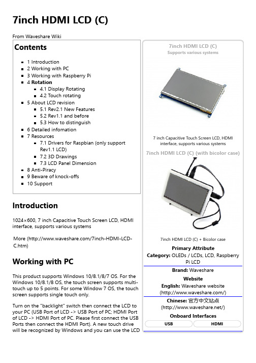
Supports various systems7inch HDMI LCD (C) (with bicolor case)With the operation above. The screen could rotate in display. However, the touch works improperly. To rotate the touch as display, you could do as below:1. install libinputsudo apt-get install xserver-xorg-input-libinput2. create an xorg.conf.d foldersudo mkdir /etc/X11/xorg.conf.d3. copy file 40-libinput-conf to the folder which we createdsudo cp /usr/share/X11/xorg.conf.d/40-libinput.conf /etc/X11/xorg.conf.d/4. Append a statement to touchscreen part of the file as below:sudo nano /etc/X11/xorg.conf.d/40-libinput.conf5. save and reboot your Pisudo rebootAfter completing these steps. The LCD could rotate 90 degree both display and touch.Note:90 degree: Option "CalibrationMatrix" "0 1 0 -1 0 1 0 0 1"180 degree: Option "CalibrationMatrix" "-1 0 1 0 -1 1 0 0 1"270 degree: Option "CalibrationMatrix" "0 -1 1 1 0 0 0 0 1"About LCD revisionAn LCD with Rev 2.1 firmware does not require any drivers, that is, touch function works properly without installing any software. So we did not provide any drivers and images for Rev 2.1 LCDs. The following drivers are only available for the LCD with Rev 1.1 firmware. But if you install the driver to the Rev 2.1 one, it will lead touch function not to work.Rev2.1 New FeaturesUpgrade to IPS screen, wider viewing angle, more clear displaying.Standard HID protocol, easy to be integrated into your system.For the Raspberry Pi, supports Raspbian, Ubuntu Mate, single touch, and driver free.When work as a computer monitor, supports Windows 10/8.1/8/7, five-points touch, and driver free.Rev1.1 and beforeFor the Raspberry Pi, comes with Raspbian driver (works with your Raspbian directly), andUbuntu image.When work as a computer monitor, touch function is unavailable.How to distinguishSee the backside of your LCD. The Revision number "Rev2.1" printed means that the LCDfirmware is Rev 2.1.However, "Rev1.1" printed on the backside doesn't mean that the LCD firmware must be Rev 1.1.Generally speaking, a LCD shipped after January 1, 2016 may be a Rev 2.1 one, although it was printed "Rev1.1".Note: The only difference between Rev 1.1 and Rev 2.1 is the firmware, but hardware solutions, placement and routing are all the same. (PCB printings might be different due to different production batches.)You can verify the firmware by these steps:1. Using Raspberry Pi: Connect the LCD to your Pi (HDMI Port of LCD -> HDMI Port of Pi; USB Port of LCD -> USB Port of Pi; 5V~2A power supply). Download the image, e.g. Raspbian, from Raspberry Pi web site (https:///downloads/). Write the image to a TF card and add the following code to the end of /boot/config.txt:max_usb_current=1hdmi_group=2hdmi_mode=87hdmi_cvt 1024 600 60 6 0 0 0hdmi_drive=1You must make sure that there are no spaces on either side of the equal sign.Save and connect the TF card to your Pi then power up. If touch works, that means the firmware revision is Rev 2.1.[Expand] [Expand] 2. Without Raspberry Pi: A PC (Windows 10/8.1/8/7) is required which cannot connect with other display device. Connect the LCD to your PC (USB Port of LCD -> USB Port of PC; HDMI Port of LCD ->HDMI Port of PC. Please first connect the USB Ports then connect the HDMI Port). If a new touch drive is recognized by Windows, that means the firmware revision is Rev 2.1. In this case, after the driver successfully installed, you can use the LCD as a human interface device.If the touch function doesn't work properly after these steps, the firmware revision is often Rev 1.1, which can also work by other methods, see Rev 1.1 Manual.Detailed infomationDepending on the firmware, please view the instructions of different revision:7inch HDMI LCD (C) (Firmware Rev 2.1) User Manual 7inch HDMI LCD (C) (Firmware Rev 1.1) User Manual(Not support Raspberry Pi 3 Model B)(/wiki/7inch_HDMI_LCD_(C)_(Firmware_Rev_1.1)_User_Manual)How to install 7inch Bicolor caseResourcesAn LCD with Rev 2.1 firmware does not require any driver, that is, touch function works properly without installing any software. So we did not provide drivers for Rev 2.1 LCDs.7inch HDMI LCD (C) image - used for the LCD with firmware Rev2.17inch HDMI LCD (C) image - used for the LCD with firmware Rev1.1Drivers for Raspbian (only support Rev1.1 LCD)Out of date, Not available for any Raspbian OS later than 27-May-2016.RPI_2B_USB_TOUCH_CAP_RASPBIAN-4.1.13-v7-7.0-1024x600-20151211.tar (https:///file/d/0B5ceUb50sIDnMzNHdXVNbFk5eE0/view?usp=sharing) (For Raspberry Pi 2 Model B)RPI_B+_USB_TOUCH_CAP_RASPBIAN-4.1.13-7.0-1024x600-20151211.tar (https:///file/d/0B5ceUb50sIDnUmJiak9qTFJsZUU/view?usp=sharing) (For Raspberry Pi B+/A+/B)RPI_2B_USB_TOUCH_CAP_RASPBIAN-3.18.16-v7-7.0-1024x600-20150910.tar (https:///file/d/0B5ceUb50sIDnY2RJbG84MkMzanM/view?usp=sharing) (For Raspberry Pi 2 Model B)RPI_B+_USB_TOUCH_CAP_RASPBIAN-3.18.16-7.0-1024x600-20150910.tar (https:///file/d/0B5ceUb50sIDnbF8tMUlrX1hZcXM/view?usp=sharing) (For Raspberry Pi B+/A+/B)3D Drawings7inch HDMI LCD B/C DrawingsLCD Panel DimensionThis page was last modified on 18 January 2018, at 09:13. This page has been accessed 143,058 times.。
- 1、下载文档前请自行甄别文档内容的完整性,平台不提供额外的编辑、内容补充、找答案等附加服务。
- 2、"仅部分预览"的文档,不可在线预览部分如存在完整性等问题,可反馈申请退款(可完整预览的文档不适用该条件!)。
- 3、如文档侵犯您的权益,请联系客服反馈,我们会尽快为您处理(人工客服工作时间:9:00-18:30)。
版本 A.2
发行编号:2014042203 日期:2014-04-22
电器性能”项目要求。 3.1-2 耐热性:
将产品放置在 70℃持续 72 小时,然后在常温常湿下放置 24 个小时后进行测试。产品 满足“1.5 机械性能”里的“操作压力” 、“透光率”和“1.5 电器性能”项目要求。 3.1-3 耐寒性: 将产品放置在-20℃持续 72 小时,然后在常温常湿下放置 24 个小时后进行测试。产品 满足“1.5 机械性能”里的“操作压力” 、“透光率”和“1.5 电器性能”项目要求。 3.1-4 冷热冲击: 将产品放置在-20℃(30min) 60℃(30min)下做 3 个循环,然后待产品常温常湿下 放置 24 个小时后,再取出进行测试。产品满足“1.3 机械性能”里的“操作压力” 、 “透光率”和“1.5 电器性能”项目要求(如下图所示)。
方式如图:
修订次数
第 9 页 共 12 页
不允许存在
2.4-4 刮痕
修订次数
第 7 页 共 12 页
版本 A.2
发行编号:2014042203 日期:2014-04-22
CRITERIA
DECISION
W<0.03mm
不计
0.03mm<W<0.05mm L<5mm,并与另一刮花或杂物之间的距离>10mm, 允许有 2 个
0.05mm<W<0.1mm
2) 当握拿Film-Glass类型的产品时,请戴上指套或手套以免锐利部分刺伤手指,因为玻 璃四周没有磨边。
【禁止事项】: ・在取出产品时,请勿握拿引线以免造成产品与引线松动。 ・请勿将产品叠放,以免引起刮花造成产品外观不良。 ・请勿将重物、硬物、尖物压于产品上。
4.4 组合上机的注意事项 1) 不要对产品施加额外的拉力。 2) 因为引线连接采用的是热压组合方式,所以不要使用额外的拉力。 【禁止事項】 安装组合时,请勿过渡翻折、重拉引线,因为重拉将使引线易从产品上剥离,习惯拉扯
2.3 电器性能 2.3-1 回路电阻 类比式:用万用表(5V)的测试头按压于引线末端,测试产品每层电极的回路电阻。确保 测试结果满足“1.5 电器性能”项目要求。 2.3-2 绝缘阻抗测试 方法一
使用高压测试机进行测试。首先预设电压值和最大电阻值为 20MΩ,然后用测试夹具 压于引线末端,确保测试绝缘阻抗大于 20MΩ。 (屏幕将显示 “pass”字样) 方法二
X方向:2000g (水平方向180度剥离)
Y 方向:500g(朝上方向90度剥离)
Z 方向:150g(铅垂方向剥离)
2.2-7 耐振动性测试 1) 操作时: 当在X,Y,Z各方向以2m/s2 的加速度,10Hz-55Hz(1分钟)频率振动,持 续30分钟,满足“1.5 电器性能”里的“绝缘阻抗”项目要求。 2) 非操作时:当在X,Y,Z各方向以20m/s2 的加速度,10Hz-55Hz(1分钟) 频率振动, 持续30分钟,满足 “1.4 机械性能”里的“操作压力”和“1.5 电器性能”项目要求。
Va= 起点输入电压
Vb= 终点输入电压
测试力:120gf
备注:测试区域为动作区(AA)内缩 2.5mm
最大电流值
25mA(DC 25V)
Positions B
绝缘阻抗
>20MΩ
触点抖动时间
<10ms
1.6 外观 形状和尺寸:按图档说明 构造和区域定义:T/P结构与外观确保(见附件图纸)
2 试验条件
发行编号:2014042203 日期:2014-04-22
TOUCH PANEL Film/ Glass Specification
我司编号: BX-TPM7115
客户型号:
编制
审核
REPORTED
CHECKED
品质 QUALITY
客户承认
签字盖章: 日 期:
修订次数
第 1 页 共 12 页
号新
版本 A.2
1.3 光学特性 项目
全光线透光率 雾值
性能 75%以上 8%以下
备注
1.4 机械性能 项目
操作压力 操作寿命 表面硬度
敲击寿命 笔画寿命
值 ≤60-120g
>3H
>1,000,000 次 >1,000,000 次
修订次数
第 4 页 共 12 页
版本 A.2
1.5 电器性能 项目
最大电压值 端子间阻抗
4 使用过程中的注意事项
为了避免不良事故的发生和产品性能的破坏,请遵守如下警告及禁止事项。 4.1 储存的注意事项:
储存产品时须按样品承认书的温湿度要求放置,注意不可受日光直射或重物重压。 4.2 卸货的注意事项:
卸货前请注意产品外包装的方向性。 4.3 搬运的注意事项:
1) 须保持产品的透明清晰度,因而请在接触产品之前戴上清洁的指套、手套和面罩以免 留下指纹或污点,并且握拿产品时请握住产品的四周。
X
宽Y Y≤0.8
厚度 Z Z≤T
判定
0片,若有任何碎 裂或裂纹超过所 给 的 X,Y,Z 值 则何渐裂或裂纹,不接受
2.4-7保护胶印 保护胶印长度<4mm,允收,其它按照刮伤标准检验。 保护胶印在VA区外,允许
2.4-8其它 此承认书基本满足产品特性要求,若有其它问题可针对客户实际要求进行协商。
规格 163.6(L)×102.8(W)×1.4(T)
156.5(L)×94.8(W) 155.5(L)×93.8(W) Pitch 3×3 φ0.06
单位 mm
mm mm
1.2 环境参数 项目
工作温湿度 储存温湿度
值(条件) -10℃-+60℃,<90%RH -20℃-+70℃,<90%RH
备注 单体状态下 单体状态下
6 附件
修订次数
第 3 页 共 12 页
版本 A.2
1 样品规格 1.1 特征和规格 特征
结构
上线
下线
发行编号:2014042203 日期:2014-04-22
所用材料 ITO 导电薄膜 ITO 导电玻璃
注释 雾面单层导电薄膜,厚度 0.188mm
强化导电玻璃,厚度 1.1mm
规格
项目 外形尺寸 可视区(V/A) 动作区(A/A) 绝缘点大小及间距
用绝缘表(25V)的测试头按压于引线末端,测试产品的绝缘阻抗。确保绝缘阻抗大于 20 MΩ。 2.3-3 线性测试(只是针对类比式产品而言)
修订次数
第 6 页 共 12 页
版本 A.2
发行编号:2014042203 日期:2014-04-22
用线性测试机进行测试确保读数小于等于 2.5 2.4 外观检验标准
1) 矩阵式、四线电阻式: 使用φ2、60°的橡皮头,80g 的力度、频率 2 次/秒来回敲击 50 次后,满足“1.5 电器性能”。
2.2-2 笔画寿命 (备注:画线的位置应位于 AA 区以内,距离 AA 区边缘>3mm.)
1) 四线电阻式:使用φ2 聚纤维酯笔、80g 的力度、以频率为 60mm/s 在相同的位置 (10-100mm)笔画 10 万后,满足“1.5 电器性能”项目要求。
2.2-3 操作压力: 小于 120g(用φ2 的聚纤维酯笔操作)
修订次数
第 5 页 共 12 页
版本 A.2
发行编号:2014042203 日期:2014-04-22
(备注:由绝缘点的间距及大小来决定操作压力的大小.) 2.2-4 耐冲击试验 测试条件
当用 64g, φ25.4mm 钢球从 12-60cm 的高度垂直跌落在玻璃厚度为 0.7-3.0mm 的产 品表面中心一次,玻璃不会损坏。此试验只适用于 Film+Glass 类型的产品。 (备注:我司是以每隔10cm为一个测试高度,逐步增加让钢球自由落下,记录钢球击 碎T/P时之高度。) 判定基准 在规定的条件下或客户指定的条件下,产品各项特性基本满足,比较未有明显变化并且 变动率小于20% 。 2.2-5 耐静压性测试 测试条件 使用拉压力计的平头测试头(直径为15mm)对玻璃厚度为 0.7-3.0mm 的产品表面中 心垂直施加8-20kg/cm2 压力,确保玻璃不毁坏破裂。此试验只适用于Film+Glass类型 的产品。(备注:我司是针对不同厚度的玻璃,以均匀的压力逐步加压于T/P的表面,观 察记录T/P破裂高度。) 判定基准 在规定的条件下或客户指定的条件下,产品各项特性基本满足,无明显变化。 2.2-6 引线拉力测试:
L<5mm,不允许存在
2.4-5牛顿环
规律性(圆圈形)允许出现小于 1/5 区域的 1 个,无规律性(非圆圈形)不允许出现 2.4-6玻璃破角:T为玻璃厚度
角
长X
宽Y
厚度 Z
判定
Y
X≤1.0
X
Y≤1.0
Z≤T
0片,若有任何碎 裂或裂纹超过所 给 的 X,Y,Z 值 则 不接受
角以外的地方
长X
Y
X≤1.0
并且在产品的下方加以黑色的纸板作为衬托背景,每片产品检测时间不超过 10 秒,如图:
A source of light(12-20W)
光源
300-400mm
Eyes
眼睛
400-500mm
45
2.4-2 黑点、白点、点状脏物
CRITERIA
DECISION
φ≤0.10 0.1mm<φ<0.25mm
Φ>0.25mm
直线性
值 10V(直流)
以图纸 ﹤2.0
发行编号:2014042203 日期:2014-04-22
备注
测试方法如下图
X-Axis
V
Measured Volume:Vx Vx Voltage