DR635 说明书
NSR616RF-D01线路距离保护测控装置-技术使用说明书V3.11

第五章 保护功能 .......................................................................................................................................... 11
UC635 AVC装置说明书

第七章UC635 AVC装置第一节电厂AGC/AVC/EGS基础 (2)1.1 AGC系统 (2)1.2 AVC系统 (2)1.3 EGS系统 (3)第二节 UC635 AVC装置结构 (4)2.1 POWER AVC 3000系统产品形式 (4)2.2 UC635 AVC特点 (4)2.3 UC635 AVC结构 (6)第三节 PowerAVC 3000系统功能 (11)3.1 UC635 AVC调节原理 (11)3.2 UC635 AVC控制方式 (12)3.3 UC635 AVC保护策略 (12)3.4 PowerAVC 3000系统功能描述 (13)3.5 PowerAVC 3000系统技术指标 (19)第四节 UC635 AVC装置调试 (19)4.1 硬件检查 (19)4.2 装置上电 (19)4.3 硬件初始化 (21)4.4 软件配置 (24)4.5 AVC参数确定 (24)4.6 AVC现场调试的准备 (25)4.7AVC 现场调试 (26)第一节电厂AGC/AVC/EGS基础1.1 AGC系统发电厂生产运营的目的,首先是将发电机组转换成的电能量,发往电力公司所属的电网,供接入的负载用户使用。
发电机组发出的电能量(称机组有功),是无发储存的,所以要并网发电。
但是对于一个区域电网来说,一个电厂机组发电量需要多少?能发多少量?如何自动控制与调节?这就需要AGC系统完成。
它的控制权是调度主站。
AGC是自动发电控制Automatic Generator Control简称。
由远方调度通过SCADA数据通信/通道,下发AGC指令值到电厂远动装置,再由远动装置AGC指令转换成4-20mA电流信号送至厂内DCS发电机组协调控制系统,最终由DCS完成对机组的发电出率控制。
一般来说,AGC是一个开环控制系统,是由调度人员分别在不同的时段,根据当前机组实发有功功率与计划值比较,将修整的指令值下发电厂AGC系统完成的。
D-LINK DIR-635中文安装说明书

D-link DIR-635 中文设置界面详解产品特征:-新增支持SharePort功能(即可支持外接USB设备,如移动硬盘、U盘,打印服务器、扫描仪)-应用了MIMO、OFDM以及增大信道带宽等多项先进技术,使得最大传输数量可以达到300Mbps。
-获奖的QoS 引擎和最近的draft 802.11n 技术产生完美的网络性能。
-符合802.11n,并且向下兼容802.11g和802.11b的所有无线设备。
-3根外置可反折SMA天线。
-1个百兆W AN口、4个百兆LAN口均支持MDI/MDI-X技术。
-支持UPnP、DDNS、静态路由、VPN Pass-through。
-支持虚拟服务器、特殊应用程序和DMZ主机等多种端口转发,可用于建设内网网站。
-支持SSID广播控制、基于MAC地址的访问控制列表。
-更多的带机量,DIR-635拥有高达100-110M 的传输速率,可以在不影响速度的情况下,带更多的用户。
-更先进的WEPTM, WPA TM, or WPA2TM 加密技术保护您的网络。
-更安全的WCN,1个USB2.0接口配合无线存储安全技术,备份您的配置资料。
-更方便的D-Link 路由器安装精灵。
-保持信号独立,不会和周围的其他无线信号互相干扰性能优于11g 650%的无线路由器D-Link 的无线路由器(DIR-635)是一个款符合802.11n 的设备,比802.11g 连接速度更快,性能相当于它的650%并且超过传统的100Mbps有线以太网络。
您可以在你的家里创建一个无线网路,一起来分享相片,文件,音乐,视频,打印机和网络存储设备。
D-Link的QoS 技术将有线、无线的数据分析并分隔成多层数据流。
这个数据流按照它的重要性分级,所以像V oIP、视频服务、在线游戏的数据优先级就比网页浏览的要高。
这样的应用会使得您应用网络更加流畅。
完整家庭覆盖范围这个高性能的路由器提供出众的覆盖范围,消除死角。
晶体管说明书:Diodes Incorporated DMP6350S 60V P-CHANNEL
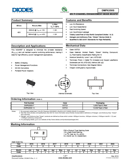
Description and ApplicationsThis MOSFET is designed to minimize the on-state resistance (R DS(ON)) and yet maintain superior switching performance, making it ideal for high-efficiency power management applications. ∙ Battery Charging∙ Power Management Functions ∙ DC-DC Converters ∙ Portable Power AdaptorsFeatures and Benefits∙ Low On-Resistance ∙ Low Input Capacitance ∙ Fast Switching Speed ∙ Low Input/Output Leakage∙ Totally Lead-Free & Fully RoHS Compliant (Notes 1 & 2) ∙ Halogen and Antimony Free. “Green” Device (Note 3) ∙Qualified to AEC-Q101 Standards for High ReliabilityMechanical Data∙ Case: SOT23∙ Case Material: Molded Plastic, “Green” Molding Compound. UL Flammability Classification Rating 94V-0 ∙ Moisture Sensitivity: Level 1 per J-STD-020∙ Terminals: Finish − Matte Tin Annealed over Copper Leadframe. Solderable per MIL-STD-202, Method 208 ∙ Terminals Connections: See Diagram Below ∙Weight: 0.009 grams (Approximate)Ordering Information (Note 4)Notes: 1. No purposely added lead. Fully EU Directive 2002/95/EC (RoHS) & 2011/65/EU (RoHS 2) compliant.2. See /quality/lead_free.html for more information about Diodes Incorporated’s definitions of Halogen - and Antimony-free, "Green" and Lead-free.3. Halogen- and Antimony-free "Green” products are defined as those which contain <900ppm bromine, <900ppm chlorine (<1500ppm total Br + Cl) and<1000ppm antimony compounds.4. For packaging details, go to our website at /products/packages.html.Marking InformationTop View Internal SchematicTop ViewP35 = Product Type Marking Code YM = Date Code Marking Y or Y= Year (ex: D = 2016) M = Month (ex: 9 = September)DSGP35Y MMaximum Ratings(@T A = +25°C unless otherwise specified.)Thermal CharacteristicsElectrical Characteristics(@T A = +25°C unless otherwise specified.)Notes: 5. Device mounted on FR-4 substrate PC board, 2oz copper, with minimum recommended pad layout.6. Device mounted on FR-4 substrate PC board, 2oz copper, with 1inch square copper plate.7. Short duration pulse test used to minimize self-heating effect.8. Guaranteed by design. Not subject to product testing.4.0-50-25 0 25 50 75 100 125 150R D S (O N ), D R A I N -S O U R C E O N -R E S I S T A N C E (Ω)T J , JUNCTION TEMPERATURE (℃)Figure 7. On-Resistance Variation with JunctionTemperaturePackage Outline DimensionsPlease see /package-outlines.html for the latest version.SOT23Suggested Pad LayoutPlease see /package-outlines.html for the latest version.SOT23All 7°。
VDX-6354用户手册
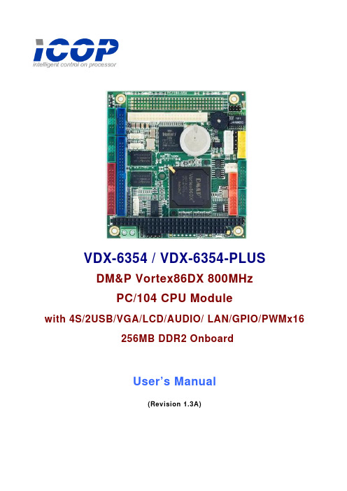
VDX-6354 / VDX-6354-PLUSDM&P Vortex86DX 800MHzPC/104 CPU Modulewith 4S/2USB/VGA/LCD/AUDIO/ LAN/GPIO/PWMx16256MB DDR2 OnboardUser’s Manual(Revision 1.3A)CopyrightThe information in this manual is subject to change without notice for continuous improvement in the product. All rights are reserved. The manufacturer assumes no responsibility for any inaccuracies that may be contained in this document. And makes no commitment to update or to keep current the information contained in this manual.No part of this manual may be reproduced, copied, translated or transmitted, in whole or in part, in any form or by any means without the prior written permission of the ICOP Technology Inc..©Copyright 2008 ICOP Technology Inc.Manual No. IUM6354000-01 Ver.1.0A December, 2008Manual No. IUM6354000-01 Ver.1.1A February, 2009Manual No. IUM6354000-01 Ver.1.2A September, 2009Manual No. IUM6354000-01 Ver.1.3A October, 2010Trademarks AcknowledgmentVortex86DX™ is the registered trademark of ICOP Technology Inc.Other brand names or product names appearing in this document are the properties and registered trademarks of their respective owners. All names mentioned herewith are served for identification purpose only.T a b l e o f C o n t e n t sT a b l e o f C o n t e n t s (iii)C h a p t e r 1 Introduction (1)1.1 Packing List (1)1.2 Product Description (2)1.3 Specifications (3)1.4 Board Dimension (5)C h a p t e r 2 Installation (6)2.1 Board Outline (6)2.2 Connectors & Jumpers Location (7)2.3 Connectors & Jumpers Summary (9)2.4 Pin Assignments & Jumper Settings (11)2.5 System Mapping (22)2.6 Watchdog Timer (25)2.7 GPIO (26)2.8 SPI flash (27)2.9 PWM (28)3.0 IDE to SD (29)C h a p t e r 3 Driver Installation (30)Appendix (31)A. TFT Flat Panel Data Output (31)B. TFT Flat Panel Support List (32)C. LVDS Flat Panel Support List (34)D. Flat Panel Wiring and Lighting (35)E. TCP/IP library for DOS real mode (36)F. BIOS Default Setting (37)Warranty (38)C h a p t e r 1Introduction 1.1 Packing ListProduct Name PackageVDX-6354&VDX-6354-PLUSEmbedded Vortex86DX CPU All-in-One Board Manual & Drivers CD x 1RS232 cable x 4PRINTER cable x1IDE cable x 1USB cable x 1 (USB port x 2)VGA cable x 1LAN cable x 1GPIO cable x 1AUDIO Line x2PS/2 Mouse cable x 1PS/2 Keyboard cable x 1Screw Kit x 11.2 Product DescriptionThe VDX-6354 family of low-power x86 embedded controller is designed to meet PC/104 specification, and integrated with the following features.800 MHz Vortex86DX SoCVGA, TFT/ LVDS LCD support up to 1280x1024 resolution256 / 512MB DDR2 system memory Enhanced IDE (UltraDMA-100/66/33) 10/100Mbps Ethernet2 USB 2.0 (host)Up to 4 serial portsParallel port16-bit GPIOs AudioOnboard 4MB SPI FlashPC/104-Plus expansion busMeet PC/104 stacking spec.2 watchdog timerPWM 16~24 channelsJTAG interfaceAMI BIOSSingle voltage +5V DCSupport extended operatingtemperature range of -20°C to +70°CThe VDX-6354 PC/104 family of embedded controller is designed with backward compatibility in mind, to provide migration path for projects facing end-of-life challenges with their existing x86 based PC/104 controller. The VDX-6354 family of controller is designed as a plug in replacement, with backward compatibility to support legacy software to help extend existing product life cycle without heavy re-engineering.VDX-6354 is suitable for broad range of data-acquisition, Industrial automation, Process control, Automotive controller, AVL, Intelligent Vehicle management devic,Medical device, Human machine interface, Robotics, machinery control And more…application that required small footprint, low-power and low-cost hardware with open industry standard such as PC/104.1.3 SpecificationsFeatures VDX-6354CPU DM&P SoC CPU Vortex86DX- 800MHzReal Time Clock with Lithium Battery Backup Cache L1:16K I-Cache, 16K D-Cache L2:128KB CacheBIOS AMI BIOSBus Interface PC/104 Standard Compliant (Optional: PCI-104)System Memory 256 / 512MB DDR2 OnboardWatchdog Timer Software programmable from 30.5 us to 512 seconds x2sets(Watchdog 1 fully compatible with M6117D) VGA XGI Volari Z9s ChipsetVGA and TFT Flat Panel Interface SupportLVDS Flat Panel Interface Support (Optional)Onboard 32MB VGA MemorySupport resolution up to 1280 x 1024,16MB colors LAN Integrated 10/100M EthernetAUDIO CM119 USB Audio controllerI /O Interface Enhanced IDE port (UltraDMA-100/66/33) x1 RS-232 port x3RS-232/422/485 port x1 (RS485: Auto Direction) Parallel port x1USB port x2 (USB 2.0 version)16-bit GPIO port x110/100Mbps Ethernet port x1Connectors 2.00 mm ∅ 44-pin box header for IDE x12.00 mm ∅ 44-pin box header for LCD x 12.00 mm ∅ 10-pin box header for VGA x12.00 mm ∅ 10-pin box header for USB x12.00 mm ∅ 26-pin box header for Printer x12.00 mm ∅ 20-pin box header for 16-bit GPIO x12.00 mm ∅ 10-pin box header for RS-232 x42.00 mm ∅ 8-pin header for Ethernet x 12.54 mm ∅ 5-pin box header for Keyboard x12.54 mm ∅ 5-pin header for Mouse x12.54 mm ∅ 4-pin header for DC-in x12.54 mm ∅ 3-pin header for RS-485 x12.54 mm ∅ 2-pin header for Reset x12.54 mm ∅ 7-pin header for Redundancy x1(Opt)2.54 mm ∅ 2-pin header for SYS-Fail-SW- x1(Opt)1.25 mm ∅ 6-pin Wafer for JTAG x11.25 mm ∅ 4-pin Wafer for Line-out/MIC-in x2Flash Disk Support Onboard 4MB SPI Flash Disk (Driver: A)44-pin IDE Flash Disk( EmbedDisk 16MB or above)44-pin IDE to Micro SD (Optional)PWM 16~24 channelsPower Requirement Single Voltage +5V@740mADimension 90 X 96mm (3.54 x 3.77 inches)Weight 90gOperating Temperature -20o C ~ +70o C-40°C ~ +85°C (Optional)1.4 Board DimensionC h a p t e r 2Installation2.1 Board Outline(Note1: COM2 RS232/422/485 is selected by BIOS setting) (Note2: PCI-104 connector is optional)(Note3: VI/O Default setting of PCI-104 connector is +5V) (Note4: VDX-6354-512 is optional)(Note5: Redundancy Signal and System-Fail-SW are optional)2.2 Connectors & Jumpers Location ConnectorsJumpers & LEDs2.3 Connectors & Jumpers SummarySummary TableNbr Description Type of Connections Pin nbrs.J1 IDE Box Header, 2.0∅ ,22x2 44-pinJ2 USB Box Header,2.0∅ , 5x2 10-pinJ4 LAN Pin Header, 2.0∅ , 4x2 8-pinJ5 JTAG Wafer, 1.25∅ , 6x16-pinJ6 Reset Pin Header, 2,54∅,1x2 2-pinJ7 Redundancy (Optional) Pin Header, 2.54∅, 7x1 7-pinJ8 System –Fail-Switch (Optional) Pin Header, 2.54∅ , 2x1 2-pinJ9 PS/2 Keyboard Box Header, 2,54∅,1x5 5-pinJ10 PS/2 Mouse Pin Header, 2,54∅,1x5 5-pinJ11 COM1(TTL/GPIO-P4 / PWMx8) Box Header, 2.0∅ 5x2 10-pinJ12 COM2(RS232/422/485) Box Header, 2.0∅ 5x2 10-pinJ13 GPIO ( Port 0 / 1 /PWMx16) Box Header, 2.0∅ ,10x2 20-pinJ15 RS-485 (Auto direction) Molex Header,2.54∅, 3x1 3-pinJ16 Power Connector Terminal Block 5.0∅,2x1 2-pinJ17 COM3 Box Header, 2.0∅ 5x2 10-pinJ18 PRINT Box Header, 2.0∅ , 13x2 26-pinJ19 COM4 Box Header, 2.0∅ 5x2 10-pinJ20 PC104 Connector – 64 pin Box Header, 2.54∅ 32x2 64-pinJ21 PC104 Connector – 40 pin Box Header, 2.54∅ 20x2 40-pinJ22 4P Power Source (InterconnectPin Header, 2.54∅ , 4x1 4-pin to PC/104 – J20)J23 PC/104 + (Optional) Box Header, 2.0∅ , 30x4 120-pinJ24 VGA Pin Header, 2.0∅ ,5x2 10-pinJ25 LCD Connector Box Header,2.0∅ ,22x2 44-pinJ33 LINE-OUT Wafer, 1.25∅ , 4x14-pinJ34 MIC-IN Wafer, 1.25∅ , 4x14-pinPWR-Power Active LED (Red) LED-SMDLEDIDE-IDE Active LED (Green ) LED-SMDLEDMTBF-MTBF-Out (Orange) LED-SMDLEDLED 3 LAN Link/Active LED (Green) LED-SMD LED 4 LAN Duplex LED ( Yellow ) LED-SMD SP1 BUZZER2.4 Pin Assignments & Jumper SettingsJ1: IDE (44 Pins)J2: USB Pin # Signal Name Pin # Signal Name1 VCC2 VCC3 LUSBD3-4 LUSBD2-5 LUSBD3+6 LUSBD2+7 GND8 GND9 GGND 10 GGND Pin # Signal Name Pin # Signal Name1 IDERST2 GND3 IDED74 IDED85 IDED6 6 IDED97 IDED58 IDED109 IDED4 10 IDED11 11 IDED3 12 IDED12 13 IDED2 14 IDED13 15 IDED1 16 IDED14 17 IDED0 18 IDED15 19 GND 20 NC 21 IDEREQ 22 GND 23 IDEIOW 24 GND 25 IDEIOR 26 GND 27 ICHRDY 28 GND 29 IDEACK 30 GND 31 IDEINT 32 NC 33 IDESA1 34 IDECBLID 35 IDESA0 36 IDESA2 37 IDECS-0 38 IDECS1 39 IDELED 40 GND 41 VCC 42 VCC 43 GND 44 NCJ4: LANPin # Signal Name Pin # Signal Name1 ATX+2 ATX-3 ARX+4 LED05 LED0+6 ARX-7 LED1+ 8 LED1J5: JTAGPin # Signal Name Pin # Signal Name1 VCC2 GND3 TCK4 TDO5 TDI6 TMSJ6: RESETPin # Signal Name Pin # Signal Name1 RST_SW2 GNDJ7: Redundancy (Optional)Pin # Signal Name Pin # Signal NameSYS-FAIL-OUT1 GND 23 SYS-FAIL-IN4 GPCS05 SYS-GPCS-IN6 TXD9\7 RXD9\J8: System-Fail-Switch (Optional)Pin # Signal Name1 SYS-SW-IN2 GNDJ9: PS/2 KeyboardPin # Signal Name Pin # Signal Name1 KBCLK2 KBDAT3 NC4 GND5 VCCJ10: PS/2 MousePin # Signal Name Pin # Signal Name1 MSCLK2 MSDATA3 NC4 GND5 VCCJ11: COM 1 (Optional TTL/ GPIO-P4 / PWMx8)Pin # SignalNamePin #SignalName1 DCD12 RXD13 TXD14 DTR15 GND6 DSR17 RTS1 8 CTS19 RI1 10 NCJ12: COM2 RS232 / 422 / 485 (Optional: TTL)Pin # Signal Name Pin # Signal Name1 DCD2/ 422TX- / RS485-2 RXD2 / 422TX+ / RS485+3 TXD2/422RX+ 4 DTR2/422RX-5 GND6 DSR27 RTS28 CTS29 RI2 10 NCJ13: GPIO (Port 0 / 1/ PWMx16)Pin # Signal Name Pin # Signal Name1 GND2 VCC3 GP004 GP105 GP016 GP117 GP02 8 GP129 GP03 10 GP1311 GP04 12 GP1413 GP05 14 GP1515 GP06 16 GP1617 GP07 18 GP1719 VCC 20 GNDJ15: RS485 (Auto direction)Pin # Signal Name1 RS485+2 RS485-3 GNDJ16: Power Connector (Terminal Block 5.0mm) Pin # Signal Name1 +5V2 GNDJ17: COM3 (Optional: TTL)Pin # Signal Name Pin # Signal Name1 DCD32 RXD33 TXD34 DTR35 GND6 DSR37 RTS3 8 CTS39 RI3 10 NCJ18: PRINTPin # Signal Name Pin # Signal Name1 STB- 14 AFD-2 PD0 15 ERR-3 PD1 16 INIT-SLIN-4 PD2 175 PD3 18 GND6 PD4 19 GND7 PD5 20 GND8 PD6 21 GND9 PD7 22 GND10 ACK- 23 GND11 BUSY 24 GND12 PE 25 GND13 SLCT 26 NCJ19: COM4 (Optional: TTL)Pin # Signal Name Pin # Signal Name1 DCD42 RXD43 TXD4 4 DTR45 GND6 DSR47 RTS4 8 CTS49 RI4 10 NCJ20: PC104 Connector – 64pinPin # Signal Name Pin # Signal Name* 2 GND1 IOCHCHKRESETDRV3 SD7 45 SD6 6 VCC7 SD5 8 IRQ99 SD4 10 -5V 11 SD3 12 DRQ2 13 SD2 14 -12V 15 SD1 16 OWS 17 SD0 18 +12V 19 IOCHRDY 20 GNDSMEMW*21 AEN 22*SMEMR 23 SA19 24* 25 SA18 26 IOW* 27 SA17 28 IOR* 29 SA16 30 DACK3 31 SA15 32 DRQ3* 33 SA14 34 DACK1 35 SA13 36 DRQ1*REFRESH 37 SA12 3839 SA11 40 SYSCLK 41 SA10 42 IRQ7 43 SA9 44 IRQ6 45 SA8 46 IRQ5 47 SA7 48 IRQ4 49 SA6 50 IRQ3DACK2* 51 SA5 5253 SA4 54 TC 55 SA3 56 BALE 57 SA2 58 VCC 59 SA1 60 OSC 61 SA0 62 GND 63 GND 64 GNDJ21: PC104 Connector – 40pinJ22: 4P Power Source (Interconnect to PC/104 – J20) Pin # Signal Name1 -5V2 -12V3 +12V4 GNDPin # Signal Name Pin # Signal Name1 GND2 GND3 MEMCS16 *4 SBHE *5 IOCS16 * 6 SA237 IRQ10 8 SA229 IRQ11 10 SA2111 IRQ12 12 SA2013 IRQ15 14 SA1915 IRQ14 16 SA1817 DACK0 * 18 SA1719 DRQ0 20 MEMR *21 DACK5 * 22 MEMW *23 DRQ5 24 SD825 DACK6 * 26 SD927 DRQ6 28 SD1029 DACK7 * 30 SD1131 DRQ7 32 SD1233 VCC 34 SD1335 MASTER * 36 SD1437 GND 38 SD1539 GND 40 NCJ23: PC/104 + (Optional)VI/O Default setting: +5VIf you need to use VI/O as +3.3V, please see the page 19. Pin # A B C D1 GND NC +5V AD002 VI/O(+5V) AD02 AD01 +5V3 AD05 GND AD04 AD034 C/BE0# AD07 GND AD065 GND AD09 AD08 GND6 AD11VI/O(+5V) AD10 GND7 AD14 AD13 GND AD128 +3.3V C/BE1# AD15 +3.3V9 SERR# GND NC PAR10 GND PERR# +3.3V NC11 STOP# +3.3V LOCK# GND12 +3.3V TRDY# GND DEVSEL#13 FRAME# GND IRDY# +3.3V14 GND AD16 +3.3V C/BE2#15 AD18 +3.3V AD17 GND16 AD21 AD20 GND AD1917 +3.3V AD23 AD22 +3.3V18 IDSEL0 GND IDSEL1 IDSEL2VI/O(+5V) IDSEL319 AD24 C/BE3#20 GND AD26 AD25 GND21 AD29 +5V AD28 AD2722 +5V AD30 GND AD3123 REQ0# GND REQ1# VI/O(+5V)24 GND REQ2# +5V GNT0#25 GNT1# VI/O(+5V) GNT2# GND26 +5V CLK0 GND CLK127 CLK2 +5V CLK3 GND28 GND INTD# +5V RST#29 +12V INTA# INTB# INTC#30 -12V NC NC GNDPlease remove the 0 ohm (1206 type) of R212 and add 0 ohm (1206 type) on R213J24: VGAPin # SignalNamePin #SignalName1 ROUT 2 GND3 GOUT 4 GND5 BOUT 6 GND7 HSYNC 8 GND9 VSYNCD 10 GNDJ25: LCD (DVO) ConnectorPin # Signal Name Pin # Signal Name1 +3.3V2 +3.3V3 LG24 LG35 LG46 LG57 NC 8 NC9 LR0 10 LR111 LR2 12 LR313 LR4 14 LR515 GND 16 NC17 NC 18 NC19 NC 20 GND21 NC 22 NC23 LB0 24 LB125 LB2 26 LB327 LB4 28 LB529 NC 30 NC31 LG0 32 LG133 GND 34 GND35 NC 36LCLK37 NC 38 LDE39 NC 40LHSYNC41 NC 42LVSYNC43 LBACKL 44 LVDDEN(Please refer to Appendix A, for TFT Flat Panel Data Output)J33: LINE OUTPin # Signal Name1 LOUTR2 GND3 GND4 LOUTLJ34: MIC-INPin # Signal Name1 MICVREF2 GND3 GND4 MIC-IN2.5 System Mapping2.6 Watchdog TimerThere are two watchdog timers in Vortex86SX/DX CPU. One is compatible with M6117D watchdog timer and the other is new. The M6117D compatible watchdog timer is called WDT0 and new one is called WDT1.We also provide DOS, Linux and WinCE example for your reference. For more technical support, please visit: /tech or download the PDF file:/tech/vortex86dx/2.7 GPIO (General Purpose Input / Output)40 GPIO pins are provided by the Vortex86SX/DX for general usage in the system. All GPIO pins are independent and can be configured as inputs or outputs, with or without pull-up/pull-down resistors.We also offer DOS, Linux and WinCE example for your reference. For more technical support, please visit: /tech or download the PDF file:/tech/vortex86dx/2.8 SPI flash (Serial Peripheral Interface)As SPI Flash (Serial Peripheral Interface) offers many benefits including: reduced controller pin count, smaller and simpler PCBs, reduced switching noise, less power consumption, and lower system costMany of users may consider using a formatted SPI flash to boot for the system or emulate SPI flash as Floppy (A: Driver or B: Driver). Then you must know how to set for this condition in CMOS Setup and boot up under DOS 6.22, X-DOS, DR-DOS and Free DOS.For more technical support, please visit: /tech or download the PDF file: /tech/vortex86dx/2.9 PWM (Pulse-width modulation)Pulse-width modulation (PWM) of a signal or power source involves the modulation of its duty cycle, to either convey information over a communications channel or control the amount of power sent to a load.The popular applications of pulse width modulation are in speed control of electric motors, volume control of Class D audio amplifiers or brightness control of light sources and many other power electronics applications.The Vortex86DX SoC integrated 32 channels of PWM interface enabling the Automation, robotic industry to a New Age x86 SoC platform and we also offer the sample code of PWM which will guide the engineer to control the PWM functionality smoothly.For more inquire of this sample code that please contact our sales team or mail to:info@3.0 IDE to SD (Micro-SD)Vortex86DX SoC also built-in simulation circuit to adapt SD to IDE in order to allow your system to recognize Micro-SD card as C: or D: DriverSD-1917: 44 pins IDE to SD Adapter is an ideal solution for industrial PC or embedded system and 44 pins IDE to SD Adapter can be easily installed on all Vortex86DX-63xx CPU boards. You or your customers just do the BIOS setting and use SD-1917 to connect IDE connector of Vortex86DX-63xx directly.For further inquiries of SD-1917, please contact ICOP sales team or mail to: info@ for your request.<BIOS setting>Get into the BIOS setup UtilityChoose Primary IDE Pin Select: SD cardPress “F10” to Save configuration changes and exit setupSD-1917SD-1917: /pddetail.aspx?id=125&pid=4C h a p t e r 3Driver InstallationVGAThe Vortex86DX processor also use external Display chip ““Volari™ Z9s” which is an ultra low powered graphics chipset with total power consumption at around 1-1.5 W. It is capable in providing VGA display output upto 1600x1200. With DVO interface, developers could easily connect flat Panel to support TFT and LVDS output.LANThe Vortex86DX processor also integrated 10/100Mbps Ethernet controller that supports both 10/100BASE-T and allows direct connection to your 10/100Mbps Ethernet based Local Area Network for full interaction with local servers, wide area networks such as the Internet.I/O and IRQ settings can be done by software with the supplied utility software, or it can be set for Plug and Play compatibility. The controller supports: Half / Full-Duplex Ethernet function to double channel bandwidth, auto media detection.AUDIOCM119 is a highly integrated single chip USB audio controller specifically for VoIP (Voice over internet protocol) application. All essential analog modules are embedded in CM119, including dual DAC and earphone driver, ADC, microphone booster, PLL, regulator, and USB transceiver.8 GPIO pins can constitute a 24 key matrix directly support keypad control function without MCU.Many features are programmable with jumper pins or external EEPROM. Vender can customize unique USB VID/PID to EEPROM for VoIP software authentication. Moreover, individual unique phone number for each device is possible via serial number stored in external EEPROM.Operating system supportThe Vortex86DX-6354 PC/104 CPU board supports Embedded software: Free DOS, DOS 6.22, PCDOS 7.1, DR-DOS, x-DOS, OS/2, Windows CE 6.0, Windows 98, Windows XP Professional, Windows Embedded standard (XPE) and Windows 2000 (SP4).Please get the drivers from the Driver CD which attached with the standard packing ofVortex86DX-6354 board or please get it from DMP official website:/tech/vortex86dx/Vortex86DX-6354 also supports most of the popular Linux distributions, for more detail information, please visit DMP official website: /tech/vortex86dx/Appendix A. TFT Flat Panel Data OutputB. TFT Flat Panel Support ListSize Brand Resolution Model No.image 320x240 FG050701DSSWBG015.7” Data5.7” Optrex 320x240 55264GD057J-FW-ABN5.7” TOSHIBA 320x240 LTA057A343F5.7” Sharp 320x240 (QVGA / VGA) LQ057Q3DC02(QVGA / VGA) TCG057QV1AC-G105.7” Kyocera 320x240(QVGA / VGA) PD057VU4 /U55.7” PVI 320x240image 640x480 FG050710DSSWJG01/DG015.7” Data5.7” Ampire 640x480 AM-640480GTMQW-T00H5.7” URT 640x480 UMSH-8004MD-T5.7” Sharp 640x480 LQ057V3DG015.7” CPT 640x480 CLAA057VA016.4” PVI 640x480 V16C6448AC6.4” LG-PHILIPS 640x480 LB064V02/VT5/VT46.4” PVI 640x480 PD064VT26.4” Sharp 640x480 LQ064V3DG017” AUO 800x480 C070VW02V0image 800x480 FG0700A0DSSWBG01 7” Data7” LG-PHILIPS 800x480 (TFT 24 bits) LB070WV17” HITACHI 800x480 TX18D57VM2BAA 7” Samsung 800x480 LMS700KF057” PVI 800x480 PM070WL4 7” URT 800x480 UMSH-8173MD-1T HSIN 800x480 LW700AT9309 7” CHI8” Sharp 640x480 LQ080V3DG01Size Brand Resolution Model No.V024bits) A080SN01(TFT8” AUO 800x6008.4” Sharp 800x600 LQ084S3DG01 10.4” PVI 640x480 PD104VT1/VT2 10.4” NEC 640x480 NL6448AC33-18 10.4” NEC 640x480 NL6448AC33-29 10.4” NEC 640x480 NL6448BC33-59 10.4” Sharp 640x480 LQ104V1DG51/DG61 10.4” Sharp 640x480 LQ10d368 11” Sharp 800x480 LQ110Y3DG01 12.1” NEC 800x600 NL8060BC31-01C. LVDS Flat Panel Support ListIf you would like to use LVDS Flat Panel with Vortex86SX / Vortex86DX series, please contact our regional sales to get ICOP-0096 information or visit ICOP website:/pddetail.aspx?id=65&pid=4ICOP–0096: 18-bit TFT to LVDS converter and Cable-LVDS-30: LVDS Cable 30cmApproved LVDS Flat Panel ListSize Brand Resolution Model No.3.5” PVI 640x480 PD035VL15” PVI 640x480 PD050VL16.5” AUO 640x480 G065VN018.4” AUO 800x600 G084SN038.9” AUO 1024x600 A089SW018.9” CPT 1024x600 CLAA089NA0ACW10.4” AUO 800x600 G104SN0212.1” AUO 800x600 G121SN0115” AUO 1024x768 G150XG01D. Flat Panel Wiring and LightingHardwareBefore you connect the TFT LCD Flat Panel with Vortex86DX-6354, please make surethat the input Voltage of LCD is + 3.3V or NotBIOSPlease contact or e-mail our regional sales to get the special BIOS for the any TFT LCD Flat Panels.Wiring LCD CablePlease refer to Page 20 (J25: LCD connector) and Page 31~35. Or for more LCD lighting and integration service, please contact our regional sales or mail to info@ ,if you have any questions.F. TCP/IP library for DOS real modeDSock is a TCP/IP library for DOS real mode, which is used by RSIP. It provides simple C functions for programmer to write Internet applications. ICOP also provide Internet examples using DSock: BOOTP/DHCP, FTP server, SMTP client/server, HTTP server, TELNET server, Talk client/server, etc.DSock provides a lot of example source code. Programmer can add Internet functions to their project easily and save development time. With a utility "MakeROM”, programmer also can make a ROM image to fit their application, those examples can be seen in the following Application systems: Mity-Mite Serial Server,Web Camera Tiny Server and RSIP Serial Server.DSock is free for All ICOP products using M6117D/Vortex86/Vortex86SX/Vortex86DX CPU and ICOP also provide the business version of DSock for those customers who are using other x86 CPUs.If you would like to use DSock or business version of DSock, Please mail to info@ or contact your regional sales.Please download the trial DSock software and Utilities from our website:/tech/dmp-lib/dsock/G. BIOS Default settingIf the system cannot be booted after BIOS changes are made, Please follow below procedures in order to restore the CMOS as default setting.Press “End” Key, when the power onPress <Del> to enter the AMI BIOS setupPress “F9” to Load Optimized DefaultsPress “F10” to Save configuration changes and exit setupWarrantyThis product is warranted to be in good working order for a period of one year from the date of purchase. Should this product fail to be in good working order at any time during this period, we will, at our option, replace or repair it at no additional charge except as set forth in the following terms. This warranty does not apply to products damaged by misuse, modifications, accident or disaster. Vendor assumes no liability for any damages, lost profits, lost savings or any other incidental or consequential damage resulting from the use, misuse of, originality to use this product. Vendor will not be liable for any claim made by any other related party. Return authorization must be obtained from the vendor before returned merchandise will be accepted. Authorization can be obtained by calling or faxing the vendor and requesting a Return Merchandise Authorization (RMA) number. Returned goods should always be accompanied by a clear problem description.Vortex86DX-6354 Vortex86DX™ PC/104 CPU Module 38。
爱立智电子GPS模拟广播系统DR说明书
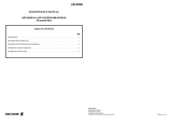
ericssonzLBI-39208Ericsson Inc.Private Radio Systems Mountain View RoadLynchburg, Virginia 245021-800-592-7711 (Outside USA, 804-592-7711)Printed in U.S.A.MAINTENANCE MANUAL GPS SIMULCAST SYSTEM DRA WINGS(Transmit Site)DESCRIPTIONThis maintenance manual provides GPS Simulcast System drawings used at the transmit site. These drawing include Transmit Site Configuration, Floor Plan, Interrack Cabling and an Interrack Cabling List. Transmit Site Configuration Draw-ing 19C852716, Sheets 1 & 2 show the configuration for a 24channel GPS Simulcast transmit site. Floor Plan Drawing 19C852721 shows the equipment layout for and the ductwork layout for the same configuration. Interrack Cabling Drawing 19C852722, sheets 1 & 2 shows the interrack cabling for a 24channel transmit site. Cable list 350A1888, Sheets 1-3 pro-vides a list of the GPS Simulcast Transmit Site Interrack ca-bling. This list also provides a wiring diagram (Figure 1) for the alarm cables connected from T801 (ALM OUT) to T813“A” (ALM IN), and from D801 (ALM OUT) to T803-A (ALM IN) and from D801 (ALM OUT) to T813_A (ALM IN). T801is GPS receiver “A” and T803 is 10 MHz Oscillator Selector &Distribution Amplifier #1. These two items are located in the Simulcast equipment rack. T813 is 10 MHz Oscillator Selector & Distribution Amplifier #2 located in a station equipment rack. D801 is GPS receiver “A” located in the common equip-ment rack at the Control Point. This cable is used only when the Control Point and the Transmit Site are co-located.Copyright© November 1996, Ericsson Inc.TRANSMIT SITE FLOOR PLAN This manual is published by Ericsson Inc., without any warranty. Improvements and changes to this manual necessitated by typographical errors, inaccuracies of current information, or improvements to programs and/or equipment, may be made by Ericsson Inc., at any time and without notice. Such changes will be incorporated into new editions of this manual. No part of this manual may be reproduced or transmitted in any form or by any means, electronic or mechanical, including photocopying and recording, for any purpose, without the express written permission of Ericsson Inc.EQUIPMENT LAYOUTDUCTWORK LAYOUTTransmit Site Floor Plan(19C852721, Rev. 1)LBI-392081LBI-39208TRANSMIT SITE CONFIGURATION DIAGRAM24 ChannelTransmit Site Configuration Diagram(19C852716, Sh. 1, Rev. 1)2LBI-39208 TRANSMIT SITE CONFIGURATION DIAGRAM24 ChannelTransmit Site Configuration Diagram(19C852716, Sh. 2, Rev. 1)3LBI-39208INTERRACK CABLING DIAGRAMInterrack Cabling Diagram(19C852722, Sh. 1, Rev. 0)4LBI-39208 INTERRACK CABLING DIAGRAMInterrack Cabling Diagram(19C852722, Sh. 2, Rev. 0)5INTERRACK CABLING LISTInterrack Cabling List(350A1888, Sh. 1, Rev. 1A)(350A1888, Sh. 2, Rev. 1A)83 CABINETSLBI-392086INTERRACK CABLING LISTInterrack Cabling List(350A1888, Sh. 3, Rev. 1A)REMOTE TRANSMIT SITE ONLYLENGTH TO BE DETERMINED ON SITET803/T813A L A R M INPUT8 PIN CONNECTOR(SUPPLIED WITH T803/T813)13 PIN CONNECTOR (SUPPLIED WITH T801/D801)T801/D801A L A R M O U T P U TFigure 1 - Cable*Requires DB-9 ’T’ AdapterCO-LOCATED TRANSMIT SDITE ONLY LBI-392087。
Compumotor Z635 电机用户指南说明书

U S E R G U I D E C H A N G E S U M M A RYThe following is a summary of the primary changes to this user guide sincethe last version was released. This user guide, version 88-010759-01H,supersedes version 88-010759-01G.The entire user guide has been changed according to the new Compumotoruser guide styles, format, and illustration standards. Also, the chapters havebeen renumbered and reorganized. Technical changes to each chapter aresummarized below.ChapterIntroductionThe Z635 motor was added to the “What You Should Have” section.ChapterGetting StartedChapter was unchanged.Chapter Installation t Installation (wiring) directions were provided for the Brake (-B) Braking option. t Maximum step rate was corrected (was 2.5 MHz, changed to 1 MHz). See STEP Input.t The DIRECTION Input schematic was modified.ChapterApplicationDesignChapter was unchanged.ChapterZ Series Shunt Regulator The capacitor energy absorption calculation was modified (refer to “Selecting a Z Series Shunt Regulator.”)Chapter Software Reference In the CTC command description, time increments were corrected from ms to µs.Chapter Hardware Reference An exception for Z600 and Z900 Series motors was added regarding the IP Classification. The shaft is IP30 rated (not IP65).ChapterMaintenance &TroubleshootingChapter was unchanged.T A B L E O F C O N T E N T S How To Use This User Guide (iii)Assumptions (iii)Installation Process Overview (iii)Installation Procedures (iii)Contents of This User Guide (iii)Related Publications (iv)À INTRODUCTION (1)Product Description (1)Product Features (2)Interface Options (2)Theory of Operation (2)` GETTING STARTED (5)What You Should Have (5)Drive/Motor Configuration (5)Check-Out Procedure (6)Tools (6)Position Mode (11)Torque Mode (12)Velocity Mode (13)´ INSTALLATION (15)Environmental Considerations (15)Complete System Configurations (15)Drive Mounting (15)Panel Layout (17)Motor Mounting (17)System Wiring (29)Connections (29)Resolver Connections (31)Indexer Connections (31)Indexer Connector Outputs (34)I/O[1] Connections (35)I/O[2] Connections (39)Line Power Connections (39)Check-Out Procedure (41)ˆ APPLICATION DESIGN (43)Basic Servo Tuning Theory (43)Servo Tuning (46)47 Alphanumeric Display and Pushbuttons...........................................................................................Tuning in Different Modes of Operation (49)Position Mode (50)Torque Mode (50)Velocity Mode (51)Pseudo-Quadrature Outputs (53)55˜ Z SERIES SHUNT REGULATOR.....................................................................................................What Is A Shunt Regulator? (55)Shunt Regulator Installation (55)Selecting a Z Series Shunt Regulator (56)Contents i¯ SOFTWARE REFERENCE (61)Command Format Description (61)Command Identifier (61)Command name (61)Version (62)Characteristics (62)Attributes (63)Description (63)Example (63)Command List (64)Alphabetical Command List (65)˘ HARDWARE REFERENCE (85)Z600 Electrical Specifications (85)Input Power (85)Output Power (85)Z600 Motor/Drive Configuration (85)Z600 Technical Data (86)Positional Repeatability (86)Positional Accuracy (86)Motor/Drive Compatibility (86)Motor Brakes (86)Motor Data (86)Speed/Torque Curves (94)Z800 Electrical Specifications (96)Input Power (96)Output Power (96)Z800 Motor/Drive Configuration (96)Z800 Technical Data (96)Positional Repeatability (97)Positional Accuracy (97)Motor/Drive Compatibility (97)Motor Brakes (97)Motor Data (97)Speed/Torque Curves (104)Z900 Electrical Specifications (106)Input Power (106)Output Power (106)Z900 Motor/Drive Configuration (106)Z900 Technical Data (106)Positional Repeatability (107)Positional Accuracy (107)Motor Drive Compatibility (107)Motor Brakes (107)Motor Data (107)Speed/Torque Curves (112)113˙ MAINTENANCE & TROUBLESHOOTING.....................................................................................Motor Maintenance (113)Drive Maintenance (113)Troubleshooting (113)Diagnostic LEDs (114)Drive Warning (114)Drive Faults (115)RS-232C Problems (116)Returning The System (116)APPENDIX (117)Alphabetical Command List (117)INDEX (119)ii Z Drive User GuideHow To Use This User GuideThis user guide is designed to help you install, develop, and maintain yoursystem. Each chapter begins with a list of specific objectives that should bemet after you have read the chapter. This section should help you find anduse the information in this user guide.AssumptionsThis user guide assumes that the user has a fundamental understanding ofthe following information.t Basic electronic concepts (voltages, switches, current, etc.)t Basic motion control concepts (torque, velocity, distance, force, etc.) Installation Process OverviewTo ensure trouble-free operation, you should pay special attention to theenvironment in which the Z Drive equipment will operate. Environmentalconditions include the layout, mounting, and wiring and grounding practicesused. These recommendations are intended to help you easily and safelyintegrate the Z Drive into your facility.Installation ProceduresBefore you attempt to install this product, you should complete the followingsteps:Review this user guide. Become familiar with the user guide's contents so thatyou can quickly find the information you need.Develop a basic understanding of all system components, their functions, andinterrelationships.After you have read Chapter and clearly understand what must be done toproperly install the system, begin the installation process. Do not deviate fromthe sequence or installation methods provided.Before you customize your system, check all of the system functions andfeatures to ensure that you have completed the installation process correctly.The successful completion of these steps will prevent subsequentperformance problems and allow you to isolate and resolve any potentialsystem difficulties before they affect your system.Contents of This User GuideThis user guide contains the following information.Chapter : Introduction This chapter provides a description of the product and a brief account of its features.Chapter : Getting Started This chapter contains a detailed list of items you should have received with your Z Drive shipment. It will help you become familiar with the system and ensure that each component functions properly.Chapter : Installation This chapter provided instructions for you to properly mount the system and make all electrical and non-electrical connections. Upon completion of this chapter, your system should be completely installed and ready to perform basic operations.Chapter : Application Design This chapter provides additional information that will help you customize the system to meet your application's needs. Important application considerations are discussed. Sample applications are provided.Chapter : Software Reference This chapter describes the Z Drive's set-up commands. These commands allow you to set system parameters, tune the drive, and display drive status.Chapter : Z Series Shunt Regulator This chapter contains information on the shunt regulator option for the Z Drive. Installation instructions, dimensions, and selection criteria (400W version vs. 800W version) are included.Contents iiiChapter : Hardware Reference This chapter contains information on system specifications (dimensions and performance). This chapter may be used as a quick-reference tool for proper I/O connections.Chapter : Maintenance & Troubleshooting This chapter describes Compumotor's recommended system maintenance procedures. It also provides methods for isolating and resolving hardware and software problems. Diagnostic error codes are listed.Related PublicationsThe following publications may be helpful resources.Seyer, Martin. RS-232C Made Easy: Connecting Computers, Printers, Terminalsand Modems. Englewood Cliffs, New Jersey: Prentice Hall, Inc., 1984Current Parker Compumotor Motion Control CatalogManual for the IBM or IBM-compatible computer that you may use with the Z DriveSchram, Peter (editor). The National Electric Code Handbook (Third Edition).Quincy, MA: National Fire Protection Associationiv Z Drive User GuideC H A P T E RIntroduction The information in this chapter will enable you to:t Understand the product's basic functions, features, and theory of operation Product DescriptionThe Z Drive is a brushless servo system that includes a brushlessservomotor, a brushless resolver (for feedback), and a Digital SignalProcessor (DSP) based servo amplifier. Digital electronics simplify systemoperation and maintenance.The Z Drive can accept either a digital (Step and Direction) input or ananalog (±10V) input. You can configure the Z Drive to servo on commandedposition, velocity, or torque. The series offers maximum speeds of 7000 rpm,maximum continuous torques of 9000 oz-in, and maximum peak torques of18000 oz-in.The Z Drive uses two processors to achieve high-performance servo control.The first processor (DSP) compares the commanded inputs (position,velocity, or torque) to the resolver feedback, and then determines the propermotor currents to apply. The second processor handles all usercommunication, error checking, and additional I/O. All servo performanceparameters are stored in battery-backed RAM (random access memory).Z Drive systems can be installed and operated easily with minimal trainingin servo systems. Z Series motor/drives are supplied as packaged systemsthat are factory compensated for typical load and performancerequirements. In most applications, no adjustments will be required. Whenadjustments are required, changes to the drive can be made from twointerfaces—push-button adjustments or an RS-232C interface. Theseinterfaces provide access to all servo parameters simply and effectively.The Z Drive's power amplifier uses a bipolar 7 kHz pulse-width modulation(PWM) sinusoidal current control scheme. This type of amplifier improvesreliability, power regulation, and low-speed smoothness.Chapter Introduction1Product Featurest Brushless servo motort Brushless resolver feedbackt Speeds to 7000 rpmt Torques to 9000 oz-in continuous (18000 oz-in peak)t User programmable resolutions (200 - 65536 steps/rev, 5000 steps/rev standard)t Multi-processor control: no drift, no analog pots to adjustt Fan-cooled compact drive enclosuret7 kHz PWM switching frequencyt Accepts digital step and direction inputst Accepts analog (±10V) input for velocity or torque controlt Analog (±10V) output monitor for either velocity or torquet Pseudo 4096 pulse per revolution (ppr) incremental encoder output forinterfacing with servo controlst Servo parameters factory-set and stored in battery-backed RAM (random accessmemory)t High-noise immunity due to optical isolation and brushless resolver technologyt Simple push-button adjustment of servo gainst Alphanumeric display for fault or user-defined messagest RS-232C interfaceInterface OptionsIn Step and Direction mode, the Z Drive is compatible with all Compumotorindexers. The Z Drive moves the motor one increment in the specifieddirection for each step pulse received. Both of the drive's Step and Directioninputs are optically isolated and can be driven by an external pulsegenerator. The Z Drive's resolution is programmable, so you can specifyconvenient motor increments. The optically isolated analog input accepts a±10V signal that may be configured as either a velocity or torque command.The ZX is the drive/indexer version of the Z Drive. It contains the servocontroller and a complete RS-232C based indexer that executesCompumotor's X Series programming language. You can combine motioncontrol parameters such as distance, velocity, and acceleration intosequences with time delays, loops, and programmable outputs. Thesesequences can be controlled via RS-232C or via external inputs that can beconnected to a PLC or host computer. You can use trigger inputs to coordinateprogram execution with external events. Multiple motion control programscan be stored in nonvolatile memory and executed automatically fromexternal sequence and trigger controls. The X Series language is based onsimple commands, and uses decimal numbers.Theory of OperationThe Z Drive's primary function is to servo to either a digital positioncommand from an indexer or to an analog voltage command (velocity ortorque) from a servo controller.In Position mode, the indexer sends a position command to the drive andthe resolver feeds back the actual position of the shaft. If the actual positionof the shaft is different from the commanded position, a positional error isproduced. The drive then commands torque to the motor to correct thepositional error. In Velocity mode, the servo controller sends a velocitycommand and the drive servos to it by comparing the commanded velocity tothe actual velocity. In Torque mode, the servo controller controls theactual shaft torque directly.2Z Drive User GuideChapter Introduction 3The Z Drive digital servo system is composed of three major components:the servo motor, the drive, and the resolver.Microprocessor-based IndexerSERVO MOTOR RESOLVERA Digital Signal Processor (DSP)Resolver - to -Digital Converter Digital-to-Analog Converter Communication (RS-232C, front panel, I/O)Z Drive Digital Servo SystemThe Z motor family consists of brushless, 3-phase, AC motors. The figure below illustrates the basic construction of the Z servo motor. The permanent magnets are securely held in place by metal bands and composite fiber materials to allow high-speed performance. The rotors are precision-balanced, which provides low- and high-speed smoothness. The windings are located in the outer portion of the motor (stator). This inside-outconstruction allows better heat dissipation than conventional brush-type motors. As a result, higher continuous torque and horsepower ratings are achieved for a given motor size.Stator LaminationStatorWindingsRotorMagnetsS4Z Drive User Guide Controlling the phase of each of the motor's stator currents ensures balanced 3-phase operation and minimizes torque ripple. Actual motor currents are sensed, and the current is adjusted using pulse width modulation. Feedback is provided by a single-speed, brushless, pancake-type resolver.The resolver is mounted directly to the motor shaft. This eliminates the need for internal coupling. The resolver stator windings are mounted to themotor housing.。
三横一竖定位灯

日成是一家专业从事光机电一体化产品的研究、开发、生产、销售;激光设备销售、电子技术、自动控制系统等产品高新技术企业。
公司经过多年发展,在光机电一体化的应用领域上,积累了丰富的研发及生产经验,形成了一套先进成熟的生产工艺。
其中,
鞋机定位灯可应用于制鞋机械的后踵定型机、前帮机、鞋面定型机,能起标示与定位作用,可提高操作人员的工作效率。
鞋机定位灯配用专用电源,具有很强的抗干扰性、高稳定性、抑制浪涌电流及缓启动等特点。
七横一竖灯特别适于恶劣的工作环境,能有效保证产品的稳定性和使用寿命。
我公司生产的同类产品还有:
鞋机定位灯、七横一竖定位灯、三横一竖定位灯、丰字定位灯、日成鞋机定位灯等
鞋机用镭射定位灯可应用于制鞋机械的后踵定型机、前帮机、鞋面定型机,能起标示与定位作用,可提高操作人员的工作效率。
鞋机用镭射定位灯为三横一竖+半弧投影灯、七横一竖投影灯,照出来线条明显清晰、光度柔和、不刺眼,使用寿命为8000小时以上。
型号:灯(RC635)+电源(RP040929)
波长:635nm;650nm
输出功率:5mw;10mw;50mw(可根据客户要求定做)
外型尺寸:多种,可根据客户要求定做
输出波段:可见激光器
工作介质:半导体激光器
激励方式:电激励式激光器
运转方式:连续激光器
光斑模式:丰字形;七横一竖
gl。
Christie DWU635-GS Christie DHD635-GS 产品说明
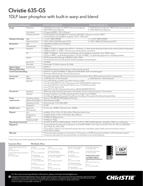
1DLP laser phosphor with built-in warp and blend
Technical specifications
Image
brightness
color wheel contrast (nominal)
Display technology Illumination Inputs
• Lens 0.75-0.95 Zoom G/GS • Lens 0.95-1.22 Zoom G/GS • Lens Zm Std G/599-GS 1.22-1.53 (Lowest cost for G/555/599/630-GS/635-GS) • Lens Zoom HP G/GS 1.22-1.52 (All G & GS) • Lens 1.52-2.89 Zoom G/GS • Lens 2.9-5.50:1 Zoom G/GS • Lens UST 0.36 (120") Ultra short throw lens, 630/635/700/850/1075-GS
• (LxWxH): 24.65 x 23.43 x 13.74" (626 x 596 x 349mm)
• 39.94lbs (15.85kg) w/o lens
• 47.06lbs (21.35kg)
• 32-104°F (0-40°C), 0-2500 ft altitude • 32-86°F (0-30°C), 5000-10,000 ft altitude • Humidity: 0-85% non-condensing
• Boresight adjustable • Motorized horizontal and vertical lens offset • Motorized zoom and focus adjustment
RDCU_4225说明书
ii
北京科锐配电自动化股份有限公司
RDCU-4225 微机站用变测控装置说明书
1
装置的适用范围
RDCU -4225 微机型站用变测控装置(低压)适用于变电站站用变的监控,实现站用变的“三遥”功能。 测量部分由电流测量、电压测量、频率测量、功率测量、功率因数测量组成。 监视部分有故障检测功能,过负荷告警、欠压告警、过压告警、装置故障告警等。 通讯部分由 485 总线组成监控网络,完成遥测、遥信、遥控、遥调及远方修改保护定值、远方信号复归
等功能。
2
装置的功能及特点
2.1 装置的主要特点
� 分散式系统 按每条线路对应于一个小机箱设计,装置可下放到开关柜上安装,也可集中组屏,各装置与通讯管理机 之间由 CAN 总线和 485 总线通迅电缆联络。装置分散配置,提高了系统的可靠性及可维护性,减少了 事故隐患。 � 硬件标准化 机箱只有四块小插件组成,电路原理简单、易于掌握。 � 先进高速的通讯网络 采用 CAN 和 485 双网配置,两网各有侧重,相互补充,既完成传统的通讯功能,又能实现变电站内的 保护配合、变位信息主动上报等功能。除此之外,每个装置还配置有 RS232 维护通讯口,为装置维护 提供了方便。 � 高可靠性 所有元件均采用工业级芯片,抗干扰能力强,故障率极低,独特的布线设计、电磁屏蔽、软硬件冗余、 脉冲群抑制使装置具有高抗干扰能力。 � 低功耗设计 装置电源交直流 220V 通用,电源功耗不大于 8W; � 开关量使用 DC 220V 电压输入 微机监控保护装置若使用 24V 作开入量电源,由于变电站强磁场干扰信号误报现象时有发生,本装置 直接使用直流 220V 作开入电源,即简化了接线又消除信号误报现象。 � 遥控投切保护、遥控复归信号 各保护功能可实现远方投切,各保护信号可实现远方复归。 � 开放式系统设计思想 可以和其它制造厂家的微机设备联网。 � 显示整定简单方便 显示为 LCD 汉字显示,人机界面友好,操作简便,显示内容丰富。
HM635卧加出厂指示书
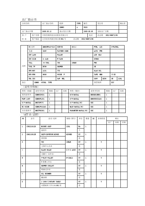
1
Y
内置旋转工作台0.001度
套
出厂指示书(B)〔出厂部品LIST〕
合同号码
出厂指示号码
机种
型号
编号
数控系统
发行者
CHM63
A
5020
OIMC
出厂指示日期
2009.05.12
发行日期
2009.05.05
实际出厂日
〔标准出厂品清单〕
NO
品号
品名/式样
规格
单位
数量
产地
机床本体
确认
出厂
未纳
后纳
1
ETRNF050000CNB
式样
NC式样
HM635F0iC-C10
NCR-NO
80414
PTRL LIG
3-PATROL
电源
380V
PATTERN CODE
AUTO PWR
CRT LANG
PALLET
AIR BLO
CRT SIZE
8.4LCD
W/TANK
STROK
TOLL
40 TOOL
TSC
20BAR
PMG
TOOL TP
BT50
ANCHOR
EA
16
F
锚
个
9
C40201024
COLLAR.FOUNDATION
S255285
EA
16
F
地脚轴环
个
10
C60021254
PLATE
EA
16
D
Y
垫板
个
11
R80013CN
KIT.TOOLபைடு நூலகம்BOX
L31900021
eco GMR635-2 说明书

Choosing a ChannelYour radio has 22 channels you can use to talk to others.In order to speak to someone, each of you must be set to the same channel.To choose a channel:With the radio in "Normal" operating mode press the ch/scan L or M key to increase or decrease the channel number displayed.Note:Channels 1-7 have an expectancy range of up to 6 miles.Channels 8-14 have an expectancy range of up to 2 miles.Channels 15-22 have an expectancy range of up to 6 miles.GMR635-2*Range may vary depending on environmental and/or topographical conditions.• 15 GMRS / 7 FRS Channels • Up to 6 Mile Range*• 5 Selectable Call Tone Alerts • Backlit LCD Display • Battery Recharge Circuit • Battery Level Meter • Channel Monitor • Channel Scan • Keypad Lock • Roger Beep • Key Beep1Antenna2PTT (Push-To-Talk) Button 3Monitor Key4Channel/Scan Up Key 5Channel/Scan Down Key 6Speaker7Call/Select Key 8Volume Up Key 9Power Key10Volume Down Key 11Microphone12Battery Level Meter 13Receive Indicator 14Scan Indicator 15Channel Indicator16Volume Setting Indicator 17GMRS/FRS Indicator 18Transmit Indicator 19Call Indicator20Keypad Lock IndicatorUSING THE RADIOIn order to get the most out of your new radio, read this reference guide completely before attempting to operate the unit.Turning the Radio On and Adjusting the Volume 1)key to turn the unit ON,the vol L key.To decrease the volume, press the vol M key.2)key again to turn the unit OFF .Adjusting the Sound (Key Beeps)Your radio emits a beep each time one of the buttons or keys (except for the PTT button and call/sel key) are pressed.To turn this sound OFF ,press and hold call/sel while turning ON the radio.Repeat this step to turn the sound ON.Navigating through the MenuTo access the advanced features of the GMR635-2,your radio has a Menu function.1)To enter the Menu, press and hold the call/sel key.2)Additional presses of the call/sel key will advance you through the Menu until exiting to "Normal" operating mode.3)Other methods of exiting the Menu function are:a.Press PTT , mon , or vol L /M .b.Wait 10 seconds until the unit automatically returns to “Normal ”mode.Talking on Your Radio To talk to others using the radio:1)Press and hold the PTT button and speak in a clear, normal voice about 2-3 inches away from the microphone.While you are transmitting, theicon will appear on the display.To avoid cutting off the first part of your transmission,pause slightly after pressing the PTT button before you start talking.2)When you are finished speaking, release the PTT button.Y ou can now receive incoming calls.While receiving, the icon will appear on the display.Transmitting a Call ToneYour GMR635-2 radio is equipped with 5 selectable call tones that will be transmitted when the call/sel key is pressed.To select a call tone:1)Enter the Menu.Advance through the Menu until the call icon is shown on the display.The current call tone number (-) will be indicated.2)Press the ch/scan L or M key to increase or decrease the number to the desired call tone.Each tone will be heard through the speaker.3)Exit the Menu.To transmit the selected call tone, press thecall/sel key.The selected tone will automatically be transmitted for a fixed length of time.Channel Scan FeatureYour GMR635-2 radio has a channel Scan feature that allows you to easily Scan all 22channels.When an active channel is detected, the unit will pause on that channel until the channel is clear.Then after a 2 second delay, the unit will continue scanning.Pressing PTT while the Scan is paused on a channel will allow you to transmit on that channel.To turn ON channel scanning:Press and hold either the ch/scan L or M key until the scan icon is displayed.The channel number on the display will change as the radio rapidly cycles through the channels.To turn OFF channel scanning:Press call/sel , or PTT .GMR635 RADIOKeypad Lock To Lock the keypad:1)Enter the Menu.Advance through the Menu until the icon appears on the display.The current key Lock status (OFF ) blinks on the display.2)To switch the key Lock mode from OFF to ON ,press the ch/scan L key.3)To confirm the setting, press the call/sel key.The radio returns to the "Normal" mode.Roger BeepRoger Beep is a BEEP that is sent to notify the end of transmission.Roger Beep can be heard through the speaker when Key Beep is on.Roger Beep is transmitted even if key beep is turned off.However Roger Beep will not be heard from the speaker.To turn OFF Roger Beep:Press and hold the ch/scan L key while turning ON the radio.To turn ON Roger Beep:Press and hold the ch/scan L key while turning the radio ON again.Channels15 GMRS / 7 FRS Operating Frequency UHF 462.5500-467.7125 MHzPower Source 4 AAA Alkaline Batteries(not included) or NiMHBattery Pack (not included) Range Channels 1-7 up to 6 milesChannels 8-14 up to 2 milesChannels 15-22 up to 6 miles Battery Life30 Hours typ.-Alkaline Batteries(5/5/90 duty cycle)18 Hours typ.- NiMHBattery PackFrequency ChartCh.Freq.Ch.Freq. 1462.562512467.6625 2462.587513467.6875 3462.612514467.7125 4462.637515 462.5500 5462.662516 462.5750 6462.687517 462.6000 7462.712518 462.6250 8467.562519 462.6500 9467.587520 462.6750 10467.612521 462.7000 11467.637522 462.7250Important:Evidence of original purchase isrequired for warranty service.WARRANTOR:UNIDEN AMERICACORPORATION ("Uniden")ELEMENTS OF WARRANTY:Uniden warrants, forone year, to the original retail owner, this UnidenProduct to be free from defects in materials andcraftsmanship with only the limitations or exclusionsset out below.WARRANTY DURATION:This warranty to theoriginal user shall terminate and be of no furthereffect 12 months after the date of original retailsale.The warranty is invalid if the Product is:(A) damaged or not maintained as reasonable ornecessary, (B) modified, altered, or used as partof any conversion kits, sub-assemblies, or anyconfigurations not sold by Uniden, (C) improperlyinstalled, (D) serviced or repaired by someoneother than an authorized Uniden service center fora defect or malfunction covered by this warranty,(E) used in any conjunction with equipment or partsor as part of any system not manufactured byUniden, or (F) installed or programmed by anyoneother than as detailed by the owner’s manual forthis product.STATEMENT OF REMEDY:In the event that theproduct does not conform to this warranty at anytime while this warranty is in effect, warrantor willeither, at its option, repair or replace the defectiveunit and return it to you without charge for parts,service, or any other cost (except shipping andhandling) incurred by warrantor or itsrepresentatives in connection with the performanceof this warranty.Warrantor, at its option, mayreplace the unit with a new or refurbished unit.THE LIMITED WARRANTY SET FORTH ABOVEIS THE SOLE AND ENTIRE WARRANTYPERTAINING TO THE PRODUCT AND IS IN LIEUOF AND EXCLUDES ALL OTHER WARRANTIESOF ANY NATURE WHATSOEVER, WHETHEREXPRESS, IMPLIED OR ARISING BYOPERATION OF LAW, INCLUDING, BUT NOTLIMITED TO ANY IMPLIED WARRANTIES OFMERCHANTABILITY OR FITNESS FOR APARTICULAR PURPOSE.THIS WARRANTY DOESNOT COVER OR PROVIDE FOR THEREIMBURSEMENT OVERPAYMENT OFINCIDENTAL OR CONSEQUENTIAL DAMAGES.Some states do not allow this exclusion or limitationof incidental or consequential damages so theabove limitation or exclusion may not apply to you.LEGAL REMEDIES:This warranty gives youspecific legal rights, and you may also have otherrights which vary from state to state.This warrantyis void outside the United States of America andCanada.PROCEDURE FOR OBTAINING PERFORMANCEOF WARRANTY:If, after following the instructionsin the owner’s manual you are certain that theProduct is defective, pack the Product carefully(preferably in its original packaging).The Productshould include all parts and accessories originallypackaged with the Product.Include evidence oforiginal purchase and a note describing the defectthat has caused you to return it.The Product shouldbe shipped freight prepaid, by traceable means, towarrantor:ONE YEAR LIMITED WARRANTYWARNING!It is up to the user to properlyoperate this radio transmitter to insure safeoperation.Please adhere to the following:Use only the supplied or an approved antenna.Unauthorized antennas, modifications, orattachments could impair call quality, damagethe radio, or result in violation of regulations.Do not use the radio with a damaged antenna.If a damaged antenna comes into contact withthe skin, a minor burn may result.Pleasecontact your local dealer for a replacementantenna.Body-worn OperationThis device was tested for typical body-wornoperations using the supplied belt-clip.To maintain compliance with RF exposurerequirements, Body-worn operations arerestricted to the supplied belt-clip.For hand-held operation, the radio should beheld 1 inch from the user's face.The use ofaccessories that do not satisfy theserequirements may not comply with RF exposurerequirements and should be avoided.RF EXPOSURE INFORMATIONCovered under one or more of the followingU.S.patents:4,684,8704,734,0495,203,0155,214,7895,491,7455,497,5085,517,6775,557,6065,574,9945,610,9465,613,2015,625,8705,627,8765,628,0595,634,1965,634,2055,678,1765,697,0965,717,3125,722,0705,787,3455,901,3416,021,3266,084,8616,163,6916,195,4156,353,730Uniden America CorporationParts and Service Division4700 Amon Carter Blvd., Fort Worth, TX 76155(800) 297-1023, 8 a.m.to 5 p.m.Central,Monday through Friday© 2004 Uniden America CorporationAll rights reserved Printed in ChinaUTZZ01915BZ。
映美 TP-635 打印机 说明书
-i-
TP-635 用户手册
目录
安全指导 ....................................................................................................................................................................I
第一章 产品特点 ................................................................................................................................................... 1
TP-635
TP-635 用户手册
安全指导பைடு நூலகம்
请在使用本产品前仔细阅读本手册,不要执行本手册中没有明确说明的操作。未经授权的操作会 导致错误或意外。制造商对因错误操作而导致打印机出现的任何问题均不负责。
Philips D635 Cordless Phone 说明书
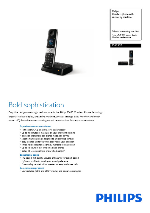
PhilipsCordless phone with answering machine30 min answering machine4.6 cm/1.8" TFT colour display Handset speakerphoneD6351BBold sophisticationExquisite design meets high performance in the Philips D635 Cordless Phone, featuring a large full-colour display, answering machine, privacy settings, baby monitor and much more. HQ-Sound ensures stunning sound reproduction for clear conversationsExperience true convenience•High contrast, 4.6 cm (1.8"), TFT colour display•Up to 30 minutes of messages on your answering machine •Black list, anonymous call, silence mode, call barring •Specific ringtone can be assigned to an identified contact •Baby monitor alerts you when baby needs your attention •Three-field entries for assigning 3 numbers to one contact •Up to 18 hours of talk time on a single charge •Caller ID – so you always know who is calling*Exceptional sound•HQ-Sound: high quality acoustic engineering for superb sound •MySound profiles to match your sound preference•Freestanding handset with a speaker for easy hands-free calls Eco-conscious product•Low radiation (ECO and ECO+ modes) and power consumptionHighlights4.6 cm (1.8") TFT colour display High contrast, 4.6 cm (1.8"), TFT colour displayBaby monitor functionReceive an alert when your baby needs you. Just place the DECT handset in the baby's room and receive an alert on your base or on another DECT phone (i.e. another landline number) or mobile phone (when you're out) when the baby starts to cry.Caller ID*Sometimes it's good to know who's calling before you answer. And our Caller ID lets you keep track of who's on the other end of the line.Eco-conscious model with ECO+Philips phones are energy efficient anddesigned to be respectful to the environment. When ECO mode is activated, the emitted radiation is reduced by up to 60%, and up to 95% when the phone is charging. With ECO+ mode activation, the radiation drops to zero.Extended privacy settings Black list restricts receiving calls from specific numbers or starting with certain digits, keeping unwanted calls away — you can block 4 sets of numbers. Anonymous call restricts incoming calls with hidden numbers, which aresometimes used by telemarketers. You can also set the phone to not ring so that you are not disturbed. With silence mode, you can disable the ringtone at specific times to enjoy peace and quiet. Thanks to call barring, you can avoid being surprised by expensive phone bills by blocking calls to specific numbers that start with certain digits (for example, pay-per-call numbers).Handset speakerphoneHands-free mode uses a built-in loudspeaker to amplify the voice of the caller, allowing you to speak and listen during a call without holding the phone to your ear. This is especially useful if you want to share the call with others or simply multitask.HQ-SoundPhilips cordless phones with HQ-Sound build upon decades of experience and breakthrough innovations in developing Hi-Fi audio products and high-end headphones to deliver excellent voice clarity on our DECT phones. When it comes to improving sound quality, our acoustics engineers and architects have thought of everything – high-qualitycomponents, digital signal processing, precise acoustic design, advanced testing and fine-tuning. The result is sound that is crisp, clear and authentic. Sound so good and natural, it is almost like being there in person.MySound profilesSound perception is subjective, and everyone has their own listening preference. MySound brings personality back to every conversation by allowing you to choose the audio profile that best matches your sound preferences: Clear—to make voices sound crisper and clearer; Soft—for friendly, softer tones;Warm—to make voices sound welcoming and warm.Issue date 2022-07-20 Version: 6.0.412 NC: 8670 001 27712 EAN: 48 95229 10322 1© 2022 Koninklijke Philips N.V.All Rights reserved.Specifications are subject to change without notice. Trademarks are the property of Koninklijke Philips N.V. or their respective owners.SpecificationsConvenience•Menu structure in the handset: Icon Menu •Speakerphone — talk hands-free •Personalisation: Silent mode•Call barring: Restrict the phone from making specific outgoing calls•Signal strength indicator: 3 bar indicator •Battery level indicator: 3 bar battery icon •Room monitoring•Date/Time display•Alarm Clock•Event light on the handset•Programmable hot keys: Keys 1 to 9•Call Management: Call Waiting*, Caller ID*, Microphone mute, Missed Calls, Received Calls, Dialled calls•Keypad lock•Key tone on/off•Auto Registration•Auto hang up•Number of keys: 22•Backlit keypad: White•Illuminated keypad•Enlarge dialling digit•Base Station keys: Paging key, Volume control, Answering machine keys•Up to 18 hrs talk time•Up to 250 hrs standby time•Charge time: 8 hours•Line cord length: 1.8 m•Power cord length: 1.8 m•Range: Open field <300 m; indoor <50 m •Family Notes•Block callers/Blacklist*: Restrict the phone from ringing on specific incoming numbers•Event notifications: for voice messages, missed calls and mute on•Non-slip grip: Ripple•Visual ringerSound•Sound Profile: MySound•Volume control on handset•Ringtones on handset: 10 Polyphonic / High-quality ringtones•HQ-SoundPicture/Display•Display size: 4.6 cm/1.8"•Display type: TFT colour 262K•Backlight:Yes•Backlight colour: WhiteAnswering Machine•Recording time capacity: up to 30 minutes•Pre-recorded OGM•Answering machine control: from base and handset•Loud speaker on base•Message indication on base: LED (Soft Amber)Memory Capacity•VIP Caller Identification•Phonebook: 100 names and numbers•Redial List Capacity: Last 20 numbers•Call log entries: 50 entries•Phonebook store in the base•Multiple phonebook entries: up to 3 numbersPower•Battery Capacity: 650 mAh•Battery type: AAA NiMH Rechargeable•Mains power: AC 100-240 V ~50/60 Hz•Power Consumption: <0.75 WSecurity•Transmission encryption: YesNetwork Features•Compatible:GAPSAR Value•Philips handsets: <0.1 W/kgEco Design•EcoMode: automatic and manual•Eco+Packaging dimensions•Packaging type: Carton•Number of products included: 1•Type of shelf placement: Laying•Packaging dimensions (W x H x D):18.4 x 13.5 x 5.9 cm•Gross weight: 0.4105 kg•Net weight: 0.333 kg•Tare weight: 0.0775 kg•EAN: 48 95229 10322 1**This feature requires additional subscription to Caller ID service.Please check with your local network operator for details.。
Epson PowerLite L635SU 全高清 WUXGA 短焦激光投影仪说明书

BusinessSPECIFICATION SHEETSpecification Sheet | Page 1 of 2PowerLite ®L635SU Full HD WUXGA Short-throw Laser ProjectorDisplay captivating signage from a short distance with this bright short-throw projector.3-Chip 3LCD image quality — with up to 6,000 lumens of equal Color and White Brightness 1 for vibrant, rich colorFull HD WUXGA support — native WUXGA 1920 x 1200 resolution for true-to-life images; accepts 4K signalBreakthrough laser technology — features a virtually maintenance-free 20,000-hour laser light source 2Project up to 200" from a single projector — or seamlessly join accurately color-matched images from multiple projectors; use split screen 3 for side-by-side projection from multiple inputs at the same time; Epson Projector Professional Tool Software compatibleSimplified installation — horizontal and vertical lens shift; geometric correction tools such as point, arc correction, built-in edge blending, Quick Corner ® and 360-degree flexibility make installation easyEasily programmable with the built-in media-player and content creation app 4 — which includes templates, effects, color filters and customizable options; playlist and playback function allows for seamless content management directly or via the networkCustom brightness and constant brightness modes — to maximize light source life and provide a consistent brightness levelRemarkable sharpness and detail — with up to 2,500,000:1 dynamic contrast ratio/laserprojectorsSpecification Sheet | Page 2 of 2Epson America, Inc.3131 Katella Ave., Los Alamitos, CA 90720Epson Canada Limited185 Renfrew Drive, Markham, Ontario L3R 6G3 www.epson.caEPSON, EasyMP , PowerLite and Quick Corner are registered trademarks, EPSON Exceed Your Vision is a registered logomark and Better Products for a Better Future is a trademark of Seiko Epson Corporation. PrivateLine is a registered trademark, and Epson Connection is a service mark of Epson America, Inc. Miracast ® is a registered trademark of Wi-Fi Alliance. All other product and brand names are trademarks and/or registered trademarks of their respective companies. Epson disclaims any and all rights in these marks. Copyright 2021 Epson America, Inc. CPD-60908 5/211 Color brightness (color light output) and white brightness (white light output) will vary depending on usage conditions. Color light output measured in accordance with IDMS 15.4; white light output measured in accordance with ISO 21118. |2 No required maintenance for the light source for up to 20,000 hours. Approximate time until brightness decreases 50% from first usage. Measured by acceleration test assuming use of 0.04 - 0.20 mg/m3 of particulate matter. Time varies depending on usage conditions and environment. Replacement of parts other than the light source may be required in a shorter period. | 3 Split Screen feature requires remote control. Consult your user manual for input combinations. |4 Internet connection required for download. Data usage fee may apply. |5 For convenient and reasonable recycling options, visit /recycle |6 SmartWay is an innovative partnership of theU.S. Environmental Protection Agency that reduces greenhouse gases and other air pollutants and improves fuel efficiency. | 7 Expedited shipping not available in all areas. Road Service orders must be in by 3 p.m. Eastern Time for Next-Business-Day delivery./laserprojectorsContact:Lens Shift Vertical: ±50%; horizontal: ±20%Keystone Correction Vertical: ±30 degrees; horizontal: ±30 degreesIllumination Technology Laser DiodeLight Source Life 2 Normal: 20,000 hours; Quiet: 20,000 hours; Extended: 30,000 hoursProjection LensType Optical Zoom (Manual)/Focus (Manual)F-number 1.7Focal Length 11.76 mmZoom Ratio Optical zoom 1 – 1.35x Throw Ratio Range 0.85 – 1.07Lens Cover Lens cap (without string)Wireless SpecificationsFrequency Type (Modulations) 802.11b/g/n (2.4GHz)Supported Security Type Quick Mode: OPEN, WPA2-PSK; Advanced Mode: WPA2/WPA3-PSK, WPA2/WPA3-EAPOther FeaturesOperating Temperature 32 ˚ to 113 ˚F (0 ˚ to 45 ˚C)Power Supply Voltage 100 – 240 V ±10%, 50/60 Hz AC Power Consumption 358 W (Normal Mode)267 W (Quiet and Extended)2.0 W Standby (Communication on)0.3 W Standby (Communication off)Fan Noise 38 dB (Normal Mode); max. 27 dB (ECO Mode)Security Security cable hole, Kensington lock provision A/V Mute YesSpeaker(s) 10 W (mono)Screen Mirroring Yes Split Screen YesContent Playback Yes Quick Corner Yes Arc Correction Yes Edge Blending Yes Screen Sharing YesHorizontal 15 kHz – 92 kHz Vertical 50 Hz – 85 HzEffective Scanning Frequency Range (Digital)Pixel Clock 13.5 MHz to 297 MHz Horizontal 15 kHz to 135 kHzVertical 23.98 / 24 / 25 / 29.97 / 30 / 50 / 59.94 / 60 HzDimensions (W x D x H)Excluding Feet 17.32" x 11.97" x 4.80"Including Feet 17.32" x 12.59" x 5.35"Weight 18.5 lbRemote ControlFeatures Power, source search selection, test pattern selection, A/V mute, freeze, user ID, auto, aspect, color mode, number, page up and down, E-zoom, volume, help, menu, enter, esc and pointer functionsOperating Angle Front Right/Left ±60 degrees; Upper/Lower: +30 to -20 degreesOperating Angle Rear Right/Left ±30 degrees; Upper/Lower: +50 to +10 degrees Operating Distance 26 ftEco FeaturesRoHS compliant Recyclable product 5Epson America, Inc. is a SmartWay ® Transport Partner 6Pre-sales support U.S. and Canada 800-463-7766Internet website Service ProgramsThe projector has a limited warranty of 3 years. Epson Road Service program with free Next-Business-Day replacement 7, PrivateLine ® dedicated toll-free support (U.S. and Canada only)What’s in the BoxPowerLite L635SU projector, power cable, computer cable (HDMI), projector remote control with batteries, Quick Setup Sheet, cable cover and Quick Setup posterOrdering InformationPowerLite L635SU V11HA29120Replacement air filter (ELPAF56) V13H134A56Ceiling Mount (Universal) ELPMBPJG V12H808001Custom Micro-Adjustable Projector Mount(ELPMBPRH) V12H809001HDBaseT transmitter (ELPHD01) V12H547020Wireless LAN module (ELPAP11) V12H005A02External Speaker (ELPSP02)Document Camera DC-07, DC-13, DC-211-year extended service plan EPPEXPE12-year extended service plan EPPEXPE2。
BRD633矿用微机保护测控装置说明书

BRD633矿用微机保护测控装置技术说明书北京北瑞达电力自动化设备有限公司BEIJING BEIRUIDA ELECTRIC POWER AUTOMATIC EQUIPMENT LIMITED COMPANY目录1产品综述 (1)2产品特点 (1)2.1 大资源高起点 (1)2.2 高可靠性 (2)2.3 一体化的设计 (2)2.4 易操作性 (2)3技术指标 (2)3.1 工作环境要求 (2)3.2 额定电气参数 (2)3.3 装置过载能力 (2)3.4 功率消耗 (3)3.5 主要保护功能配置 (3)3.6 主要测控功能 (3)3.7 主要的保护功能 (3)3.8 保护功能解释 (4)4装置硬件 (4)4.1 机箱结构 (4)4.2 交流输入部分 (5)4.3 CPU中央处理部分 (5)4.4 开关量输入及输出部分 (5)4.5 电源插件部分 (5)4.6 人机对话附件 (5)4.7 后备电源部分 (5)4.8 电池备用电源部分 (6)5保护原理 (6)5.1 三段式相间电流保护 (6)5.2 三段式零序过流保护 (6)5.3 过电压保护 (7)5.4 反时限过流保护 (8)5.5 低电压保护 (8)5.6 PT断线 (8)5.7 绝缘监视保护 (9)6人机对话操作说明 (9)6.1 人机对话简介 (9)6.2 主菜单说明 (11)6.3 实时数据 (11)6.4 事件记录 (12)6.5 定值管理 (12)6.5.1 运行参数 (13)6.5.2 速断 (14)6.5.3 过流Ⅰ段 (15)6.5.4 过流Ⅱ段 (15)6.5.5 PT断线 (16)6.5.6 反时限过负荷保护 (16)6.5.7 零序过流Ⅰ段保护 (17)6.5.8 零序过流Ⅱ段保护 (18)6.5.9 零序过流Ⅲ段保护 (18)6.5.10 过压保护 (19)6.5.11 失压保护 (19)6.5.12 零序过压保护 (20)6.5.13 低周保护 (20)6.5.14 绝缘电阻监察保护 (21)6.5.15 风电瓦斯闭锁 (21)6.5.16 不平衡电压保护 (22)6.5.17 功率方向 (22)6.5.18 故障模拟实验 (22)6.5.19 定值固化 (23)6.6 系统管理 (23)6.6.1 地址参数 (23)6.6.2 密码修改 (24)6.6.3 时间设置 (25)6.6.4 系数参数 (25)6.6.5 校正参数 (25)6.6.6 电度预置 (26)6.7 开关控制 (27)6.8 信号复归 (27)7故障分析 (28)8用户安装调试、维护说明 (28)8.1 注意事项 (28)8.2 装置的安装示意图 (29)8.3 定货须知 (29)9机箱外部端子定义 (30)10原理接线图 (31)10.1 弹簧储能机构原理图 (31)10.2 永磁机构原理图 (32)11装置外形及安装尺寸图 (33)1产品综述BRD633型矿用微机监控保护装置,适用于煤矿井下6~10KV电压等级的中性点不接地或中性点经消弧线圈接地的系统,保护装置集保护、监测、控制、录波、通信于一体,对井下的高压线路起到监控和保护作用。
德森印刷机说明书说课讲解
此文档收集于网络,如有侵权请联系网站删除目 录目 录 目 录第一章 系统描述.....................................................................3 1.1 功能特性........................................................................3 1.2 技术参数........................................................................4 1.3 外形尺寸........................................................................5 1.4 系统主要组成部分............................................................6 1.5 工作原理........................................................................7 第二章 设备安装与调试............................................................8 2.1 开箱..............................................................................8 2.2 操作环境........................................................................9 2.3 设备安置及高度调整.........................................................9 2.4 电源气源........................................................................9 2.5 工控机控制系统安装.........................................................9 2.6 软件安装........................................................................10 2 .6.1 软件功能简介......................................................... 10 2 .6.2 软件安装............................................................... 10 第三章 生产工作流程............................................................ 12 3.1 开机前检查.....................................................................12 3.2 开始生产前准备...............................................................12 3.2.1范本的准备...............................................................12 3.2.2 锡膏准备............................................................... 13 3.2.3 PCB 定位调试......................................................... 13 3.2.4 刮刀的安装............................................................ 14 3.2.5 刮刀压力和速度的选择............................................. 14 3.2.6 脱模速度和脱模长度................................................15 3.3试生产...........................................................................15 3.4生产流程图.....................................................................16 第四章 操作系统说明............................................................ 17 4.1 系统启动........................................................................17 4.2 主窗口组成 (17)4.2.1归零操作 (17)4.2.2主菜单栏 (19)此文档收集于网络,如有侵权请联系网站删除4.2.3主工具栏 (20)4.3 系统退出 (20)4.4 主菜单使用说明 (20)4.4.1打开 (20)4.4.2保存 (21)4.4.3 I/O检测 (21)4.4.4移动检测 (22)4.4.5过板 (23)4.4.6报警复位 (23)4.4.7联机 (23)4.4.8产量清零 (23)4.4.9刮刀移动 (23)4.4.10机器参数 (24)4.4.11更新有效期 (24)4.4.12系统密码 (24)4.4.13密码设置 (24)4.4.14语言 (24)4.4.15设置用户产品信息及生产信息 (24)4.4.16查看报警记录 (25)4.4.17生产记录 (25)4.4.18说明 (25)4.4.19故障查询 (26)4.4.20关于DESEN (26)4.5 主工具栏使用说明 (27)4.5.1资料录入 (27)4.5.2生产设置 (31)4.5.3网板自动清洗 (32)4.5.4开始生产 (32)4.5.5停止生产 (33)第一章系统描述此文档收集于网络,如有侵权请联系网站删除第一章系统描述1.1功能特性✪采用先进的图像视觉识别系统,独立控制与调节的照明,高速移动的镜头,精确地进行PCB与模板的对准,确保印刷精度为±0.025mm。