外文资料翻译---伺服阀试验台计算机辅助测试系统的研制
基于虚拟仪器2d伺服阀实验平台的研制
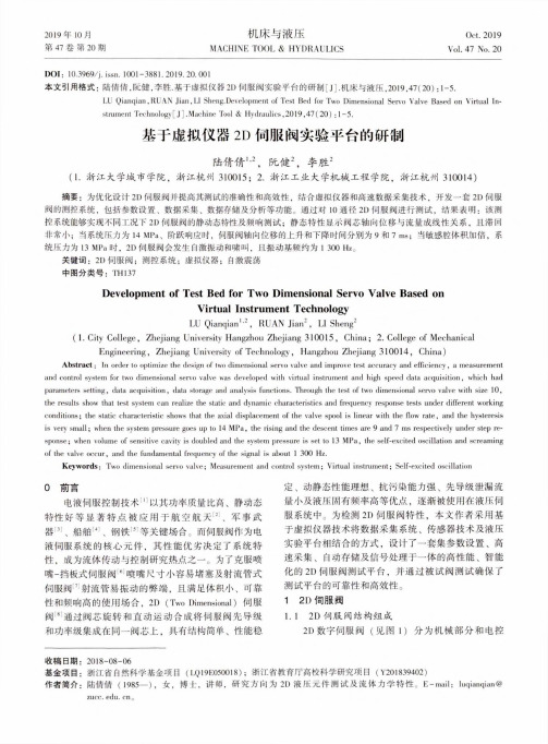
机床与液压MACHINE TOOL & HYDRAULICS2019年10月第47卷第20期Oct. 2019Vol. 47 No. 20DOI : 10.3969/j. issn. 1001-3881.2019.20.001本文引用格式:陆倩倩,阮健,李胜.基于虚拟仪器21)伺服阀实验平台的研制[J].机床与液压,2019,47(20):1-5.LU Qianqian, RUAN Jian, LI Sheng.Development of Test Bed for Two Dimensional Servo Valve Based on Virtual In strument Technology [ J ].Machine Tool & Hydraulics ,2019,47(20) : 1 -5.基于虚拟仪器2D 伺服阀实验平台的研制陆倩倩",阮健2,李胜$(1.浙江大学城市学院,浙江杭州310015; 2.浙江工业大学机械工程学院,浙江杭州310014)摘要:为优化设计2D 伺服阀并提高其测试的准确性和高效性,结合虚拟仪器和高速数据采集技术,开发一套2D 伺服 阀的测控系统,包括参数设置、数据采集、数据存储及分析等功能。
通过对10通径2D 伺服阀进行测试,结果表明:该测 控系统能够实现不同工况下2D 伺服阀的静动态特性及频响测试;静态特性显示阀芯轴向位移与流量成线性关系,且滞回非常小;当系统压力为14 MPa 、阶跃响应时,伺服阀轴向位移的上升和下降时间分别为9和7 ms ;当敏感腔体积加倍,系 统压力为13 MPa 时,2D 伺服阀会发生自激振动和啸叫,且振动基频约为1 300 Hz 。
关键词:2D 伺服阀;测控系统;虚拟仪器;自激震荡中图分类号:TH 137Development of Test Bed for Two Dimensional Servo Valve Based onVirtual Instrument TechnologyLU Qianqian 1'2, RUAN Jian 2, LI Sheng 2(1. City College , Zhejiang University Hangzhou Zhejiang 310015, China ; 2. College of Mechanical Engineering , Zhejiang University of Technology , Hangzhou Zhejiang 310014, China)Abstract : In order to optimize the design of two dimensional servo valve and improve test accuracy and efficiency , a measurementand control system for two dimensional servo valve was developed with virtual instrument and high speed data acquisition , which had parameters setting, data acquisition , data storage and analysis functions. Through the test of two dimensional servo valve with size 10, the results show that test system can realize the static and dynamic characteristics and frequency response tests under different working conditions ; the static characteristic shows that the axial displacement of the valve spool is linear with the flow rate , and the hysteresis is very small ; when the system pressure goes up to 14 MPa, the rising and the descent times are 9 and 7 ms respectively under step re sponse ;when volume of sensitive cavity is doubled and the system pressure is set to 13 MPa, the seK-excited oscillation and screamingof the valve occur, and the fundamental frequency of the signal is about 1 300 Hz.Keywords : Two dimensional servo valve ; Measurement and control system ; Virtual instrument ; Self-excited oscillation0前言电液伺服控制技术⑴以其功率质量比高、静动态 特性好等显著特点被应用于航空航天⑷、军事武器⑶、船舶⑷、钢铁⑸等关键场合。
毕业设计---伺服阀试验台设计
摘要随着液压工业的发展,液压技术在各种机械中发挥着越来越重要的作用。
由于液压系统的组成、功能日益复杂,因而发生故障的机率也随之增多。
液压缸的研究、设计、生产、使用与维修都离不开对其进行试验;设计一种能满足各种类型液压缸试验要求,并能以最少的资金和占用最小的场地解决实际问题的通用液压缸试验台已势在必行。
本课题在设计出的试验台液压原理图的基础上,借助先进的测量系统和经典的电气控制系统来实现液压缸的动静态特性测试。
其主要的测试项目的为液压缸的气密性、排量、容积效率、总效率等特性测试。
本课题所设计的液压缸动静态特性试验台最大压力达到31.5MPa,最大流量达到250L/min;能够满足缸径在200mm、行程在1500mm以下的液压缸的试验要求。
本系统的特点是:效率高、精度高、噪声小、泄露小、操作人性化等特点。
本系统还选用了一些先进的电子元件,系统稳定可靠、使用寿命长。
关键词液压技术,液压系统,液压缸试验台IABSTRACTWith the development of industrial hydraulic, hydraulic technology in the machinery to play an increasingly important role. As the hydraulic system of the composition, function increasingly complex and thus the failure rate also will increase. Cylinder research, design, production, use and maintenance can not be separated from its test; design a hydraulic cylinder to meet the test requirements of various types, and are able to at least the capital and occupied the smallest venue to solve practical problems Universal hydraulic cylinder test bed it is imperative.This topic in designs in the test platform hydraulic pressure schematic diagram's foundation, realizes the hydraulic cylinder with the aid of the advanced measurement system and the classics electric control system to move the static characteristic test. What its main test item is characteristic tests and so on hydraulic cylinder's gas tightness, displacement, volumetric efficiency, overall effectiveness index. The issue of hydraulic cylinders designed by static and dynamic properties of the greatest pressure reached to 31.5 MPa, the largest flow reached 250 L/min; able to meet bore in 200 mm, in 1500 mm trip following the test requirements of hydraulic cylinders. The system is characterized by: high efficiency, high precision, noise, leaking small, operating characteristics of human nature. The system also selected a number of advanced electronic components, the system is stable and reliable, long life.Keywords hydraulic technology,hydraulic system,hydraulic cylinder test bed绪论(标题1)1.1课题研究的背景(标题2)随着工业自动化水平的不断提高,利用计算机技术对工厂多渠道的信息进行管理以及对生产过程实施数据采集和监控,越来越受到人们的关注。
液压试验台计算机辅助测试系统
液压试验台计算机辅助测试系统
刘洋;吴兆迁;樊涛;曲振兴;牛晓华;王德柱
【期刊名称】《林业机械与木工设备》
【年(卷),期】2009(37)4
【摘要】对液压综合试验台辅助测试系统进行设计,给出了硬件和软件设计方案,实现了测试数据自动记录及处理功能.
【总页数】3页(P41-43)
【作者】刘洋;吴兆迁;樊涛;曲振兴;牛晓华;王德柱
【作者单位】国家林业局哈尔滨林业机械研究所,黑龙江,哈尔滨,150086;中国林业科学研究院新技术研究所,北京,100091;国家林业局哈尔滨林业机械研究所,黑龙江,哈尔滨,150086;中国林业科学研究院新技术研究所,北京,100091;国家林业局哈尔滨林业机械研究所,黑龙江,哈尔滨,150086;中国林业科学研究院新技术研究所,北京,100091;国家林业局哈尔滨林业机械研究所,黑龙江,哈尔滨,150086;国家林业局哈尔滨林业机械研究所,黑龙江,哈尔滨,150086;中国林业科学研究院新技术研究所,北京,100091;国家林业局哈尔滨林业机械研究所,黑龙江,哈尔滨,150086;中国林业科学研究院新技术研究所,北京,100091
【正文语种】中文
【中图分类】TP391.76
【相关文献】
1.QCS003液压试验台动态测试系统及其数据传输处理 [J], 严继东;杨志红;陈宏优
2.径向柱塞泵液压试验台虚拟仪器测试系统的研制 [J], 刘畅;杨淑敏;陈永会
3.液压试验台计算机辅助测试(CAT)系统的应用 [J], 陈菲;
4.计算机辅助实验测试系统研究 [J], 陈永海
5.基于虚拟仪器的液压试验台流量测试系统设计 [J], 郭艳珠;牛晓玲
因版权原因,仅展示原文概要,查看原文内容请购买。
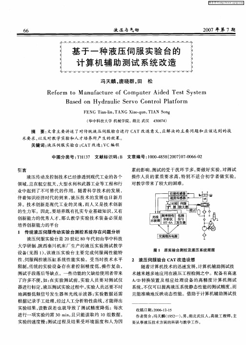
基于一种液压伺服实验台的计算机辅助测试系统改造
Ba e n Hy r u i e v n r lPlto m s d o d a l S r o Co to a f r c
FENG a —i TANG a — u TI Tin l n, Xi o q n, AN o S ng
( 中科技大学 机械学 院 , 华 湖北 武汉
成 , 助通 过 P 借 C机 的 VC编 程 , 用 不 同的 VC子 模 调 块 , 可 以构成 不 同的液 压传 动性 能测 试功 能 。“ 件 就 软 为灵魂 ” C 是 AT电液伺 服 阀控液 压缸 实验 台 的最 大特 点 。C AT软 件 系统采 用基 于模 块 化 的设 计 方 法 , 破 打 了传统 液 压测试 试验 台功能 不全 的现 状和 升级 困难 的
异 。技 术创 新是 现 代 工业 的灵 魂 , 而人 又 是 技 术 创 新
的生 力军 。因此 , 要培 养既 有扎 实专 业基 础知 识 , 又有 创新 能力 的优 秀人 才 , 么 教 学 实 验技 术 装 备 必 须 是 那 培养 创新 能力 的平 台
1 传统 液压 伺服 传 动实验 台测 控 系统存 在 问题分 析
维普资讯
液压 与气动
20 0 7年第 7期
冯天麟 , 唐晓群 , 田
松
Re o m o M a u a t r f Co p t r Ai e s y t m f r t n f c u e o m u e d d Te t S s e
收稿 日期 :0 61 .5 2 0 21 作者简介 : 冯天麟( 9 2 )男 , 15 一 , 湖北武汉 人 , 高级工程 师 , 主 要从事液压技术方 面的科研 与教学工作 。
维普资讯
20 0 7年 第 7期
伺服阀试验台计算机辅助测试系统的研制应用
2. 9 系统高压压力 表
3 . 制 2接 嘴 2控 3. 8 检测 1 嘴 接
3. 1 控制 2压 力 表 3 . 测 2接 嘴 4检 3 . 测 1 力表 7检 压 4 . 控 制 1接 嘴 O
3 . 测 2压 力 表 3检 3 . 统 低 压 接 嘴 6系 3 . 制 1压 力表 9控 4 . 服 阀 回 油接 嘴 2伺
伺服阀试验 台测试压力伺服阀及流量伺服阀的种
类 有 8项 。测 试 项 目包 括 : 载 流 量 特 性 曲线 ( 定 空 额 ( )夹具 中选 用抗腐 蚀 、 2 易清 洗 的钢作 为支 撑板 , 借助 钢板 的重 力在 高压 喷淋 下保 持稳定 。钢 板 开适 当
的孔 有 助于连 杆不 方便 冲洗 面在 涡 流下 冲洗 ;
中图分 类号 :H17 文献 标志 码 : 文章编 号 :0 04 5 (0 2 1 -0 20 T 3 B 1 0 -8 8 2 1 )00 6 -4
引盲
流量 、 偏 电流 、 环 、 性 度 、 成 度 ) 压 力 特 性 曲 零 滞 线 对 ;
伺服 阀试 验 台是为 飞机 大修 厂研 制 的测 试 电液 流
3. 5 系统 低 压 压 力 表
4 . 服 阀 回油 压 力 表 1伺
图 1 液 压 台 架 外 形 图
图 3 液 压 系统 工作 原 理 图
油温 冷却 机使 油 箱 油 液 外循 环 , 用 温度 自动 控 采 制 冷却 方式 满 足 系统工 作 液温度 要求 。 测 控柜 主 要 由仪表 显示 面板 、 示器 、 作按 钮 面 显 操
收稿 日期 : 1-32 2 20 -3 0
量伺服阀和电液压力伺服阀的设备。用于伺服阀性能 验收 、 机前 检查 、 装 定期 检查 及故 障检 测等 。该试 验 台 也适 用 于航 空修 理 厂 、 主机 厂 、 飞研 究 中心 、 服 阀 试 伺
【机械专业中文翻译】一种节能的液压疲劳试验机

机械专业中英文文献翻译外文翻译专业学生姓名班级学号指导教师外文资料名称:An Electric-power-savingHydraulic Fatigue-testingMachine 外文资料出处:Experimental Mechanics,2007,Volume 17, Number 1 ,Pages37-40附件: 1.外文资料翻译译文2.外文原文一种节能的液压疲劳试验机太田和佐佐木仓东路译摘要:液压疲劳试验机结合了机械液压波轮和闭环控制系统已经完成了实验。
对于电力和本机用水量约是伺服控制电液机的三分之一。
这种控制系统的稳定性在0.5%的范围之内。
实验结果鉴证了疲劳试验载荷下良好的稳定性。
简介:现在已经建成了具有三个环节的机械液压机。
它的稳定性在0.5个百分点范围内,电力消耗大约只有电动液压机的三分之一。
前言:液压和谐振式疲劳试验机用于高负荷疲劳试验中,谐振式疲劳试验机用少量的电力就可以运行,但它不能在一个高阻尼条件下,或长冲程和高负荷疲劳试验中运行,而液压机可以在这些条件下运行。
因此,液压疲劳试验机用于高负荷长冲程疲劳试验。
这种类型的机器通常分为两类:一类是伺服控制电动液压机,另一种是机械液压波轮。
伺服控制液压疲劳试验机具有闭环连续体系,并不断纠正了这个不同于负荷或伸长的命令信号。
因此,伺服控制电液压机可运行在一个负载或在有限频率的条件下,来延长任意波形。
也就是说,它不仅能产生正弦波形,也可以按照一个指令信号发生器产生任意波形。
然而,这种类型的机器需要大量的电力和水去冷却油液,所以它无论是在建设还是在营运上成本都很高。
如果实验室不具备足够大的电力供应系统,这种机器不能装备。
另一方面,波轮液压机确实比伺服控制的电液冷却机节约电力和用水。
不过,这台机器有一个开环控制系统。
也就是说,只要在开始对负荷幅值进行设置,这个值将不会自动改变。
此外,负载平均值保持在百分之五负载范围内,只能有一到两个油压开关,都是通过机械式波轮设备,带动气瓶阀开关的旋转的。
飞机液压伺服阀静态性能计算机辅助测试系统的设计
飞 机液压 伺 服 阀静 态性 能计算 机 辅助测 试 系统用
在计算机的控制下可实现为不同测试对象提供所需的 压力和流量 , 以满足 5 / i 的大流量输 出和2 P 0L rn a 5 a M
额定 压力 的测 试要求 。
2 过 相 应 的传 感 器 实 时跟 踪 采 集 管路 系统 的状态 参数 ( 压力 、 流量 、 液温 度 等 ) 被 测 油 、 产 品的性 能参数 , 并通 过屏 幕显示 , 同时将 状 态信息 提 供 给故 障诊断部 分进 行 分 析 , 测试 结 束 后 以报 表 形 式
关键 词 : 液压 系统 ; 液压伺 服 阀 ; 电液 比例 控 制
中 图分类 号 : H17 5 文献标 志码 : 文 章编 号 :0 04 5 (0 2 0 -0 90 T 3. B 1 0 -8 8 2 1 )60 4 -2
1 引 言
图 1所示 ) 。
液 压伺 服 阀是结 合 了机 械 、 子 和液 压 技 术 的 高 电 度精 密部件 , 在我 国主 战机 型 飞 机 液压 系统 中被 广 泛
图 1 测 试 系统 功 能 组 成 方 框 图
2 1 液 压 源 .
液 压源是 该测 试 系 统 的重 要 组 成 部分 之 一 , 功 其
阀的输入控制信 号, 人工读取数据 , 手动绘制试验 曲 线, 测试过程繁琐 、 测试效率低 、 测量精度低 , 很有必要
进 行测 试 自动化 的 改进 。“ 机 液压 伺 服 阀静 态 性 能 飞
提示信息得知检测设备本身的状态 ; 品 自动检测功 产 能, 通过 软件 控制 能 对被 测 产 品各 参 数 ( 性 、 力 特 极 压 性、 内漏 、 流量等参数 ) 进行 自动检测 ; 自保护功能, 为 避免故障件引起安全问题 , 导致设备损坏 , 在硬件和软 件上都设有保护 ; 监控功能 , 对检测全过程进行跟踪 ,
- 1、下载文档前请自行甄别文档内容的完整性,平台不提供额外的编辑、内容补充、找答案等附加服务。
- 2、"仅部分预览"的文档,不可在线预览部分如存在完整性等问题,可反馈申请退款(可完整预览的文档不适用该条件!)。
- 3、如文档侵犯您的权益,请联系客服反馈,我们会尽快为您处理(人工客服工作时间:9:00-18:30)。
Study on Computer Assistant Test System of ServoValve Test-bed Abstract:According to the need of the static and dynamic characteristics of the test on servo valve , firstly this article introduces the necessary part of the system-the pump station. Next, it designs the corresponding hydraulic an d computer-aided test system and given the composition of software and har dware of the test system and the design process of software.In the end,we a pply the designed system to actual production to prove that it achieve the r equirements of the test on servo valve.Key words:servo valve, test rig, CAT, dynamic and static characteristics1. IntroductionElectro-hydraulic servo valve is the frequently-used control component in measurement and control system. Due to the wide use of electro-hydraulic servo system in metallurgy, engineering machinery, and chemical industry, a large number of servo valves are also be applied in these industries.Affect by the facters of environmental,abrasion,aging and so on,servo valve will malfunction inevitably and need repairs after using a certain time.After maintenance and repair,we must detect the servo valve through some certain testing methods of dynamic and static to decide whether its various properties meet the stipulated requirements or not. Thus,large enterprises establish independent servo valve test-bed according to the own needs.What is described below is a servo valve test-bed developed jointly by our unit and a university and the test-bed is based on computer-aided testing.2.Hydraulic pump stationHydraulic pump station also known as the pump station is an independent hydraulic device. It offers oil according to the requirements gradually and controlls the direction, pressure and flow rate of hydraulic oil, applied to the mainframe and hydraulic devices separability of hydraulic machinery. After the purchase users just connect hydraulic station and host of implementing agencies (motor oil or fuel tanks) with tubing, and hydraulic machinery can be realize these movements and the work cycle.Hydraulic pump station consists of pump device, block or valve, tanks, a combination of electrical boxes.The function of each components are as follows:(1)Pump device is equipped with motors and pumps, is the source of power of the hydraulic station. It changes mechanical energy into hydraulic oil pressure energy.(2)Integration block is assembled by hydraulic valve and channel body. It can adjust the direction, pressure and flow of the hydraulic oil.(3)Valve portfolio plate valve is installed in the board and channels connect with each other after the board witch is the same as integration valve.(4)Tank plate is a welding semi-closed container, and also located with oil filtering network and air filters used for oil, oil filters and cooling.(5)Electrical boxes have two patterns. One designs external fuse terminal plate; The other installs a full range of electrical control.Hydraulic station principle: motor driven pump rotation, and pump absorbsoil from the oil tank and changes mechanical energy into hydraulic pressure energy of the station. Hydraulic oil through manifold (or valve combinations) realizes the adjusting of direction, pressure, flow .Then through external pipe to the cylinder hydraulic machinery or motor, so as to realize the changing of the direction , the size of the force and the velocity, to promote the machinery working of all kinds.3. Hydraulic testing system and testing methodsTest-bed can complete the test on static and dynamic characteristics of servo valve.Static characteristics of the test includes characteristics of unloaded flow, characteristics of pressure-gain, characteristics of flow-pressure and characteristics of leakage; dynamic characteristics are mainly the test on frequency characteristics of servo valve. The above testing results of characteristics need to be drawn out in the way of graph. Figure 1 is a schematic diagram of hydraulic test system.3456811121920211.percolator 2.hydraulic pump 3.overflowvalve 4.energy accumulator 516.turbineflowmeter6-91718.on-off valve 10.statictesting position of valve11.dynamic testingposition of valve 12-15.pressuretransducer19.dynamic cylinder 20.velocitytransducer21.displacementtrancducer22.proportional overflow valve23.check valve unit2716151417232218913AB P A B P10OFig.1 static and dynamic testing systemof electro-hydraulic servo valve 1OAccording to the testing tems ,we install the valve to be tested on the static and dynamic testing board respectively.When we execute a static test, we should close the switching valve 8, and open the valve 6 .On the contrary, turn on valve 8 , and turn down valve 6 when we do a dynamic test.3.1 Testing method of characteristics of unloaded flowOperations are as follows,when we test the characteristics of unloaded flow.First,close switch valve 18 and 7, and open valve 17 and 9.We should make sure the pressure difference between the two output ports A and B of the electro-hydraulic servo valve △PL=0. And then input triangle-wave current signal with the frequency of 0.01Hz into the valve being tested. The size of the current signal vary in accordance with the following rule: changes from 0 to +i max, then from +i max to 0, then to +i max , and back to 0.Turbine flow meter 16 detects the flow in the process of the varying current and input the computer with the measured flow and corresponding current.The computer can draw the curve of the flow varing with the current,namely the curve of the unloaded flow characteristics ± q = f (±i) △pL= 0. And according to the measured data ,we can calculate valve flow-gain, symmetry, zero-drift and hysteresis and other important properties of the valve.3.2 Test method of load-flow characteristicsThe operations of the test on load-flow characteristics are as follows: First, open switch valve 18 and 9, close the valves 17 and 7, make sure the oil of port A and B flows through the one-way valve 23 and proportional relief valve 22. Proportional relief valve (minimum moderating pressure <0.5MPa) can change the load pressure during the test,and the turbine flowmeter 16 can measure the flow under a variety of load operating conditions. To start the test,we should adjust the relief valve 3, make sure the pressure of the system is the same as the rated pressure of the electro-hydraulic servo valve to be tested.Then input the valve coilbeing tested with a triangle-wave current signal of 0.01Hz,and then control theproportional relief valve 22 to make the load pressure change gradually from zero to the rated pressure by a certain increment and measure the flow under each increment and input into the computer at the same time. And then change the amplitude of the input current (frequency unchanged), repeat the above process,we can measure curves of more groups.This is the characteristic curve of the load flow of electro-hydraulic servo valve ± q = f (±△ PL) i = Cont.3.3 Test method of pressure characteristicsBefore the test, closed switch valve 17,18 and 7 and open the valve 9, make sure the output flow of the valve to be tested is zero.Then adjust the pressure relief valve 3 so that the pressure of the system equals to the rated pressure and return oil pressure (measured by pressure sensor 13) . Then input the valve coil to be tested with a triangular wave current signal of 0.1Hz.The computer reads the value of pressure transducer 14 and 15,so we can detect the pressure difference of the two out port of the servo valve.Change the input current signal amplitude,and we can measure pressure value under different current amplitudes.Pressure-gain curves can be sketched out,according to the value of current and pressure difference ±△=f (± i) q =0.PL3.4 Testing method of leakage featuresClose switch valve 17,18 and 9,and open valve 7,then adjust the relief valve 3 to make the pressure of the system is the same as the rated pressure of the valve tobe tested.Then input the valve coil with exciting current and measure the flow by flow transducer 5,and input the computer with the leak signal and rated exciting current signal after sampling. Leckage curves can be sketched out by the testing system q r = f (± i) .3.5 Test of dynamic characteristicsAccording to the international standard , test of dynamic characteristics of current servo valve mainly refers to width of amplitude frequency when characteristic curve of amplitude frequency is -3dB and phase-frequency width when characteristic curve of phase-frequency is -90°.We should use 10 sinusoidal signals of different frequiencies for exciting signals of the valve coil to be tested ,then measure the output flow signal in turn and filter out the signals different with the exciting signal of the flow signal and serve it as the response signals of the servo valve to be tested . The two signals are entered into the computer by turns after sampling , and epuate the auto-spectral spectrum of the exciting signals G XX(f) and cross-power spectrum of exciting signals and responding signals G XY(f) . By this method we can get the frequency response H (f) = G XX (f) / G XY (f) .When we do the test of the dynamic characteristics , close switch valve 6 and open valve 8 . An independent signal generator produces scaning sinusoidal signal . The signal is entered into the servo amplifier after amplification and drive the dynamic cylinder to move . With the help of the speed sensor installed on the dynamic cylinder ,we can equate the output flow of the servo valve being tested .And the shift sensor installed on the other side can be used for preventing the dynamic cylinder from deviating from the central position .4. Current circuit of the test systemThe signals need to be collected during the static characteristics test of the testing system signals include Current signals of the servo valve coil to be tested, Pressure of inlet oil port , Pressure signal of load port A and B , Pressure signal of leaking mouth , Flow signal of load port A and B , Flow signal of leaking mouth . The signals need to be collected during the dynamic characteristics test include current signals of valve coil to be tested ,V oltage signal outputed by speed sensor 20.Control signals outputed by the testing system include setting value of pressure of the proportional relief valve , Stimulating signals of valve coil to be tested produced by signal generator .The amplify signals of the servo valve to be tested in the above signals are current signals and the others are voltage signal . As these signals detected by the sensor usually contain noise or through modulation . So the signals should go through corresponding treatment before being inputed into the computer , then converted into digital signals by A/D converter for further use .Separate digital signal generator is used during the test ,and the signal generator use single chip microcomputer16as its core and can produce triangle waves, sine waves, square waves, linear sweep sine wave signals with the frequency of 0~800H Z and so on for servo valve testing . Signal generator communicate with the main computer by RS232 . During the test , the maincomputer tell signal generator the parameters such as generative type of waveform , amplitude and frequency of waveform . Signal generator produce stipulated type of waveform and input it into the servo amplifier of the valve to be tested . During the test of dynamic characteristics , transport the produced waveform data into the mian computer at the same time for calculating dynamic characteristics . Circuit structure of the system is shown in Figure 2.current signal i ofvalve to be testedpressure signal 12,13,14,15flow signal 16 leakage flow signal 5 sinusoidal current signal of valve to be testedvelocity transducer 20signalinputchammelandconditioningdatecollectcardtestingsystemdigital signal generatorservo amplifier of valveto be testedsignaloutputchannelpressure settingdraw dynamiccharacteristics curvetest result documentand date conservation Fig.1 current signal of testing system5. Software of testing systemThe main function of the software system is to complete the disposition of measured data and draw the testing curve . So the system can be divided into signal processing module , data communication module , interface management moduleand auxiliary function modules responsible for test document processing and data storage . These modules also contain a number of sub-module respectively , and then sub-module call the function of basic library functions to complete their respective functions.Signal processing module is the most important module of the test system and its sub-modules include digital filtering, curve fitting , the difference, frequency response calculation and error compensation. Algorithms can be used by digital filtering conclude median filtering , correlation filtering , limited convergence filtering and so on . We can choose the appropriate filtering method according to field interfere circumstance . Least-squares principle is usually used in curve fitting to make error sum squares of curve points the minimum . Frequency response calculation includes the calculation of auto-correlation and cross-correlation calculation . The relevant calculation uses the fast Fourier transform and inverse transform to achieve fast correlation algorithm .Functions of communication module include read and write input/output data buffer, modules of communicate with each other of digital signal generator. Before the test , operator put needed pressure , channel of flow signal and waveform parameters of signal generator into the system .The system will call the buffer zone to establish the function and communicating functions to establish data buffering area of each channel and send parameters to the signal generator and start the D / A and A / D data conversion at the same time . Each channel using interrupt mode to write data into the buffer zone . CPU reads the data of each buffer zone at intervalsof 1s and call interface processing management module to refresh the output interface after date diaposition .Interface management module is mainly responsible for the drawing of static and dynamic characteristic curves.The process is completed by esch sub-module through calling Plot()function . Auxiliary function modules includes test data formatted output to a file, and test documents and data printing .The entire test system was developed under Microsoft VC6.0 , and its overall operation process is shown in Figure 3.PreparationMain InterfaceStatic DynamicStatic or dynamictest ?Choose static itemChoose test onpressure/flow/current Set paramater or pressure of signal generatorInput wrong ?Start D/ABuild buffer zoneDelay for 2sStart A/DRead dateDate filteringCurve fittingand differenceOver ?Stop date collect ,draw curveSave dateOverChoose current andspeed input channelSet scaning signalparamaterInput wrong ?Start D/ABuild buffer zoneDelay for 2sStart A/DRead dateDate filteringCalculateauto-correlationCalculate crosscorrelationCalculate frequencyresponse functionCurve fittingand differenceOver ?NoSave date ?NoYesNoYesYesYes Fig.3 testing software flow chat6. Examples for the testTable 1 is a experimental report generated by D072-386 servo valve produced by MOOG after repair . The main pilot project results and standard specifies were list in the report . Relate curves of the testing results are not enumerate here .Product 60L/min 12.5(mA)GB20233-882008/05/13MOD-D072-386S/N21321MPaA+,B- add 18mA biasing :C+,D-signal(2008) Servo check word No.(0001)±Table 1 electro-hudraulic servo valve test bed name electro-hydraulic servo valve Rated flow Rated input experiment dateTest standard Model and specification number components Rated pressure deliver sample unit maintenance unite connection modeXX thermal power plant XX hydraulic center01020304M L/min%Between A and B Between A and B200±8200>5010%>30±±81991995057.638OK OK OK OK OKTest resultsTest itemCoil impedanceInsulation Rated flow Pressure gain Measurementposition and unitDesignated valve After repair ,the measued value ConclusionRemarks7.ConclusionThe test system anlehnungs design methods of virtual instrument and bring function of software in the test into full play . The operation of the testing work is even more simple and intuitive with the maximum reduction in the use of hardware and save the cost of servo valve test-bed .伺服阀试验台计算机辅助测试系统的研制摘要:根据伺服阀的动静特性的测试要求,首先介绍了系统所需要的油源部分—液压泵站,然后设计了相应的液压测试系统和计算机辅助测试系统,说明了测试系统软硬件的组成和软件的设计流程,最后将设计出的系统应用到实际生产中,证明可以达到伺服阀的测试要求。
