ETS说明书
ETS1220说明书

安装电池 .....................................................3 安装 R- UIM 卡 ...........................................3 安装电源适配器 ..........................................3 安装室内天线 ..............................................4 连接固定台 .................................................4 查看接收信号强度.......................................5 安放固定台 .................................................6
4
连接固定台与电话机
固定台提供两个电话线口,分别是电话线口 1 和电话 线口 2,这两者在内部是直接互联的,可以任意选择 其中一个使用。
查看接收信号强度
2
安装说明
连接固定台与传真机
连接固定台与计算机
固定台与计算机连接,可以进行数据业务和维护调试 操作。具体信息,请咨询运营商。
说明 使用前,请确认您使用的固定台是否为支持传
安装室内天线
1 确定固定台关闭。
2 将室内天线如图所示的箭头方向,与固定台主机 的天线口对准,然后拧紧天线,确保天线和固定 台主机上的天线接口连接可靠。
连接固定台
说明
• 关闭固定台并断开电源适配器。
• 使用制造商提供的电缆。
• 固定台可以同时连接电话机和计算机,但电话 和数据业务不能同时操作,同一时间只能使用 一种业务。
ETS卫星中频光发说明书
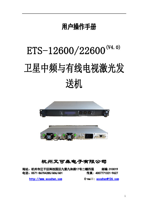
图(2 )
IF 1 OU T UT P OW ER 6. 1 4. 4m W
IF 1 LA S ER B IA S 6 .2 +1 20 mA
IF 1 LA S ER T EM P. 6. 3 25 .1℃
IF 1 LA SER C OO L . 6. 4 +0 31 2mA
IF 1 LA SER W AV E . 6. 5 1550.12 nM
备
注
详见规格
若偏离波长订货前要注明 SMSR
5
4 等效噪声强度 5 光调制方式 6 光输出功率 7 光反射损耗 8 光连接器形式
dB/Hz
dBm dB
CATV
1 2 3 4 5
6
7 8
频率范围 载噪比
平坦度
射频输入信号电平 载波组合三阶差拍 比(C/CTB) 载波组合二阶差拍 比(C/CSO) 射频输入阻抗
商标位置 状态指示灯
2、C AT V+ I F面板
SYS. NORMAL V4.0 00 H TT P: / /W WW .
LC D显示 窗口
2.2.2 后面板图
激光 输出 散热风扇
散热风扇
菜单上下键 选择键
菜单上下键 选择键
RF测 试口
电源输入
预留网管接口
IF输 入 激光输出 散热风扇 激光输出
散热风扇
可选-48VDC 单电源工作 全自动机箱温度控制
(W)x(D)x(H) 支持浏览器和 SNMP
6
SY S. INI T IA LI ZA TTI NG Wait... ...
SYS.NORMAL V4.0 0 HTTP//WWW.
MODEL
1
ETS系统使用说明书
ETS系统使用说明书1 概述上海汽轮机有限公司(STC)生产的这套危急遮断系统(ETS),为大型汽轮发电机组的运行配备了安全可靠的保护装置,当存在某种可能导致机组受损害的危险情况时,ETS装置可使汽轮机自动遮断,保护机组的安全。
ETS装置通过各传感器监测着汽轮机的运行情况(见图1、ETS 系统图)。
具体监测的参数为:汽机超速110%(OS)EH油压低(LP)润滑油压低(LBO)冷凝器真空度低(LV)推力轴承磨损(轴向位移RP)由用户决定的遥控遮断信号(RM)该装置还具有以下功能:各通道在线试验并不会导致汽轮机正常遮断误动或拒动。
任一元件出故障不会导致汽轮机因误动作而遮断。
任意某个元件故障时,仍可检测出有效的汽轮机遮断情况并能成功地遮断汽轮机。
该套ETS装置有一个控制柜和一块运行人员试验面板(图2,3,4),控制柜中有两排可编程逻辑控制器(PLC)组件,一个超速控制箱,其中有三个带处理和显示功能的转速继电器,一个交流电源箱,一个直流电源箱以及位于控制柜背面的二排输入输出端子(U1-U4)。
PLC组件是由两套独立的PLC组件组成:主PLC(MPLC)和辅助PLC(BPLC),这些PLC组件采用智能遮断逻辑,必要时提供准确的汽轮机遮断,每一组PLC均包括处理器卡(CPU)和I/O接口卡,CPU含有遮断逻辑,I/O接口组件提供接口功能,下面一排构成MPLC,提供全部遮断、报警和试验功能。
上面一排处理器为BPLC。
这是含有遮断功能的冗余的PLC单元;如果主PLC故障,它将允许机组继续运行并仍具有遮断功能。
而在MPLC正常运行时,ETS具有全部遮断、报警和试验功能。
三个转速继电器均能够将独立的磁阻发送器的输入信号进行数字处理,并且当转速超过继电器设定点时,继电器的触点闭合或断开。
在每个转速继电器中有二个转速设定点触发二个独立的继电器,并提供转速指示,S1为正常超速设定点,通常被设定为额定转速的110%(3300 R/MIN),S2定义提高的超速设定点,通常定义为额定转速的114%(3420 R/MIN)。
易科无线解决方案提供商 ETS1278R1825 V01 模块说明书
ETS1278R1825微功率模块说明书(18*25*2mm 射频前端)深圳易科软件有限公司Mb/VX:QQ:8246 8188https:// https://Email:Factory: 深圳市龙岗区坂田风门路52号金源科技园2栋305室版权声明:本产品为我司ODM产品,任何个人和公司都可以使用和宣传。
如有更好建议对本手册进行修改,请同时通知我们。
对应用产品有开发,设计需求和合作,请及时联络。
信任,合作,共赢!目录一、 模块介绍二、 产品特点三、 应用范围四、 尺寸与引脚定义五、 技术参数六、 模块应用注意事项七、 常见故障及排除方法八、 客户订制要求一、 模块介绍模块采用SX127x系列收发射频芯片,采用LORA扩频无线射频技术,数字处理技术,高抗干扰,高稳定性和高性价比。
用户只需通过模组提供的SPI数字接口,控制芯片内部寄存器,实现对SX127x 参数配置、无线数据收发等功能。
该模块具有尺寸小,灵敏度高,传输距离远,通讯速率高,延时小。
用户可以根据自己的要求来定制模块尺寸,输出功率,频率段等参数,或者直接将将模块布板到用户的PCB上,提升客户的产品水平和节省成本。
二、 产品特点微功率发射,最大输出20dbm,可通过设置控制发射功率。
工作频段:137MHZ-1020Mhz 等免申请频段,可根据用户的要求定制工作频段。
接收灵敏度最高达-148dBm@1200bps,在天线高度2米时,开阔地无干扰情况下可达3000米。
三、 应用范围无线排队设备,酒店电子门锁、生物识别门禁管理系统智能家居、家庭电器和灯光智能控制医疗和电子仪器仪表自动化控制智能教学设备、婴儿监护、医病房呼叫系统防盗报警,车辆防盗,智能卡,铁路机车远程检测水、电、煤气,暖气自动抄表收费系统或无功补偿及电网监测无线会议表决、打分系统,PDA终端、无线点菜系统LED屏无线传输文字,图片和无线控制,电子衡器、无线吊秤、车辆监测、老化设备检测,工业设备数据无线传输以及工业环境监测视频监控云台控制,门禁考勤读卡器气象/油井/水利设备信息采集以及自然环境检测资产管理和人员区域定位、物流供应链管理。
ETS使用手册PLC200
技术咨询直拨热线:0510-81631187
传真:0510-86328802
全国免费咨询电话:800-828-7883
邮编பைடு நூலகம்214413
网址:
E-mail:houde@
目录
第一章 总述 .................................................................................................................. 4
另有补汽阀试验按钮主电源副电源复位试验超速停机轴向位移大振动大润滑油压低真空低轴承回油轴承轴瓦温发电机保护deh保护备用1备用2温度高停机停机指示指示指示指示指示指示指示指示指示超速停机轴向位移振动大保护润滑油压低轴承回油温轴承轴瓦温发电机保护de保护备用1备用2保护保护保护度高保护度高保护停机停机超速停机轴向位移振动大保护轴承回油温轴承轴瓦温发电机保护de保护备用1备用2真空度高保护停机保护保护度高保护停机试验试验试验试验试验试验试验试验试验试验试验31操作盘面板示意图54停机指示当现场出现停机信号时且投切允许开关打到投状态首出信号对应的指示灯闪烁其他信号对应的指示灯亮
4.2 信号线的连接........................................................................................................................9
第五章 系统的使用 .................................................................................................... 10
ABB i-bus KNX 电能表接口模块 ETS 参数设置(A- B-系列)说明书
© ABB Mrz-14 STO/G | 29
B24
ZS/S 1.1 Meter Interface Module ETS Parameter settings B24 Steel
* * **
* freely adjustable ** NOTE:
Settings in ETS parameter Voltage network (4-wire or 3-wire) must be identical with voltage network settings in the meter.
© ABB Mrz-14 STO/G | 16
© ABB Mrz-14 STO/G | 17
A44
ZS/S 1.1 Meter Interface Module ETS Parameter settings A44 Steel
* * **
* freely adjustable ** NOTE:
Settings in ETS parameter Voltage network (4-wire or 3-wire) must be identical with voltage network settings in the meter.
© ABB Mrz-14 STO/G | 23
ZS/S 1.1 Meter Interface Module ETS Parameter settings B21 Silver
© ABB Mrz-14 STO/G | 24
© ABB Mrz-14 STO/G | 25
B23
ZS/S 1.1 Meter Interface Module ETS Parameter settings B23 Steel
ETS使用说明书(TS600MW)
1 系统概述上海汽轮机有限公司(STC)生产的这套危急遮断保护系统(ETS),为大型汽轮发电机组的运行配备了安全可靠的保护装置,当存在某种可能导致机组受损害的危险情况时,该套装置可使汽轮机自动遮断,保护机组的安全。
ETS装置通过各传感器监测着汽轮机的运行情况。
具体监测的参数为:•汽机超速110%(OS)•EH油压低(LP)•润滑油压低(LBO)•冷凝器真空度低(L V)•推力轴承磨损(轴向位移TBW)•由用户决定的遥控遮断信号(REM)该装置还具有以下功能:•各通道在线试验并不会导致汽轮机正常遮断误动或拒动。
•任一元件出故障不会导致汽轮机因误动作而遮断。
•任意某个元件故障时,仍可检测出有效的汽轮机遮断情况并能成功地遮断汽轮机。
该套ETS装置有一个控制柜,控制柜中有两套可编程逻辑控制器(PLC)组件,一个超速控制箱,其中有三个带处理和显示功能的转速继电器,一个交流电源箱,一个直流电源箱以及位于控制柜背面的二排输入输出端子(U1-U4)。
PLC组件是由两套独立的PLC组件组成:主PLC(MPLC)和辅助PLC(BPLC),这些PLC组件采用智能遮断逻辑,必要时提供准确的汽轮机遮断,每一组PLC均包括处理器卡(CPU)和I/O接口卡,CPU含有遮断逻辑,I/O接口组件提供接口功能,上面一排处理器构成MPLC,提供全部遮断、报警和试验功能。
下面一排处理器为BPLC,是含有全部遮断功能的冗余的PLC单元;如果主PLC故障,它仍继续运行并具有遮断功能。
三个转速继电器均能够将独立的磁阻发送器的输入信号进行数字处理,并且当转速超过继电器设定点时,继电器的触点断开。
在每个转速继电器中有二个转速设定点触发二个独立的继电器,并提供转速指示,SP1为正常超速设定点,通常被设定为额定转速的110%,SP2定义提高的超速设定点,通常设定为额定转速的114%。
三只磁阻传感器探头探测转速。
当PLC逻辑指示出三个转速继电器中有两台转速超出,PLC就发出超速信号遮断汽轮机,这样可以防止因一个传感器或转速继电器出故障,导致不当的汽轮机遮断或阻止正常的汽轮机遮断。
ETS系统功能说明书

ETS保护功能说明一、系统说明1.ETS系统由两套冗余的PLC系统组成,共用两路热备用控制电源。
2.PLCA和PLCB正常运行中同时工作,当任何一套故障时,另一套还可正常工作,有一路总的出口扩展继电器。
3.PLCA和PLCB在逻辑上完全相同,实现功能完全相同。
4.ETS保护切投开关只有一套硬开关,在ETS柜面板上,保护切投必须在ETS柜内实现,在DCS画面上有每个ETS保护切投状态指示。
5.ETS首出在DCS画面有显示,在ETS柜面板上也有两路首出指示灯,首出必须在ETS柜内复位。
二、逻辑说明1.在操作台手动同时按下停机按钮时,分两路停机:一路是进入ETS柜通过PLC出口停机;一路是进入DEH系统,再进入ETS柜通过PLC出口停机。
2.在汽机超速保护开关投入时,当TSI系统3个汽机超速探头中有任何2个转速大于3300rpm时,ETS保护动作,汽机跳闸。
3.在凝汽器真空低保护开关投入时,当凝汽器真空3个就地开关中有任何2个低于-66KPa时,ETS保护动作,汽机跳闸。
4.在润滑油压力低保护开关投入时,当润滑油压力3个就地开关中有任何2个低于0.0392MPa时,ETS保护动作,汽机跳闸。
5.在EH油压力低保护开关投入时,当EH油压力3个就地开关中有任何2个低于7.8MPa时,ETS保护动作,汽机跳闸。
6.在汽机轴向位移保护开关投入时,当TSI系统2个汽机轴向位移探头同时大于+1.2mm时,ETS保护动作,汽机跳闸。
7.在汽机轴向位移保护开关投入时,当TSI系统2个汽机轴向位移探头同时大于-1.65mm时,ETS保护动作,汽机跳闸。
8.在汽机轴振保护开关投入时,当TSI系统12个汽机轴振探头任何一个大于250um时,ETS保护动作,汽机跳闸。
9.在锅炉MFT保护开关投入时,当锅炉MFT继电器动作时,ETS保护动作,汽机跳闸。
10.在电气故障保护开关投入时,当电气故障时,ETS保护动作,汽机跳闸。
11.在DEH故障保护开关投入时,当DEH转速大于3300rpm时,ETS保护动作,汽机跳闸。
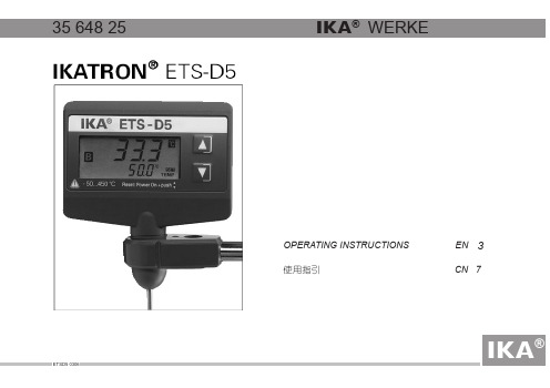
ETS-D5 3564825说明书
"s" key /"s"键 "t" key /"t"键
更换延长线和温度传感器
当磁力搅拌器开启时该温度计将开始工作。如果连接器上的 输入电压不是8V到16V的直流电源,需要改用H52电源供应设备 (H50双连接适配器和H51插入电源供应系统)。该电源供应系统
在更换温度传感器和延长线时,拔下传感器以及保护连接帽即 可。然后换上要用的传感器或者延长线以及保护性连接帽。
Er 5 传感器未置于溶液中(加热3分钟后屏幕显示溶液温度无 连接要求:
DIN 12 878 等级2
变化);
外形尺寸:
80 x 20 x 90 (不带传感器)
Er 6 传感器回路短路;
重量:
kg 0.2Kg
Er 7 当前温度超过设置的最高安全温度;
Er 8 校准误差(需重新校准)
配件
H38 H44 H50 H52 H62 H66 H70 AD-C1
控制偏差
K
±0.5
输入电压
V
直流 8...16
输入电流
mA 8mA(9V时)
环境温度
℃ 0...60
错误信息明细
相对湿度
%
80
工作制
%
100
以下为使用时可能出现的错误信息(如图5)及相应的出错原 保护等级
IP54
因:
ETS3(_操作说明书

ETS3 使 用 说 明1、操作界面介绍打开ETS3软件出现用户操作界面,如下图1-1所示:图1-1在“File ”文件菜单下的第一项“New Project ”新建工程项目,例如:新建项目“hager ”。
图1-2新建 打开 数据库产品 查询连接 设备信息 组监视 程序下载 总线监视新建项目后将出现用户操作界面,操作界面如图“图1-3”所示:图1-3ETS3操作界面主要分成3个工作区域:●“Topology”项目拓扑结构区:直观反应该项目的EIB总线拓扑结构。
●“Group”项目组地址区:总览及编辑项目中各设备所需的组地址。
●“Buildings”项目建筑结构区:反应项目建筑结构,主要用于编辑EIB设备的物理地址。
ETS3通过这三个工作区域可较明确的提供项目信息、主要的EIB设备配置、设备组地址及物理地址等,每个区域中可以让您轻松的使用和编辑对象。
1.1项目建筑结构区图1-41.1.1如何新建项目建筑结构要如何新建一个项目建筑结构并在所需的建筑添加相应的EIB设备呢?首先,选中“Buildings/Functions”建筑/功能项单击鼠标右键,选择“Add Buildings”增加建筑,例如增加一个名为“hager”的建筑物。
图1-5假设该项目的建筑物有三个房间,分别为“room 1”、“room 2”、“room3”,下面我们来增加一个名为“Room 1”的房间,选中“hager”单击鼠标右键,选择“Add Room”增加房间。
图1-6剩下的房间“room 2”和“room 3”请依照上述说明自行增加。
1.1.2导入EIB厂商产品数据库在增加EIB设备之前,您必须先将设备的产品库导入ETS3当中。
选中“File”文件菜1-7单下的“Import”,单击鼠标左键,如图依照下图1-8提示,导入EIB厂家提供的设备数据库:历史打开文件图1-8由于导入产品数据库过程所需时间较长,请各位耐心等待。
每个厂家的数据只需导入一遍即可,下一次新建项目或者是ETS3软件卸载重装时,该数据库仍然保留可用。
ETS说明书(600MW)

可门电厂危急遮断系统( ETS ) 使用说明书上海汽轮机有限公司2006年3月1.系统概述:上海汽轮机有限公司(STC)生产的危急遮断系统(ETS),根据汽轮机安全运行的要求,接受就地一次仪表或TSI二次仪表的停机信号,控制停机电磁阀,使汽轮机组紧急停机,保护汽轮机的安全。
危急遮断系统(ETS)对下列参数进行监视,一旦参数超越正常范围,通过停机电磁阀,使所有阀门油动机关闭。
ETS装置通过各传感器监测着汽轮机的运行情况(见图1、ETS系统图)。
具体监测的参数为:·汽机超速110%· EH油压低·润滑油压低·冷凝器真空度低·推力轴承磨损(轴向位移大)·由用户决定的遥控遮断信号ETS系统应用了双通道概念,允许重要信号进行在线试验,在线试验时仍具有保护功能。
2.系统组成:ETS系统由下列各部分组成:一个安装遮断电磁阀和状态压力开关的危急遮断控制块、四个安装压力开关和试验电磁阀的试验遮断块、三个转速传感器、一个装设电气和电子硬件的控制柜以及一个遥控试验操作面板。
汽轮机上各传感器传递电信号给遮断控制柜,在控制柜中,控制器逻辑决定何时遮断自动停机危急遮断总管的油路。
2.1 危急遮断控制块危急遮断控制块当自动停机遮断电磁阀(20/AST)励磁关闭时,自动停机危急遮断总管中的油压就建立。
为了进行试验,这些电磁阀被布置成双通道。
一个通道中的电磁阀失磁打开将使该通道遮断。
若要使自动停机遮断总管压力骤跌以关闭汽机的蒸汽进口阀门,二个通道必须都要遮断。
20/AST电磁阀是外导二级阀。
EH抗燃油压力作用于导阀活塞以关闭主阀。
每个通道的导阀压力由63/ASP压力开关监测,这个压力开关用来确定每个通道的遮断或复通状态,以及作为一个联锁,以防止当一个通道正在试验时同时再试另一个通道。
2.2 危急遮断试验块每个试验块组装件由一个钢制试验块、二个压力表、二个截止阀、二个电磁阀和三个针阀组成。
ETS系列智能扫描仪与台灯使用手册说明书

ETS系列产品使用手册目录第一章产品简介1.1产品概述 (2)1.2产品尺寸图 (2)1.3产品示意图 (3)1.4产品参数 (5)1.5包装及配件 (6)第二章操作指引2.1扫描仪模式 (6)2.2台灯模式 (8)第三章常见故障对策3.1扫描仪 (9)3.2台灯 (10)第四章服务与声明4.1售后服务与保证 (11)4.2联系方式 (12)第一章产品简介1.1 产品概述ETS是CZUR新推出的一款智能扫描仪,也是一款智能台灯,ETS采用MIPS CPU、高清传感器、U形光学、智能声控等高端配置,ETS不仅为用户呈现高清、绚丽的图像质量,同时为用户提供无辐射、低频闪、均匀光、多场景的台灯功能。
适用于教育领域、企业用户、专业人士、家庭及个人等,可扫描学习资料、书籍、试卷、文件、档案、表单、票据等。
扫描仪核心算法曲面展平、清除手指、智能分页、智能纠偏裁边、多种色彩模式优化等为用户展示丰富多彩的扫描效果,彻底改变了传统扫描仪、复印机的工作理念,展示了现代扫描仪的智能新概念,为用户呈现了一款智能、高效、节能的办公设备。
台灯支持自带旋钮控制及移动端App智能控制,有自然光、阅读书写、看电脑、智能夜间场景切换功能。
1.2 产品尺寸图25 7310 9 8说明:42、3、4、5分别是支架,底座,头壳,LED 节能灯,辅助安全激光灯高清 CMOS 镜头旋钮开关长按1S,开/关机短按切换台灯/扫描仪模式旋转调整灯光强度,逆时针调暗,顺时针调亮扫描仪指示灯设备开机后,短按旋钮开关切换模式,“扫描仪指示灯”亮起代表进入“扫描仪”模式台灯指示灯设备开机后,“台灯指示灯”亮起代表进入“台灯”模式电源指示灯设备插入适配器并连接电源指示灯亮起“RESET”键当设备工作状态异常时,长按"RESET"键6S,设备强行断电关闭,进入待机A 型 USB 端口,连接“脚踏键” B 型 USB 端口,连接电脑DC 端口,连接电源适配器(9V 1.5A)扫描预览区域USB 连接成功图标X/Y 待传输数量 / 已传输数量 ( 传输至电脑 )脚踏键,脚后跟着地,脚尖轻踩 (扫描成册纸张时建议使用脚踏键,解放双手方便翻页)侧补光灯接口(选配)侧补光灯触摸按键(选配)1、6、7、8、9、10、11、12、13、14、15、16、17、18、19、20、扫描仪1.4 产品参数传感器 1800 万像素最高分辨率 4896*3672扫描幅面≤A3, 扫描速度≈1.5S 视频流格式 MJPG 图片格式:JPG 输出格式:PDF/ WORD/EXCEL/双层PDF/TIFF32位MIPS CPU、高清传感器、LCD 屏、脚踏键曲面展平,智能纠偏、裁边,清除按压手指,检测翻页自动扫描XP/Win7/Win8/Win10、32位/64位macOS 10.11及以上基本属性硬件配置特色功能系统支持台灯正白、暖白各16颗灯珠 自然光(140-600lx)、阅读书写(180-800lx)、看电脑(110-560lx)、智能夜间(15-60lx)自然光(4800K)、阅读书写(4000K)、看电脑(3000K)、智能夜间(3000K)自然光、阅读书写、看电脑、智能夜间数字声波,可通过小程序或App 控制(空旷安静环境的可控距离为5M)iOS/AndroidLED 灯规格光通量色温范围场景切换控制方式App 系统支持5第二章 操作指引2.1 扫描仪模式2.1.1 扫描前准备1.将“USB 数据线”一端与电脑连接,另一端与ETS 连接。
ETS 380电子温度开关说明书

E N 18.329.3/02.184The ETS 380 is a compact electronic temperature switch with a 3-digit display.The version for a separate temperatureprobe has a measuring range of-30 .. +150 °C and is used primarily with the TFP 100 temperature probe which was specially developed for tank installation. It is also possible, however, to evaluate commonly available PT 100 temperature probes. Different output models with one ortwo switching outputs, and with the possible option of an additional 4 .. 20 mA analogue output signal, offer a variety of applicationpossibilities.The switch points and the associatedhystereses can be adjusted very quickly and easily using the key pad.For optimum adaptation to the particular application, the instrument has manyadditional adjustment parameters (e.g.switching delay times, N/C / N/O function).Technical data:Input dataMeasuring elementPT 100 (TFP 100)Connection, separate temperature probe Female cable connector M12x1, 4 pole Measuring range 1)-30 .. +150 °C (-22 .. +302 °F)Output dataSwitching outputs1 or2 PNP transistor outputsSwitching current: max. 1.2 A per switching output Switching cycles: > 100 million Analogue output, permitted load resistance 4 .. 20 mA; load resist. max. 400 Ωcorresponds to -30 .. +150 °C Accuracy (at room temperature)≤ ± 1.0 °C (≤ ± 2.0 °F)(+error separate temperature probe)Temperature drift (environment) ≤ ± 0.015 % FS / °C max.Repeatability≤ ± 0.5 % FS max.Environmental conditions Operating temperature range -25 .. +80 °C (-13 .. +176 °F)Storage temperature range -40 .. +80 °C (-40 .. +176 °F) markEN 61000-6-1 / 2 / 3 / 4Vibration resistance acc. toDIN EN 60068-2-6 (0 .. 500 Hz)≤ 10 g Shock resistance acc. to DIN EN 60068-2-27 (11 ms)≤ 50 g Protection class acc. to DIN EN 60529 2)IP 65Other data Supply voltage20 .. 32 V DC Residual ripple of supply voltage ≤ 5 %Current consumption ~ 100 mA without switching output Display3-digit, LED, 7-segment, red, height of digits 8.4 mmWeight ~ 300 gNote:Reverse polarity protection of the supply voltage, overvoltage, override and short circuitprotection are provided.FS (F ull S cale) = relative to complete measuring range 1)Depending on the fl uid temperature range of the connected temperature sensor, the measuring range of the ETS 380 may be reduced.2)With mounted mating connector in corresponding protection classDescription:262E N 18.329.3/02.184Setting options:All settings available on the ETS 380 are grouped in two easy-to-navigate menus. Inorder to prevent unauthorised adjustment of the device, a programming lock can be set.Setting ranges of the switch points andswitch-back hystereses:Switch point function Unit Switch point Hysteresis Incre- ment*°C -27.0 .. 150.0 1.0 .. 178.0 1.0°F-16.0 .. 302.02.0 .. 320.02.0Window functionUnitLower switch value Upper switch value Incre- ment*°C -28.0 .. 149.0-27.0 .. 150.0 1.0°F -18.0 .. 300.0-16.0 .. 302.0 2.0* A ll ranges given in the table can be adjusted by the increments shown.Additional functions:●Switching mode of the switching outputs adjustable (switch point function or window function)●Switching direction of the switching outputs adjustable (N/C or N/O function)●Switch-on and switch-off delay adjustable from 0 .. 750 seconds●Choice of display (actual temperature, peak temperature, switch point 1, switch point 2, display off)Dimensions:Male connector 4 pole/5 polePin ETS 386-2ETS 386-31+U B +U B2SP2Analogue 30 V 0 V 4SP1SP1Pin ETS 388-51+U B2Analogue 30 V 4SP15SP2Note:The information in this brochure relates to the operating conditions and applications described.For applications or operating conditions not described, please contact the relevant technical department.Subject to technical modifications.HYDAC ELECTRONIC GMBHHauptstraße 27, 66128 Saarbrücken GermanyTelephone +49 (0)6897 509-01 Fax +49 (0)6897 509-1726 E-mail:********************Internet: 。
ENGLE-MSR ETS-1 温度开关控制器说明书

Type ETS-1No. of temperature steps Conduit length in mm, e.g. 200Design - 01ETS-1. 2. 200. 01Example:Order keyFeatures•Adjustable temperature switch up to max. 2 steps•Temperature sensor in conduit, mounted on the housing or externally via cable connectionFields of application•Temperature control•Monitoring of cooling and heating circuits •Temperature overload protection for systemsTechnical dataHousing:Connection:Mounting:Seal:Sensor tube:Switching capacity: Switching function relay: Setting range temperature:Measuring range temperature:Supply voltage:Operating current: Pressure:Operating temperature: Protection rating: Certificate: alu die-cast housing, colour RAL7001 (grey) 98x64x35mm (wxdxh) cable entry at the housing 2x M16x1,5customized connections on demandconductor cross section solid: 0,14 to 2,5mm², AWG 26-14conductor cross section flexible: 0,14 bis 1,5mm², AWG 26-16½” alu tread, other mountings on demandmaterial NBR, other materials on demandø12mm or ø8mm, length L ±1mm acc. to specification,material brass or stainless steel230VAC / 2Aoff when upper limit value is exceededon when actual value goes below lower limit valueupper limiting value 0°C to 99°Clower limiting value = upper limiting value minus hysteresishysteresis 3°Cmeasuring range -55°C to 125°C (attention! see operating temperature) resolution 1,0°Cmeasuring accuracy ±0,5°C from -20°C to 110°C24VDC ±15%, reverse polarity protected< 45mAmax. 1 bar-20°C to 100°C in medium, -10°C to 70°C above mountingIP 65in accordance with CETechnical descriptionSetting:Intrinsic safety: Operating indication: Fault indication: After opening the housing the temperature switching point canbe set in °C by using the two rotary encoder switches. Use the leftrotary switch to enter the 1 st digit respectively the tens digit of the value. Enter the 2nd digit respectively the unit digit by using the right rotary switch. You will find a detailed adjusting guideline on our website.The relay is energized at rest, ig. limit is not exceeded. A sensor failure, sensor connection, upper limit value overrun or power failure results in a drop in the relay and possibly a fault indication.The operation indicator (red LED) indicates both the operation and a malfunction. A short flash signalises an evaluation cycle consisting of read temperature, read code switch, update evaluation and relay. The relay has a display (yellow LED) which lights up in rest position, ig. upper limit is not exceeded.The combined trip and fault indication (red LED) is predominantly on in the event of a fault and flashing indicates an error code.Display 1x flash = short circuit line 1 sensorDisplay 2x flash = short circuit line 2 sensorDisplay 3x flash = sensor faultDisplay 4x flash = sensor short circuitTerminal diagramKl1Features- Adjustable temperature switch up to max. 2 steps- Temperature sensor in tube, mounted on the housing or externallyvia cable connection- 2-digit displayFields of application- Temperature control- Monitoring of cooling and heating circuits- Temperature overload protection for systemsOrder keyType ETSA-1Number of temperature steps, max. 2Length of sensor tube L in mmDesign - see page 201 = mounting via alu-thread 1/2”, tube ø12mm materialbrass, 2x M16x1.5 cable glands09 = mounting via housing floor, with external sensor, tubeØ12mm material brass, 4xM12x1 plug-type connector12 = aluminium housing, upright, 360° rotatable, tube Ø8material brass, mounting via 1/2” thread materialbrass, 2x M16x1.5 cable glandsETSA-1. 2. 500. 01Example:Type: ETSA-1...2 3 1Technical dataHousing:Connection:Mounting:Sensor tube:Switching capacity Temperature setting range: Temperature measuring range: Supply voltage:Operating current: Pressure:Operating temperature: Protection rating: Certificate:aluminium die-cast housing, color RAL7001 (silvergrey),98x64x36mm (wxhxd)see respective design, other connections on demandsee respective design, other mountings on demandø12mm or ø8mm depending on design, length L±1mm acc. to spec. material brass230VAC / 2Aupper limiting value 0 °C to 99 °Clower limiting value = upper limiting value minus hysteresishysteresis 3°C or acc. to specificationmeasuring range -9 °C to 125 °C (Attention! see operating temperature) resolution 1,0 °Cmeasuring accuracy ± 0,5 °C from -9 °C to 125 °C24 VDC ± 15% reverse polarity protected<45mAmax. 1 bar-20°C to 100°C in medium, -20°C to 70°C above mountingIP 65in accordance with CEType: ETSA-1...Technical informationAdjustment: Intrinsic safety: Operating indication: Commissioning: Display:Fault indication: After opening the housing the temperature switching point can be set in °Cby using the two rotary encoder switches. Use the left rotary switch to enter the 1 st digit respectively the tens digit of the value. Enter the 2nd digit respectively the unit digit by using the right rotary switch. You will also find a detailed adjusting guideline on our website.The contacts of the relays are connected in normal rest position, that means upper limiting value not exceeded.A defect of the sensor, sensor connection, exceeding of upper limiting value or break-down of the power supply results in a drop of the relays and eventually a failure indication.The operating indicator (red display) indicates both, operation and failure. Every relay is equipped with an indicator (yellow LED) that lights up in normal rest position, that means upper limiting value is not exceeded.During the set up of the power supply the indicator in the left display showsa small blinking … u … that characterizes the undefined condition. As soon as the temperature sensor has detected the first value, this value is shown inthe display.Range of indication: -9°C to 125°C.As a result of the two-digit design of the indicator, temperature valueslower than –9°C and higher than 99 °C can not be displayed. Temperatures lower than –9 °C are indicated by "- -". Temperatures higher than 99 °C are indicated by blinking. The blinking signalizes the indicated blinking valueplus 100°C, e.g. a blinking "13" means 100°C + 13°C = 113°CThe combined operating and failure indication shows afailure code while blinking.Indication: Type of failureE1: Type of failure - Short circuit conductor 1 sensorE2: Type of failure - Short circuit conductor 2 sensorE3: Type of failure - Sensor defectiveE4: Type of failure - Sensor short circuitType: ETSA-1...Features• Adjustable temperature switch up to a max. of 6 steps • Temperature sensor in tube, mounted on the housing or externally via cable connection• 3-digit display• 6 Temperature limit value LEDs• M enu-driven parameter adjustment• Optionally with diverse temperature sensors• hysteresis is freely selectableFieds of application• Temperature control• Monitoring of cooling and heating circuits• Temperature overload protection for systems• Process controlOrder keyType ETSM-1Number of temperatur steps, max.6Sensor tube length L in mmDesign see page 2:01 = alu housing with 2x M20x1,5cable gland, mounting via ½“ thread02 = alu housing with 2x M20x1,5cable gland with oval flange mounting 03 = alu housing with separate sensor,3x M16x1,5 cable gland, M12 plug-type connector for the external senorETSM-1. 4. 350. 01 Example:Type: ETSM-1...Housing: Connection: Mounting:Mounting position: Seal:Sensor tube: Display:Switching points: Setting range: Measuring range :Switching capacity: Supply voltage: Operating current: Pressure:Operating temperature: Protection rating: Certificate:alu housing 122 x 120 x 65mm (wxixd),cable entry see designs,terminal connection: conductor cross section flexible 1,0mm² to 1,5mm²screwed cable gland or flange mounting depending on design360° rotatablematerial NBRø12mm, length L in mm acc. to customer specification, material brass red 3-digit display, height 13mmmax. 6x change-over relays-20°C to 120°Chysteresis is freely selectablemeasuring range -55°C to 125°CMeasuring accuracy: ±0,5°C from -20 °C to 125 °Cresolution 0,5°C, display resolution 1,0°C230VAC / 2A24VDC reverse polarity protected, other supply voltage on request<120mAmax. 1 bar, higher pressure on request-20°C to 100°C in medium, -20 to 70°C above mountingIP 65in accordance with CETechnical data Type: ETSM-1...Data sheetElectronic temperature switch Type: STB-2...02...Order keyType STB-2Conduit length L in mm 02 - designUpper temperature switching point T in °CHysteresis HY in °Cfor standard (3°C) no specificationSTB-2. 200. 02. 70. --Technical dataConnection:Mounting:Seal:Tube:Temperature switching point:Switching capacity:Temperature measurement:Relay switching function:Temperature measuring range:Temperature measuring accuracy:Temperature hysteresis:Supply voltage:Operating current:Pressure:Operating temperature:Protection rating:terminal connection in the housing 64x58x35mm wxdxh, drilling for M16x1,5 screwed cable glandthread 1/2”, material alu material NBR, profile seal ø12mm, length L ±1mm acc. to specification, material brass 1x relay change-over contact, switching point acc. tospecification fixed setting230VAC / 2A at the bottom of the tube relay is actuated when temperature T > limiting valuerelay is released when temperature T < limiting value or device fault-20°C to 100°C±5% at -20°C to 100°C 3°C fixed setting, other on request 24VDC ±10%, reverse polarity protected <25mA max. 1 bar -20°C to 100°C in medium; -20°C to 70°C above mounting IP 65Example:Order keyType TSEDesign 1Material M - brassE - stainless steel Sensor tube length L in mm Temp. step 1: limiting value °C Temp. step 1: reset value °C Temp. step 2: limiting value °C Temp. step 2: reset value °CTSE-1. M. 200. 50. 45. 70. 69 Example:Data sheetElectronic temperature switch Type: TSE...Technical dataHousing:Connection:Mounting:Seal:Sensor tube:Temp. switching point:Switching capacity:Temperature measurement:Relay switching function:Temp. Switching points:Temp. measurement range:Supply voltage:Operating current:Prennure:Operating temperature: Protection rating:Certificate: aluminium die-cast housing 64 x 58 x 35mm (wxdxh)see respective design, other connections on demand see respective design, other mountings on demand material NBRø8mm, ø12mm, length L±1mm according to specification material brass oder stainless steel max. 2 change-over relays230 VAC / 2A or 24VDC / 150mA Sensor at the lower end of the tuberelay is actuated at temperature T< limit value yellow LED lights on relay breaks at temperature T> limit value or device faultstep 1: temp.switching point and reset temperature in °C acc. to specification,step 2: temp. switching point and reset temperature in °C acc. to specification measuring range -55°C to 125°Cmeasuring accuracy ± 0.5 °C from -20 °C to 110 °C 24 VDC ± 15% reverse polarity protected <40mAdepending on design max. 5 bar-20°C to 100°C in medium, -20°C to 70°C above mounting.IP 65in accordance with CEData sheetI n A r b e i t - B EElectronic temperature switch Type: TSE...Order keySensor elementPT100 = 2-wire technology PT103 = 3-wire technology PT104 = 4-wire technology Mounting14 = thread 1/4” (only in connection with sensor tube Ø6 and Ø8mm)38 = thread 3/8”12 = thread 1/2”Sensor tube:outer diameter: 06 = ø6mm 08 = ø8mm 10 = ø10mm 12 = ø12mm material: M = brassE = stainless steel sensor tube length Design / connection30 = M12 plug-type connector 4-pole31 = M12 plug-type connector 4-pole, adjustable 32 = M12 plug-type connector right-angled 33 = plug-type connector 2-, 3 pole 34 = plug-type connector 6-pole35 = terminal connection in the housing 36 = cable connection37 = cable connection, Cable lengthKL= L in mm (Specification only for design 36and 37 required) Operating temperature BT...Note: Material brass and stainless steel are not combinableL in mmcable strain relief Example:PT104. 12. 12E. 100. 30. KL1000. BT0123-wire technology3 41 32-wire technology4-wire technology1PT100J Terminal diagrams2 1PT100J2PT100J YE GNBN WHPT100J1 22 1PT100JKL1KL3Plug connectorCable connectorHousing connectorGN BN WHPT100J 1 32PT100JKL1BNWH PT100J 21PT100JTechnical dataConnection:Mounting:Sensor tube:Temperature sensor:Tolerance class:Nominal resistance:Temperature coefficient:Inductance of the measuring element: Self-heating:Long-term stability after 1000h at 150°C: Pressure:Operating temperature:Protection rating:see respective design / connection, further connections on request see respective design / connection, further mountings on request ø6mm, ø8mm, ø10mm or ø12mm, length L±1mm according to specification, material brass or stainless steel,other materials available on requestplatinum resistor PT100 in 2-, 3- and 4-wire technologyDIN EN 60751, class B100 Ohm at 0°C3850ppm/K0,03 µH0,4K/mWR-Drift < 0,06 %see design / connectionsee design / connectionBT01: -15°C to 100°C in medium, -20°C to 70°C above mounting BT06: -30°C to 180°C in medium, -20°C to 70°C above mounting (only in connection with stainless steel)BT08: -30°C to 150°C in medium, -20°C to 70°C above mounting (only in connection with stainless steel)higher temperatures on requestIP 65Comment: For further protection, a thermowell can be used, see additional data sheet THE..., select sensor tube 16mm longer than protective tube of thermowell.Connection:Mounting:Seal:Sensor tube:Temperature sensor:Tolerance class:Nominal resistance:Temperature coefficient:Inductance of the measuring element:Self-heating:Long-term stability after 1000h at 150°C:Pressure:Operating temperature:Protection rating:Technical dataplug-type connection 2-, 3-pole + PE DIN EN 175301-803, material PA thread 1/2” material PP or PVDF thread 3/8”, material PPmaterial NBR ø12mm, length L±1mm acc. to customer specification, material PPø16mm, length L±1mm acc. to customer specification, material PVDFplatinum measuring resistor PT100 in 2-, 3- wire technology DIN EN 60751, class B 100Ohm at 0°C 38850ppm/K 0,03µH 0,4K/mWR -Drift < 0,06 %0max. 5bar BT03: -15°C to 80°C in medium, -20°C to 70°C above mounting(only in connection with PP)BT01: -15°C to 100°C in medium, -20°C to 70°C above mounting (only in connection with PVDF)IP65Terminal diagramOrder keySensor elementPT100 = 2-wire technology PT103 = 3-wire technology Mounting38 = thread 3/8”*12 = thread 1/2”Sensor tubeouter diameter 12 = Ø12mm 16 = Ø16mmMaterial PP = polypropylenePVDF = polyvinyliden fluorideSensor tube length L in mm Design - 33Operating temperature - BT...- see techn. data* 3/8” only in connection with PP tubePT103. 12. 12PP . 100. 33. BT01Example:21 3PT100J12PT100J2- wire technology3- wire technologyData sheetTemperature sensor with integrad measuring transducer 4...20mA Type: PT100-6....Technical dataConnection:Mounting:Seal:Conduit:Sensor:Output:Load:Supply voltage:Linearity:Accuracy:Pressure:Operating temperature:Protection rating:right-angled connector 3-pole + PE DIN EN 175301-803 (DIN 43650), material PA, connection STplug-type connector M12x1 4-pole, material TPU,connection 081/2”, 3/8”, M20x1,5 thread, material alu or stainless steel, further threads on request material NBRø8mm, ø10mm, ø12mm, material brass or stainless steel length L of the conduit according to customer specificationplatinum- measuring resistor PT100 acc. DIN EN 60751 class B 4...20mA at 0°C to 100°C max. 500 Ohm24 VDC ± 15%, reverse polarity protected 0,35% at 0°C to 100°C 0,6% at 0°C max. 1 bar-20°C to 100°C in medium, -20°C to 70°C above mounting IP 65Terminal diagramOrder keyTemperature sensor:Mounting 1/2” = 12 3/8” = 38 M20x1,5 = 20Conduit ø8mm = 08 ø10mm = 10 ø12mm = 12Material brass = M stainless steel = E Conduit length: L in mm Connection 08 STPT100-6. 12. 12M. 150. STExample:1 24...20mA+24VDC IT Max. Load 500WTemperature sensor with integrated measuring transducer in 4 ... 20mA Type: PT100-6L...Technical dataConnection:Mounting:Conduit:Sensor:Output:Load:Linearity:Precision:Supply voltage:Pressure:Operating temperature:Protection rating:EMV-right angled connector 2-pole, material brass nickel plated thread 1/2”, 1/4”, 3/8”, with profile seal, material alu Ø6mm, Ø8mm, Ø10mm, Ø12mm,length L±1mm according to specification, material brass or stainless steel platinum-measuring resistor PT100 acc. DIN EN 60751 (DIN 43760)4 ... 20mA at 0°C to 100°C max. 500 Ohm0,35% at 0°C to 100°C ±0,6%24VDC ±15%, reverse polarity protected max. 1 bar-20°C to 100°C in medium, -20°C to 70°C above mounting IP 65Type PT100-6LMounting: 12 = 1/2”, 14 = 1/4”, 38 = 3/8”Conduit: 06 = Ø 6mm, 08 = Ø 8mm, 10 = Ø 10mm, 12 = Ø 12mm material: M = brass,E = stainless steel Conduit length in mm Design: GEST 05Order keyPT100-6L. 12. 12M. 200. GESTExample:WAF 22Data sheetTemperature switchType: T...31... Technical dataTS01 - 17.07.2020 - be - G: je, ph - TS_EKat_T-....31.cdr Hotline+49(0)*********************************Terminal diagramConnection:Mounting:Probe:Temperature switch:Switching temperature:Switching hysteresisSwitching voltage:Switching capacity:Pressure:Operating temperature:Protection rating:plug-type connector M12x1 4-pole, material TPU thread M18x1,5, material brass ø8mm, material brass normally open contact or normally closed contact -25°C to 100°C ±3, freely selectable 15K or 5K of your choice 24VDC 1A max. 5bar -20°C to 100°C in medium; -20°C to70°C above mounting IP 651 2Temperature switchnormally open contact24VDC/1A 1 2Temperature switch normally closed contact24VDC/1AOrder keySwitching temperature: -5°CSwitching function:S - n.o. contactO - n.c. contactDesign-see technical dataHysteresis: 15KT -5. S. 31. 15Example:。
汽轮机ETS使用说明书

Turbine E.T.S.Emergency Trip System 汽轮机危急遮断系统用户手册版本控制:本说明书仅作参考之用,书中提到的代号等均为了说明方便,不一定代表真实情况,接线以随机图纸为准。
同时可能因为产品的更新,我们随时有可能修改本说明书,不再另行通知。
产品介绍:汽轮机危急遮断系统响应控制系统或汽轮机保护系统发出的指令,监视如下一些项目:◆DEH跳机◆DEH失电◆电超速保护◆轴向位移大◆汽机振动大◆汽机胀差大◆凝汽器真空低◆润滑油压低◆EH油压低◆推力轴承温度高◆支持轴承温度高◆发电机故障停机◆锅炉MFT动作◆手动停机等当需要保护的项目逻辑条件为真时,ETS系统发出停机指令,危急遮断器紧急关闭高、中压主汽门,使机组安全停机。
跳闸原因未消除时,系统不能被复位。
主要技术特点:◆双机PLC设置,任一PLC故障,均可自动发出故障报警信号,可靠性极高。
◆必须通过远程或者人工复位,才能解除ETS的停机状态,可防止人为的误操作。
◆具有在线试验功能,ETS系统在线试验不影响机组保护的正常动作。
◆双路电源自动切换回路。
◆重要信号三重冗余设计。
◆抗干扰抑制器防止电源干扰。
◆与DEH及DCS采用硬接线通讯。
◆每一停机点设有多重扩展。
◆根据负载要求设置中间继电器或者接触器。
◆可设置投切开关。
◆支持跳机信号首出记忆功能。
◆支持手动停机硬回路(即不通过PLC,直接跳机)。
◆严格按汽轮机运行规范和国家标准的要求制造。
◆800 ×600 ×2100机柜集成。
主要性能指标:◆跳闸响应时间≤15ms◆运行环境:-10 ~65℃◆相对湿度:35 ~85%RH(无凝结)◆振动:2.0G(10~55Hz)◆平均无故障时间>50000小时◆系统可用率≥99.99%系统安装:把ETS系统机柜稳妥地安装在电子设备间的指定位置,一般情况下是在紧靠TSI机柜的位置。
系统电源,就地电缆,以及ETS系统对外通讯的电缆均接到系统机柜内。
MoveInSync ETS 自动化通勤管理说明书

Commute Management for a Global IT & ConsultingService ProviderMajor Challenges Faced by the ClientThe entire commute process was manual, leading to multiple errors0102Scheduling was handled manually,which often resulted in missed employee pick-ups and drops. Additionally, changes in pick-up/drop locations or delays in cab arrival and departure were not recorded, further complicating the process.03Scheduling set backs caused delaysin escort deployment for women traveling alone.04The vehicles were not utilized to their maximum occupancy, necessitating the deployment of more cabs than needed. 05There were no measures in place to identify non-inducted and non-compliant vehicles and drivers.The client was unable to track the vehicles, resulting in multiple escalations and calls to the transport team from employees.0706Routing was manually handled on Excel, leading to confusion and delays.How MoveInSyncHelpedOur AI & Geo-code based routing ensured e cient routes were generated.04Timely scheduling also ensured that escorts were deployed for women traveling alone.03We enabled an auto-approval mechanism for driver & vehicle compliance.05We also introduced the OTP feature to validate employee attendance when boarding cabs.07Customized reports were made available on our dashboard for the client to analyze their commute process better.08Billing was done only for authentic trips, reducing billing closure time.0999% Accurate Routing94% 4.8ESAT scoreConclusionImplementing MoveInSync's Employee Transport Solution brought significant improvements to the client's commute process. Our solution enabled the client to prioritize employee safety while also improving the e ciency of their transport operations. Additionally, our platform allowed for employee self-scheduling and vehicle tracking, increasing convenience for employees while also optimizing vehicle occupancy for the client.Overall, our Employee Transport Solution improved the client's commute process by reducing costs, saving time, and increasing safety measures.For more information, visit 。
- 1、下载文档前请自行甄别文档内容的完整性,平台不提供额外的编辑、内容补充、找答案等附加服务。
- 2、"仅部分预览"的文档,不可在线预览部分如存在完整性等问题,可反馈申请退款(可完整预览的文档不适用该条件!)。
- 3、如文档侵犯您的权益,请联系客服反馈,我们会尽快为您处理(人工客服工作时间:9:00-18:30)。
一、主要功能:
ETS(EMERGENCY TRIP SYSTEM)是汽轮机危急跳闸系统的简称。
危急跳闸系统用以监视汽轮机的某些参数,当这些参数超过其运行限制值时,该系统就关闭全部汽轮机蒸汽进汽阀门,紧急停机。
这些参数是:
1.低EH油压跳闸;(三取二)
2.低润滑油压跳闸;(三取二)
3.低真空跳闸;(三取二)
4.TSI超速跳闸;(三取二)
5.轴向位移大跳闸;
6.振动大跳闸;
7.胀差大跳闸;
8.发电机故障跳闸;
9.轴承温度高;
10. MFT;
11. DEH失电
12. DEH跳机;
13. 手动停机;
14. 远控跳闸(备用接口);
ETS提供4路备用远控跳闸接口,实现其它辅助系统对汽轮机的跳闸控制.
系统应用了双通道概念,布置成“或─与”门的通道方式,这就允许在线试验,并在试验过程中装置仍起保护作用,从而保证此系统的可靠性。
系统中用一个跳闸控制块用来实现汽轮机跳闸和在线试验功能。
二、工作原理:
该系统是由下列各部分组成:
一个跳闸控制柜;一个装有跳闸电磁阀和状态压力开关的危急跳闸控制块;一个用于“首出”信号显示和ETS操作的人机界面。
控制柜一般放在电子间。
系统机柜中采用两套PLC并联运行,即定义为A机和B机,当A机故障时,使得奇数通道(即通道1)跳闸;当B机故障时,使得偶数通道(即通道2)跳闸。
ETS操作的人机界面上设有跳闸“首出”信号记忆灯,且每一组信号都可以给出“首出”记忆信号,即第一个到来的跳闸信号指示灯闪动亮,
其它跳闸信号指示灯常亮,手动复位后,跳闸信号消失。
并且每一组信号可以给出两路输出,一路信号到DCS,另一路到光子牌。
1、跳闸块工作原理:
跳闸块安装在前箱的右侧,块上共有6个电磁阀,2个OPC电磁阀,常闭电磁阀(由DEH控制);4个AST电磁阀,常开阀。
正常情况下,AST电磁阀是常带电结构,失电跳机。
跳闸块电磁阀连接如下图:
图1
P1点压力为130kg/cm²左右。
通过节流孔J1、J2使P2点压力为65kg/cm²左右。
在作试验时,20-1/AST和20-3/AST动作,使得P2点压力升高至130kg/cm²;若20-2/AST和20-4/AST动作,则P2点压力降为0kg/cm²。
压力开关K1、K2设定值分别为
K1:90kg/cm²,K2:40kg/cm²。
通道1(20-1/AST,20-3/AST)动作试验时,K1动作;通道2(20-2/AST,20-4/AST)动作试验时,K2动作;K1、K2分别送出指示信号。
电磁阀接成“两或-与”关系,即可防止误跳,又可防止拒跳。
(见图1)。
试验时,按下“试验#1”按钮,则对应20-1/AST跳闸块失电,K1、或K3将动作。
对应ETS操作的人机界面上ASP-1或ASP-2指示灯亮,按下“试验#2、#3、#4按钮”表示出相应跳闸控制阀上某一路在试验。
由于跳闸阀布置成双通道,所以只试验一路不会产生跳闸信号,并且试验按钮相互锁,所以说该跳闸块可以在线试验,并且在试验时机组不会跳机。
2、ETS控制柜:
ETS控制柜是系统的核心部分,完成系统的控制和监视。
它是由逻辑组件、电源组件及端子排组成。
2.1 机柜:
机柜上部装有一个ETS一体化电源装置,正面中间部分为
两组PLC机,背面两侧是输入,输出端子和继电器。
2.2 ETS操作的人机界面:
ETS操作的人机界面上设有跳闸指示灯、电源故障指示灯及手动跳闸按钮、跳闸复位按钮;并设有AST1~AST4试验
按钮。
在ETS操作的人机界面中间还有一个钥匙开关,设有
三种运行工况,即:超速抑制、运行、在线试验。
当机组跳闸时,第一个引起跳机的信号相应的信号灯闪动,
随后的跳机信号对应的指示灯常亮。
在进行在线试验时,先将钥匙开关置于“在线试验”位置,
按下相应的试验开关,通过试验块上的电磁阀引起相应的通道
跳闸,相应通道的ASP指示灯亮。
在作机械超速试验时,钥匙开关置于“超速抑制”位置。
在正常运行时钥匙开关应置于“运行”位置。
2.3 逻辑组件:
逻辑组件采用PLC完成逻辑控制。
合上两路电源开关,两台可编程序控制器同时工作,如一台PC机损坏,需要维修,可让另一台单机运行,并且故障那台机所对应的通道为跳闸状态。
三基本配置
1 控制机柜 1 个
尺寸:2100×800×600(高×宽×深)
2 可编程控制器
CPU单元(CPU 11302) 2 个
电源(CPS 11400) 2 个
十槽底板(XBP 01000) 2 个
开关量输入模块(DDI 35300)6个
开关量输出模块(DRA 84000)10个
3 ETS冗余型专用电源 1 套
4 PLC编程软件 1 套
5.操作盘1个
六、工作环境
工作温度:0-55℃
储存温度:-20-+65℃
湿度:35-45%
大气环境:必须避免下列环境
腐蚀性气体
温度急剧变化
阳光直射
灰尘、盐份、铁粉集中处
水、油、其他化学品飞溅处震动和冲击:不能受到直接冲击和震动。
