PD15说明书
X20PD0011数据手册说明书

X20PD00111 General informationThe potential distributor module provides 12x ground (from the internal I/O supply) on the terminal connections and opens up additional wiring possibilities for actuators and sensors. The module is equipped with a replaceable microfuse between the GND potential on the terminal block and the X20 system I/O supply. The function of the fuse is monitored.•Integrated exchangeable microfuse•Monitoring of the fuse•Potential for routing as neededInformation:The wired load must be supplied with 24 VDC!2 Order dataTable 1: X20PD0011 - Order data3 Technical dataTable 2: X20PD0011 - Technical data1)The specified values are maximum values. The exact calculation is available for download as a data sheet with the other module documentation on theB&R website.4 LED status indicatorsFor a description of the various operating modes, see section "Additional information - Diagnostic LEDs" of the X20 system user's manual.5 PinoutX 20 P D 0011r e6 Connection examplePD7 Replacing the built-in fuseThe module is equipped with a 6.3 A built-in fuse. Proceed as follows to replace a defective fuse: 1Remove the fuse cover with the fuse on the right side of the module using a screwdriver.2Slide the cylindrical fuse out of the fuse holder and slide the new fuse in.18 Register description8.1 General data pointsIn addition to the registers listed in the register description, the module also has other more general data points. These registers are not specific to the module but contain general information such as serial number and hardware version.These general data points are listed in section "Additional information - General data points" of the X20 system user's manual.8.2 Function model 1 - StandardFixed modules require their data points to be in a specific order in the X2X frame. Cyclic access occurs according to a predefined offset, not based on the register address.Non-cyclic access continues to be based on the register numbers.8.3 Function model 254 - Bus controller1)The offset specifies the position of the register within the CAN object.8.3.1 CAN I/O bus controllerThe module occupies 1 digital logical slot on CAN I/O.8.4 Module statusName:Module statusStatusFuseThis register can be used to read the status of the installed fuse.Bit structure:8.5 Minimum cycle timeThe minimum cycle time defines how far the bus cycle can be reduced without communication errors occurring. Note that very fast cycles decrease the idle time available for handling monitoring, diagnostics and acyclic com-mands.8.6 Minimum I/O update timeThe minimum I/O update time defines how far the bus cycle can be reduced while still allowing an I/O update to take place in each cycle.。
PD50使用说明书
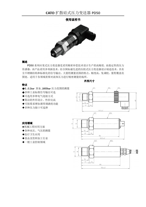
使用说明书概述PD50系列应变式压力变送器是采用精密补偿技术设计生产的高精度、高稳定性的压力传感器,该产品采用多项新技术,结合国际最先进的压阻式压力变送器设计制造技术,具有全不锈钢结构和标准化的信号输出、大量程测量范围的特点,精度高、免调校、量程覆盖范围宽,适用于各领域需要对流体压力进行精密测量的场所。
外形尺寸特点◆0…0.2bar 到0…1600bar压力范围的测量◆多种工业标准信号输出可选◆可选用多种电气连接方式◆简洁的外形设计,性价比高◆可按要求增加调零调满度功能◆多种压力接口可选择应用领域◆机械工程应用方面◆各种水压、气压的测量◆医疗卫生应用◆食品及饮料加工行业◆一般工业控制领域量程:0~1MPa~600MPa 综合精度:0.25%FS ;0.5%FS ;1%FS 非线性:满量程的0.2%FS 重复性:满量程的0.05% 输出信号:4-20mA (两线制), 0-5V ;0-10V (三线制); 供电电压:24(12~36)VDC (放大信号) 工作温度范围:-20~80℃ 补偿温度范围:0~65℃ 过载压力:150%FS 介质材料: 压力接头材质为不锈钢,外壳材质为不锈钢或硬制铝可选择防护等级:电气连接: 赫斯曼(DIN43650),外壳防护IP65;防水格兰,外壳防护IP68;航空插件,外壳防护IP45; 压力连接:G1/4, G1/2, 1/2NPT, 1/4NPT, M12*1.5等(可按客户要求定制) 零位满度调节: 可按要求增加此功能,有外调(分侧调和顶调)和内调,但外形尺寸有变动。
常见电气接头常见接头接线方式12 3 4321GSP123451234。
气动执行器的产品说明书

S E R I E S P L S O L E N O I D V A L V E SDirect acting solenoid valves Series PL2/2-way - Normally Open (NO)3/2-way - Normally Closed (NC) and Normally Open (NO) 3/2-way - Universal (UNI)Series PL solenoid valves are available in the normally closed, normally open and universal versions. They can be mounted on single sub-bases or manifolds.Please note that all Series PL solenoid valves are supplied with direct current (DC). To operate in alternating current (AC), it is necessary to use the connector with bridge rectifier Mod. 125-900.»Application sectors: - Industrial Automation - Life Science - Transportation »Mounting on a single base (M5 connections) or on manifold (M5 or fittings Ø3 and Ø4)GENERAL DATATECHNICAL FEATURES Function OperationPneumatic connections Orifice diameterFlow coefficient kv (l/min) Operating pressure Operating temperature MediaResponse time Manual override Installation2/2 NO - 3/2 NC - 3/2 NO - 3/2 UNI direct acting poppet type on subbase 0.8 ... 1.6 mm 0.30 ... 0.62 0 ÷ 3.5 ... 10 bar0 ÷ 50 °C (FKM) / -50 ÷ 50 °C (low temperature NBR on demand)filtered air class [5:4:4] according to ISO 8573-1:2010 (max oil viscosity 32 cSt), inert gas ON <10 ms - OFF <15 msmono/bistable - PBT 3/2 versions onlyin any positionMATERIALS IN CONTACT WITH THE MEDIUM Body SealsInternal parts brass - PBT - PPSFKM - NBR - EPDM (on demand) brass - stainless steelELECTRICAL FEATURES VoltageVoltage tolerance Power consumption Duty cycleElectrical connection Protection class6 ... 110 V DC - other voltages on demand ±10% 1.2 ... 3 W ED 100%industry standard connector (9.4 mm) IP65 with connectorSpecial versions available on demandS E R I E S P L S O L E N O I D V A L V ES* 3/2 NO IN-LINE version: the position of the ports 1 - 2 - 3 is identical to 3/2 NC versionCODING EXAMPLES E R I E S P L S O L E N O I D V A L V E SSeries PL solenoid valve - 2/2-way NO - series PD interfaceSupplied with: 2x O-Rings2x M3x20 screws for mounting on metal or2x Ø3x23 screws for mounting on plastic(opt. P)* add - VOLTAGE - FIXING(see CODING EXAMPLE)Series PL solenoid valve - 3/2-way NCSupplied with: 1x interface seal2x M3x20 screws for mounting on metal or2x Ø3x23 screws for mounting on plastic (opt. P)Also available ST models forT amb. -50 ÷ 50 °C with NBR seals.* add - VOLTAGE - FIXING(see CODING EXAMPLE)S E R I E S P L S O L E N O I D V A L V E S2x M3x20 screws for mounting on metal or2x Ø3x23 screws for mounting on plastic (opt. P)Also available ST models forT amb. -50 ÷ 50 °C with NBR seals.* add - VOLTAGE - FIXING(see CODING EXAMPLE)Series PL solenoid valve - 3/2-way NO IN-LINESupplied with: 1x interface seal2x M3x20 screws for mounting on metal or2x Ø3x23 screws for mounting on plastic (opt. P)Also available ST models forT amb. -50 ÷ 50 °C with NBR seals.* add - VOLTAGE - FIXING(see CODING EXAMPLE)S E R I E S P L S O L E N O I D V A L V E S2x M3x20 screws for mounting on metal or2x Ø3x23 screws for mounting on plastic (opt. P)Also available models for T amb. -50 ÷ 50 °C with NBR sealsVacuum operation with max. pressurereduction* add - VOLTAGE - FIXING(see CODING EXAMPLE)S E R I E S P L S O L E N O I D V A L V ESSingle sub-base for 15mm size 2 way interfaceSingle sub-base suitable for 2-way solenoid valves Series PD and PL models PD000-2A..., PL000-9B... Use solenoid valves with fixing screws for metal (see codification page)Material: anodized aluminiumConnections: G1/8 threadsSingle sub-base for 3-way solenoid valve size 15 mmSingle sub-base suitable for Series P - PL - PN - W 3-way solenoid valveUse solenoid valves with screws for mounting on metal (see coding)Material: anodized aluminiumConnections: M5 threadsSingle manifold with rear outletsManifold suitable for Series P - PL - PN - W 3-way solenoid valveUse solenoid valves with screws for mounting on metal (see coding)Material: anodized aluminiumS E R I E S P L S O L E N O I D V A LV E SManifold - single side valve - frontal outletsManifold suitable for Series P - PL - PN - W 3-way solenoid valveUse solenoid valves with screws for mounting on metal (see coding)Can be fixed through DIN 46277/3 guide with the accessory PCF-E520.Material: anodized aluminiumManifold - double side valve - bottom outletsManifold suitable for Series P - PL - PN - W 3-way solenoid valveUse solenoid valves with screws for mounting on metal (see coding)Material: anodized aluminiumManifold - double side valve - frontal outletsManifold suitable for Series P - PL - PN - W 3-way solenoid valveUse solenoid valves with screws for mounting on metal (see coding)Can be fixed through DIN 46277/3 guide with the accessory PCF-E520.Material: anodized aluminiumS E R I E S P L S O L E N O I D V A L V ESPosition valve capSupplied with:1x position valve cap 1x interface seal2x screwsConnector Mod. 125-... - industrial std. 9.4 mmConnector Mod. 125-... - industrial std. 9.4 mm - 90° cableThe internal rectifier circuit of the connectorMod. 125-900 allows to use solenoid valves with different AC voltage, even if the voltage indicated onthe solenoid valve is DC.S E R I E S P L S O L E N O I D V A L V E SConnector Mod. 125-... - industrial std. 9.4 mm - in-line cablewithout electronicsConn. Mod. 125-... - ind. std. 9.4 mm - in-line cable+rectifierwith voltage rectifierAC/DC。
CB RoHS LH15系列电源说明书

15W, AC-DC converterFEATURES● Wide input voltage range: 85 - 264V AC/100 - 370VDC ● Regulated output, Low ripple & noise ● High efficiency up to 84%● Output short circuit, over-current, over-voltage protection ● Plastic case, meets UL94V-0● IEC60950, UL60950, EN60950 approval ● Mounting: Chassis mountingCBRoHSLH15 series features universal input voltage, taking both DC and AC input voltage, low power consumption, high efficiency, high reliability, safer isolation. It offers good EMC performance, which meet IEC/EN61000-4, CISPR22/EN55022, UL60950 and EN60950 standards, and it’s widely used in industrial, office and civil applications.Selection GuideRS Stock No. Part No.* Output PowerNominal Output V oltage and CurrentEfficiency (230V AC, %/Typ.)Max. Capacitive Load(µF)1446265 LH15-10B05A2 14W5V/2800mA 76 20000 1446266 LH15-10B12A2 15W 12V/1250mA 80 5200 1446267 LH15-10B15A2 15V/1000mA 80 5000 1446268 LH15-10B24A224V/625mA84900Input SpecificationsItemOperating Conditions Min. Typ. Max. Unit Input V oltage Range AC input 85 -- 264 V AC DC input 100 -- 370 VDC Input frequency 47 -- 63 HzInput current 115V AC -- -- 0.37 A 230V AC -- -- 0.22 Inrush current 115V AC -- 10 -- 230V AC--20--Leakage current0.3mA RMS typ./230V AC/50HzBuilt in input fuse2A/250V , slow blow.Output SpecificationsItemOperating Conditions Min. Typ. Max. UnitOutput V oltage Accuracy Main circuit -- ±2 -- %Line Regulation Full load -- ±0.5 -- Load Regulation 10% - 100% load-- ±1 -- Ripple & Noise* Main circuit 20MHz bandwidth (peak-peak value) -- 50 100 mV Temperature Coefficient Main circuit --±0.02--%/°CShort Circuit Protection Continuous, self-recovery Over-current Protection≥110%Io self-recoveryOver-voltage Protection5VDC Output≤7.5VDC 12 /15VDC Output ≤20VDC 24VDC Output≤30VDCMin. Load Single output 0 -- -- % Hold-up Time115V AC input -- 15 -- ms230V AC input--80--General SpecificationsItem Operating Conditions Min. Typ. Max. UnitIsolation V oltage Input-outputTest time: 1min3000 -- --V AC Input- 2000 -- --Operating Temperature -40 -- +70°C Storage Temperature -40 -- +105Storage Humidity -- -- 95 %RHSoldering Temperature Wave-soldering 260 ± 5℃; time: 5 - 10s Manual-welding 360 ± 10℃; time: 3 - 5sSwitching Frequency -- 65 -- kHzPower Derating -40℃to -10℃ 2.0 -- --%/°C +55℃to +70℃ 4.0 -- --Safety Standard IEC60950/EN60950/UL60950 Safety Certification IEC60950/EN60950/UL60950Safety Class CLASS IIMTBF MIL-HDBK-217F@25°C > 300,000 hPhysical SpecificationsCasing Material Black flame-retardant and heat-resistant plastic (UL94V-0)Dimension 96.10*54.00*31.00mmWeight 135gCooling method Free air convectionEMC SpecificationsEMI CE CISPR22/EN55022 CLASS B RE CISPR22/EN55022 CLASS BEMS ESD IEC/EN61000-4-2 Contact ±6KV/Air ±8KV Perf. Criteria B RS IEC/EN61000-4-3 10V/m perf. Criteria AEFTIEC/EN61000-4-4 ±2KV perf. Criteria BIEC/EN61000-4-4 ±4KV (See Fig. 5 for recommended circuit) perf. Criteria B SurgeIEC/EN61000-4-5 line to line ±1KV/line to ground ±2KV perf. Criteria BIEC/EN61000-4-5 line to line ±2KV/line to ground ±4KV(See Fig. 5 for recommended circuit)perf. Criteria B CS IEC/EN61000-4-6 10 Vr.m.s perf. Criteria A PFM IEC/EN61000-4-8 10A/m perf. Criteria A V oltage dips, short interruptions and voltagevariations immunityIEC/EN61000-4-11 0%,70% perf. Criteria BProduct Characteristic Curve-40 -10 55 7010080604020T e m p e ra ture De ra ting C urveO u t p u t P o w e r P e r c e n t (%)Inp ut vo lta g e :A m b ie n t t e m p e ra t u re ()℃100 - 370V D C85 - 264VA C100240852642040100608075In p u t V o lt a g eA m b ie n t t e m p e ra t u re :25℃In p u t V o lt a g e D e ra t in g C u rv eO u t p u t P o w e r P e r c e n t a g e (%)VA C 120340100370V D CNote:①When input 85 - 100VAC/240 - 264VAC/100 - 120VDC/340 - 370VDC, it need to be voltage derated on basis of temperature derating; ②This product is suitable for use in natural air cooling environments, if in a closed environment, please contact our company’s FAE.L H15-10B24L H15-10B056065 70 75 80 8590 85115130180230264E f f i c i e n c y (%)Input Voltage(VAC)E fficiency Vs Input Voltage(F ull L oad)L H15-10B24L H15-10B056065 70 75 80 8590 102030405060708090100E f f i c i e n c y (%)Output Power Per centage(%)E fficiency Vs Output L oad(Vin=230VAC)DimensionsNote:1. If the product is not operated within the required load range, the product performance cannot be guaranteed to comply with all parameters in the datasheet;2. Unless otherwise specified, parameters in this datasheet were measured under the conditions of Ta=25℃, humidity<75% with nominal input voltage and rated output load;3. All index testing methods in this datasheet are based on our Company’s corporate standards;4. We can provide product customization service, please contact our technicians directly for specific information;5. Specifications are subject to change without prior notice.。
pd232英文说明书(220V)
220V AC
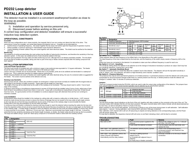
Dip Switch Number Designation 8 Presence Detection ON=Permanent, OFF=Limited 7 Automatic Sensitivity Boost ON/OFF 6 ON OFF ON OFF Medium Medium Sensitivity Loop 1 Low High Low High 5 ON ON OFF OFF 4 ON OFF ON OFF Medium Medium Sensitivity Loop 2 Low High Low High 3 ON ON OFF OFF 2 Frequency Loop 1 ON=Low, OFF=High 1 Frequency Loop 2 ON=Low, OFF=High Dip Switch 1 & 2 – Frequency These switches allow the loop frequency to be shifted high or low depending on the switch position. The ideal frequency of the loop is determined by the loop size, and the frequency of the switch simply causes a frequency shift on the loop. Where two loops are connected to the detector it is advisable to make sure that a different frequency is used for each one. Dip Switch 3, 4, 5 & 6 – Sensitivity The sensitivity setting allows the detector to be selective as to the change of inductance necessary to produce an output. Each loop has four sensitivity selections, ranging from Low to High. Dip Switch 7 – Automatic Sensitivity Boost Automatic sensitivity boost is a mode that alters the “undetect” level of the detector. The detector will use the dip-switch-sensitivity in order to “detect”, and, once detected, will switch to High-Sensitivity until it reaches “undetect” level. Dip Switch 8 – Presence Detection The presence time may be set to permanent presence or to limited presence. In permanent presence mode the detector will continuously compensate for all environmental changes whilst there is a vehicle present over the loop. In limited presence mode the detector will change to “undetect” after 10 minutes of continuous detection. Jumpers There are 3 jumpers located inside the PD-0234, which are used to alter the output relay configuration of the detector. The jumpers have been placed inside the unit to avoid incorrect operation due to selection by an unauthorized operator. ID Designation 1-2 Presence AB-logic LK1 AB-logic 2-3 Pulse AB-logic Open No AB-logic (default) LK5 Channel 1 Output Mode Open: Pulse, Closed: Presence (default) LK6 Channel 2 Output Mode Open: Pulse, Closed: Presence (default)
朗克高压油泵系列PC、PD和PS产品说明说明书

CFluid Power Intensifiers Series PC, PD and PScostly way to provide highpressure hydraulic power.■ Maximum Input Pressures:Air - 250 psi (17 BAR);Oil - 1000 psi (69 BAR).■ 3 1/2" to 5 1/2 RAM -3000 psi (206 BAR).■Parker Fluidpower IntensifiersDesigned to Save Energy, Time, Space and Money in a Wide Variety of Applications.A Parker Fluidpower Intensifier is an efficient way of generating high pressure hydraulic fluid. Its operation is quite simple.Pressurized fluid – either air or oil – enters the intensifier and acts on a confined piston. This in turn drives a smaller diameter ram or piston to deliver a given volume of fluid. As a result, the output pressure is intensified and is considerably higher than the input pressure.By using a Parker Intensifier you can save in many ways. First,since it requires only low pressure input and less costly control valving, you eliminate the extra expense of high pressure pumps,valving and a large electrical power sources. The simplermountings and controls also save you valuable installation time.In addition, since Parker Intensifiers produce high hydraulic pressure, you can save space by using a smaller bore hydraulic cylinder in place of a larger bore air cylinder that is heavier and more costly.Finally, because of the rugged dependability of Parker Intensifiers and the simpler circuitry required, you eliminate the constant motion, heat generation and power consumption found in pump systems. This means that you use less energy with less downtime and maintenance.These abilities and benefits of Parker Fluidpower Intensifiers make them the ideal component in many applications. You can use them for such operations as marking, forming, molding,punching, riveting, shearing, straightening, laminating, emboss-ing, welding and testing.What’s more, the Parker Intensifier can be mounted on or off the equipment and can even be integrally combined with the work cylinder. This flexibility makes them particularly useful hydraulic pressure sources on portable equipment.Parker Fluid Intensifiers are available in various sizes andconfigurations. There are cylinder-to-ram units with capability for either single pressure or dual pressure service (left above), as well as several cylinder-to-cylinder models (above right).Here are the features you’ll find in every Parker Fluidpower Intensifier:1. Compact, high-strength steel heads, cap and tie rods meet the most demanding applications.2. Seal by pressure O-rings serve as cylinder body-to-head seals prevent leaks. Thecylinder body is also piloted on the O.D. to insure metal-to-metal contact to support the seals.3. The rugged one-piece iron piston is threaded and Loctited to the ram. Parker Lipseal ®piston seals are used with air;piston rings with hydraulic fluid.4. The driving cylinder body is steel tubing with chrome-plated bore for corrosion-resistance in bore sizes 31/4"through 10". Fiber glass is used on 12" and 14" bore sizes.5. The smooth, wear-resistant surface of the chrome-plated and induction-hardened ram greatly lengthens seal life.6. Static O-ring seals prevent leaks past the O.D. of the glands.Back-up washers prevent extrusion.7. Intensifier operation is speeded up by the free flow of fluid in and out of the unobstructed ports. All high-pressure hydraulic ports are SAE straight thread. O-ring type for leak-proof service.8. Serrated Lipseals ® (Patent 2997318) are self-compensating and self-adjusting to provide leakproof ram seal for both high and low pressure operation.9. For servicing the high pressure ram seals, the pressurechamber is independently secured with studs so it can be easily removed without disassembling the complete intensifier.10. For optimum strength and safety, the pressure chamber wall is made of extra thick steel tubing that is piloted in a counterbore and pressure-welded to the head.This basic circuit is for a dual pressure system supplying pressureto a double-acting work system. The circuit may be readilyA Cutoff ValveB Air Preparation Unit (Filter Regulator Lubricator-Gauge)C 4-Way Valve (Normally 2 Position)D 3-Way ValveTank Fluid Levels)F Advancing Tank (Air-Oil)G Retracting Tank (Air-Oil)H IntensifierI Work Cylinder1234156789810CStep 1: Determine the intensifier ratio for your application. This is the ratio of the available input fluid pressure and the output operating pressure required for the application. For cylinder-to-ram or cylinder-to-cylinder units, use the following formula:Intensifier ratio =Output pressure Input pressureStep 2: Locate the intensifier ratio in column 5 of the appropriate chart on page 3. If the exact ratio is not shown, use the next larger ratio listed. When more than one choice is possible, usually the smallest driving cylinder bore size for a given intensifier ratio is the most economical answer.Step 3: On same horizontal line as ratio determined in Step 2,select the driving cylinder bore size from column 1 and the ram diameter or driven cylinder bore size from column 3.Note: For cylinder-to-ram applications, proceed with Steps 4 and 5. If a cylinder-to-cylinder unit is required, go to Step 6.Step 4: Determine the type of cylinder-to-ram intensifier needed.Generally, a single pressure intensifier is used when the hydraulic work cylinder requires a high pressure for the entire stroke or in test vessel applications. A dual pressure intensifier is recom-mended if the high pressure is to be used only during the last portion of the work cylinder stroke.Step 5: Calculate the intensifier stroke.For single pressure intensifiers, use the formula:Intensifier stroke =V + V cA rFor dual pressure intensifier, use this formula:Intensifier stroke =V h + V cA rWhere: V = Work cylinder volume or test vessel fluid requirementin cubic inches.V h = oil volume in cubic inches required to move the work cylinder piston through its high pressure stroke.V c = compressibility allowance of 1% per 1000 psi of total volume in cubic inches of oil in the high pressure circuit,determined from:V c = total volume x .01 x high pressure/1000.A r = area of intensifier ram in square inches.changed for other operating conditions such as single acting cylinder and single pressure delivery.The input pressure is introduced to the system through shop air lines to the 4-way directional control valve C. When valve C isshifted to position as shown, air is directed into air-oil tank F and to valve D. Oil, acted upon by air pressure, is forced from tank through pressure chamber of retracted intensifier and into work cylinder. The cylinder advances in stroke, being driven by this incoming oil. At a predetermined point in the stroke length of the work cylinder, valve D is synchronized to shift and direct air pressure to the intensifier to drive it in its power stroke, isolating tank F and supplying high pressure to work cylinder for its high thrust stroke. The work cylinder and intensifier are retracted by the shifting of valves C and D simultaneously to exhaust the intensifier and tank F. At the same time, air pressure is directed to tank GHow to Select Parker Fluidpower IntensifiersNote: If the calculated intensifier stroke results in a fraction,correct to the next larger even inch. The recommended maximum stroke is 20". If stroke calculation results in longer than 20" stroke,select a larger driving cylinder and ram having a similar intensi-fier ratio and recalculate stroke.Step 6: For cylinder-to-cylinder intensifiers: Select the properoutput cylinder. Since the output pressure is limited by the cylinder construction, the cylinder should be selected using the maximum pressure to be developed under nonshock conditions.For Parker Series 3L and 2H hydraulic cylinders, the maximum pressures under nonshock conditions are:3L Series:11/2"–2500 psi;2"–2000 psi;21/2"–1800 psi;31/4"–2000 psi;4"–1350 psi;5"–1500 psi;6"–1100 psi;8"–900 psi2H Series: All bore sizes – 3000 psi.General Guidelines1.Intensifiers are generally faster operating when:a. There is adequate input pressure.b. The ports and piping are large enough. Consider the use of oversize ports and connecting lines, to minimize pressure drop.c. The intensifier is pre-exhausted prior to the power stroke.d. Size hydraulic lines so that fluid flow velocity does not exceed 7 feet per second.2.Bypass the intensifier with a pre-fill low pressure line by direct connection through a check valve to the pressure vessel.3.Regulate the driving pressure to the intensifier to achieve the required high pressure output.4.Keep all piping lengths to a minimum by having the tanks,intensifier and pressure vessel as close together as possible.5.A single pressure intensifier usually provides faster cylinder action because it does not need to change from low to high pressure but instead immediately supplies the high pressure.6.Intensifiers are generally used in circuits where limited quantities of high pressure fluid is required.and to rod end side of intensifier piston. Oil from tank G retracts cylinder at low pressure.The operators for valves C and D are optional – mechanical,manual, pilot or solenoid. The method of synchronizing valve D to stroke length position of work cylinder is also optional. This may be done by pilot control, limit switch, pressure switch, mechani-cally such as cams, or manually.*This 2" is the intensifier stroke advance necessary to close the high pressure seal on dual pressure intensifiers only.+ 2"*Fluidpower IntensifiersSelection Sizing(Series PS and PD) Cylinder to Ram Intensifiers1000Col. 11345026404000256040002780204040002940500Col. 102795172513204230261520001280408031252000139010204500288020001470355516154080200Col. 9211411186905283200169210468005125002264416321250800556408381023521800115280058841803200104814221046500032002222163246083200235043563200100Col. 82702105755934526440931600846523400256250113228166254002782043601190511769005764002943385209016001024711523326625001600111181647023600230416001175489931362178160080Col. 7216184644727621132741280677418320205511620001058653500320222163288015249417204613202355122270816721280819569418423126132000128088965337612880184312809405120391925091742128050Col. 61351529280173132204680042326220012831971250661408313200139102180095358845028820014732011693104580051235626226441633125080055640838082351180011528005883200244915681089800IntensifierRatio Col. 527.0210.575.593.452.6440.9316.008.465.234.002.5663.9525.0113.228.166.254.002.782.0436.0119.0511.769.005.764.002.9464.0333.8520.9016.0010.247.115.2352.8932.6625.0016.0011.118.1676.1647.0236.0023.0416.0011.7564.0048.9931.3621.7816.00Area of VolumeD ispl. Per in StrokeCol. 4.307.7851.4852.4053.142.307.7851.4852.4053.1424.909.307.7851.4852.4053.1424.9097.0699.621.7851.4852.4053.1424.9097.0699.621.7851.4852.4053.1424.9097.0699.6211.4852.4053.1424.9097.0699.6211.4852.4053.1424.9097.0699.6212.4053.1424.9097.0699.621Dia.Col. 35/811 3/81 3/425/811 3/81 3/422 1/25/811 3/81 3/422 1/233 1/211 3/81 3/422 1/233 1/211 3/81 3/422 1/233 1/21 3/81 3/422 1/233 1/21 3/81 3/422 1/233 1/21 3/422 1/233 1/2Area Col. 28.29612.56619.63528.27450.26578.540113.10153.94Bore Col. 13 1/44568101214Driving Cylinder Hydraulic RamTheoretical IntensifiedHydraulic Pressure (PSI) UsingAn Input Pressure Of(Series PC) Cylinder to Cylinder Intensifiers1000Col. 112640*4000*2560*4000*2370*3410*2250*14404000*2560*1780*4000*2780*4000*2940*2250*4000*3060*500Col. 10234513203555*200012803125*2000*11854500*2880*170511257203030*2000*12808904735*3125*2000*1390*4500*2880*2000*1470*1125*3920*1725*2000*1530*200Col. 9938528142280051222221250800474180011526824501883200*204812128005123563200*189412508005562728*1800*1152800588*4502450*1568*1090800*612100Col. 846926471140025611116254002379005763412251441600102460640025617816009476254002781364900576400294*2251225784545400*30680Col. 7375211569320205889500320190720461273180115128081948532020514312807585003202231091720460320235*180980227436320*24550Col. 62351323562001285563132001194502881711137280051230320012889800474313200139682450288200147*113613392273200*153Intensifier Ratio Col. 54.692.647.114.002.5611.116.254.002.379.005.763.412.251.4416.0010.246.064.002.561.7816.009.476.254.002.7813.649.005.764.002.942.2512.257.845.454.003.06Area Col. 41.7673.1421.7673.1424.9091.7673.1424.9098.2963.1424.9098.29612.56619.6353.1424.9098.29612.56619.63528.2744.9098.29612.56619.63528.2748.29612.56619.63528.27438.48550.26512.56619.63528.27438.48550.265Bore Col. 31 1/221 1/222 1/21 1/222 1/23 1/422 1/23 1/4452 2 1/23 1/44562 1/23 1/44563 1/44567845678Area Col. 28.29612.56619.63528.27450.26578.540113.10153.94Bore Col. 13 1/44568101214Driving Cylinder Theoretical Intensified Hydraulic Pressure (PSI) UsingAn Input Pressure OfDriving Cylinder *Not recommended for Series 3L driven cylinder, use Series 2H.Cylinder to Cylinder Intensifier – Series PCCFluidpower IntensifiersDimensions and MountingsParker Fluid Power Cylinder to Cylinder Intensifiers (Series PC)Series PC Intensifiers consist of two cylinders joined into an integral unit with one piston driving a second piston of smaller diameter. These intensifiers are not self-bleeding or self-filling, therefore, for the most effective operation, it is recommended that these tasks be done manually.Special Note: It is recommended that Series PCcylinder-to-cylinder intensifiers be mounted vertically with the smaller cylinder up.MTG Styles are:HBA – Air Input HBL – Hyd. InputMounting Style TCCap Tie Rods ExtendedThis mounting available in driving cylinder bore sizes 31/4-inches through 14-inches.MTG Styles are:TCA Cap End – Air Input TCL Cap End Hyd. InputAPSFluidpower IntensifiersDimensions MountingsParker Fluid Power Cylinder to Ram Dual Pressure Intensifiers (Series PD)Series PD Intensifiers are similar to the Series PS units except a center head has been added to retain another gland and a third ram seal. When the ram is fully retracted, it withdraws from this third seal, allowing the low pressure the low pressure hydraulic fluid to flow through the port in the center head. The fluid then goes past the ram and out the pressure chamber port to prefill and advance the work cylinder. Actually, this third seal and the ram act as a check valve. As the circuit sequences, the ram advances into the seal to close this “valve” and build up highpressure. With this arrangement and the proper mounting, Series PD intensifiers are self-bleeding and self-filling. And theseSpecial Notes: 1. When equipped with integral air-oil tanks, Series PD intensifiers have a maximum input pressure of 150 psi.2. It is recommended that Series PD dual pressure intensifiers be mounted vertically with the pressure chamber down.Mounting Style CB –End AnglesMounting Style TBHead Tie Rods Extended(Styles TC – Cap Tie Rods Extended and TD – Both Ends Tie Rods Extended are also available. Dimensions “BB”remains the same in all cases.)Mounting Style TBHead Tie Rods Extended with Integral Air-Oil Tank Mounting Style CB –End Angles with Integral Air-Oil Tanks+CParker Fluid Power Cylinder to Ram Single Pressure Intensifiers (Series PS)Series PS Intensifier delivers a single pressure through a double acting piston driving a ram. One seal on the ram gland works on the driving piston side; the other on the pressure chamber side. Since this intensifier is neither self-bleeding nor self-filling, for best performance it is recom-mended that these tasks be performed manually.Special Note: It is recommended that Series PSsingle pressure intensifiers be mounted vertically withMounting Style CB – End AnglesMounting Style TCCap Tie Rods Extended(Style TB – Head Rods Extended, and TD – Both Ends Tie Rods Extended, are also available. Dimension “BB” remains the same in all cases.)Fluidpower IntensifiersDimensions and MountingsWARNINGFAILURE OR IMPROPER SELECTION OR IMPROPER USE OF THE PRODUCTS AND/OR SYSTEMS DESCRIBED HEREIN OR RELA TED ITEMS CAN CAUSE DEA TH, PERSONAL INJUR Y AND PROPERTY DAMA GE.This document and other information from Parker Hannifin Corporation, its subsidiaries and authorized distributors provide product and/or system options for further investigation by users having technical expertise. It is important that you analyze all aspects of your application, including consequences of any failure and review the information concerning the product or system in the current product catalog. Due to the variety of operating conditions and applications for these products or systems,the user, through its own analysis and testing, is solely responsible for making the final selection of the products and systems and assuring that all performance,safety and warning requirements of the application are met.The products described herein, including without limitation, product features, specifications, designs, availability and pricing, are subject to change by Parker Hannifin Corporation and its subsidiaries at any time without notice.!How To OrderWhen ordering Parker Intensifiers, please specify:a. Quantityb. Driving Cylinder bore sizec. Mounting style – specify by using style letters given beneath dimension drawings.d. Driving cylinder operating fluid mediume. Intensifier series (PS, PD or PC)How To Order Parker Fluidpower IntensifiersModel NumbersEach Parker Fluidpower Intensifier has a model number.This, along with the driving cylinder bore size and stroke,is an accurate and coded description of the unit. The chart When Ordering Fluid Power Intensifiers By Model Numberf. Intensifier ram diameter (for cylinder-to-ram intensifiers)or Output cylinder bore (for cylinder-to-cylinder units)g. Driving cylinder strokeh. Input pressure, output pressure and volumeNote: Standard intensifiers are designed for use with petroleum base hydraulic oil. If other fluids will be used,please consult the factory.here shows the elements of these model numbers. It is provided so that you can check our order acknowledgement against your order.Intensifier Ram (or D riven Cylinder)Diameter Specify From Dimension TablesDriving Cylinder Bore 3 1/4,4, 5, 6,8, 10,12 or 14Driving Cylinder Mounting Style CB,TB, TC,TD, H or HB Driving Cylinder Operating Fluid 2A (Air)or 3L* (HYD.)SpecifyOne SeriesOnlyIntensifier SeriesPD,PS, PC Driven Cylinder Series PC Only 2H (3000 PSI Maximum)or 3L (900 to 2500 PSI Maximum Depending on Bore SizeSpecial FeaturesS Use Only if Intensifier Varies From CatalogDriving Cylinder Stroke Specify For PD Style See Note Below–X NOTE: PD style intensifiers require 2" additional stroke to seal the high pressure end. See Page 61.*3L supplied with cast iron piston rings unless otherwise specified.SpecificationsMaximum Input Pressures:Air - 250 psi (17 BAR); Oil - 1000 psi (69 BAR).Maximum Output Pressures:5/8" to 3" RAM - 5000 psi (345 BAR);3 1/2" to 5 1/2 RAM - 3000 psi (206 BAR).Maximum Operating Temperatures:-10°F to +165°F (-23°C) to (+74°C).。
PD30CNB15 密闭感应器系列说明说明书

Product DescriptionThe PD30CNB15 sensor family comes in a compact 10 x 30 x 20 mm reinforced PMMA/ABS housing. The sensors are useful in applications where high-ac-curacy detection as well as small size is required. Compact housing and high power LED for excellent performance-size ratio.The Teach-In function for adjustment of the sensitivi-ty makes the sensors highly flexible. The output type is preset (NPN or PNP), and the output switching function is NO or NC output.A remote teach feature allow the sensor to be set up from e.g. a PLC.• Miniature sensor range • Range: 150 mm• Sensitivity adjustment by Teach-In programming • Modulated, red light 660 nm • Supply voltage: 10 to 30 VDC• Output: 100 mA, NPN or PNP preset• Make or break switching function programmable • LED indication for output, stability and power ON• Protection: reverse polarity, short circuit and transients • Cable and plug versions • Excellent EMC performance • Remote teach featuresPhotoelectricsDiffuse-reflective, Background Suppression Type PD30CNB15....RTType SelectionHousing Range Connection Ordering no. Ordering no. W x H x D S n NPN PNPMake or break switching Make or break switching10 x 30 x 20 mm 150 m m Cable PD 30 CNB 15 NPRT PD 30 CNB 15 PPRT 10 x 30 x 20 mm150 m mPlugPD 30 CNB 15 NPM5RTPD 30 CNB 15 PPM5RTSpecifications EN 60947-5-2PD30CNB15....RTSpecifications (cont.)Wiring DiagramsOperation DiagramPower supply ObjectOFF ONPresent Operation DiagramBreak Output (N.C.)Make Output (N.O.)OFF ONOFFONtv = Power ON delayDetection Diagram-5-4-3-2-1012345050100150200Sensing range (mm)(m m )Sensing Conditions051015202530020406080100120140160Distance (mm)% o f s e n s i n g d i s t a n c e5% / 90%90% / 90%18% / 90%5% / 90%18% / 90%90% / 90%Black on WhiteGrey on WhiteWhite on WhiteDelivery Contents• Photoelectric switch: PD 30 CNB 15 ...• Installation instruction• Mountingbracket APD30-MB1• Packaging: Cardboard boxPD30CNB15....RTDimensionsAccessories• Mounting bracket APD30-MB2 to be purchased seperately • Connector type CONG 5A../CON. 54NF.. series.Installation HintsNormal operation, optimized switching point.1. Line up the sensor at the background. Yellow LED isnot important and Green LED is ON.2. Press the button for 3 seconds until both LEDsflashes simultaneously.(The first switch point is stored)3. Place the object in the detection zone.4. Press the button once and the sensor is ready tooperate (Green LED ON, Yellow LED ON)(The second switch point is stored)a) if the object is to close to the background thesensor will teach both background and object asobject.For maximum sensing distance(default setting)1. Line up the sensor without a background. Yellow LEDis not important and Green LED is ON.2. Press the button for 3 seconds until both LEDsflashes simultaneously.(The first switch point is stored)3. Press the button a second time and the sensor isready to operate (Green LED ON, Yellow LED ON)(The second switch point is stored)For minimum sensing distance1. Line up the sensor at the object. Yellow LED is notimportant and Green LED is ON.2. Press the button for 3 seconds until both LEDsflashes simultaneously.(The first switch point is stored)3. Press the button a second time and the sensor isready to operate(Green LED ON, Yellow LED ON)(The second switch point is stored)For dynamic set-up (running process)1. Line up the sensor at the object. Green LED is ON,status on the yellow LED is not important.2. Press the button for 3 second until both LEDsflashes simultaneously.3. Press the button a second time for at least onesecond, both LED’s flashes fast siultainiously andkeep the button pressed for at least one processcycle, release the button and the sensor is readyto operate (The second switch point is stored)For make or break set-up (N.O. or N.C.)1. Press the button for 10 seconds, until the greenLEDs flashes.2. While the green LED flashes, the output is invertedeach time the button is pressed. Yellow LED indi-cates N.O. function selected.If the button is not pressed within the next 10seconds, the current output is stored.Teach functionsPD30CNB15....RT10 sec.Push once。
Mini-Circuits产品说明书

6
0.7
1.15 1.60 1.05 1.30 UU179
C O
PRICE
N N
$
E
C
T
I
Qty.
O N
(1-9)
kf 79.95 kf 139.95
— 172.95 — 182.95 — 172.95 — 189.95 — 189.95
— 349.00 — 295.00 — 295.00 — 265.00
POWER SPLITTERS/COMBINERS
12 WAY-0° 1 to 1700 MHz
50&75Ω
ZFSC-12
SURFACE MOUNT
ZN12PD
JEPS-12
PSC-12
MODEL NO.
u JEPS-12-10 PSC-12-1
FREQ. RANGE
MHz
fL-fU
50-1000 1-200
ZC16PD-24 ZC16PD-900 ZC16PD-960 ZC16PD-960W
650-2400 800-900 890-960 700-1000
ZC16PD-1900 ZC16PD-1900W ZC16PD-23 ZC16PD-2185
1700-1900 1500-2100 1500-2300 1800-2600
25 14 30 20 28 20 26 15
30 20 30 15 32 20 30 16
1.5 2.5 1.9 3.5
3.0 4.2 2.2 4.0
1.1 1.3 0.7 1.1 0.5 0.9 0.4 0.8 0.7 1.0
1.2 1.4 1.0 1.3 0.5 0.9 1.0 1.6 0.9 1.5
数字手持终端PD60X数字便携电台使用说明书

DIGITAL PORTABLE RADIO数字手持终端OWNER’S MANUAL使用说明书Instructional IconsIndicates functions that are available on digital channel only.Indicates functions that are available on analog channel only.Functions marked with no function icons are available on both analog and digital channels.DisclaimerThe Company endeavors to achieve the accuracy and completeness of this manual, but no warranty of accuracy or reliability is given. All the specifications and designs are subject to change without notice due to continuous technology development. No part of this manual may be copied, modified, translated, or distributed in any manner without the express written permission of us.We do not guarantee, for any particular purpose, the accuracy, validity, timeliness, legitimacy or completeness of the Third Party products and contents involved in this manual.If you have any suggestions or would like to learn more details, please visit our website at:.RF Radiation InformationThis product must be restricted to operations in an Occupational/Controlled RF exposure Environments. Users must be fully aware of the hazards of the exposure and able to exercise control over their RF exposure to qualify for the higher exposure limits.RF Radiation ProfileRadio Frequency (RF) is a frequency of electromagnetic radiation in the range at which radio signals are transmitted. RF technology is widely used in communication, medicine, food processing and other fields. It may generate radiation during use.RF Radiation SafetyIn order to ensure user health, experts from relevant industries including science, engineering, medicine and health work with international organizations to●United States Federal Communications Commission, Code of Federal Regulations; 47CFR part 2 sub-part J;●American National Standards Institute (ANSI)/Institute of Electrical and Electronic Engineers (IEEE) C95. 1-1992;●Institute of Electrical and Electronic Engineers (IEEE) C95.1-1999;●International Commission on Non-Ionizing Radiation Protection (ICNIRP) 1998.FCC RegulationsFederal Communication Commission (FCC) requires that all radio communication products should meet the requirements set forth in the above standards before they can be marketed in the U.S, and the manufacturer shall post a RF label on the product to inform users of operational instructions, so as to enhance their occupational health against exposure to RF energy.Operational Instructions and Training GuidelinesTo ensure optimal performance and compliance with the occupational/controlled environment RF energy exposure limits in the above standards and guidelines, users should transmit not more than 50% of the time and always adhere to the following procedures:●RF energy will be generated only when the radio is transmitting.●The radio must be 2.5 centimeters away from human body when transmitting.EU Regulatory ConformanceAs certified by the qualified laboratory, the product is in compliance with the essential requirements and other relevant provisions of the Directive 1999/5/ EC.Please note that the above information is applicable to EU countries only.Contents1. Items in the Package ------------------------------------12. Product Overview -----------------------------------------2Product Controls ---------------------------------------------------2 Programmable Keys ----------------------------------------------3 3. Before Use --------------------------------------------------3Assembling the Radio --------------------------------------------3 Charging the Battery ----------------------------------------------4 Checking the Battery Power ------------------------------------5 4. Status Indication ------------------------------------------5LED Indicator -------------------------------------------------------55. Basic Operations -----------------------------------------6Powering On/Off ---------------------------------------------------6 Adjusting the Volume ---------------------------------------------6 Selecting a Zone ---------------------------------------------------6 Selecting a Channel -----------------------------------------------66. Call Services------------------------------------------------7Calling on Digital Channel ----------------------------------7 Calling on Analog Channel (No Signaling) --------------8 Emergency Alarm -------------------------------------------------87. Feature Description --------------------------------------88. Troubleshooting -------------------------------------------109. Care and Cleaning ----------------------------------------1110.Optional Accessories -----------------------------------12Product ControlsProgrammable KeysFor enhanced convenience, you may request your dealer to program the SK1 key as shortcut to certain feature. Please refer to the corresponding Feature Book for feature details.Assembling the Radio●To remove the battery, please turn off the radio first. Then slide the battery latch upwards to unlock the battery. ●If not assembled with battery specified by Hytera, the radio will give an alarm tone to remind you when powering on. Afterwards, it will operate normally.”Assemble DisassembleNote3. Assembling the Belt Clip12Remove the screws Assemble the Belt Clip Charging the Battery Please use the charger specified by the Company, and follows thecharging steps as shown below.Read the Safety Information Booklet in advance to get necessary safety information. ●To achieve optimal battery performance, please charge Do not swing the radio when holding it by the antenna, so as to avoid lowering the performance and shortening the life span of the antenna.CautionChecking the Battery PowerYou may check the current battery power by holding the programmed Battery Power Indicator key preset by your dealer. Release the key to exit.LED IndicatorPowering On/Off Adjusting the Volume Selecting a ZoneYou can include a group of channels with the same property in to a zone for convenient management. The radio supports three zones, each of which consists of up to 16 channels. You can switch to the appropriate zone by pressing the programmed Zone Up or Zone Down key presetSelecting a ChannelAfter the radio is powered on, you can rotate the Channel Selector knob to select an appropriate channel. You can also switch to the designated channel directly by pressing the programmed Preset Channel key preset by your dealer.If the Channel Notify feature is enabled by your dealer, the radio will play the channel number upon channel switching.Selecting a Zone Selecting a ChannelAfter the radio is powered on, you can make different kinds of calls. To ensure optimal volume of the receiving radio, keep the microphone about 2.5 to 5 centimeters away from your mouth when transmitting.The types of calls you may initiate are listed below:●Private call: A call made to a private contact.●Group call: A call made to the group contacts.●All call: A call made to all the contacts on the current channel.Calling on Digital ChannelYou can initiate a private call, group call or all call (your radio must be programmed to allow you to use the all call service) through the same operations on digital channel. When calling back, the radio will make programmed to allow you to call back in an all call); but in group call, the radio will make a call to all parties involved when calling back.Here we take the private call as example to illustrate the call process:1. User A and B select the same digital channel.2. User A holds down the PTT key to initiate a call.You preset a regular private call/group call/all call contact for each digital channel via your dealer.3. User A can talk to the microphone when the LED indicator on theradio glows red.4. User A releases the PTT key to finish talking.User A can hold down the PTT key to talk when the LED indicator on the radio is glowing orange.When receiving, the LED indicator on the radio glows green.5. User B can receive the call without any operation. When receiving,the LED indicator glows green.6. User B can hold down the PTT key to talk when the LED indicator onthe radio is glowing orange.The duration of LED indicator glowing orange (Call HoldTime) is preset by your dealer. If neither one talks beforethis duration expires, the call will end.NoteCalling on Analog Channel (No Signaling)On the analog channel without signaling, the calling operations are the same as on the digital channel. The difference is that the called parties are all the users on the channel, rather than the preset contact for the channel.Please refer to the corresponding Feature Book for calling operations on the analog channel with signaling.Emergency AlarmIn case of emergency, you can use this feature to inform your colleagues or control center for help. The Emergency Alarm has the highest priority which can terminate the ongoing activities on the current channel. You can make emergency call even when your radio is transmitting or receiving.Emergency Alarm feature needs to be configured and enabled by your dealer. Please refer to the corresponding Feature Book for details. Available features of this radio are listed below. Please refer to the corresponding Feature Book for details.Feature Type Detailed FeatureRadio Features●Radio setting: Power Level, Covert Mode●Convenient functionality: Shortcuts, One TouchCall and VOX●Security: Man Down (Optional) and LoneWorker●Rent●Audio OptimizationConventionalCommon Features●Scan●Talk AroundTo guarantee optimal performance as well as a long service life of theproduct, please follow the tips below.Product CareKeep the product far away from substances that cancorrode the circuit.Product Cleaning●Clean up the dust and fine particles on the product surface andcharging piece with a clean and dry lint-free cloth or a brush regularly.●Use neutral cleanser and a non-woven fabric to clean the keys,control knobs and front case after long-time use. Do not usechemical preparations such as stain removers, alcohol, sprays or oilpreparations, so as to avoid surface case damage.●Make sure the product is completely dry before use.CautionH M N O4X1 series programming cable with USBportThe following items are the main optional accessories for the radio. Formore information of other accessories, please consult your local dealer.Use the accessories specified by Hytera only. If not, theCompany shall not be liable for any losses or damagesarising out of use of unauthorized accessories.CautionMCA08 MCU Multi-unit Rapid-rate Charger (forLi-Ion/Ni-MH batteries),CH10A06 Dual-Pocket MCU Charger Kit(forLi-Ion/Ni-MH battery, including Dual-PocketCharger and Switching Power),PS7501 AC/DC Adaptor,MCA05 Battery Optimizing SystemX1 series 3-wire Surveillance Earpiece with TransparentAcoustic Tube (Beige),X1 series Remote Earbud,X1 series Remote Swivel Earset,X1 series Remote C-Earset,X1 series Remote Earpiece with Transparent AcousticTubeNCN011 Nylon Carrying Case图标说明:表示数字信道独有的功能,只能在数字信道上使用。
平板电脑说明书

PD0705说明书目录1前言2注意事项3准备使用3.1产品包装内容清单3.2产品外观3.3按键功能说明3.4产品功能3.5产品技术规格参数4快速指南4.1 开/关机4.2 电池管理及充电4.3 桌面功能图标定义5 功能及其应用5.2 网络功能5.2.1 WIFI上网5.2.2 有线宽带上网5.2.3 3G移动上网5.3 USB-HOST 扩展应用5.3.1 外接U盘功能5.3.2 外接鼠标、键盘5.3.3 使用TF存储卡5.4 工具软件5.4.1 APK软件管理器5.4.2 资源管理器5.4.3 高级任务管理器5.4.4 日历5.4.5 计算器5.5 娱乐功能5.5.1 音乐功能5.5.2 视屏功能5.5.3 图片浏览功能5.5.4 照相、摄像功能5.5.5 录音功能5.5.6 电子书功能5.6 网络应用5.6.1 G-MAIL5.6.2 个人、企业E-MAIL注册登录5.6.3 电子市场5.6.4 地图5.6.5 在线视频5.6.6 在线聊天5.6.7 网页浏览5.7 设置5.7.1 无线与网络设置5.7.2声音设置5.7.3 显示设置5.7.4 位置及安全5.7.5 应用程序设置5.7.6 帐户与同步5.7.7 隐私权设置5.7.8 储存设置5.7.9 语言及键盘设置5.7.10 语言输入输出设置5.7.11 日期及时间设置5.7.12 关于设备5.8 桌面功能图标设置5.8.1 桌面快捷操作5.8.2 桌面添加、删除图标5.9 输入法选择及设置6 疑难解答1.前言尊敬的用户:您好!首先感谢您选用本公司生产的产品!本产品内置高性能WiFi接收模块,支持外挂3G USB-DONGLE无线上网卡,接入宽频无线互联网,不受网线束缚,也将带您进入便携影音播放世界,满足您的娱乐需求,同时可以有线接入宽带;它还支持图片浏览、电子书、游戏、网络聊天、移动办公等多种功能,多种设置尽显您的个性。
在使用您的平板电脑之前,请仔细阅读我们随机提供的所有资料。
GCS数显表说明书

GCS 系列(中文液晶显示)数显表说明书两轴数显表、叁轴数显表、火花机专用数显表深圳市恒兴星精密仪器有限公司SHENZHEN HENGXINGXING PRECISION INTRUMENTS CO.LTD.目录目录 (1)结构原理 (1)第一章基本操作说明 (2)一、开机 (2)二、清零 (2)三、公./英制转换 (2)四、自动分中 (3)五、绝对/相对/1000组用户坐标系 (3)第二章1000 组辅助零位功能 (5)第三章专用功能 (6)一、圆周分孔 (6)二、斜线分孔 (8)三、圆弧分孔 (10)四、斜面(斜度)加工 (14)第四章放电加工功能 (16)一、设置放电加工参数 (17)二、EDM加工 (18)三、圆周分孔、斜线分孔与EDM功能结合使用 (25)第五章计算器功能 (26)一、进入和退出计算器功能 (26)二、计算器结果转移 (26)第六章内部参数设定 (27)一、进入内部参数设定,退出内部参数设定 (27)二、设置光栅尺计数方向 (28)三、设置线性误差修正值 (28)四、设置光栅尺解析度 (29)五、设置继电器动作模式 (30)六、10设置SDM置数模式 (30)七、系统总清 (31)结构原理本公司生产的GCS系列的数显表,是一种为机床、磨床、铣床、镗床和火花机提供的位置检测的精密测量仪表。
其工作原理如下:光栅尺数显表GCS系列数显表规格输入电压范围85V-250V最大功耗15W工作温度0℃-40℃储存温度-20℃-40℃相对温度<90%重量约1.45kg尺寸295×185×45(单位:mm)坐标数2(GCSM-2), 3(GCSM-3,GSSE)操作键盘密封薄膜式轻触键盘光栅尺接口9PD/7PD/15PD光栅尺信号两路相差90°相位角的TTL方波,驱动能力>10mA 光栅尺解析度0.05μm,0.1μm,0.2μm,0.5μm,1μm,2μm,5μm,10μm,20μm,50μm,10种GCSEDM接口输出一路开关信号,驱动电源>100mA选购RS232接口一路TX,RX信号外部寻边接口5V高电平,驱动电流>10mA第一章基本操作说明一、开机功能介绍:开电源开关,数显表进入正常显示状态。
英威腾变频器说明书

【精品】INVT英威腾变频器说明书CHE说明书(13版) 目录安全注意事项………………………………………………………………………51 概况…………………………………………………………………………………61.1 变频器的综合技术特性…………………………………………………………61.2 变频器铭牌说明…………………………………………………………………71.3 变频器系列机型…………………………………………………………………71.4 变频器各部件名称说明…………………………………………………………91.5 变频器外形尺寸………………………………………………………………102 开箱检查………………………………………………………………………133 拆卸和安装……………………………………………………………………14 安全警告………………………………………………………………………14 3.1 变频器安装运行环境……………………………………………………15 3.2 变频器安装间隔及距离…………………………………………………16 3.3 外引键盘的安装尺寸……………………………………………………17 3.4 盖板的拆卸和安装………………………………………………………184 接线……………………………………………………………………………20 安全警告………………………………………………………………………20 4.1 与外围设备的连接图……………………………………………………21 4.2 接线端子图………………………………………………………………22 4.3 标准接线图………………………………………………………………23 4.4 断路器、熔断器、电缆、接触器规格一览表…………………………24 4.5 主回路的连接……………………………………………………………25 4.5.1 主回路电源侧的连接…………………………………………… 25 4.5.2 主回路变频器侧的连接…………………………………………25 4.5.3 主回路电机侧的连接回馈单元的连接………………………………………………… 26 4.5.5 共直流母线的连接……………………………………………… 27 4.5.6 接地线的连接………………………………………………………28 4.6 控制回路的连接…………………………………………………………28 4.6.1 注意事项…………………………………………………………28 4.6.2 控制板端子说明…………………………………………………28 4.6.3 控制板跳线说明…………………………………………………29 4.7 符合 EMC 要求的安装指导……………………………………………… 29 4.7.1 EMC 一般常识……………………………………………………… 29 4.7.2 变频器的 EMC 特点…………………………………………………30 4.7.3 EMC 安装指导………………………………………………………305 操作 5.1 操作面板说明……………………………………………………………33 5.1.1 面板示意图………………………………………………………33 5.1.2 按键功能说明……………………………………………………33 5.1.3 指示灯说明………………………………………………………34 5.2 操作流程…………………………………………………………………34 5.2.1 参数设置………………………………………………………… 34 5.2.2 故障复位………………………………………………………… 35 5.2.3 参数拷贝………………………………………………………… 36 5.2.4 电机参数自学习………………………………………………… 36 5.2.5 密码设置………………………………………………………… 37 5.3 运行状态…………………………………………………………………37 5.3.1 上电初始化……………………………………………………… 37 5.3.2 待机……………………………………………………………… 37 5.3.3 电机参数自学习………………………………………………… 37 5.3.4 运行……………………………………………………………… 37 5.3.5 故障……………………………………………………………… 38 5.4 快速调试……………………………………………………………… 386 功能详细说明………………………………………………………………… 39 P0 基本功能组………………………………………………………………39 P1 起停控制组………………………………………………………………45 P2 电机参数组………………………………………………………………48 P3 矢量控制组………………………………………………………………49 P4 V/F 控制组……………………………………………………………… 50 P5 输入端子组………………………………………………………………51 P6 输出端子组………………………………………………………………55 P7 人机界面组………………………………………………………………57 P8 增强功能组………………………………………………………………60 P9 PID 控制组……………………………………………………………… 64 PA 多段速控制组……………………………………………………………67 PB 保护参数组………………………………………………………………68 PC 串行通讯组………………………………………………………………71 PD 保留功能组………………………………………………………………74 PE 厂家功能组………………………………………………………………747 故障与排除……………………………………………………………………75 7.1 故障信息及排除方法…………………………………………………75 7.2 常见故障及其处理方法…………………………………………………768 保养与维护…………………………………………………………………… 78 8.1 日常保养及维护……………………………………………………… 78 8.2 定期维护……………………………………………………………… 78 8.3 变频器易损件更换…………………………………………………… 79 8.4 变频器的保修………………………………………………………… 799 功能参数一览表………………………………………………………………8010 制动电阻/制动单元选型………………………………………………………91 10.1 选型参考………………………………………………………………91 10.2 连接方法………………………………………………………………91 10.2.1 制动电阻连接…………………………………………………91 10.2.2 制动单元连接…………………………………………………92 10.2.3 制动单元并联连接……………………………………………9211 通讯协议………………………………………………………………………93 11.1 协议内容………………………………………………………………93 11.2 应用方式………………………………………………………………93 11.3 总线结构………………………………………………………………93 11.4 协议说明……………………………………………………………93 11.5 通讯帧结构…………………………………………………………94 11.6 命令码及通讯数据描述………………………………………………96 插图图 1-1 变频器铭牌说明……………………………………………………7 图 1-2 15KW 及以下塑料外壳变频器各部件名称……………………………9 图 1-3 18.5KW 及以上金属外壳变频器各部件名称………………………10 图 1-4 15KW 以下机型的外形尺寸…………………………………………11 图 1-5 18.5KW,110KW 以上机型外形尺寸…………………………………11 图 1-6 132KW,315KW 机型有底座和无底座外形尺……………………12 图 3-1 安装地点的海拔高度…………………………………………………15 图 3-2 安装的间隔距离………………………………………………………16 图 3-3 多台变频器的安装……………………………………………………16 图 3-4 外引键盘(小)的安装尺寸…………………………………………17 图 3-5 外引键盘(小)的开孔尺寸…………………………………………17 图 3-6 外引键盘(大)的安装尺寸…………………………………………17 图 3-7 外引键盘(大)的开孔尺寸…………………………………………17 图 3-8 塑胶盖板的拆卸和安装示意图………………………………………18 图 3-9 钣金盖板的拆卸和安装示意图………………………………………18 图 3-10 柜式结构的拆卸和安装示意图……………………………………19 图 4-1 外围设备的连接图……………………………………………………21 图 4-2 主回路接线端子图1.5,2.2kW……………………………………22 图 4-3 主回路接线端子图1.5,2.2kW……………………………………22 图 4-4 主回路接线端子图1.5,2.2kW……………………………………22 图 4 -5 主回路接线端子图 1 8.5 KW, 11 0K W…… …………… ……2 2 图 4 - 6 主回路接线端子图 1 3 2 K W , 3 1 5 K W … … … … …… … … … 2 2 图 4-7 1.5,2.2kW 控制回路接线端子图……………………………………23 图 4-83.7,30kW 控制回路接线端子图……………………………………23 图 4-9 标准接线图……………………………………………………………23 图 4-10 主回路电源侧的连接………………………………………………25图 4-11 主回路电机侧的连接………………………………………………26图 4-12 能量回馈单元连接图………………………………………………27图 4-13 共直流母线的连接…………………………………………………28图 5-1 操作面板示意图……………………………………………………33图 5-2 三级菜单操作流程图………………………………………………35图 5-3 快速调试流程图……………………………………………………38图 6-1 加减速时间示意图…………………………………………………42图 6-2 载频对环境的影响关系图…………………………………………43图 6-3 直流制动示意图……………………………………………………47图 6-4 正反转死区时间示意图……………………………………………47图 6-5 PI 参数示意图…………………………………………………… 49图 6-6 V/F 曲线示意图…………………………………………………… 50图 6-7 手动转矩提升示意图………………………………………………51图 6-8 两线式运转模式 1 示意图…………………………………………53图 6-9 两线式运转模式 2 示意图…………………………………………53图 6-10 三线式运转模式 1 示意图…………………………………………53图 6-11 三线式运转模式 2 示意图…………………………………………54图 6-12 模拟给定与设定量的对应关系……………………………………55图 6-13 给定量与模拟量输出的对应关系…………………………………57图 6-14 跳跃频率示意图……………………………………………………61图 6-15 摆频运行示意图……………………………………………………62图 6-16 FDT 电平示意图…………………………………………………… 63图 6-17 频率到达检出幅值示意图…………………………………………63图 6-18 过程 PID 原理框图…………………………………………………64图 6-19 偏差极限与输出频率的对应关系…………………………………67图 6-20 多段速运行逻辑图…………………………………………………68图 6-21 电机过载保护系数设定……………………………………………69图 6-22 过压失速功能示意图………………………………………………70图 6-23 限流保护功能示意图………………………………………………71图 10-1 制动电阻的安装……………………………………………………92图 10-2 制动单元的连接……………………………………………………92图 10-3 制动单元的并联连接………………………………………………92 安全注意事项安装、运行、维护或检查之前要认真阅读本说明书。
USB-C到HDMI适配器(PD充电)产品说明说明书

USB-C to HDMI Adapter with PD Charging, HDCP, WhiteMODEL NUMBER:U444-06N-H4-CUSB 3.2 Gen 1 to HDMI adapter adds HDMI and USB-C PD ports to your laptop, MacBook or other compatible device.FeaturesUSB-C to HDMI Adapter Connects to Your Device’s USB-C or Thunderbolt 3 Port This USB 3.2 Gen 1 to HDMI adapter helps you transmit video from your tablet, laptop, Chromebook, MacBook, smartphone or PC to an HDMI-enabled television, monitor or projector. It’s ideal for transmitting digital audio and 4K video to a large display, as well as powering and charging a PD Charging-compliant mobiledevice.Supports USB DisplayPort 1.2 Alternate Mode for Transmitting Video SignalsWith a source device that also supports USB DisplayPort Alt Mode, you can extend video from your primary display to another, duplicate the same video on both displays, or change the second display to your primary.Transmits Crystal-Clear 4K HDMI Video and Digital Audio To send digital audio and Ultra High Definition video to a 4K-ready HDMI television, projector or monitor, connect the HDMI port to the display using an HDMI cable (sold separately). The HDMI port supports UHD video resolutions up to 3840 x 2160 (4K) at 30 Hz. The adapter is backward compatible with non-4K displays.Charges the Connected Laptop, Smartphone or Other Device The USB-C Power Delivery (PD) port provides power and charging to the PD Charging-compliant device (such as a MacBook, Chromebook or Android smartphone) the adapter is connected to. Connect the device’s AC wall charger to the adapter's USB-C PD port, which supports power input up to 20V/3A (60W).Note: USB-C PD port does not support Quick Charge (QC).Built-In USB-C Cable Connects in Either Direction Connect the reversible USB-C plug to your source device’s USB-C or Thunderbolt 3 port. The fumble-free USB-C plug connects in either direction to ensure fast, easy connection every time.Ready to Use Right Out of the Package The plug-and-play USB 3.2 to HDMI adapter requires no software, drivers or external power. It’s smaller than a credit card, making it easy to carry in a pocket, briefcase or laptop bag for connecting on the go.3-Year Warranty and Environmentally Responsible Design The U444-06N-H4-C comes with a 3-year warranty. It’s manufactured in compliance with strict RoHS specifications, reflecting commitment to environmental responsibility.HighlightsTransmits video signals fromsources supporting USBDisplayPort Alt ModeqSupports UHD video resolutions up to 3840 x 2160 (4K x 2K) @30 HzqSupports USB 3.2 Gen 1speeds up to 5 Gbps to ensurefast data transfersqUSB-C PD charging portsupports power input up to 20V3A (60W)qPlug-and-play operation with no software or drivers requiredqApplicationsWatch 4K video content from aBlu-ray player, game console,laptop or tablet on an Ultra HDtelevision or projectorqConnect a Chromebook orMacBook to a conferencetable’s A/V box to give a videopresentation on a large screen qCharge and power a USB-C orThunderbolt 3 device with its AC wall chargerqConnect a USB peripheral, such as an external hard drive, printer or hubqSystem RequirementsSource device with USB-C orThunderbolt 3 port that supports USB DisplayPort AlternateModeqDisplay device with HDMI input(HDMI port)qPackage IncludesU444-06N-H4-C USB 3.2 Gen 1 USB-C to HDMI 4K AdapterqOwner’s manualqSpecifications© 2023 Eaton. All Rights Reserved. Eaton is a registered trademark. All other trademarks are the property of their respective owners.。
替雷利珠单抗注射液Tislelizumab-详细说明书与重点

替雷利珠单抗注射液Tislelizumab英文名:Tislelizumab Injection【成份】活性成份:替雷利珠单抗,针对程序性死亡受体-1(PD-1)的人源化单克隆抗体(IgG4 变体)。
辅料:柠檬酸钠二水合物、柠檬酸一水合物、L-组氨酸盐酸盐一水合物、L-组氨酸、海藻糖二水合物、聚山梨酯20 和注射用水。
【性状】本品为澄清至可带轻微乳光,无色至淡黄色液体。
【适应症】●本品适用于至少经过二线系统化疗的复发或难治性经典型霍奇金淋巴瘤的治疗。
●本适应症是基于一项单臂临床试验的客观缓解率和缓解持续时间结果给予的有条件批准。
本适应症的完全批准将取决于正在计划开展中的确证性随机对照临床试验能否证实替雷利珠单抗治疗相对于标准治疗的显著临床获益。
●尿路上皮癌。
【规格】10ml:100mg【用法用量】本品须在有肿瘤治疗经验的医生指导下用药。
推荐剂量:本品采用静脉输注的方式给药,推荐剂量为200mg,每3周给药一次。
用药直至疾病进展或出现不可耐受的毒性。
有可能观察到非典型疗效反应(例如最初几个月内肿瘤暂时增大或出现新的病灶,随后肿瘤缩小或新病灶消失)。
如果患者临床症状稳定或持续减轻,即使有初步的疾病进展表现,基于总体临床获益的判断,可考虑继续应用本品治疗,直至证实疾病进展。
根据个体患者的安全性和耐受性,可能需要暂停给药或永久停药,不建议增加或减少剂量。
有关暂停给药和永久停药的指南,请参见表1。
有关免疫相关性不良反应管理的详细指南,请参见【注意事项】。
肝功能不全:目前本品尚无针对中重度肝功能不全患者的研究数据,中度或重度肝功能不全患者不推荐使用。
轻度肝功能不全患者应在医生指导下慎用本品,如需使用,无需进行剂量调整。
肾功能不全:目前本品尚无针对重度肾功能不全患者的研究数据,重度肾功能不全患者不推荐使用。
轻度或中度肾功能不全患者应在医生指导下慎用本品,如需使用,无需进行剂量调整。
儿童人群:尚无本品在18岁以下儿童及青少年中的安全性和有效性数据。
PD251系列设备用户手册说明书

Owner’s manualPlease read this manual carefully before operatingyour device.MODEL : PD251W/ PD251P/ PD251Y/ PD251TWENGLISHThe actual device may differ from the image.CAUTION: TO REDUCE THE RISK OF ELECTRIC SHOCK DO NOT REMOVE COVER (OR BACK) NO USER-SERVICEABLE PARTS INSIDE REFER SERVICING TO QUALIFIED SERVICE PERSONNEL.This lightning flash with arrowheadsymbol within an equilateral triangle isintended to alert the user to the presenceof uninsulated dangerous voltage withinthe product’s enclosure that may be of sufficientmagnitude to constitute a risk of electric shock topersons.The exclamation point within anequilateral triangle is intended to alertthe user to the presence of importantoperating and maintenance (servicing)instructions in the literature accompanying theproduct.WARNING: TO PREVENT FIRE OR ELECTRIC SHOCKHAZARD, DO NOT EXPOSE THIS PRODUCT TO RAINOR MOISTURE.WARNING: Do not install this equipment in aconfined space such as a book case or similar unit.CAUTION: Do not use high voltage products aroundthis product (ex. Electrical swatter). This product maymalfunction due to electrical shock.CAUTION: Do not block any ventilation openings.Install in accordance with the manufacturer’sinstructions.Slots and openings in the cabinet are providedfor ventilation and to ensure reliable operation ofthe product and to protect it from over heating.The openings shall never be blocked by placingthe product on a bed, sofa, rug or other similarsurface. This product shall not be placed in a built-in installation such as a bookcase or rack unlessproper ventilation is provided or the manufacturer’sinstruction has been adhered to.2CAUTION concerning the Power CordMost appliances recommend they be placed upon a dedicated circuit;That is, a single outlet circuit which powers only that appliance and has no additional outlets or branch circuits. Check the specification page of this owner’s manual to be certain. Do not overload wall outlets. Overloaded wall outlets, loose or damaged wall outlets, extension cords, frayed power cords, or damaged or cracked wire insulation are dangerous. Any of these conditions could result in electric shock or fire. Periodically examine the cord of your appliance, and if its appearance indicates damageor deterioration, unplug it, discontinue use of the appliance, and have the cord replaced with an exact replacement part by an authorized service center. Protect the power cord from physical or mechanical abuse, such as being twisted, kinked, pinched, closed in a door, or walked upon. Pay particular attentionto plugs, wall outlets, and the point where the cord exits the appliance. The Power Plug is the disconnecting device. In case of an emergency, the Power Plug must remain readily accessible.This device is equipped with a portable battery or accumulator.Safety way to remove the battery or the battery from the equipment: Remove the old batteryor battery pack, follow the steps in reverse order than the assembly. To prevent contamination ofthe environment and bring on possible threatto human and animal health, the old battery orthe battery put it in the appropriate containerat designated collection points. Do not disposeof batteries or battery together with other waste. It is recommended that you use local,free reimbursement systems for batteries and accumulators. The battery shall not be exposed to excessive heat such as sunshine, fire or the like. NOTICE: For safety marking information including product identification and supply ratings, please refer to the main label inside the apparatus.3CAUTION:y The apparatus should not be exposed to water (dripping or splashing) and objects filled withliquids, such as vases, shouldn’t be placed on the apparatus.y Minimum distance around the apparatus for sufficient ventilation, no less than 5 cm.y The ventilation should not be impeded by covering the ventilation openings with items, such as newspapers, table-cloth, curtains etc.y No naked flame sources, such as lighted candles, should be placed on the apparatus.y The unit’s internal lithium battery should only be serviced by an authorised service centre.4ContentsSafety information . . . . . . . . . . . . . . . . . . . . . .2 STEP 1 Getting Started . . . . . . . . . . . . . . . . . .6 Supplied items (6)Product Overview (6)Power On / Off (7)STEP 2 Charging Battery . . . . . . . . . . . . . . . . .7 STEP 3 Inserting Photo Paper . . . . . . . . . . . .9 Cleaning printer head using Smart Sheet 10 About photo paper (11)Paper Jam Solution (12)STEP 4 Installing App . . . . . . . . . . . . . . . . .12 Installing App for Android phone (12)App Setting (13)Installing App for iPhone (14)Setting Bluetooth of iPhone .............14Installing App for Windows phone . (15)Setting Bluetooth of Windows phone (15)STEP 5 Printing Photo . . . . . . . . . . . . . . . . .16 Printing using Android phone (16)Printing using iPhone (19)Printing using Windows phone (21)Using the edit mode (23)Notes on the printing (23)Checking where to buy paper (24)Updating the device (25)Checking Label . . . . . . . . . . . . . . . . . . . . . . . .26 About LED Indicator . . . . . . . . . . . . . . . . . . .27 Specifications . . . . . . . . . . . . . . . . . . . . . . . . .29 Troubleshooting . . . . . . . . . . . . . . . . . . . . . .3056STEP 1 Getting StartedSupplied itemsy Depending on the model or region, supplied items may differ . (ex . USB cable etc .)Product Overviewport (for recharging)Press (1) p ower button for 2 sec. to turn on or off.STEP 2 Charging Battery This device uses a built-in battery. Before using it,fully charge the battery using a Smart phone USB(Refer to below)yyyprinted.7y To charge this product, you must always use a DC Array 5V, 1A or more. Certified/Listed Adapter whichcomplies with LPS.81.2.3.yyy of rear.9Cleaning printer head using Smart Array SheetSmart sheet (Cleaner)When you insert new smart sheet and photo papers, this device scans the barcode of smart sheet to maintain optimized photo paper. (It will be ejected before the first printing.)To maintain the best quality, remove foreign materialof the head using cleaning feature.10About photo paperPhoto paper pouchUse exclusive photo paper for LG Pocket Photo. Otherwise, the print quality cannot be guaranteed,y Handle with care not to get dirt on, when you touch the paper.y Once unpacked, the papers may begin to curl up or discolor after a period of time.It is recommended to use them as soon aspossible.y Using photo papers from other company may result in malfunction, paper jam or low quality.y Do not place inside a car or, expose to direct sunlight or moisture.y Do not leave in a place where thetemperature or humidity is too high or low. It may reduce the quality of the printed photo.Paper Jam SolutionDo not pull the paper out. Turn the device off and on again, the paper will be ejected automatically.y If there are foreign material or dust on the roller, it may not be ejected properly.In that case, remove the foreign material of thehead with scotch tape first. And then, clean using smart sheet and try again.y If the photo paper has bent, paper jam may occur. y If this problem is not solved, please refer to “Troubleshooting”.STEP 4 Installing App Installing App for Android phoneFrom Play Store (Android market)Search for “LG Pocket Photo”.Using QR codeScan the QR code on the product box.App SettingSet the options in [Settingy Bluetooth : Prints using Bluetoothy To optimize printing photo, activate all modes anduse pocket photo App.See “Help” for detailsFor more information about the App, touch [Help].From App StoreSearch for “LG Pocket Photo”.Using QR codeScan the QR code on the product box.1. 2. Touch “Bluetooth” and touch the slider to turn Bluetooth [On]. 3. To connect your Pocket Photo device to the iPhone, turn on your device and make sure it is discoverable mode. 4. When you find the device, touch the model name of Pocket Photo on the screen.See “Help” for detailsFor more information about the App, touch [Help].Installing App for Windows phoneFrom StoreSearch for “LG Pocket Photo”.Setting Bluetooth of Windows phone1. On your Windows phone home screen, touch[Settings].2. Select “Bluetooth” on the system and touch theslider to turn Bluetooth [On].3. To connect your Pocket Photo device to Windowsphone, turn on your device and make sure it isdiscoverable mode.4. When you find the device, touch the model nameof Pocket Photo on the list.5. After Checking [Connected], Run the App.STEP 5 Printing Photowith the LED indicator turning on.1. Run LG Pocket Photo App on Android phone.2. Select a photo to print, and touch [].3. Touch [OK], then it will start searching forBluetooth devices.y To print, set print mode or the number of photo on the preview screen.4. When LG Pocket Photo is paired for the first time,[Bluetooth pairing request] appears. To startprinting, touch [Pairing] or input the PIN code ‘0000’.y If Smart Sheet is in the device, it will be ejected before the printing starts.,You can print photos directly from Android phones or PC via Bluetooth without the App. Choose a photo and select [Bluetooth] in [Share]or [Menu].Setting Pocket Photo App of Android phone You can check device/battery status, the number of photos printed, MAC address and device version. And you can change setting of print mode and Auto power off.1. Run LG Pocket Photo App on Android phone. (To check [Device Information], set to [On] the Bluetooth of smartphone.)2. Go to Setting .3.Touch [Device Information].4. [Print setting]Paper FullPrints without white space. (The edge of the image can be cut off.)Image FullPrints an image as a whole. (White space can occur at the edge of the paper.)Automatic Device Power OffSet a time so that the device turns itself off. (Default is [5 min].)with the LED indicator turning on.1. Run LG Pocket Photo App on iPhone.2. Select a photo to print, and touch [].3. “Print” message appeares. Touch [Print the photo]to start printing.y To print, set print mode or the number ofphoto on the preview screen.y If Bluetooth is not connected, “ Paired devicenot found” message is appeared. (refer to theBluetooth setting for iPhone.)y If Smart Sheet is in the device, it will be ejectedbefore starting printing.In case of iPhone/iPad, the last paired iPhone/iPad is paired to PocketPhoto automaticallywhen you turn on PocketPhoto if the Bluetoothon your iPhone/iPad is on.,NoteSetting iPhone Pocket Photo AppYou can check device/battery status, the number of photos printed, MAC address and device version. And you can change setting of print mode and Auto power off.1. Run LG Pocket Photo App on iPhone.(To check [Device information], set to [On] the Bluetooth of iPhone.)2. Go to Setting .3. Touch Settingoptions to change.4. [Print setting]Paper FullPrints without white space. (Theedge of the image can be cut off.)Image FullPrints an image as a whole. (White space can occur at the edge of the paper.)Automatic Device Power OffSet a time so that the device turns itself off. (Default is [5 min].)Printing using Windows phonewith the LED indicatorturning on. 1. Run LG Pocket Photo App on Windows phone.2. Select a photo to print, and touch [].3. “Do you want to print?” message appeares. Touch[OK] to start printing.y If the printing is not started, check power of the device. y If Bluetooth is not connected, select registered Pocket photo device or reset Bluetooth by selecting [Search]. Print modey [] Paper Full: Prints without white space. (The edge of the image can be cut off.) y [] Image Full: Prints an image as a whole. (White space can occur at the edge of the paper.)y If Smart Sheet is in the device, it will be ejected before starting printing. y To print, set print mode or the number of photo on the preview screen.,NoteSee “Help” for detailsFor more information about the App, touch [] / [Help].You can download the Owner’s manual at using PCs .Note on Windows Phoney You can check Manual, Share, App version and Where to buy paper by touching []. y In case of Windows phone, to print a photo in the normal folder via bluetooth it is available only when using the app. y The limitations of Windows Phone -Device information is not supported.-Windows phone does not support firmware /TMD *update of Pocket Photo.(At , under Downloadable, you can download the Pocket Photo update tool for Windows PCs.)TMD : TMD means colour correction data.Using the edit modeYou can edit a photo quality, color or size using edition tool on the menu.Use the edit function with a variety of image correction filter Notes on the printingy The printed image may differ from the orginal image due to the printing method (thermaltransfer printing).y Use the lastest App of LG Pocket Photo ( when printing a photo, it makes optimized image.)y The higher resolution of the image, the printed picture has the higher quality. (The properresolution is more than 1280 x 2448 pixel.)y Once the battery is fully charged, you can print up to 20 papers in a row.y The maximum prints are based on ISO 24712 Colour image standard and the number of photos printed may vary depending on user enviromental conditions (time, temperture,humidity or printing method).y If there are more than a LG Pocket Photo device, check MAC address on the label to choose oneyou want to use. (Refer to “Checking Label”.)y The Bluetooth searching and transferring may fail depending on its environment. Check theBluetooth condition on your phone and try again. y If pairing multiple smartphone, re-pairing may occur.y Printing for Passport / VISA image may be unsuitable as the case may be. Printing theimage taken in studio is recommended.y The printing quality may differ depending on the original image (When too dark ordim). Use the image after correcting it usingPocket photo App.y Pocket photo APP’s resolution is optimized in 1440 x 2560 fixel. (Android)Checking where to buy paper1. To check where to buy paper, go to setting ormenu screen.2. After touching [Where to buy paper], select acountry.Updating the deviceYou can update the device by pairing smart phone to the latest software to enhance the products operation and /or add new features.1. Connect the device and smart phone via Bluetooth.2. Run the Pocket Photo App and then, touch [Setting] menu.3. The current version and higher version are shown if new version is existed. 4. Touch [Firmware Version] button to update the device.During the device update procedure, do notturn off the power or press Reset button.This device cannot be updated to previous version.If there is no higher version, the Message [This is the lastest version.] appears.At , under Downloadable, you can download the Pocket Photo update tool for Windows PCs.,NoteChecking LabelIn case there are more than a LG Pocket Photo device,check MAC address on the product label to chooseone you want to use.2. You can find the product label.1. Open the upper cover.SpecificationsPhoto size50 mm x 76 mm (Dot size : 640x 1224)Image file type/ size PNG (Max: 1350x1050), JPEG (Baseline) / less than 10 MB (Progressive JPEG is not supported.)Media paper used ZINK TM Photo Paper (exclusive for LG)Media paper storage environment Temperature : 20 - 25 °C Humidity : 40 - 55 % RHDevice operation environment Temperature : 5 - 40 °C Humidity : less than 70 % (35 °C) (An temperature limitation message appears on the App.)Optimum print environment Temperature : 15 - 32 °CHumidity : less than 70 % (32 °C)LED indicatorPower / Waiting / Bluetoothtransmitting / Charged /Discharged / Error / Condition ofprinter/ UpdateCommunication Bluetooth 4.0ExternalconnectorMicro USB port for chargingbatteryBus PowerSupply (USB)(Adapter) DC 5 V 0 1.0 ABattery life470 mAh Li-Polymerrechargeable batteryImageresolution More than 1280 x 2448 pixelsDimensions (Wx D x H)79 mm x 128 mm x 23.5 mmNet Weight183 gPocket Photo App supporting version y Android v4.4 or highery iOS v9.0 or highery Windows Phone 8.0 or highery Your phone may be incompatible with the device depending on its manufacturer, environment or(Android or iOS) operating system.y Design and specifications are subject to change without prior notice.y All other product and brand names are trademarks or registered trademarks of their respectiveowners.TroubleshootingThe paper is jammed before printing.1. Turn the device off and onagain then paper is ejectedautomatically.2. If above solution doesnot work, open the Uppercover and arrange thepapers. Then insert themwith Smart Sheet (Blue) orpull the paper out slowlyand gently.The paper is jammed during printing.The printed photo has lines.Open the Upper cover, arrange the papers and insert them with Smart Sheet locating at the bottom. Then try printing again. (To open the Upper cover, refer to “Checking Label”.No or incomplete image is printed.The edge of the image on the photo is cut off.Set Print mode to [Image Full]in the App’s setting then theimage is printed as a whole.White spaceappears at theedge of the paper.When print mode is set to[Image Full], white space mayappears if the aspect ratio ofthe paper and your image isnot the same.When print mode is set to[Paper Full] , the edge of theimage can be cut off o r whitespace at the edge of the papermay appear.31Quality of printed photo is too low.In case you magnify an imageusing [] menu in the App,the quality of the printedphoto may be reduced.Turn off the device and insertSmart Sheet locating at thebottom of the papers. Then tryprinting again.Be sure the photo size isbigger than the properresolution.(1280 x 2448 pixels)When using Smart Sheet, itshould be used with photopapers in the same pouch.If you use other company’sphoto paper, it cannot beguaranteed for print quality ordamage of pocket photo.Device does notprint.Preheating is needed. Wait forabout 2 min.Be sure there are papers inthe device.It may take time to print afterSmart Sheet is ejected.Be sure the photo file is lessthan 10 MB.Only baseline JPEG, PNG(Max: 1350x1050) format issupported.Device is turned offautomatically.Check [Automatic DevicePower Off] time in the App’ssetting.Above solutions donot work.Press Reset hole with apointed thing like mechanicalpencil to initialize.32。
aruba instant on ap15 接入点 安装指南说明书

Aruba Instant On AP15 接入点安装指南Aruba Instant On AP15 双射频接入点支持 IEEE 802.11ac Wave 2,利用 4x4 MU-MIMO(多用户多输入多输出)技术实现高性能,此外还支持 802.11a/b/g /n 无线服务。
AP15 接入点设计为可安装到天花板或墙壁。
包装内容本产品包装内包含下列物项:● 1 x AP15 接入点● 1 x 吊装托架(吊顶轨道)● 1 x 壁装托架(坚实表面)● 1 x 以太网电缆硬件概览以下部分概述了 AP15 接入点的硬件组件。
LEDAP15 接入点有两个 LED,分别指示设备的系统和无线电状态。
表 1 AP15 接入点 LED 状态图 2 AP15(背面视图)Kensington 锁插槽AP15 接入点配有 Kensington 锁固插槽,以实现更高安全性。
以太网端口AP15 接入点配备了一个 100/1000Base-T 自动侦测 MDI/MDX 以太网端口。
除了支持符合 IEEE 802.3af 和 802.3at 的以太网供电 (PoE) 电源外,此端口还支持有线网络连接。
作为标准定义受电设备 (PD),该设备接受 56V DC (802.3at) 或来自供电设备 (PSE) 的 48V DC(标称) (802.3af),其中包括 PoE 中跨电力加强器或 PoE 供电网络基础架构。
重置按钮位于设备底端的重置按钮可用来将接入点恢复默认出厂设置或关闭/打开 LED 显示。
可通过两种方法将接入点重置为出厂默认设置:在正常运行期间重置接入点在正常运行期间使用一个小而窄的物品(例如回形针)按住重置按钮超过 10 秒钟。
在启动过程中重置接入点1.在接入点未通电(通过直流电源或 PoE 供电)情况下,使用一个小而窄的物体(例如回形针)按住重置按钮。
2.在按住重置按钮的同时,为接入点接通电源(直流电源或 PoE)。
- 1、下载文档前请自行甄别文档内容的完整性,平台不提供额外的编辑、内容补充、找答案等附加服务。
- 2、"仅部分预览"的文档,不可在线预览部分如存在完整性等问题,可反馈申请退款(可完整预览的文档不适用该条件!)。
- 3、如文档侵犯您的权益,请联系客服反馈,我们会尽快为您处理(人工客服工作时间:9:00-18:30)。
PD13/ PD15带式输送机使用维护说明书
上海东方航空设备制造公司
一、概述
1.产品特点:PD13/ PD16型带式输送机是由柔性输送带为物料承
牵引件的连续输送设备,其以三相异步电机减速器为动力直接驱动传动滚筒,并由此带动输送带运行。
它的承载能力强,传送距离远,功耗小,结构简单,故而应用广泛,深受用户欢迎。
2.结构形式:采用立式电机减速器直接驱动滚筒,结构为薄型钢
板弯折制成,结构工艺简单。
输送带的上托为托板,下托为托条,使物件传送平稳。
输送机亦可按需要加配不同高度挡板(边)或装饰。
3.主要用途及适用范围:它适用行李或成件物品的连续输送。
是
机场、码头、铁路、车站、邮政、仓库等场所的理想输送设备。
它具有工作效率高,装载容量多,操作方便等特点。
其长度可根据用户要求而定。
4.输送机对行李或成件物品的要求:
单件重量不大于50kg
单件体积不大于400×600×700mm
行李最小间隔不小于200mm
二、技术特性
1.主要性能
1.1输送机带速变速0.25m/s~0.6 m/s
1.2输送机可倾角±12º
1.3输送机上表面离地高度可变
1.4额定载荷50kg/m
1.5输送机最大长度可变
1.6电源50HZ~380V
1.7输送能力1224~1440件/小时
1.8功率 3.7kw
1.9可根据需要安装挡板或装饰。
三、工作原理(见图一、二)
输送机接通电源后电机减速器(8)工作,减速器是直接套装于驱动滚筒外伸轴上,带动驱动滚动旋转工作,驱动滚筒再带动输送带运行,将行李或成件物品输送。
整条输送带支承于托板与托条上(3),并且绕过头尾滚筒(1)改向滚筒(5)及驱动滚筒(7)形成一循环。
调节拉紧滚筒(6)收紧输送带,产生预紧力。
驱动滚筒(7)与输送带(9)之间靠摩擦力进行传动。
四、结构特点:(见图二)
1.本机由动力段、标准段、头尾、相应非标段、撑脚组件等组成。
动力段长1300mm,标准段长3000mm,头尾段125mm。
非标段长3000mm内任选。
2.动力及驱动装置(见图三)
动力采用3.7kw RNYM5-1632-40/Hyponic电机减速机。
输出转速n=36.3RPM 详情见减速器说明书。
驱动滚筒外径Φ268。
3.驱动滚筒(见图三)
外表包胶以增大滚筒与输送带摩擦力,减少了滚筒外径及重量,提高了传动效率。
4.拉紧装置(见图三)及头尾滚筒(见图六)
采用平行式拉紧装置,调节量在300mm,拧动调节螺栓,滑块随之左右移动,从而带动拉紧滚筒移动,达到松紧输送带目的。
同时拧紧调节螺栓还可改善输送带跑偏现象。
5.头尾装置及头尾滚筒(见图四、五)
输送机头尾各有头尾装置一套,它主要作用有四条:
i.调整输送机机架总成。
ii.收紧输送带。
iii.使输送带改向。
iv.调偏功能。
顺拧或反拧调节螺栓可改变头尾滚筒轴心线与机架的垂直度,从而纠正输送带过量跑偏,使输送机正常
工作。
6.输送带
采用PVC材料,单面有胶,颜色可选,长度根据输送机长度定。
7.托条
托条位于构架下部,是皮带下托,可阻挡皮带下垂。
8.改向滚筒(见图二)
本机动力段使用二根改向滚筒,主要为改变输送带运行方向及增加滚筒包角,从而增机驱动滚筒与输送带之间摩擦力。
9.所有滚筒轴承采用防尘轴承,减少维护量,延长使用寿命。
10.根据输送布局要求相应安装挡板或装饰。
五、使用操作
1.使用前的准备和检查
1.1检查动力段上电机减速器内是否已注油,及驱动滚筒轴承座内是否注入黄油。
1.2检查头尾滚筒调节情况,二机滚筒之间距离应控制在10mm 之内。
调节应利于防偏。
1.3皮带应在机架中间位置为好。
1.4检查各紧固件是否已拧紧,各安装部件是否牢固,是否有防
碍输送机运行的物件,如有则须清除。
1.5检查电源电压,不能缺相,以免烧坏电机。
启动电机使输送机运行,仔细听诊,发现有异样响声即关机检查,排除故障重新工作。
2开机运行
在运行后如有异常情况,如跑偏、声音过大等应立刻停机检查,找出原因,再予以排除。
工作结束后即关机。
六、安装
1.设备安装条件及安装的技术条件。
1.1皮带输送机现场地皮的平整度允差为±10mm。
1.2皮带输送机现场基础应为150mm厚砂石混凝土。
2.安装程序、方法及注意事项:
2.1按设计布局图放样定位。
2.2头尾端就为摆正,再依次连接标准段、动力段,拧紧各段连接板螺栓,调节撑脚高度至300mm,并使构架与地面水平。
2.3用膨胀螺栓将输送机固定于地面。
2.4安装输送带、托条等。
2.5调节头尾滚筒使输送机头尾滚筒之间距离10~15mm左右,(如单机则不需要调节)再调节拉紧滚筒使皮带收紧适当。
如与转弯机搭接则需将滚筒调入转弯机内。
2.6调节皮带位置至中间,皮带调节应注意综合调节,因头尾调节与拉紧调节对皮带状况均有影响,联系。
2.7再逐段安装挡板或装饰板。
2.8检查减速器油面是否在正常位置。
2.9清理现场。
2.10运行时测量噪声A声级不大于65db。
2.11在安装机械部件时,同时安装电器部分。
3试运行前的准备,试运行启动,试运行。
3.1检查电器线路是否正确,接触是否良好。
3.2短时间开启启动按钮,通电检查运行情况及转向是否有卡死现象,跳动现象,如有上述现象,则立即断电并排除故障。
3.3试车时间不小于2小时,并且连续启动、停止不少于10次。
七、维护和调节
1本机所有轴承均为带防尘盖轴承,在正常石油情况下较短时间不需加油就,如果发现运转阻力较大,确认缺油时,须为轴承注油。
2减速器为油裕润滑,应保持正常油面(示油孔上下标线间),不足时家机械油,并注意油液无外漏现象,电机减速器禁止缺油运转,以免损坏减速器零件。
3用拉紧滚筒调紧输送带紧度,松紧适中,保证在全负荷运作情况下,输送带与驱动滚筒之间不打滑。
4当控制输送带在运转时偏向一侧而超过允许范围时(40mm),可反拧此调节螺栓或顺拧另一侧调节螺栓(也开调节头尾端螺栓),此时跑偏可以改善,调节中须注意输送带紧度,松紧应适中。
为保证调节顺利,须采用逐步调节的方法,即每次调节量不要太大,更不允许随意拧动调节螺栓,以免输送带跑偏失控。
5经常检查各部件紧固件是否牢靠,各部件结合运动部位经常保持润滑,以免损坏部件。
6人不要在输送带上行走。
7更换皮带
7.1将皮带尼龙轴心抽去,即可将皮带拉出。
反之,皮带按图示要求穿入后再穿尼龙芯固定,皮带即可安装。
8每日使用前须开机试车片刻,如有问题及时排除。
9长期停用后,要进行试车运行,确保正常后再投入使用。
八、电气原理图。
(见电气说明书)
九、故障现象及排除:
十、运输
1.吊装、运输注意事项
1.1本机基本上为散件木箱包装,所以在木箱上应注明各种标志,例:防水、防撞击、防倒置,以及发运站,到达站,到达单位,日期,在吊装时轻放,防止木箱散架,木箱内应有装箱清单。
十一、由于制造或装配上的质量不良原因引起的故障,免费保修一年。