P110C控制模块使用说明书
FCERR110C扶梯故障采集显示板使用说明
扶梯故障采集板FCERR110C扶梯故障显示板DISP-03/YF024B/YF024BM使 用 说 明SHFC2013-6-20图1 FCERR110C 外观图图2 DISP_03 外观图背面图图3 YF024B正面图图3 YF024B(故障显示和交通流量一体)YF024BM1,简要说明:FCERR110C扶梯故障采集显示板由单片机、开关量输入部分、RS485通讯电路、显示电路和看门狗电路等组成。
采用STC公司的高性能中央处理器(CPU),抗干扰能力特别强,输入端使用光电隔离技术,使外围电路和内部电路彻底隔离,系统出厂前均经过高温老化处理,整体安全性、可靠性和可维修性均很高。
软件采用模块化程序设计方法,各部分功能软件相互分离,它们和主程序之间只是简单的调用关系,软件结构简单、清晰,不会互相影响,排除了程序死循环的可能,同时也方便功能的添加。
以及抗干扰的开关防抖动程序设计,开关状态的输入,均要经过20ms的确认后,才会改变原状态,否则认为是开关误动作;如多个开关同时动作,程序也将不予理睬,认为是误操作。
FCERR110C故障采集板可与DISP-03/YF024B/YF024BM通过RS485(FCERR110C J5端口)实现远程显示。
主要特点:1,安全回路电压等级为AC110V;2,RS485通讯,可以实现远程显示,且连线少;3,可与莫纳克或新时达的安全监控板相连,实现安全监控板上的故障代码统一显示;4,50个历史故障代码查询功能,能方便用户查询50个故障。
2,技术规格A,FCERR110C故障采集显示板:输入电源: AC9V-30V /DC9-30V 0.3A输入端口: A1-A24/X1-X5 (共29个)输出端口: RS485输出(1个)显示窗口:数码管(4位)显示数据: 0-99按钮:2个(读历史故障代码)外形尺寸:160*85 mm安装尺寸: 152877 mm安装孔径:Φ6mmB,DISP_03 故障显示板:输入电源: AC9V-30V /DC9-30V 0.08A显示窗口:数码管(2位)显示数据: 0-99外形尺寸:76mm*36安装尺寸: 66*26 mm安装孔径:Φ4mmC,YF024B 故障显示板:输入电源: AC9V-30V /DC9-30V 0.08A显示窗口:数码管(2位)/ 方向箭头:上行/下行显示数据: 0-99mm外形尺寸:83*58安装间距: 96mm显示窗口: 60*25 mm安装孔径:Φ6 mmYF024B 为防水型显示器D,YF024BM 故障显示与交通流量显示一体输入电源: AC9V-30V /DC9-30V 0.2A显示窗口:点阵型数码管(2位)/ 方向箭头:动态上下行显示数据: 0-99mm*43外形尺寸:125*70安装间距: 110mm显示窗口: 70 *38 mm安装孔径:Φ6 mmYF024B 为防水型显示器3,端口定义J1,J2,J3COM1 公共端(AC110V L/N)A1-A24 24路安全回路故障采集点J4 工作电源C+ 主板电源输入(AC9V-24V / DC9V-24V)C-主板电源输入(0V)UP 上行(PLC输入,DC24V有效)DN 下行(PLC输入,DC24V有效)J5 RS485 输出UP 上行(至YF024B)DN 下行(至YF024B)VDD 主板电源输出GND 主板电源输出RX- RS485通讯端RX+ RS485通讯端J6 (可接莫纳克/新时达安全监控板)X1 安全监控板故障输入(二进制低位)X2 安全监控板故障输入X3 安全监控板故障输入X4 安全监控板故障输入X5 安全监控板故障输入(二进制高位)COM2 安全监控板PES公共端(与莫纳克/新时达故障代码输出COM端相连)4,显示方式:显示模块M1 显示故障代码,M2,M3显示历史故障代码的次序(1-50)显示范围:00---55(00 无故障)FCERR110C与DISP_03/YF024B/YF024BM通过J5端口实现同步显示。
华为CX110交换机模块V100R001C10白皮书说明书
Huawei CX110 Switch Module V100R001C10White PaperIssue06Date2017-03-27Copyright © Huawei Technologies Co., Ltd. 2017. All rights reserved.No part of this document may be reproduced or transmitted in any form or by any means without prior written consent of Huawei Technologies Co., Ltd.Trademarks and Permissionsand other Huawei trademarks are trademarks of Huawei Technologies Co., Ltd.All other trademarks and trade names mentioned in this document are the property of their respective holders.NoticeThe purchased products, services and features are stipulated by the contract made between Huawei and the customer. All or part of the products, services and features described in this document may not be within the purchase scope or the usage scope. Unless otherwise specified in the contract, all statements, information, and recommendations in this document are provided "AS IS" without warranties, guarantees or representations of any kind, either express or implied.The information in this document is subject to change without notice. Every effort has been made in the preparation of this document to ensure accuracy of the contents, but all statements, information, and recommendations in this document do not constitute a warranty of any kind, express or implied.Huawei Technologies Co., Ltd.Address:Huawei Industrial BaseBantian, LonggangShenzhen 518129People's Republic of ChinaWebsite:About This DocumentPurposeThis document describes the E9000 CX110 GE switch module (CX110 for short) in terms ofits functions, advantages, appearance, specifications, internal networking, standards andcertifications. You can learn about the CX110 by reading this document.The product features and commands for the ethernet switching plane of the switch modulesvary according to the software version. For details, see the documents listed in the followingtable.Intended AudienceThis document is intended for:l Huawei presales engineersl Channel partner presales engineersl Enterprise presales engineersSymbol ConventionsThe symbols that may be found in this document are defined as follows:Change HistoryIssue 06 (2017-03-17)This issue is the third official release.Issue 05 (2017-02-17)This issue is the fifth official release.Issue 04 (2016-11-22)This issue is the fourth official release.Issue 03 (2016-05-12)This issue is the third official release.Issue 02 (2015-07-17)This issue is the second official release.Issue 01 (2015-02-16)This issue is the first official release.White Paper ContentsContentsAbout This Document (ii)1 Introduction (1)1.1 Function (2)1.2 Advantages (8)1.3 Appearance (9)1.4 Ports (13)1.5 Indicator (17)1.6 Internal Chassis Networking (19)1.7 Software and Hardware Compatibility (21)1.8 Technical specifications (23)2 Standards and Certifications (26)2.1 Standards Compliance (27)2.2 Certifications (29)1 Introduction About This Chapter1.1 FunctionThis topic describes the functions, protocols, and ports of the CX110 GE switch module.1.2 AdvantagesThe CX110 provides various ports (GE/10GE/40GE) and high specifications, and supportslarge data center networks, high-performance stacking, and various data center features. Inaddition, the CX110 switch module can be easily deployed and maintained.1.3 AppearanceThis topic describes the CX110 in terms of its appearance, panel, and installation positions inthe chassis.1.4 PortsThis topic describes the features, number rules, names, types, quantities, subcard numbers,and port numbers of the CX110 ports.1.5 IndicatorThis topic describes the indicators on the CX110.1.6 Internal Chassis NetworkingThis topic describes connection relationships between the CX110 and mezz modules oncompute nodes.1.7 Software and Hardware CompatibilityThis topic describes mezz modules that can work with the CX110 and pluggable modules andcables supported by ports on the CX110 panel.1.8 Technical specificationsThis topic describes the physical, environmental, power, and network switching specificationsof the CX110.1.1 FunctionThis topic describes the functions, protocols, and ports of the CX110 GE switch module.The CX110 GE switch module (CX110 for short) is a switch control unit that provides dataswitching function for service slots in the system and centrally provides service andmanagement ports for external devices.The CX110 is installed in the rear slot of the E9000 chassis and connected to compute nodes,storage nodes, management modules through the E9000 midplane. The CX110 performsswitching of internal data packets and control management packets to provide high-speed datatransmission.Table 1-1 describes the functions of the CX110.Table 1-1 GE switching plane function description1.2 AdvantagesThe CX110 provides various ports (GE/10GE/40GE) and high specifications, and supportslarge data center networks, high-performance stacking, and various data center features. Inaddition, the CX110 switch module can be easily deployed and maintained.Various Ports (GE/10GE/40GE)Underpinned by the leading hardware platform, the CX110 provides high-density ports andand a line-speed forwarding capability.The CX110 provides four 10GE ports and 12 GE electrical ports for connecting upstream toconvergence/core switches, 34 GE ports for interconnecting with high-performance computenodes, and two 40GE ports for interconnecting with and stacking switch boards.High Specifications and Support for Large Data Center NetworksThe CX110 provides the highest specifications in the industry. It supports a maximum of131,072 MAC addresses, a maximum of 16,384 forwarding information bases (FIBs), and amaximum of 4,096 multicast prefix tables.High-Performance Stacking, Easy Deployment and MaintenanceThe CX110 supports stacking of four devices. It has the following advantages:l High performance: A single stacking system can provide eight 10GE and 24 GE uplink ports (two devices are stacked).l High bandwidth: The CX110 supports 80GE stacking bandwidth. The stacking system has no bandwidth bottlenecks.l Easy deployment and maintenance:–Pre-deployment and offline configuration are supported. The system can be pre-planned and pre-configured. Devices can be added as required, supporting plug andplay and Pay As You Grow.–The slot ID of a device is the ID in a stacking system, facilitating deviceidentification and maintenance.–Indicators on the front panel indicate the role and status of a stacking system. Thestacking system can be maintained without a terminal.l Simple upgrade operations: The stacking system supports quick and automatic software upgrades, simplifying upgrade operations and reducing upgrade workload.Various Data Center Featuresl Virtual/virtual machine (VM) access–Supports virtualized servers, improving data center utilization.–Supports virtual resource discovery. During migration of VMs, VM networkpolicies can be automatically migrated using the virtual resource discovery functionso that network resources can be allocated as required. Working with the large-scalelayer 2 network, VMs can be freely migrated inside the whole data center.l Transparent Interconnection of Lots of Links (TRILL) protocol–Complying with the Internet Engineering Task Force (IETF) standard, the TRILLprotocol supports ultra-large networks and flexible networking modes.–The TRILL protocol supports load balancing by paths, so that traffic can be sharedbetween multiple paths according to service requirements.–The TRILL protocol supports sub-second network convergence. Any changes onthe network can be quickly sensed and then fast convergence is performed.1.3 AppearanceThis topic describes the CX110 in terms of its appearance, panel, and installation positions inthe chassis.AppearanceFigure 1-1 shows the CX110.Figure 1-1 AppearanceInstallation PositionsThe CX110 can be installed in the four slots at the rear of the E9000 chassis. The four slots are 1E, 2X, 3X, and 4E, as shown in Figure 1-2.Figure 1-2 Installation positions and slot numberingPanelFigure 1-3 shows the CX110 panel.Figure 1-3 Panel1Product model 2Customization label (with an ESN label)3Stacking status indicator 4Health status indicator 5Offline button/indicator 6BMC serial port 7GE electrical port810GE optical port9Data transmission status indicator of the 10GE optical port 10Connection status indicator of the 10GE optical port 11GE electrical port indicator12SYS serial portThe numbers on the left side are port serial numbers. The arrow direction of a triangle indicates the direction of a port.ESNsAn Equipment Serial Number (ESN) is a string that uniquely identifies a server. An ESN is required when you apply for technical support from Huawei.Figure 1-4 shows the ESN format.Figure 1-4 ESN example1.4 PortsThis topic describes the features, number rules, names, types, quantities, subcard numbers,and port numbers of the CX110 ports.The CX110 Ethernet ports are numbered in Slot number/Subcard number/Port numberformat.l Slot number: indicates the slot number of the current switch module. The value ranges from 1 to 4, mapping to 1E, 2X, 3X, and 4E slot respectively from left to right on thepanel.l Subcard number: indicates the number of a subcard supported by service ports. Thevalue ranges from 1 to 20. Table 1-2 and Table 1-3 describe subcard numbers.l Port number: indicates the sequence number of a port on a subcard. Table 1-2 and Table 1-3 describe port numbers and subcards.For example, if the CX110 is in slot 2X, the first GE port on the upper right on the panel isnumbered as GE 2/17/12, as shown in Figure 1-5.Figure 1-5 Port naming rulesTable 1-2 describes the external ports on the CX110.Table 1-2 External portsTable 1-3 describes the internal ports on the CX110. Table 1-3 Internal ports1.5 IndicatorThis topic describes the indicators on the CX110.You can observe the indicators to determine the current operating status of the CX110. Table1-4 describes the indicators.Table 1-4 Indicator description1.6 Internal Chassis NetworkingThis topic describes connection relationships between the CX110 and mezz modules oncompute nodes.For details about the networking of the CX110 and Mezz cards on compute nodes, see E9000Blade Server Mezz Module-Switch Module Interface Mapping Tool.Figure 1-6 shows the internal chassis networking for the CX110 and compute nodes. Ports oncompute nodes for connecting to the CX110 are provided by two mezz modules as follows:l Mezz 1 connects to GE switching planes of the CX110s in slots 2X and 3X.l Mezz 2 connects to GE switching planes of the CX110s in slots 1E and 4E.Figure 1-6 Mapping between the CX110 and mezz modules on compute nodesThe following describes the mapping between the CX110s and mezz modules. For example,the CX110s are installed in slots 2X and 3X and connect to Mezz 1.Port Mapping Between a Switch Module and a Mezz ModuleMapping between the CX110 and ports on the MZ110The MZ110 provides four GE ports, including ports 1, 2, 3, and 4. Ports 1 and 2 map to theGE switching plane of the CX110 in slot 2X, and ports 3 and 4 map to the GE switching planeof the CX110 in slot 3X, as shown in Figure 1-7.Figure 1-7 Mapping between the CX110 and ports on the MZ110Mapping between the CX110 and ports on the MZ111The MZ111 provides four GE ports, including ports 1, 2, 3, and 4. Ports 1 and 3 map to theGE switching plane of the CX110 in slot 2X, and ports 2 and 4 map to the GE switching planeof the CX110 in slot 3X, as shown in Figure 1-8.Figure 1-8 Mapping between the CX110 and ports on the MZ1111.7 Software and Hardware CompatibilityThis topic describes mezz modules that can work with the CX110 and pluggable modules andcables supported by ports on the CX110 panel.For details about the software and hardware that are compatible with the CX110, see HuaweiServer Compatibility Checker.Supported Mezz ModulesThe CX110 connects to mezz modules of compute nodes. Table 1-5 describes models andspecifications of the supported mezz modules.Table 1-5 Supported mezz modulesSupported Pluggable Modules and CablesTable 1-6 Supported pluggable modules and cablesCX110 supports multiple pluggable optical modules, fibers, and network cables. You canchoose the modules and cables based on site requirements.l The CX110 provides the following functions for uplink GE applications:–Provides SFP+ optical ports and supports single-mode and multi-mode SFP opticalmodules.–Provides RJ45 ports, supports 10/100/1000 Mbit/s autonegotiation, and uses twistedpair cables for connection.l The CX110 provides the following functions for uplink 10GE applications:–Provides SFP+ optical ports and supports single-mode and multi-mode SFP+optical modules.–Supports SFP+ 10GE cables, which can be 7 m or 10 m active high-speed cables or1 m, 3 m, or 5 m passive high-speed cables.1.8 Technical specificationsThis topic describes the physical, environmental, power, and network switching specificationsof the CX110.Table 1-7 describes the technical specifications of the CX110, and Table 1-8 describes thenetwork switching specifications of the CX110.Table 1-7 Technical specificationsTable 1-8 Network switching specificationsWhite Paper 1 Introduction2 Standards and Certifications About This Chapter2.1 Standards ComplianceThis topic describes the international and industrial standards and communication protocolsthat the CX110 complies with.2.2 CertificationsThis topic describes the certifications that the E9000 has passed.2.1 Standards ComplianceThis topic describes the international and industrial standards and communication protocolsthat the CX110 complies with.International StandardsTable 2-1 lists the international standards.Table 2-1 Standards and protocol complianceIndustrial StandardsTable 2-2 lists the industrial standards.Table 2-2 Industrial standardsCommunication ProtocolsTable 2-3 lists the communication protocols.Table 2-3 Communication protocols2.2 CertificationsThis topic describes the certifications that the E9000 has passed.Table 2-4 lists the certifications.Table 2-4 Certifications。
(仅供参考)米亚基控制器(CT-110C中文版)

外部输入输出信号 ················································································································ 2
时序图···································································································································· 操作方法 --------------------------------------------------------------------------------------------------------
最大电流的设定 ···················································································································· 6
电流校正的方法 ···················································································································· 电池和保险丝的更换 -----------------------------------------------------------------------------------------
● 打开捆包箱后,请确认本装置是否在运输过程中受到破损、附属品是否配备齐全。 万一发现装置受损或附属品不全,请立即与销售商或营业担当联系。
PMC-6830L 可编程备自投装置使用说明书_V1.1_20110902

1
目
录
PMC-6830L 使用说明书 版本 V1.1
1 装置简介...........................................................................................................................................................3 1.1 概述................................................................................................................................................................3 1.2 产品特点........................................................................................................................................................ 3 1.3 基本功能........................................................................................................................................................ 3
LED系列显示模块介绍
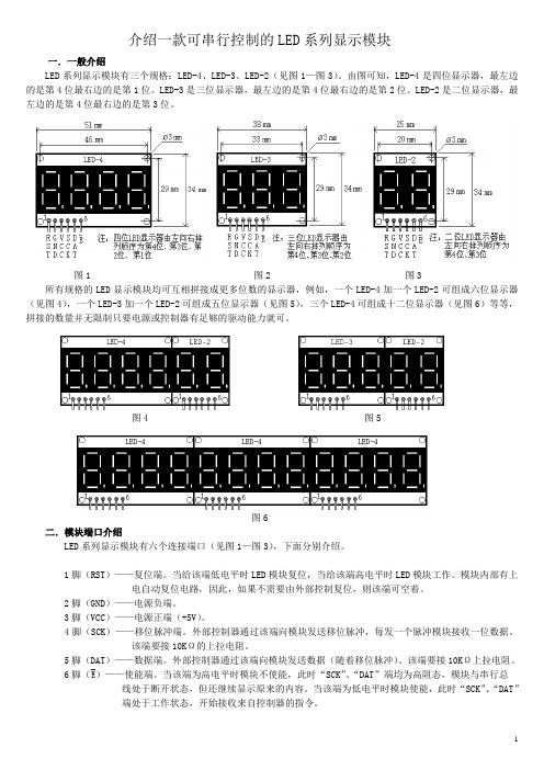
介绍一款可串行控制的LED系列显示模块一.一般介绍LED系列显示模块有三个规格:LED-4、LED-3、LED-2(见图1—图3)。
由图可知,LED-4是四位显示器,最左边的是第4位最右边的是第1位。
LED-3是三位显示器,最左边的是第4位最右边的是第2位。
LED-2是二位显示器,最左边的是第4位最右边的是第3位。
图1 图2 图3 所有规格的LED显示模块均可互相拼接成更多位数的显示器,例如,一个LED-4加一个LED-2可组成六位显示器(见图4),一个LED-3加一个LED-2可组成五位显示器(见图5),三个LED-4可组成十二位显示器(见图6)等等,拼接的数量并无限制只要电源或控制器有足够的驱动能力就可。
图4 图5图6二.模块端口介绍LED系列显示模块有六个连接端口(见图1—图3),下面分别介绍。
1脚(RST)——复位端。
当给该端低电平时LED模块复位,当给该端高电平时LED模块工作。
模块内部有上电自动复位电路,因此,如果不需要由外部控制复位,则该端可空着。
2脚(GND)——电源负端。
3脚(VCC)——电源正端(+5V)。
4脚(SCK)——移位脉冲端。
外部控制器通过该端向模块发送移位脉冲,每发一个脉冲模块接收一位数据。
该端要接10KΩ的上拉电阻。
5脚(DAT)——数据端。
外部控制器通过该端向模块发送数据(随着移位脉冲)。
该端要接10KΩ上拉电阻。
6脚()——使能端。
当该端为高电平时模块不使能,此时“SCK”、“DAT”端均为高阻态,模块与串行总线处于断开状态,但还继续显示原来的内容。
当该端为低电平时模块使能,此时“SCK”、“DAT”端处于工作状态,开始接收来自控制器的指令。
三.串行控制连接LED系列显示模块采用串行控制方式,只需三条信号线,可同各种单片机或控制器连接(见图7—图9)。
图7是用89C系列单片机与LED-3模块构成的000—999 计数显示电路。
首先外部计数脉冲通过T1端口输入到16位计数器T1中,然后将T1的内容进行BCD码变换,将变换后的数据通过P11口输出给LED-3显示。
变频器说明书
——————————————————————————————————————————————注意事项:为了避免触电危险,在对变频器进行任何操作之前确定母线电容的电压已经放尽。
测量电源端子排上DC-和DC+端子上的直流母线电压(参阅第1章电源端子描述)。
电压必须为零。
LED指示灯不亮并不表明电容器已经放电到安全电压等级。
注意事项:只有熟悉变频器和相关机器的合格技术人员才能操作系统的安装、启动和后续维护。
否则,可能导致人员伤害或设备损害。
注意事项:此变频器包含了ESD(静电放电)敏感零件和设备。
当安装、测试、维护或修理这些设备时,应设有静电控制预防措施。
如果不遵守ESD的控制措施,可能引起部件的损坏,参阅国家标准。
注意事项:任何不正确的使用或安装变频器可能会导致损害或降低其使用寿命。
任何接线或其它应用中出现的错误,例如电动机容量和变频器容量不匹配,交流输入电压不正确或不充足、周围环境温度过高可能导致系统的误操作。
注意事项:母线调节器功能对于防止过大减速、过分卸载和偏心负载而引起的过电压故障非常有用。
然而,它会引起以下情况中的一个:1.快速增加输入电压或不平衡的输入电压会引起不受控制的加速;2.实际减速时间可以比命令减速时间长然而,变频器在该状态下保持1分钟将产生“失速故障”。
如果该状态不被确认,母线调节器将被禁止。
另外,安装型号合适的动态制动电阻可以在大多数情况下提供等效或更高的效果。
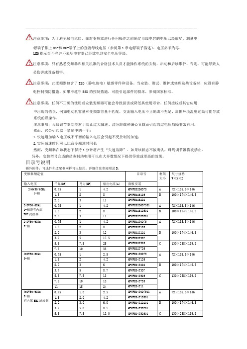
目录号说明本章提供HPVFE 变频器安装和接线的信息。
实际安装前,需要仔细阅读并理解本章介绍的所有信息。
规则,索肯和平(上海)电气概不承担责任。
如果在安装过程中忽视规则,将有可能导致人员伤害或设备损害。
打开机盖将机盖向外侧上方拉出,然后松手。
1-2安装/接线安装注意事项?将变频器垂直安装在光滑的平面上。
- 安装在35mmDIN导轨上(框架A 和框架B)。
或- 带螺丝安装。
表1• • 不要暴露于腐蚀性环境中。
• 远离潮湿及阳光直照。
控制模块做的时间控制器概要
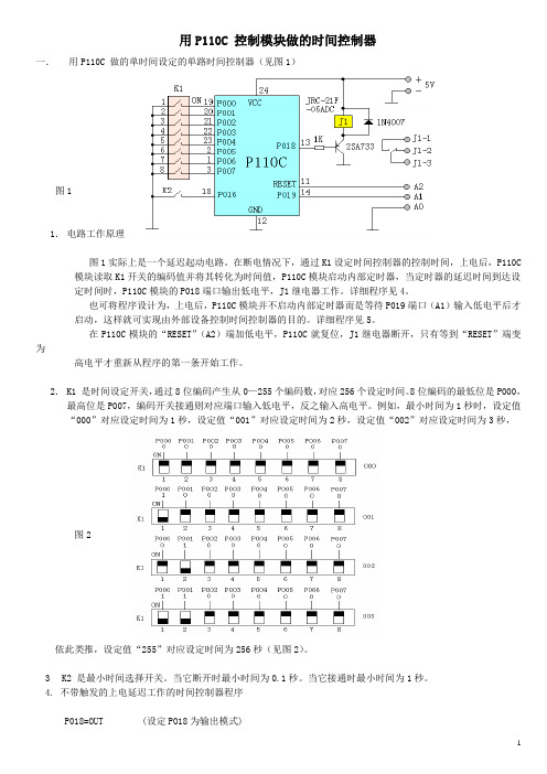
用P110C 控制模块做的时间控制器一.用P110C 做的单时间设定的单路时间控制器(见图1)图11.电路工作原理图1实际上是一个延迟起动电路。
在断电情况下,通过K1设定时间控制器的控制时间,上电后,P110C 模块读取K1开关的编码值并将其转化为时间值,P110C模块启动内部定时器,当定时器的延迟时间到达设定时间时,P110C模块的P018端口输出低电平,J1继电器工作。
详细程序见4。
也可将程序设计为,上电后,P110C模块并不启动内部定时器而是等待P019端口(A1)输入低电平后才启动,这样就可实现由外部设备控制时间控制器的目的。
详细程序见5。
在P110C模块的“RESET”(A2)端加低电平,P110C就复位,J1继电器断开,只有等到“RESET”端变为高电平才重新从程序的第一条开始工作。
2.K1 是时间设定开关,通过8位编码产生从0—255个编码数,对应256个设定时间。
8位编码的最低位是P000,最高位是P007,编码开关接通则对应端口输入低电平,反之输入高电平。
例如,最小时间为1秒时,设定值“000”对应设定时间为1秒,设定值“001”对应设定时间为2秒,设定值“002”对应设定时间为3秒,图2依此类推,设定值“255”对应设定时间为256秒(见图2)。
3K2 是最小时间选择开关。
当它断开时最小时间为0.1秒。
当它接通时最小时间为1秒。
4. 不带触发的上电延迟工作的时间控制器程序P018=OUT (设定PO18为输出模式)P018=1 (J1继电器不工作)P0=IN:1 (设定PO为带上拉电阻的输入模式)R0100=P0 (将延迟起动设定值读入到R0100中)P016=IN:1 (设定PO16为带上拉电阻的输入模式)P016==0,C01 (如果K2开关接通就跳转到C01处,否则执行下一步)C=ON:3 (激活延迟定时器时钟并设定最小时钟为1秒)LJMP,M1 (跳转到M1处)C01 C=ON:1 (激活延迟定时器时钟并设定最小时钟为0.1秒)M1 C0==R0100,M2 (激活定时器C0,如果C0延迟到由R0100设定的时间时就跳转到M2处,否则下一步) LJMP,M1 (跳转到M1处)M2 P018=0 (J1继电器工作)M0 LJMP,M0 (跳转到M0处)END (编程结束)5. 带触发的上电延迟工作的时间控制器程序P018=OUT (设定PO18为输出模式)P018=1 (J1继电器不工作)P0=IN:1 (设定PO为带上拉电阻的输入模式)R0100=P0 (将延迟设定值读入到R0100中)P016=IN:1 (设定PO16为带上拉电阻的输入模式)P019=IN:1 (设定PO19为带上拉电阻的输入模式)P016==0,C01 (如果K2开关接通就跳转到C01处,否则执行下一步)C=ON:3 (激活延迟定时器时钟并设定最小时钟为1秒)LJMP,M1 (跳转到M1处)C01 C=ON:1 (激活延迟定时器时钟并设定最小时钟为0.1秒)M1 P019==0,M3 (如果P019端有低电平触发就跳转到M3处,否则执行下一步)LJMP,M1 (跳转到M1处)M3 C0==R0100,M2 (激活定时器C0,如果C0延迟到由R0100设定的时间时就跳转到M2处,否则下一步) LJMP,M1 (跳转到M1处)M2 P018=0 (J1继电器工作)M0 LJMP,M0 (跳转到M0处)END (编程结束)二. 用P110C 做的双时间设定的单路时间控制器(见图3)图31.电路工作原理图3实际上是一个延迟起动延迟停止的时间控制电路。
TC01-CPP系列用户操作说明书-CN

所有的从机会被强制开启,主机关闭的时候所有的从机都会强制被关闭。
2. 从机单机开关:当机组处于联网模式时,从机在主机开启的条件下,才可开启和关闭本机。
注意:当“键盘开关机界面”的右上角显示为“U:01”时,手操器显示为主机的状态,此时
键盘开关机为整个网络开关机。当显示为“U:02”到“U:16”时,手操器显示为从机的状
1. 远控数字量输入功能未被启用或者启用时数字量输入处于开机模式。 2. 定时开关未被启用或者启用时当前时间处于开机时间内。 3. 未有严重报警出现。 4. 机组已被键盘开启。 5. 主机机组已开启(此功能只对从机有效) 注意:以上任一条件未被满足,机组将会关闭,机组状态则会显示机组关闭原因。键盘开关 机的优先级高于其他模式,当系统由于多个原因关机时,系统状态将首先显示键盘关机。
接地的金属物体,以释放人体所带静电。
(3) 注意CPP周围的通风和散热条件,切勿将导线头、铁屑等杂物通过通风窗落入机体
内
(4) 不得使用锋利物按键,以免损毁控制器。 (5) 不得扭曲或拉扯控制器的电线,以免损毁控制器,引致失灵。 (6) 不得试图以非本手册规定的方法打开设备。 (7) 不得使用腐蚀性化学品、溶剂或侵袭性清洁剂来清洁设备。 (8) 不得将产品用于非该技术手册规定的用途。 (9) 只有合格人员才可以安装本产品或者对本产品进行技术维护 (10) 阅读后,请将本技术手册妥善保存,以便随时取出参阅。同时,请将本手册交与其
等待 20 秒之后,自动跳转至“主界面” 图 3-1
3.2 主界面
图 3-2
图 3-3
界面显示:有设置油预热时间 等待油加热时间到之后,自动跳转至“主界 面”
显示系统进/出水温度 显示机组当前开关机状态 显示机组当前运行工况:制冷/制热 显示水泵,压缩机,风机的开关状态
C1101CCC控制说明
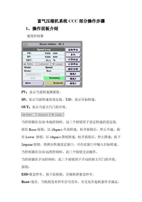
富气压缩机系统CCC部分操作步骤1、操作面板介绍速度控制器PV:显示当前转速测量值。
SP:显示当前转速的设定值,TSP:表示目标转速。
OUT:显示当前主汽门的开度。
当控制器在自动/本地控制时,这三个按钮用于设定转速的设定值,按住Raise按钮,以10rpm/s升高转速,松开按钮后,停止升速;按住Lower 按钮,以10rpm/s降低转速,松开按钮后,停止降速;按下Setpoint按钮,将弹出转速设定窗口,可在此窗口中输入目标转速。
当控制器在自动/远程控制时,此三个按钮无法操作。
当控制器在手动控制时,此三个按钮用于手动控制主汽门的开度。
按钮:ESD-紧急停车。
按下此按钮,压缩机将紧急停车。
Reset–复位。
当机组没有停车信号存在,并且允许起机条件全满足,按下此按钮后,控制模式将转变成Ready state(开机前先按次复位按钮,否则联锁系统无法正常)。
Start–正常启动。
当控制模式转变成Ready state后,按启动按钮,开始冲转,当转速达到最小转速300rpm后,控制器模式转变成accelerate mode,并升速到暖机1。
Idle 1–暖机1(1000rpm)。
Idle 2–暖机2(3000rpm)。
Idle 3–暖机3,本项目未用Rated–额定转速(6000rpm)。
Stop–正常停车。
当按下此按钮后,以20rpm/sec速率正常停车。
Remote/Local-远程/地方模式切换按钮。
地方模式:当转速在最小连续转速和最大连续转速之间时,转速设定值通过上述三个按钮设定;远程模式:当转速在最小连续转速和最大连续转速之间时,方可切换到此模式,转速设定值通过入口压力控制器设定。
Auto/Manual –自动/手动模式切换按钮。
自动模式:根据设定的转速自动控制主汽门的开度;手动模式:手动给定主汽门的开度。
(手动模式主要用于开机前的静态调试)。
状态指示灯:Warmup-暖启动:暖启动指示(未用);Running-运行:运行指示;当转速到达最小连续转速后,此指示灯亮。
P6100_P8100_P4100详细用户手册
iii
1/4 -DIN, 1/8 -DIN & 1/16 -DIN 控制器、显示仪和程序控制器手册
4.16 选件 A - RS485 通讯 ..................................................15
4.17 选件 A – 数字输入 .....................................................16
7.4 产品信息显示模式 .....................................................25
4.24 输出 2 – SSR 驱动.....................................................18
4.25 输出 2 – 固态继电器 ...................................................18
4.26 输出 2 – 线性直流 .....................................................19
4.21 输出 1 – 线性直流 .....................................................17
4.22 输出 2 - 继电器 ........................................................17
4.23 输出 2 – 双继电器 .....................................................18
5.1 上电步骤 .............................................................21
GP100-C3 使用说明书

第三章 设备的使用要求 一:设备的使用环境 -----------------------7 二:设备的供水----------------------------7 三:设备的供电----------------------------7 四:设备的接地----------------------------7 五:设备的遥控----------------------------7
第四章 设备的安装和调试 一:安装工作的准备和秩序 -----------------8 二:控制电路的试验------------------------9 三:灯丝电压的测试和调整 -----------------9 四:栅极截止负压的测量--------------------10 五:高压整流器的试验----------------------10
定的位置上。 4、装上淬火变压器,并接好汇流铜条。 5、接好两机柜之间的联线(单相不小于 70 平方,地连接不小于 16 平
方)和机柜上的高压线(高压线采用 30 角钢弯成 U 字型制作),要求高压线离地
第 8 页 共 20 页
8
GP100-C3 感应加热设备使用说明书
不低于 2.5 米。 6、将 FD-911S 电子管安装到水套上,灯丝和栅极暂不接上,并注意各
第 6 页 共 20 页
6
GP100-C3 感应加热设备使用说明书
第三章 设备的使用要求
一、设备的使用环境
1、环境温度在+5℃~ +40℃范围内。
2、防尘、防潮。
3、装有通风设备,排除淬火时产生的污浊气体。
二、设备的供水
1、总用水量:5000 公升/小时。
2、水压在 1.2~2 大气压之间。
广州周立功单片机 LPC1100系列微控制器 说明书

L P C1100系列微控制器第第十十六六章章模模数数转转换换器器用用户户手手册册R R e e v v11..0000地址:广州市天河北路689号光大银行大厦12楼F4网址:销售与服务网络广州周立功单片机发展有限公司地址:广州市天河北路689号光大银行大厦12楼F4 邮编:510630 电话:(020)38730972 38730976 38730916 38730917 38730977 传真:(020)38730925网址:广州专卖店地址:广州市天河区新赛格电子城203-204室电话:(020)87578634 87569917传真:(020)87578842南京周立功地址:南京市珠江路280号珠江大厦2006室电话:(025)83613221 83613271 83603500 传真:(025)83613271北京周立功地址:北京市海淀区知春路113号银网中心A座1207-1208室(中发电子市场斜对面)电话:(010)62536178 62536179 82628073传真:(010)82614433 重庆周立功地址:重庆市石桥铺科园一路二号大西洋国际大厦(赛格电子市场)1611室电话:(023)68796438 68796439传真:(023)68796439杭州周立功地址:杭州市天目山路217号江南电子大厦502室电话:(0571)28139611 28139612 2813961328139615 28139616 28139618传真:(0571)28139621 成都周立功地址:成都市一环路南二段1号数码同人港401室(磨子桥立交西北角)电话:(028)85439836 85437446传真:(028) 85437896深圳周立功地址:深圳市深南中路 2070号电子科技大厦C座4楼D室电话:(0755)83781788(5线)传真:(0755)83793285 武汉周立功地址:武汉市洪山区广埠屯珞瑜路158号12128室(华中电脑数码市场)电话:(027)87168497 87168297 87168397传真:(027)87163755上海周立功地址:上海市北京东路668号科技京城东座7E室电话:(021)53083452 53083453 53083496传真:(021)53083491西安办事处地址:西安市长安北路54号太平洋大厦1201室电话:(029)87881296 83063000 87881295传真:(029)87880865目录第16章 ADC (2)16.1 本章导读 (2)16.2 特性 (2)16.3 管脚描述 (2)16.4 时钟供应和功率控制 (2)16.5 寄存器描述 (2)16.5.1 A/D控制寄存器 (3)16.5.2 A/D全局数据寄存器 (5)16.5.3 A/D状态寄存器 (5)16.5.4 A/D中断使能寄存器 (5)16.5.5 A/D数据寄存器 (6)16.6 操作 (6)16.6.1 硬件触发转换 (6)16.6.2 中断 (6)16.6.3 精度和数字接收器 (6)第16章ADC 16.1 本章导读所有LPC1100系列ARM的ADC块都相同。
HK-P110DM 打印机说明书

HK-P110DM打印机使用说明书生产商有权修改说明书的内容而不做事先声明 !北京海信计算机有限公司目 录第一部分性能指标 (2)第二部分操作说明 (5)2.1 控制板外形尺寸及接插件位置说明 (5)2.2 并行接口 (5)2.3 钱箱接口 (7)2.4 按键和指示灯 (8)2.4.1自检方式 (8)2.4.2 LED指示说明 (8)2.4.3 在线/离线方式 (8)2.4.4 进纸方式 (8)2.5 关于黑标定位控制说明 (8)2.5.1 打印机构与打印控制固有相关参数 (8)2.5.2 黑标印刷注意事项 (8)2.5.3 黑标定位 (8)2.6 自动上纸 (9)2.7 打印机构接地说明 (10)第三部分打印控制命令 (11)3.1 概述 (11)3.2 命令详解 (11)3.2.1 字符控制命令 (11)3.2.2 打印位置控制命令 (15)3.2.3 点图命令 (17)3.2.4 汉字命令 (18)3.2.5 黑标控制命令 (20)3.2.6 其他命令 (22)3.3 切/撕纸位置偏移量和起始打印位置偏移量的设置 (23)3.3.1 设置值计算说明 (23)3.3.2 打印机构固有机械说明 (25)3.3.3 对于指定打印票样的黑标定位控制命令使用举例 (26)3.3.4 黑标定位控制使用注意事项 (31)第四部分使用注意事项 (32)第一部分 性能指标1. 采用EPSON M-U110(051)的针式打印机构和AU-110E切纸器(可选)2. 打印方法: 九针列式双向打印3. 打印密度: 210(全点)/420(半点)4. 有效打印宽度:35列(全点)/42列(半点)5. 打印速度: 约3.3行/秒(双向打印ASCⅡ字符)6. 走纸速度: 约100mm/秒7. 打印字符: IBM字符集II,7×7点,或5×7点国标汉字一、二级字库,15×16点字符说明:5×7点(W×H):全点打印,水平方向占6个全点。
S5PC110 用户手册
KIT-S5PC110 Use manualVer 1.0Date: 07-07-2010Boardcon Embedded designRev Date Description1.0 2010-07-07 The initial Released VersionIndexKIT-S5PC110 USE MANUAL (1)C HAPER I O VERVIEW (4)1.1 Introduction (4)1.2 Accessories (5)C HAPTER II H ARDWARE INFORMATION (7)2.1 Block diagram (7)2.2 CPU (7)2.3 MEMORY (10)2.4 Display (11)2.5 WIFI (12)2.6 Audio Codec (12)2.7 Power Supply (12)2.8 Accelerometer (12)2.9 Touch switch (Sound volume up/down) (12)C HAPTER III A NDROID S YSTEM D EVELOPMENT (14)3.1 Build Development environment (14)3.2 System Compiler (16)C HAPTER IV U PDATE THE IMAGE (18)Chaper I Overview1.1 IntroductionBoardcon KIT-S5PC110 Evaluation Board is a compact board using Samsung ARM Cortex-A8 S5PC110 microprocessor. It takes full features of this processor and supports 512MB Mobile DDR memory. The board has exposed many other hardware interfaces including RS232 serial port, LCD/TSP, HDMI, SD/MMC, TF-card interface, keyboard, WiFi, The board boot the system from SD card. It is able to support Android OS and provided the sourece code for the Linux2.6.29 BSP, Android 1.5-R3 and Android 2.1.Boardcon KIT-S5PC110 Evaluation Kit includes the KIT-S5PC110 evaluation board and all necessary accessories to help users start their design of multimedia applications. The board is preloaded with Android OS in SD card. User can display the subsystem using a 3.5" TFT LCD and Touch screen. Along with the kit, Boardcon provides user manual, schematic drawing and datasheet documents to help customers better understand and use the kit.Pic 1.1 KIT-S5PC110 evaluation board 1.2 AccessoriesThe accessories of the KIT-S5PC110 Evaluation Kit are as following: z 1 KIT-S5PC110 boardconz 1 Debug boardz 1 USB cablez 1 Batteryz 1 Schematics and the Android source codez2GB MicroSD cardz2GB SDHC CardPic 1.2 the accessoriesChapter II Hardware information2.1 Block diagramPic 2.1 Block diagram2.2 CPUS5PC110 is a 32-bit RISC cost-effective, low power, and high performance microprocessor solution for mobile phones and general applications. It integrates the ARM Cortex-A8 core, which implements the ARM architecture V7-A with supporting peripherals.To provide optimized Hardware (H/W) performance for the 3G and 3.5G communication services, S5PC110 adopts 64-bit internal bus architecture. This includes many powerful hardware accelerators for tasks such as motion video processing, display control, and scaling. Integrated Multi Format Codec (MFC) supports encoding and decoding of MPEG-1/2/4, H.263, and H.264, and decoding of VC1 and Divx. This hardware accelerator (MFC) supports real-time video conferencing and Analog TV out, HDMI for NTSC, and PAL mode. S5PC110 has an interface to external memory that is capable of sustaining heavy memory bandwidths required in high-end communication services. The memory system has Flash/ ROM external memory ports for parallel access and DRAM port to meet high bandwidths. DRAM controller supports LPDDR1 (mobile DDR), DDR2, or LPDDR2. Flash/ ROM port supports NAND Flash, NOR-Flash, OneNAND, SRAM, and ROM type external memory. To reduce the total system cost and enhance the overall functionality, S5PC110 includes many hardware peripherals such as TFT 24-bit true color LCD controller, Camera Interface, MIPI DSI, CSI-2, System Manager for power management, ATA interface, four UARTs, 24-channel DMA, four Timers, General I/O Ports, three I2S, S/PDIF, three IIC-BUS interface, two HS-SPI, USB Host 2.0, USB 2.0 OTG operating at high speed (480Mbps), four SD Host and high-speed Multimedia Card Interface, and four PLLs for clock generation.Features:• CortexA8 based CPU Subsystem with NEON, Samsung ARM Cortex-A8 S5PC110, up to 1GHz Operating Frequency• 32/32KB I/D Cache, 512KB L2 Cache• Operating System: Android2.1TM• Memory: ROM-2GB(TFLASH), RAM-512MB(Mobile DDR 400Mega data rate)• Storage & Expansion SlotStandard SD/SDHC card (up to 32GB)Standard• Connectivity: Bluetooth 2.0+EDR, WIFI IEEE 802.11b/g• Input and Output:3.5mm audio jackHDMI type-C ConnectorTTA-20 (USB, Charging, Line-out/in)• Audio: AAC,AAC+, MP3. Built-in speaker and microphone, standard 3.5mm headphone jack• Video: MP4, H.264. Standard type-C HDTV,supports 1080p via HDMI cable (H.264 +AAC based MP4 container format)• Display:3.5-Inch TFT-LCD capacitive touch320 x 480 (HVGA) resolution• Device Control4way DPAD8keys (Home, Menu, Back, Enter, A, B, X, Y)Capacitive Touch volume• BatteryDetachable Li-Ion battery 1300 mA• Sensor3-axis Accelerometer sensorGeo magnetic field sensor• WeightAbout 160g (with battery)• SizeAbout (LxWxT) 150 x 76 x 16 (mm)• 64-bit Multi-layer bus architecture• Advanced power management for mobile applications• ROM for secure booting and RAM for security function• 8-bit ITU 601/656 Camera Interface up to 8M pixel for scaled and 16M pixel for un-scaled resolution• Multi Format CODEC provides encoding and decoding of MPEG-4/H.263/H.264up to 30fps@HD(1080p) and decoding of MPEG-2/VC1/Divx/Xvid video up to 30ps@HD(1080p) • JPEG codec support up to 30Mpixels/s• 3D Graphics Acceleration with Programmable Shaderup to 10M triangles/s (Transform only) • 2D Graphics Acceleration with BitBlitand Rotation, up to 40Mpixels/s• 1/2/4/8 bpppalletized or 8/16/24bpp non-palletized Color-TFT support up to 2048x2048• TV-out for NTSC and PAL mode and HDMI 1.2 interface support with PHY• MIPI-HSI, MIPI-DSI and MIPI-CSI interface support• 1-channel AC-97 audio codec interface, 2-ch PCM serial audio interface, and 3-channel 24-bit I2Sinterface support (5.1ch support)• 2-channel S/PDIF interface support for digital audio• 2-channel I2C interface (up to 400KHz) support including 1-channel for HDMI• 3-channel HS-SPI, up to 52Mbps• 4-channel UART including 4Mbps port for Bluetooth 2.0 and IrDA port for SIR/MIR/FIR• On-chip USB 2.0 OTG supporting high speed (480Mbps, on-chip transceiver)• On-chip USB 1.1 Host supporting full speed (12Mbps, on-chip transceiver)• Asynchronous direct Modem Interface support including 16KB DPRAM• 3-channel SD/SDIO/HS-MMC interface support including CE-ATA• CF version 3.0 interface support for HDD• 24-channel DMA controller• Support 8x8 key matrix• 10-ch 12-bit multiplexed ADC• 2-ch CAN interface• Configurable GPIOs• Real time clock, PLL, timer with PWM and watch dog timer• SRAM/ROM/NOR/NAND Interface with x8 or x16 data bus• MuxedOneNANDInterface with x16 data bus• 1-port Mobile DDR Interface with x32 data bus (up to 333Mbps/pin DDR)• 1-port DDR2 interface with x16 or x32 data bus (333Mbps/pin DDR)• 1-port LPDDR2 interface (up to 333Mbps/pin DDR)2.3 MEMORY2.3.1 DDR2 512MBHynix DDR2 memory chips provide 512MB RAM which opens up a wide range of production and development opportunities. DDR2 memory consumes more power than MobileDDR. But, it is pretty much cost effective for huge memory space.You can choose memory vendor for example Samsung/Hynix/Elpida/Micron or others due to PC industry standard. DDR2 8Bit-bus-width memory is being used for PC/Notebook memory module. Each chip has 8-bit data-bus-width with 128MB. We mounted 4 chips to make 32bit data bus and total memory size is 512MB.2.3.2 2GB T-Flash(Micro-SD) CardTraditional memory (Like NOR-FLASH / NAND-FLASH) can't be found in KIT-S5PC110. KIT-S5PC110 has totally different booting method. KIT-S5PC110 implements direct T-Flash booting with excellent iROM feature of S5PC110.KIT-S5PC110 has 2Gbyte T-flash(removable) memory card for system area. Assume it has 3,862,528 blocks(sectors) and each block has 512bytes.Area Name Size in bytes From(sector #)To(Sector #)eFuse1K38625263862527U-boot B L1 8K38625103862525U-boot Environment variables16K38624783862509U-boot B L2 512K38614543862477ReservedLinux Kernel 4M38543363862527ReservedE XT3for Android system1GB02097152Note: Reserved area will be used for FW update and Recovery purpose.2.3.3 2GB SDHC CardAt this moment, Google Android supports only FAT32 file system. Other file system can be considered for big size 720p-HD contents. 2GB/4GB/8GB seems to be working well. But, 16GB memory card has some compatibility issues.2.3.4 Where is T-flash (Micro-SD)KIT-S5PC110 has 2 memory cards.z T-flash card contains boot-loader, kernel, Android system and applications.z SD card contains user files such as pictures, music, video clips and so on.Open the battery cover and you can find them.2.4 Display2.4.1 LCDz LMS350DF01-001 is a TMR(Transmissive with Micro Reflective) type color active matrix TFT (Thin Film Transistor) liquid crystal display (LCD) that uses amorphous silicon TFT as a switching devices.z This model is composed of a TFT- LCD module, a driver circuit and a back-light unit.z The resolution of a 3.5" contains 320 x 480 dots and can display up to 16,777,216 colors.2.4.2 Back-light driverDW8400 from DongWoon Anatech ()The DW8400 is a step-up DC/DC converter designed for driving up to 10 white LEDs in series from a single cell Lithium-Ion battery.2.4.3 Capacitive Touch screen controllerTouchCore 3.0 from CoreRiver.2.5 WIFIThis elegant combination from Fujitsu Component, based on Marvell's industry leading 88W8686 and CSR's BC4, brings both 802.11(b/g) to the KIT-S5PC110.If you want to use this module for your own product, contact Fujitsu first.z /en/contact/z Wireless Modules, Othersz Global Marketing 4 Division2.6 Audio CodecThe WM8991 is a highly integrated low power hi-fi CODEC from Wolfson. A powerful 1W speaker driver can operate in class D or AB modes. Stereo 24-bit sigma-delta ADCs and DACs provide hi-fi quality audio record and playback, with a flexible digital audio interface.2.7 Power Supply2.7.1 PMICPMIC MAX8698C supplies important power rails of S5PC110 and other devices. It contains 3 Step-down DC/DCs and 9 LODs.Unfortunately, the data sheet is not opened to public access because of Maxim's policy. We will discuss this issue with Maxim soon.2.7.2 DC/DC for Wireless deviceWifi-BT combo module consumes a lot of power and PMIC is not enough. So, KIT-S5PC110 takes additional high efficient DC/DC converter MAX1556 of Maxim.2.7.3 DC/DC for HDMI-5VoltHDMI needs 5Volt power rail. FAN5602 is a charge pump based step up/down DC/DC from Fairchild.2.7.4 Li+ Battery Fuel GaugeKIT-S5PC110 reads reliable battery level information from dedicated Li+ battery gauge Max17040 from Maxim.2.7.5 Li+ Battery ChargerThe XC6802 is a constant-current/constant-voltage linear charger IC for single cell lithium-ion batteries. Current source is USB-bus power.2.8 AccelerometerThe digital 3-axial acceleration sensor of Bosch Sensortec is included in KIT-S5PC110.2.9 Touch switch (Sound volume up/down)KIT-S5PC110 volume switches are implemented with touch sensitive IC TS01 fromAD-semiconductor.Chapter III Android System DevelopmentNote: Compile the Android system, please use the Ubuntu 9.04 version, the other version may be have some problem for compiling.3.1 Build Development environmentUsers in the use KIT-S5PC110 developed; they must first build a good ARM Linux cross-development environment. Below to ubuntu9.04 operating system as an example, cross-development environment to build.3.1.1 The installation of cross-compiling environmentInsert CD-ROM, ubuntu mount the CD-ROM to / media / cdrom directory, cross-compilation tool stored in the / media /cdrom/tools directory, the name for the cross-4.2.2-eabi.tar.bz2.Users ` the following command to install the cross compiler tools:# sudo mkdir /usr/local/arm# sudo tar xvjf cross-4.2.2-eabi.tar.bz2 –C /usr/local/arm# sudo tar xvjf 4.3.1-eabi.tar.gz –C /usr/local/arm3.1.2 Add Path in your environment fileModify your ~/.bashrc file to add a new path with editor (gedit or vi)PATH=$PATH:/usr/local/arm/4.2.2-eabi/usr/binTo apply this change login again or restart the .bashrc# source .bashrc3.1.3 Check whether tool-chain path set up is correct or not.# arm-linux-gcc -vUsing built-in specs.Target: arm-unknown-linux-gnueabiConfigured with:/home/scsuh/workplace/coffee/buildroot-20071011/toolchain_build_arm/gcc-4.2.2/config ure --prefix=/usr --build=i386-pc-linux-gnu --host=i386-pc-linux-gnu--target=arm-unknown-linux-gnueabi --enable-languages=c,c++--with-sysroot=/usr/local/arm/4.2.2-eabi/--with-build-time-tools=/usr/local/arm/4.2.2-eabi//usr/arm-unknown-linux-gnueabi/bin--disable-__cxa_atexit --enable-target-optspace --with-gnu-ld --enable-shared--with-gmp=/usr/local/arm/4.2.2-eabi//gmp --with-mpfr=/usr/local/arm/4.2.2-eabi//mpfr--disable-nls --enable-threads --disable-multilib --disable-largefile --with-arch=armv4t--with-float=soft --enable-cxx-flags=-msoft-floatThread model: posixgcc version 4.2.23.1.4 Download and Install essential packages for android1) Android requires the following system packages:z flex: This lexical analyzer generator is used to read a given input file for a description of a scanner to generate.z bison: This is a general-purpose parser generator.z gperf: This is a perfect hash function generator.z libesd0-dev: This enlightened sound daemon (dev files) is used to mix digitized audio streams for playback by a single device.z libwxgtk2.6-dev: This package provides GUI components and other facilities for many different platforms.z build-essential: This package contains a list of packages considered fundamental to building Debian packages.z Android source code includes a hard dependency on the Java Developer Kit (JDK) 5.0 Update 12 or greater.Download packages.# sudo apt-get install flex bison gperf libsdl-dev libesd0-dev libwxgtk2.6-devbuild-essential zip curl# sudo apt-get install valgrind2) Android also needs Phython 2.4 or higher. But, Ubuntu has Python 2.5 in general.3) Install JDK 5.0 Update12 or later.# sudo apt-get install sun-java6-jdk4) Add Path in your environment file. Modify your ~/.bashrc file to add a new path with editor (gedit or vi)export PATH=/home/$USER/bin:$PATHexport JAVA_HOME=/usr/lib/jvm/java-6-sun-1.6.0.16export ANDROID_JAVA_HOME=$JAVA_HOME5) To apply this change login again or restart the .bashrc# source .bashrcOptional!! If you meet compile error due to JDK version mismatching, add this items in to Synaptic package source. (sudo vi /etc/apt/sources.list)deb /ubuntu/ jaunty multiversedeb /ubuntu/ jaunty-updates multiversesudo apt-get updateAnd install old version JDK 5. and choose 1.5.0-sun in update-alternatives menu.sudo apt-get install sun-java5-jdksudo update-alternatives --config javasudo update-alternatives --config javacModify your ~/.bashrc file for JAVA_HOME environment variable. And, Apply it.export JAVA_HOME=/usr/lib/jvm/java-1.5.0-sun3.2 System Compiler3.2.1 Ready to build fileAll components of the system source code of the linux directory in the CD-ROM, the user before carrying out the development need to untar them to the linux system, such as:# mkdir ~/work# cd ~/work# tar xvzf /media/cdrom/linux/android.tar.gz# tar xvzf /media/cdrom/linux/linux.tar.gz# tar xvzf /media/cdrom/linux/uboot.tar.gzAfter you perform these operations, the current directory will be generated android, linux, uboot 4 directory.3.2.2 Compile the bootloader# cd ~/work/odroids_uboot# make mrproper# make hkdkc110_mmc_config# makeIf there is no error, u-boot.bin should be generated and file size is about 130~150Kbyte.3.2.3 linux kernel compilationTo start Kernel compile, .config file should be made first. You can make .config with below command.# cd ~/work/odroids_linux# make odroid_S_mmc_defconfigLet's start compile !# make zImageIf you can build kernel successfully, you will have "arch/arm/boot/zImage" (approximately 2Mbytes).3.2.4 Compile the Android file systemTo build the files, run make from within your working directory:# cd ~/work/odroids_android# ln -s vendor/sec/odroidt/build_android.sh ./odroidt_build.sh# ./build_android.sh•If there is no problem, you can see below message. rootfs directory is automatically generated and all root file system of Android is located in that directory.(odroidt-img folder)ok sucess !!!#•Note: Compile takes about 20 minutes with latest multi-core CPU based computer. Some old computer or virtual machine may need about 2 hours.Chapter IV Update the image4.1 update the android image to Micro SD in PCYou can write the raw image files with this special utility directly from XP PC to T-flash. The utilityKIT-S5PC110_TF_Burner_098a.exe is at the CD:/tools/ folder, if you want to update the image to micro SD, you should use it.z This utility is very useful when KIT-S5PC110 boot-loader is damaged or when you have new T-flash card.1) Remove T-flash card from KIT-S5PC110 and plug it in to Card Reader. If you don't have the card reader, buy it.This picture is just an example.2) Connect the card reader to PC.3) Check which drive is assigned for the card reader.4) Run ODROID_S_TF_Burner_21a.exe( this tools in the tools folder)5) Select drive of the card reader and Browse button near by android Image file and choose "odroids-20100622.odt"This file was in the tools folder. Such as the follow picture6) Click "START" button and writing process will be done quickly.Note) Do not change other parameters. Changing will cause malfunction.Where is T-flash (Micro-SD)KIT-S5PC110 has 2 memory cards.•T-flash card contains boot-loader, kernel, Android system and applications. •SD card contains user files such as pictures, music, video clips and so on.Open the battery cover and you can find them.4.2 update the image to Micro SD by usb device4.2.1 update the u-boot.bin fileUse Windows utility DNW.exe and USB driver (position: in tools folder)1) Connect Debug board and PC serial port with Serial Cable(1:1)2) Run serial communication software in PC (HyperTerminal/SecureCRT/etc)3) Configure serial port options (COM port, Baudrate : 115200, DATA : 8, STOP : 1, No-Parity, No Flow Control)4) Turn on Odroid and you can see the below booting message. Be sure to press any key quickly to stop the OS booting process.OKU-Boot 1.3.4-dirty (May 18 2010 - 23:33:57) for HKDKC110 D TypeCPU: S5PC110@1000MHz(OK)APLL = 1000MHz, HclkMsys = 200MHz, PclkMsys = 100MHzMPLL = 667MHz, EPLL = 80MHzHclkDsys = 166MHz, PclkDsys = 83MHzHclkPsys = 133MHz, PclkPsys = 66MHzSCLKA2M = 200MHzSerial = CLKUARTBoard: HKDKC110I2C: pres(1), div(3)readyDRAM: 256 MBFlash: 1 MBSD/MMC: 1886MBMuxed OneNAND 512MB 1.8V 16-bit (0x50)OneNAND version = 0x013e5) With "dnw" command, you can download any binary file to Odroid RAM from PC via USB.HKDKC110 # run dnwuInsert a OTG cable into the connector!6) If you plug in the USB Cable, you are ready to send binary files to board.Insert a OTG cable into the connector!OTG cable Connected!Now, Waiting for DNW to transmit data7) It's time to execute DNW utility. But, you should install the USB driver first. Driver installation is only required for the first time of USB connection. Driver file location should NOT be automatic selection. The driver was in the tools folder.8) Select the driver file and complete installation.9) Execute the DNW utility software. Ignore serial port settings, if you are familiar with other serial console software. Please also check for U SB:OK to make sure the connection is good.10) You can start the download with the menu for USB Port -> Download to select file to send.11) After downloading, the uboot will be download ok..4.2.1 update the kernel file1) Turn on Odroid and you can see the below booting message. Be sure to press any key quickly to stop the OS booting process.OKU-Boot 1.3.4-dirty (May 18 2010 - 23:33:57) for HKDKC110 D TypeCPU: S5PC110@1000MHz(OK)APLL = 1000MHz, HclkMsys = 200MHz, PclkMsys = 100MHzMPLL = 667MHz, EPLL = 80MHzHclkDsys = 166MHz, PclkDsys = 83MHzHclkPsys = 133MHz, PclkPsys = 66MHzSCLKA2M = 200MHzSerial = CLKUARTBoard: HKDKC110I2C: pres(1), div(3)readyDRAM: 256 MBFlash: 1 MBSD/MMC: 1886MBMuxed OneNAND 512MB 1.8V 16-bit (0x50)OneNAND version = 0x013e2) With "dnw" command, you can download any binary file to Odroid RAM from PC via USB.HKDKC110 # run dnwkInsert a OTG cable into the connector!3) If you plug in the USB Cable, you are ready to send binary files to board.Insert a OTG cable into the connector!OTG cable Connected!Now, Waiting for DNW to transmit data4) Execute the DNW utility software. Ignore serial port settings, if you are familiar with other serial console software. Please also check for U SB:OK to make sure the connection is good.5) You can start the download with the menu for USB Port -> Download to select file to send.5) After downloading, the zImage will be download ok..4.3 update the Android image to Micro SD<Method > update the rootfs that you Compiled to Micro SD1) Insert the T-Flash in to Card reader and connect the card reader to Linux PC.2) Copy all files in the odroidt-img/system/ to EXT3 partition of T-Flash.3) Normally when you plug the Card reader into Ubuntu PC, Ubuntu will mount it automatically. Youneed to remember the mounting point.4) To find the mounting points, perform below commands.# mount/dev/sdc1 on /media/disk-1 type ext3 (rw,nosuid,nodev,uhelper=hal) ---> MountT-Flash first partition(Android system): remember this!/dev/sdc2 on /media/disk-2 type ext3 (rw,nosuid,nodev,uhelper=hal) ---> MountT-Flash second partition(Android data)4.3.1 Copy rootfs to already formatted partition (Overwrite)•Copy root file system to EXT3 partition of T-Flash.•# sudo cp -a ~/work/odroidt-img/system/* /media/disk-1 ---> mounting point (You may have different location)•# sync•Unmount the T-Flash disk and move the card from PC to KIT-S%PC110 for testing.•# sudo umount /media/disk-1 (or) sudo umount /dev/sdc1 ---> Unmount T-Flash first partition(Android system)•# sudo umount /media/disk-2 (or) sudo umount /dev/sdc2 ---> Unmount T-Flash second partition(Android data)4.3.2 Copy android system to new partition (Clean & Write)•Before copying files, format the partition first. All data will be erased.•To format the T-Flash, unmount it first.•This is an example when device node of T-flash is /dev/sdc.# sudo umount /dev/sdc1 ---> Unmount T-Flash first partition(Android system)# sudo umount /dev/sdc2 ---> Unmount T-Flash second partition(Android data)# sudo mkfs.ext3 /dev/sdc1•If you want clean install, erase the Android data partition as below.•WARNING! : You can delete all of data in you Host PC, if you select wrong disk/partition node name.# sudo mkfs.ext3 /dev/sdc2 ---> T-Flash second partition(Android data)•After formatting, mount the T-flash to /media/disk# sudo mount /dev/sdc1 /media/disk ---> T-Flash first partition(Android system)•You can copy the android system files to T-Flash.# sudo cp -a ~/mydroid/android/odroidt-img/system/* /media/disk ---> T-Flash first partition(Android system)# sync•Unmount the T-Flash disk and move the card from PC to Odroid for testing.# sudo umount /media/disk (or) sudo umount /dev/sdc1 ---> Unmount T-Flash second partition(Android system)。
Procontrol P13系统输入模块详细说明说明书
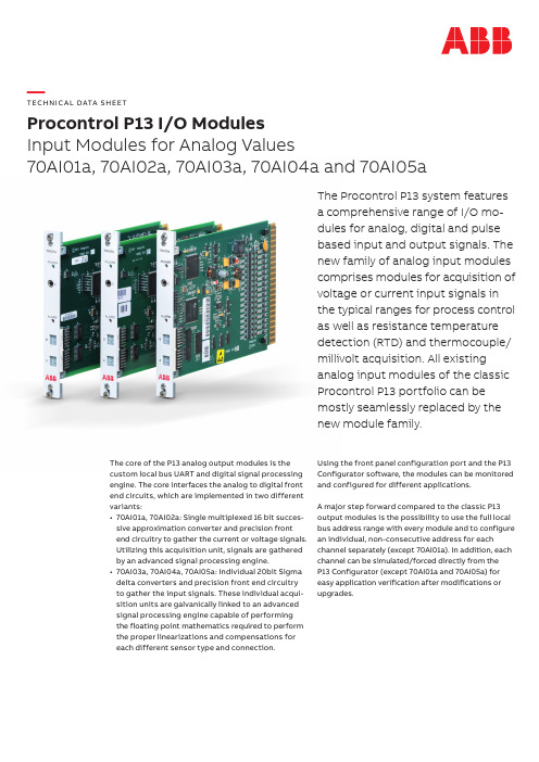
The Procontrol P13 system features a comprehensive range of I/O mo-dules for analog, digital and pulse based input and output signals. The new family of analog input modules comprises modules for acquisition of voltage or current input signals in the typical ranges for process control as well as resistance temperature detection (RTD) and thermocouple/ millivolt acquisition. All existing analog input modules of the classic Procontrol P13 portfolio can be mostly seamlessly replaced by the new module family.The core of the P13 analog output modules is the custom local bus UART and digital signal processing engine. The core interfaces the analog to digital front end circuits, which are implemented in two different variants:• 70AI01a, 70AI02a: Single multiplexed 16 bit succes-sive approximation converter and precision front end circuitry to gather the current or voltage signals. Utilizing this acquisition unit, signals are gathered by an advanced signal processing engine.• 70AI03a, 70AI04a, 70AI05a: Individual 20bit Sigma delta converters and precision front end circuitry to gather the input signals. These individual acqui- sition units are galvanically linked to an advanced signal processing engine capable of performing the floating point mathematics required to perform the proper linearizations and compensations for each different sensor type and ing the front panel configuration port and the P13 Configurator software, the modules can be monitored and configured for different applications.A major step forward compared to the classic P13 output modules is the possibility to use the full local bus address range with every module and to configure an individual, non-consecutive address for each channel separately (except 70AI01a). In addition, each channel can be simulated/forced directly from theP13 Configurator (except 70AI01a and 70AI05a) for easy application verification after modifications or upgrades.—TECH N I C A L DATA S H EE TProcontrol P13 I/O ModulesInput Modules for Analog Values70AI01a, 70AI02a, 70AI03a, 70AI04a and 70AI05a—Technical DataProcontrol P13 I/O ModulesFeature Highlights• Comprehensive family of analog input modules for all power generation applications• Flexible configuration possibilities for one-to-one re-placements, retrofits and extensions• Complete parametrization and configuration in software with the P13 Configurator tool; no need to set code switches and jumpers manually• Support of non-consecutive addressing of input channels (except 70AI01a)• Support for forcing/simulating individual input channels (except 70AI01a and 70AI05a)• Support for disabling of individual input channels and less waste of valuable local bus addresses• All modules can use the complete local bus address (normal and special) in arbitrary combinations on a single module• State-of-the-art technology (DSP /FPGA-based) for low maintenance and outmost durability• New high-density 16 channel input module for chal-lenging retrofits with tight rack space constraints • Support for individual forcing of input values and/or channel disturbance on card level with the P13 Configurator tool (except 70AI01a)• Configuration cables are available with serial (DB9) or USB plug70AI01a70AI02a70AI03a 70AI04a70AI05aDescription Analog input module, voltage/currentAnalog input module, voltage/currentAnalog input module, RTDAnalog input module, isolated thermocouple/voltageAnalog input module, isolated voltage/current Predecessor Module(s)70EA01, 70EA02, 70EA06(70EA01, 70EA02, 70EA06)70EA0370EA04, 70EA05(70EA01, 70EA02, 70EA06)I/O Interface No. of Channels 4 (four)16 (sixteen)4 (four)8 (eight)6 (six)Input Types+/-10VDC, +/-20mA, 4..20mARTD (Pt100)Thermocouple (E, J, K, N, S and T), +/- 50mV, +/- 100mV +/-10VDC, +/-20mA, 4..20mAInputCharacteristicsPlatinum 100 385 (-200 to +650°C)E (-270 to 1000°C)J (-210 to 760°C)K (-270 to 1372°C)N (-270 to 1300°C)S (-50 to 1768.1°C)T (-270 to 1000°C)Connection Types Single Ended, Differential 2, 3, 4-wireSingle Ended, DifferentialResolution 16 bits internal, 15 bits local bus 20 bits internal, 15 bits local bus Conversion Type Single multiplexed 16bit successive approximation Individual 20bit sigma deltaConversion Time/ Acquisition Rate2500Hz2500Hz35ms, 68ms, 135ms, 268ms, 534ms (configurable)Fast: 60Hz Slow: 15Hz (configurable)8ms, 17ms, 33ms, 67ms, 133ms (configurable)Accuracy 0.1% typical+/- 0.1°C typicalConverter voltage:0.0015% typical Temperature:< 0.5°C typical0.0015% typical at slowest conversion timeCommon Mode RejectionTyp. = 90db1k source imbalance dc – 60Hz120db @50/60Hz and @DC70AI01a70AI02a70AI03a70AI04a70AI05a Local Bus InterfaceChannel Addressing (on local bus)4 addresses,normal/specialrange, consecutive16 addresses,normal/special range,non-consecutive4 addresses,normal/special range,non-consecutive8 addresses,normal/special range,non-consecutive6 addresses,normal/special range,non-consecutiveChannel Usage Individual enabling/disabling per channelOutput Format+/- 200%+/- 2000°C+/- 200%Update Rate for all Channels (on local bus)5ms5ms40ms (dependingon conversion time)20ms10ms (dependingon conversion time)Configuration and MaintenanceConfigurationInterfaceFront panel RS232 (custom phone jack)ConfigurationMemoryEEPROM (onboard)Simulation Functions Individual forcing of channels Fault Detection, Annunciation and BehaviorFault Inputs (Optional)Four individual digital fault inputs (+24Vdc) (one per channel)Fault Conditions A/D converter failure conditions,loop power supply errors andcommunications errorsA/D converterfailure conditions,communicationserrors, temperaturerange errors, CJCrange errorsThermocouplebreak, A/Dconverter failureconditions,communicationserrors, temperaturerange errors, CJCrange errorsA/D converterfailure conditions,loop power supplyerrors andcommunicationserrorsFault AnnunciationVisual Master module ALARM LED, Individual channel ALARM LEDs I/O SME1 Digital alarm output (+24Vdc)Local Bus Disturbance bit on local bus address wordsFault Behavior Input set to “0”Input set to “0” or“Last known goodvalue” (configurableper channel)Electrical CharacteristicsPower Supply via P13 rackMin OperatingVoltage+19.5VdcMax OperatingVoltage+30VdcPower Consumption 2.1W typical5.3W maxSurge voltageresistance1500VChannel toChannel1000VrmsChannel toGround1000VrmsChannel toLogic1000Vrms150Vdc in Voltage Mode15Vdc240Vdc/Vac inVoltage Mode Max. Input inCurrent Mode45mA40mA50mA2V A A 007640 e n r e v A - 17 A p r i l 2020—solutions.abb/controlsystems—We reserve the right to make technical changes to the products or modify the contents of this document without prior notice. With regard to purchase orders,the agreed particulars shall prevail.ABB does not assume any responsibility for any errors or incomplete information in this document.We reserve all rights to this document and the items and images it contains. The reproduction, disclosure to third parties or the use of the content of this document –including parts thereof – are prohibited without ABB’s prior written permission Copyright© 2020 ABB All rights reserved70AI01a70AI02a 70AI03a 70AI04a70AI05aOther Module Specific DataRemark: Minor changes in edge connector layout compared to 70EA01.RTD Excitation Voltage: 2.5Vdc RTD Excitation Current: 0.3mA @100ΩMaximum Lead Length: @250°C, using 0.5mm2 wire: 1220mCJC Operating Temp: -20 to 60°C Thermocouple Break: UpscaleDigital Filters:0ms, 250ms, 500ms, 1s, 2s, 3sAmbient Conditions and General Properties Operating Temperature 0 – 60°C Relative Humidity 0 – 95%CertificationsCE, IEC 61508:2010 & IEC 61511:2004 (up to SIL3)CE DimensionsP13 Standard module (3.5E, 1T)。
CP 110型号差压传感器数据表说明书
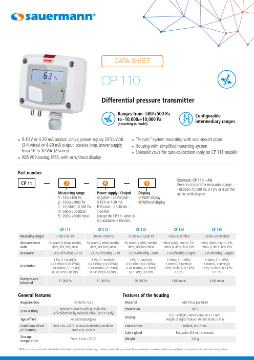
•0-10 V or 4-20 mA output, active, power supply 24 Vac/Vdc(3-4 wires) or 4-20 mA output, passive loop, power supplyfrom 16 to 30 Vdc (2 wires)• ABS V0 housing, IP65, with or without display• “¼ turn” system mounting with wall-mount plate• Housing with simplified mounting system• Solenoid valve for auto-calibration (only on CP 111 model)Configurableintermediary rangesRanges from -500/+500 Pato -10,000/+10,000 Pa(according to model)Part numberExample: CP 113 – AOPressure transmitter measuring range-10,000/+10,000 Pa, 0-10 V or 4-20 mAactive, with displayMeasuring range1: -100/+100 Pa2: -1000/+1000 Pa3: -10,000/+10,000 Pa4: -500/+500 mbar5: -2000/+2000 mbarPower supply / OutputA: Active – 24 Vac/Vdc –0-10 V or 4-20 mAP: Passive – 16/30 Vdc –4-20 mA(except the CP 111 which isnot available in Passive).O: With displayN: Without display*All the accuracies indicated in this technical datasheet were stated in laboratory conditions, and can be guaranteed for measurements carried out in the same conditions, or carried out with calibration compensation.Features of the housingGeneral featuresConnectionsOutput / Supply(power supply 24 Vac/Vdc ±10%), 3-4 wiresPassive loop 4-20 mA (power supply 16/30 Vdc), 2 wiresTechnical specificationsInside the front housing 2CP 112, CP 1132341. Solenoid valve (CP 111 only)2. Left DIP switch3. Right DIP switch4. Pressure connections5. Safety pressure connections6. Autozero7. LCC-S software connection8. Output terminal block9. Power supply terminal block 10. Cable glandRemovable front face Fixed back housing671098123F T _E N – C P 110 – 14/01/2021 – N o n -c o n t r a c t u a l d o c u m e n t – W e r e s e r v e t h e r i g h t t o m o d i f y t h e c h a r a c te ri s t i c s o f o u r p r o d u c t s w i t h o u t p r i o r n o t i c e .Only the accessories supplied with the device must be used.are supplied).installed.Maintenance: please avoid any aggressive solvent. Please protect the transmitter and its probes from any cleaning product containing formalin, that may be used for cleaning rooms or ducts.MountingCP 1113442CP 114, CP 115352Settings and use of the transmitterAuto-calibrationCP 111 pressure transmitter has a temperature compensation of the gain from 0 to 50 °C and an auto-calibration process that guarantees over the time an excellent stability and a perfect reliability of the measurement on low and high ranges.ConfigurationThe configuration of the parameters can be done either with the DIP switch or via software (you cannot combine both solutions). To configure the transmitter , unscrew the 4 screws from the housing then open it. DIP switches allowing the different settings are then accessible.T o configure the transmitter , it must not be energized. Then, you can make the settings required, with the DIP switches (as shown on the drawing below). When the transmitter is configured, you can power it up.12341234Left DIP switchRight DIP switchMeasuring ranges setting Output settingStandard range or central 0 settingUnits settingOn-off switchRefer to the user manual of the LCC-S to make the configuration.For detailed combinations of DIP switches, refer to the CP 110 Quick Start Guide.WarrantyInstruments have 1-year guarantee for any manufacturing defect.。
HP Omni Pro 110 AIO PC说明书

Illustrated Parts & Service MapHP Omni Pro 110 All-in-One PC© 2011, 2012 Hewlett-Packard Development Company, L.P . The informationcontained herein is subject to change without notice. HP shall not be liable for technical or editorial errors or omissions contained herein. Intel, Pentium, Intel Inside, and the Intel logo are trademarks or registered trademarks of the Intel Corporation and its subsidiaries in the U. S. and other countries.Document Number 654195-002. 2nd Edition October 2012.Key SpecificationsSpare PartsProcessor Type Intel® Celeron Dual-Core, Intel Pentium Dual-Core, IntelCore™2 DuoRAM TypePC3-10600 DDR3 1333-MHz non-ECC SDRAM Maximum RAM Sup-ported 4 GB Display•20-inch diagonal•Resolution: 1600 x 900•Contrast Ratio: 1000:1•Image brightness: 250 nits •Typical response time: 5msGraphics Adapter Integrated Intel Graphics Media Accelerator X4500Chipset Intel G41 Express chipsetExpansionBays:External: (1) 5.25- Slim Tray drive bay Internal: (1) 3.5-inch drive bay Slots:(1) Mini Socket Slot (Occupied)I/O Interfaces(6) USB 2.0 ports: (2) left slide, (4) rear; (1) RJ-45, (1) left side audio headphone, (1) left side microphone, (1) rear line out Operating Systems•Windows 7 Professional 32 & 64•Windows 7 Home Basic 64•Windows 7 Starter Edition 32•RedFlag Linux •FreeDOSMass Storage Devices (not illustrated)8X DVD±RW SuperMulti DL Drive with LightScribe 597927-001Optical drive bracket (mounts on back of optical drive)651600-001Optical drive bezel 651599-0011 TB hard drive 621418-001750 GB hard drive 632938-001500 GB hard drive 621421-001320 GB hard drive 621420-001250 GB hard drive621419-001Standard and Optional BoardsSystem boards with thermal grease, alcohol pad, and CPU socket cover 1System board 648965-0012Power button board 651585-0013Inverter board 651601-0014Webcam module651586-0015WLAN module (802.11b/g/n) (1x1 mini card)634906-001Memory modules (PC3-10600)*2 GB 651609-001*1 GB651608-001Intel Core2 Duo processors with thermal material:E8500, 6-MB cache, 3.16 GHz 466170-001E8400, 6-MB cache, 3.00 GHz 509554-001E7600, 3-MB cache, 3.06 GHz573954-001E7500, 3-MB cache, 2.93 GHz586745-001Intel Pentium processors with thermal material:E6800, 2-MB cache, 3.20 GHz, 1066-MHz FSB631758-001E6700, 2-MB cache, 3.20 GHz, 1066-MHz FSB 617840-001E5800, 2-MB cache, 3.30 GHz, 800-MHz FSB 646376-001E5700, 2-MB cache, 3.00 GHz, 800-MHz FSB 631759-001E5500, 2-MB cache, 2.80 GHz, 800-MHz FSB 613035-001Intel Celeron processor with thermal material:E3500, 1-MB cache, 2.70 GHz, 800-MHz FSB 633219-001* Not shownMiscellaneous Parts 1Display panel, 20-inch, non-glare 646794-0012Display bezel704214-0013Heat sink (thermal module)651607-0014Speaker, right 651597-0014Speaker, left 651598-0015Fan651606-001*Thermal pad, DIMM, 20mm x 50mm x 2.5mm (mount under PCA)651595-001*Thermal pad, VRM, 15mm x 40mm x 4mm (mount under PCA)651596-001*AC adapter, 150W, external 651587-001*Mouse, USB, optical, Portia621416-001*Not shownSystem BoardComputer Setup.Cables1WLAN antenna cable651594-001 2Inverter cable651588-001 3Optical drive cable651590-001 4LVDS cable651589-001 5Hard drive cable651592-001 6Power button/LED cable651593-001 7Webcam cable651591-001 *Not shownSystem Board Connectors and Jumpers (component location may vary)MINI _CARD1Mini card connector (WLAN)LAN Network connector LVDS_UMA Display connector DC JACK AC adapter connector PROCESSOR CPU SPEAKER_L Left speaker connector BAT2RTC battery socket SPEAKER_R Right speaker connectorCHANNELA _DIMM0Memory socket 1SATA_HDDPOWERHard drive power connec-torCHANNELB_DIMM0Memory socket 2SATA0Hard drive connector 1394A1394 port SATA1Optical drive connectorUSB2USB connector SATA_ODDPOWER Optical drive power con-nectorUSB1USB connector SYSTEM FAN System fan connector MIC Microphone connector PWR_CON1Power cable connector HP_OUT Headphone jack WEBCAM Webcam connector USB3-6USB connectors INVERTER Inverter board connector LINE_OUT Headphone connector Computer Setup MenuHeading Option / DescriptionMain System Time Allows you to set system time.System Date Allows you to set system date.System IDs(view only) Lists product name, serial numberUUID, SKU number, family name, feature byte,build ID.Language Allows you to select the language.Floppy Diskette A Specifies capacity and physical size, if installed.1st Drive2nd DriveAllow you to: enable/disable port configuration,view capacity (HDD only), view transfer mode. Alsoallows you to run HDD self-test for selected chan-nel: SMART status check, SMART short self test,SMART extended self test.System Information Allows you to view installed memory, memorybanks 1-2, BIOS revision, core version. Advanced CPU Type View only.CPU Speed View only.Cache RAM View only.Supervisor Pass-wordAllows you to view the supervisor password.User Password Allows you to view the user password.Onboard LAN Disable/enable onboard LAN controller.Onboard WLAN Disable/enable onboard WLAN controller.Onboard LAN BootROMDisable/enable the boot ROM of the onboard LANchip.Onboard 1394Allows you to enable/disable all 1394 ports.Primary VideoAdapterAllows you to select boot display device whenmore than 2 video options are offered by system:Integrated (onboard), PCIe.SATA Controller Allows you to disable/enable the SATA controller.SATA ControllerModeIf SATA controller is enabled, allows you to set themode to: IDE, AHCI.Onboard Audio Auto/disable/enable.USB Ports Allows you to individually enable/disable availableUSB ports.Change SupervisorPasswordAllows you to change the supervisor password.Power After AC PowerFailureAllows you to select system restart behavior afterpower loss: Stay off, Power on, Auto.XD (Execute Dis-able)Disable/enable XD bit.Virtualization Tech-nologyDisable/enable.WOL from S5Allows you to enable/disable Limited (normal shut-down) WOL from S5 support.Boot Boot-time Diagnos-tic ScreenDisable/enable POST diagnostic messages dis-play.ESC: Boot Menu Enables/disables the ability to press the Esc key toaccess the boot menu during boot.F9: Diagnostics Enables/disables the ability to press the F9 key toaccess the Diagnostics menu during boot.F10: Setup Enables/disables the ability to press the F10 key toaccess the Setup menu during boot.F11: Recovery Enables/disables the ability to press the F11 key toaccess the recovery menu during boot.F12: Boot from LAN Enables/disables the ability to press the F12 key toboot from LAN.Boot Device Prior-ity: 1st Boot Device,2nd Boot Device,3rd Boot Device,4th Boot DeviceAllows you to specify which device groups will bootfirst, second, third, and fourth or to disable anyof the four: Floppy group, CD-ROM group, Harddrive group, Network boot group. MS-DOS drivelettering assignments maybe apply after a non-MS-DOS operating system has started.Floppy Group BootPrioritySpecifies boot device priority within removabledevices.CD-ROM Boot Pri-oritySpecifies boot device priority within CD/DVDdrives.Hard Drive Boot Pri-oritySpecifies boot device priority within hard drives.Network GroupBoot PrioritySpecifies boot device priority within bootable net-work devices.Exit Exit SavingChangesPress Enter to exit saving changes.Exit DiscardingChangesPress Enter to exit discarding changes.Load SetupDefaultsPress Enter to load setup defaults.Discard Changes Press Enter to discard changes.Save Changes Press Enter to save changes.。
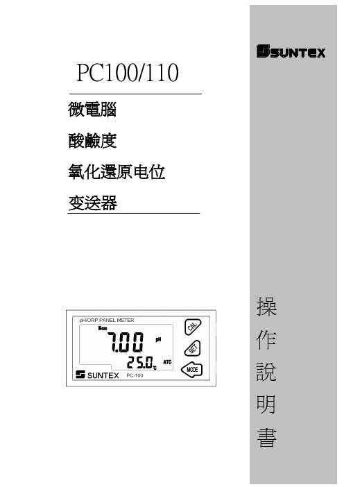
PC100(110)操作手册-090604
注意:1. 本公司電極專用延長線料號為 7202-F94009-BK 和 7202-RG-58. 1.)未使用溫度探棒時,專用電極線料號為 7202-RG-58 2.)使用溫度探棒時,專用電極線料號為 7202-F94009-BK 2. 使用 8-26-3(NTC30K)或 8-26-8(PT1000)溫度探棒做兩線接法時,黑色出線 端禁用。 [二] 三線式電極配線法 IN 端接點 電極線之中心軸線 接地棒 電極線之網線 溫度探棒之紅線 溫度探棒之綠線 備用腳 接點號碼 1 2 3 4 5 6、7 OUT 端接點 電極專用延長線之中心軸線 GND 電極專用延長線之綠線 電極專用延長線之紅線 電極專用延長線之網線 備用腳 主機端接點 GLASS SG REF T/P T/P ----
示後,同時放開所有按鍵,即可恢復原廠參數預設值。 原廠預設值: 測量模式:pH 溫度補償:NTC 警報:HI(PC110 only) PH 測量時:SP1= 7.00 pH,db1= 0.10 pH ORP 測量時:SP1=600mV, db1= 10 mV 二次儀錶時:SP1=1200 mV, db1= 10 mV pH/ORP 電流輸出:4~20 mA,2.00~12.00pH TP 電流輸出:4~20 mA, 0~100.0℃ 5.4.2 校正參數重置: 於測量模式下,同時按下 鍵不放,看到螢幕上出現 init + 顯示後,同時放開所有按鍵,即可恢復原廠校正預設值。 原廠預設值: OS 值:0 mV SLOPE 值:100.0 % 校正模式:單點或二點:CA1,Ct1, Cn1
9
3.4 電極配線參考圖: 二線式配線法
pH/ ORP
SG REF. GLASS SG
三線式配線法
pH/ ORP
REF. GLASS
P110C控制模块的应用(2)—用P110C制作时间控制器

P110C控制模块的应用(2)—用P110C制作时间控制器杨阳
【期刊名称】《电子制作》
【年(卷),期】2008(000)001
【摘要】三、用P110C制作单时间设定的单路时间控制器1.电路工作原理电路见图19。
图19实际上是一个延迟启动电路。
在断电状态下,通过K1设定时间控制器的控制时间。
上电后,P110C模块读取开关K1的编码值并将其转化为时间值,然后启动内部定时器。
当定时器的延迟时间到达设定时间时,从P110C模块的P018端口输出低电平,继电器J1工作。
【总页数】5页(P29-33)
【作者】杨阳
【作者单位】无
【正文语种】中文
【中图分类】TP273
【相关文献】
1.P110C控制模块的应用(3)——可连级时间控制器制作 [J], 杨阳
2.P110C控制模块的应用(4) [J], 杨阳
3.P110C控制模块的应用(5) [J], 杨阳
4.P110C可编程控制模块的应用(1)——基本介绍 [J], 柏青
5.BRIGHT系列紧凑型质量流量和压力\r计/控制器本地读取/控制模块 [J],
因版权原因,仅展示原文概要,查看原文内容请购买。
- 1、下载文档前请自行甄别文档内容的完整性,平台不提供额外的编辑、内容补充、找答案等附加服务。
- 2、"仅部分预览"的文档,不可在线预览部分如存在完整性等问题,可反馈申请退款(可完整预览的文档不适用该条件!)。
- 3、如文档侵犯您的权益,请联系客服反馈,我们会尽快为您处理(人工客服工作时间:9:00-18:30)。
P110C 控制模块使用说明书一.一般介绍图1图2图3图41.由图1、图2可见P110C几乎每一个端口都是多功能的,用户可通过编程选用其中任何一项功能。
2. P110C可在2.4V-5.5V供电电压下工作,它自身的耗电可由用户通过编程设定(有4挡功耗模式选择)在0.5微安(μA)—3.5毫安(mA)之间,因此,即便是用电池供电也可长期稳定工作。
3. P110C 可在 -40℃— +75℃环境温度下长期稳定工作。
4.由图3可见P110C的外型尺寸为标准24脚DIP封装集成电路形式,因此,它可同标准插座配合。
5. 图4描述了P110C-B 的外观尺寸。
P110C-B就是带印刷电路板的P110C(它上面插了一个P110C模块),印刷电路板上接线端的排列与P110C管脚一一对应。
不想自己制做印刷电路板的用户可选用P110C-B。
二.P110C可编程控制模块外部端口介绍1.有二十个通用输出/输入(I/O)端口(P000---P019),每个端口即可做输入也可做输出。
在做输出时每个端口可输出至少10毫安(mA)电流(不论是高电平输出还是低电平输出),因此每个端口都可单独驱动LED发光二极管或光电耦合器。
2.有一路模拟比较输入端口(AN+/AN-)。
3.有七个模/数转换(ADC)输入端口(ADC0---ADC6),每个都具有10位的分辩精度,转换时间52微秒(μS),模拟参考电压为VCC 。
4.有六个脉冲宽度调制(PWM)输出端口(PWM0---PWM5),每路的输出脉冲宽度均可在0%--100%之间调整,脉冲输出极性可正向也可反向,脉冲输出频率可在15HZ—15KHZ之间调整,利用上述特性,可同时控制三台直流电动机的调速运行,或实现三路数/模转换(DAC)输出。
5.有三个频率输出端口(FRE0-FRE2),每路的输出频率均可在1HZ—15.686KHZ 间调整,可同时控制三台步进电机的调速运行,或实现三路频率输出。
6.有一路异步串行通讯口(RXD/TXD),波特率可设定,可实现与计算机及其它外设的通讯。
7.有一路可兼容I2C标准的的二线通讯口(SDA/SCL),可实现与任何带有I2C 接口的外设的通讯。
8.有一路音乐输出口,可输出用户编制的音乐。
9.有二路高速计数器脉冲输入端口(T0/T1)。
10.有20个外部中断源(INT000-INT019),即:每一个通用I/O端口都具有外部事件中断功能。
除此之外,异步串行通讯、I2C通讯、模/数转换、高速计数器也都具有中断功能。
三.P110C可编程控制模块内部介绍1.用户程序存储空间用户程序存储器的容量为8192个存储单元(见图5A),该存储空间的擦写寿命为10000次,读寿命无限,用户程序可长期保存(100年),即使掉电也不丢失。
只有用PROG-200编程器才可重新改写用户程序,并进行加密操作,防止他人窃取。
图52.RAM用户数据存储器(R0000—R0899)数据存储器的容量为900个存储单元(见图5B),该存储器的内容掉电后丢失。
该存储器无读写次数限制。
3.EEPRON用户数据存储器(E0000—E0511)该存储器有512个存储单元(见图5C),其存储的数据即使掉电也不丢失,可保存100年,该存储器的擦写寿命为100000次,读寿命无限。
4.延时定时器总共有10个延时定时器C0—C9,由图6可知,“定时时钟发生器”产生五个定时脉冲,分别为0.001秒、0.01秒、0.1秒、1秒、6秒,由用户程序控制的“时钟选择开关”选通当前时钟(5选1),并通过“定时器激活开关”激活定时器(同时激活的数量不限),定时器被激活后就随时钟信号开始自动计数,当计到用户设定值时自动停止,定时器最大计数为“255”。
用户通过编程可对定时器进行激活、关闭、清0、设值、读值、判别等操作。
5.高速计数器(详见图7)共有2个高速计数器T0、T1,其中,T0是8位计数器,计数范围0—255,T1是16位计数器,计数范围0—65535。
每个计数器的计数频率≤3.2MHZ。
计数脉冲的宽度≥0.125微秒(μS)。
用户通过编程可对高速计数器进行激活、关闭、赋值、读值、判别、中断激活等操作。
图76.程序运行监控器(俗称“看门狗)当程序因干扰而“跑飞”时,“看门狗”自动产生模块复位操作,使模块重新恢复运行。
由图8可知,由用户程序控制的“看门狗触发选择开关”选通看门狗的触发时间(10选1),当看门狗被激活后,每延迟到选定的触发时间时,就输出一个复位脉冲,在正常情况下,为了不发生模块复位,用户在自己的程序中安插看门狗复位指令“WDR”,由于看门狗不断的被复位(清0)总是达不到复位脉冲的时间,所以模块可以正常工作,一但模块受干扰程序“跑飞”不能正常的复位看门狗,当达到触发时间时,看门狗就输出复位脉冲,使模块复位,重新正常工作。
图87.脉宽调制发生器(PWM)总共有3个脉宽调制发生器。
每个脉宽调制发生器都由各自的“CWF时钟发生器”、“频率选择开关”、“PWM脉冲发生器”组成(详见图9—图11)。
图9图10图11CWF0、CWF1时钟发生器有内部8MHZ时钟源和外部时钟源(通过T0或T1管脚输入),而CWF2只有内部8MHZ时钟源。
通过对时钟源进行不同分频系数的分频,再经过“频率选择开关”选通,再经过510倍分频后成为PWM的输出频率,公式是:PWM频率=内/外部时钟频率÷(分频系数×510)例如,选用内部8MHZ时钟源,8分频系数,则PWM的频率为1960.784HZ。
在用户指令控制下,CPU改变PWM脉冲发生器的参数,从而使输出脉冲宽度发生变化。
还可改变输出脉冲极性,例如,让一个端口输出正极性脉冲而另一端口输出反极性脉冲,这种输出模式特别适合直流电机正反转控制。
8.频率发生器总共有3个频率发生器。
由图12、13、14可见,“频率发生器”也使用“CWF 时钟发生器”,内部或外部时钟经过分频再经过2分频后注入到“FRE频率发生器”,在用户指令控制下,CPU改变频率发生器的参数,从而输出不同的频率。
图12图13图14下面是计算输出频率的公式(“设定值”是由用户指令确定的,其范围0—255):输出频率 = 内/外部时钟频率÷[ 2×分频系数×(1+设定值)]9. 音节发生器由用户指令控制的CPU可改变“MUS音节发生器”的参数(详见图15),从而产生不同音节的音乐信号从“音乐输出端”输出。
图15音域范围如下(对应频率及代码见指令集中的“音节表”):10.模拟比较器(见图16)当模拟比较器AN+端上的电压高于AN-端上的电压时,模拟比较器的输出端ACO 输出高电平,同时触发了模拟比较器的中断。
用模拟比较器可以对外部信号或电源的电压进行监控。
图17是模拟比较器外部连接参考方案。
图16 图1711.模/数转换器由图18可知,受用户指令控制的“ADC输入通路选择开关”选通某一路的ADC 端口,该路电压信号经“10位ADC转换器”转换成数字信号输入到CPU中,数字信号范围为0—1023。
ADC的参考电压取自模块的供电电压(VCC),例如:VCC=5V,则ADC最大电压输入为5V,对应满量程数字值为1023;由于是10位ADC,所以对应最小分辩电压为5V÷1023=0.00489V, 对应最小数字值为1。
图1812.同步及异步串行通讯控制器(见图19)由图19可知,波特率发生器可产生9种波特率的通讯频率,由受用户程序控制的“波特率选择开关”选通。
当要发射时,只要将数据传送到“发射存储器”中就会在“同/异步通讯控图19制器”的控制下,自动按选定的波特率经TXD端口发射出去。
当接收时,“同/异步通讯控制器”自动接收RXD端口上的信号,一个接收过程结束后自动将接收的数据传送给“接收存储器”并触发CPU读取该数据。
如果激活了串行通讯中断,则发射或接收结束后都会引起串行通讯中断发生。
异步串行通讯有单机和多机之分,单机通讯是指二个P110C模块之间或一个P110C模块与一台外设(如一台计算机)之间的通讯(见图20、图21)。
图20图21在图21中用MAX232芯片将P110C的COMS电平输出信号(TXD)变为RS232电平,又将由外设来的RS232电平变为COMS电平输入到P110C的RXD端,这样就可以同计算机通讯了。
多机通讯是指多个P110C模块之间的通讯,在这种方式中只有一个P110C模块是主机(图22中的1#模块)其它的均为付机(图22中的2#、3#……N#模块)。
图22多机通讯中主机首先发射地址(如003),所有的付机都收到地址,但只有对应地址的付机响应(如3#机)而其它付机不响应,主机接着发数据,只有对应地址的付机接收数据(如3#机)而其它付机不接收,直到主机发射新的地址,选中新的付机。
四.P110C-A开发板介紹(见图23)图23P110C-A开发板(见图23)是专门用来开发P110C控制模块的,它通过一条专用电缆与PROG-200编程器连接(见图24),从而实现对P110C模块的下载、加密操作。
图24 图251.将PROG-200随机带的“下载电缆”与P110C-A板连接,此时板上的红色电源指示灯亮,+5V电压可以通过“P110C模块接线端子排”输出供外设用。
也可用9V电源插到P110C-A的“7-9V电源插座”中,这样,PROG-200和P110C-A 各自供电。
2.程序下载后P110C模块自动按程序工作(下载电缆不用拔),接线端子排后部的端口信号灯显示各端口的工作状态,端口输出高电平时灯亮,反之灯灭。
3.“ADC0”端是P110C模块ADC0(模拟量输入)端。
4.“RST”端是P110C模块的复位(RESET)端。
5.随机带一条串行下载线,将串行下载线上的“串行下载插座”按图25标明的方向插到P110C-A板上的锁紧插座中并锁紧,按图25的接线顺序将串行下载线与P110C模块的对应脚连接,这样就可实现在线下载,即:直接接到用户电路板上的P110C模块上下载。
C-B A S I C 指令集(适用于P110C控制模块)一. 符号定义Ek的地址(0000—0511)三.端口输出指令R0100:6=P011 (将P011的值传送给R0100的第6位) R0900<<<P019 (R0900连带P019左(11101011)R0091=P0 (P0口值传送给R0091)六.音乐输出指令七. 模拟量输入指令八. 模拟比较器指令九.直接传送/赋值指令R0234=211 (将数值“211”传送给R0234)R0056=R0111 (将R0111的内R0022>> (R0022的内容左右移 R0022$ (RK高4位低4位内Rk1的低4位与Rk2的低4位内十. 间接传送/赋值指令十二.看门狗定时器指令十三.计数器指令注2: 如果Tn是8位计数器,则R0000的内容不传送, R0001的内容传送给Tn将Tn的内容传送给RR01.十四.运算及变换指令R0020=100R0020&096 (执行本指令后R0020=096)十五. 跳转及调用指令十七. 中断指令十八。
