ABB质量流量计样本
ABB 高精度流量计 CoriolisMaster FCB400, FCH400 产品说明说明书

—A B B M E A S U R E M E N T&A N A L Y T I C S|SP A R E P A R T S LI S T CoriolisMaster FCB400, FCH400Coriolis mass flowmeterMeasurement made easyAdditional Information Additional documentation on CoriolisMaster FCB400, FCH400 is available for download free of charge at /flow.Alternatively simply scan this code:2 CoriolisMaster FCB400, FCH400 CORIOLIS MASS FLOWMETER | SPL/FCB400/FCH400-EN REV. CTable of contents1 Safety instructions for repair work (3)2 Name plate specifications for spare parts orders 4Name plate of sensor in integral mount design (example)43 Spare parts list (5)Coriolis mass flowmeter FCB430, FCB450, FCH430,FCH450 in remote mount design (5)Transmitter FCT430, FCT450 (5)Sensor FCB430, FCB450, FCH430, FCH450 (10)Coriolis mass flowmeter FCB430, FCB450, FCH430,FCH450 in integral mount design (12)4 Upgrade Kits (15)Conversion kit FCB3XX to FCB430, FCB450, FCH430,FCH450 (15)5 Activation codes (15)1Safety instructions for repair workABB flowmeters are designed to be easy to repair thanks to uniform replacement parts and simple replacement of predefined parts.However, if repair work is not carried out in accordance with the guidelines, this may result in malfunctioning of the device, causing serious injury to persons, and harm to the environment. This is especially true for safety-critical devices and those certified for use in explosion hazard environments. Certifications will also lapse if the repairs were not carried out with the proper tool or by persons without adequate training. We therefore recommend all repair work on flowmeters be carried out by ABB service technicians.As the manufacturer of the device, ABB cannot guarantee the necessary quality of the repair procedures if the work and/or parts exchange was not carried out by ABB.The plant operator is responsible for all repairs carried out by the customer, plant operator, or third party. In this case, ABB will reject all responsibility for any improper device functionality, in particular all safety-related functions. ABB does not assume any liability for the deterioration or loss of device performance, malfunctions, or damage arising from the above repair work or replacement. All liability for defects shall lapse when the replacement or repair work is not carried out by ABB.If you are unsure about the repair process even if some or all replacement parts are available, please get in touch with ABB Service before beginning work.Respect national and internal laws when carrying out repairs. In particular laws relating to certified flowmeters used in explosion hazard environments. Repair work which is carried out without following the legal requirements can result in the revocation of your operating permit.For more information, go to/service/repairs or contact your local ABB Customer Service Center.2Name plate specifications for spare parts ordersThe flowmeter version can be identified by referring to the name plate that is attached to the housing.Name plate of sensor in integral mount design (example)When placing spare parts orders, always remember to state the serial number as shown on the name plate.1 Serial numberFigure 1: Name plate of sensor in integral mount design (example)NotePrices available upon request!3 Spare parts listCoriolis mass flowmeter FCB430, FCB450, FCH430, FCH450 in remote mount designTransmitter FCT430, FCT450Figure 2:Upper part with electronicsNumber DesignationVariantOrdering numberRecommended spare part1+2+8+k T3 housing including motherboard and EMCboard aluminum zone 2 / DIV 2 M20 U high Without explosion protection, ATEX / IECExZone 23KQZ 407115U0100T3 housing including motherboard and EMC board aluminum zone 2 / DIV 2 NPT U highWithout explosion protection, ATEX / IECExZone 2, cFMus Class 1 Div. 23KQZ 407115U0500T3 housing including motherboard and EMC board aluminum zone 2 / DIV 2 NPT U lowWithout explosion protection, ATEX / IECExZone 2, cFMus Class 1 Div. 23KQZ 407115U0700T3 housing including motherboard and EMC board aluminum zone 2 / DIV 2 M20 U lowWithout explosion protection, ATEX / IECExZone 23KQZ 407115U0300... 3 Spare parts listNumber Designation Variant Orderingnumber Recommendedspare part1+2+8+k T3 housing including motherboard and EMCboard aluminum zone 2 / DIV 2 M20 U high Without explosionprotection, ATEX / IECExZone 23KQZ407133U1100 Modbus and DPT3 housing including motherboard and EMC board aluminum zone 2 / DIV 2 NPT U high Without explosionprotection, ATEX / IECExZone 2, cFMus Class 1Div. 23KQZ407133U1500 Modbus and DPT3 housing including motherboard and EMC board aluminum zone 2 / DIV 2 NPT U low Without explosionprotection, ATEX / IECExZone 2, cFMus Class 1Div. 23KQZ407133U1300 Modbus and DPT3 housing including motherboard and EMC board aluminum zone 2 / DIV 2 M20 U low Without explosionprotection, ATEX / IECExZone 23KQZ407133U1700 Modbus and DP1 T3 housing aluminum M20 Zone2 / DIV 2pa. without gland Without explosionprotection, ATEX / IECExZone 23KQZ407020U0100T3 housing aluminum NPT Zone 2 / DIV 2 pa. without plug Without explosionprotection, ATEX / IECExZone 2, cFMus Class 1Div. 23KQZ407020U0300T3 housing aluminum M20 Zone 2 / DIV 2 pa. without gland Without explosionprotection, ATEX / IECExZone 23KQZ407020U0100 Modbus and DPT3 housing aluminum NPT Zone 2 / DIV 2 pa. without plug Without explosionprotection, ATEX / IECExZone 2, cFMus Class 1Div. 23KQZ407020U0300 Modbus and DPO-ring housing 41.00 x 1.78 NBR – D101A040U01 X2 Motherboard complete U high – D800D520U19X Motherboard complete U low – D800D520U20XFuse 5 x 20 mm 1.25 A 1500 A @ 250 V AC – 3KQR000757U0100 X Only 1:1 replacementin case of EXFuse 5 x 20 mm 0.8 A 1500 A @ 250 V AC – 3KQR000757U0200 X Only 1:1 replacementin case of EXk T3 spacing bolts HML type c – 3KQZ407017U01004 HMI Type C pre assy. no data logger – 3KQZ407125U0100 XNumber Designation Variant Orderingnumber Recommendedspare part3 DP Plug-in card – 3KQZ400027U0100 Only 1:1 replacementin case of EX Modbus plug-in card – 3KQZ400028U0100 Only 1:1 replacementin case of EXPlug-in card current output 4 to 20 mA passive (red) – 3KQZ400029U0100 Only 1:1 replacementin case of EXPlug-in card digital output passive (green) – 3KQZ400030U0100 Only 1:1 replacementin case of EX Plug-in card 24 V DC power supply (blue) – 3KQZ400031U0100 Only 1:1 replacementin case of EX Plug-in card passive digital input (yellow) – 3KQZ400032U0100 Only 1:1 replacementin case of EX EMC protection sheet T3 – 3KXF003070U0100 Only 1:1 replacementin case of EX5 Cover with glass pre-mounted Without explosionprotection, ATEX / IECExZone 2, cFMus Class 1Div. 2D612A197U01Cover with glass pre-mounted, Ex, ATEX / IECEx Zone 1,cFMus Class 1 Div. 1D612A197U027 Cover, VST rear, type 3, STDAluminum, INT Without explosionprotection, ATEX / IECExZone 2, cFMus Class 1Div. 2D612A226U01Cover, VST rear, type 3, EX Aluminum ATEX / IECEx Zone 1,cFMus Class 1 Div. 1D612A226U026 O-ring cover 118 x 3.70, NBR – D101A034U05 X 8 T3 EMC board complete ZN2 /DIV 2/ DIV1 D800D520U21 X4WCTW EMC Board complete ZN1 POT ZN1 D800D520U22 XT3 EMC board complete ZN2 /DIV 2/ DIV1 D800D520U23 X4WCTW EMC Board complete ZN1 POT ZN1 D800D520U24 X 9 T3 plastic cap network connection – 3KQZ407005U0100j Screw for network connection cap M 4 x 6DIN7985 – D004G106AU20... 3 Spare parts list... Coriolis mass flowmeter FCB430, FCB450, FCH430, FCH450 in remote mount designFigure 3:Wall mountNumber DesignationVariantOrdering numberRecommended spare part1T3 wall mount, base aluminum ZN1 M20 pre assy W ithout explosionprotection, ATEX / IECEx Zone 23KQZ 407114U0100T3 wall mount, base aluminum DIV 1 NPT pre assyWithout explosion protection, ATEX / IECEx Zone 2cFMus Class 1 Div. 23KQZ 407114U03002T2 cover wall mount aluminum Zone 1, 2 / DIV 1, 2 pre assyWithout explosion protection, ATEX / IECEx Zone 2ATEX / IECEx Zone 1, cFMus Class 1 Div. 2, cFMus Class 1 Div. 13KQZ207035U01003 O-ring cover wall mount 118 x 3.70 NBR – D101A034U054 O-Ring 41 x 1.78 NBR – D101A040U01 5Terminal block 4-pole–3KQR002621U0100Number Designation Variant Ordering number Recommended sparepart6 Raised-head screw for terminal block ISO7985M3 x 20 A2-70– 3KQP000063U0100 Accessory bag for cable clamps – 3KXF002015U0100T3 connection cable wall mount for housing Without explosionprotection, ATEX / IECExZone 2cFMus Class 1 Div. 23KQZ407087U0100Signal cable wall mounting for connection box 4WCTW 4 x 0.75 mm 5 m 3KQZ407123U0500Signal cable wall mounting for connection box 4WCTW 4 x 0.75 mm 10 m 3KQZ407123U1000Signal cable wall mounting for connection box 4WCTW 4 x 0.75 mm 15 m 3KQZ407123U1500Signal cable wall mounting for connection box 4WCTW 4 x 0.75 mm 20 m 3KQZ407123U2000Signal cable wall mounting for connection box 4WCTW 4 x 0.75 mm 25 m 3KQZ407123U2500Signal cable wall mounting for connection box 4WCTW 4 x 0.75 mm 30 m 3KQZ407123U3000Signal cable wall mounting for connection box 4WCTW 4 x 0.75 mm 35 m 3KQZ407123U3500Signal cable wall mounting for connection box 4WCTW 4 x 0.75 mm 40 m 3KQZ407123U4000Signal cable wall mounting for connection box 4WCTW 4 x 0.75 mm 50 m 3KQZ407123U5000Signal cable wall mounting for connection box 4WCTW 4 x 0.75 mm 80 m 3KQZ407123U8000... 3 Spare parts list... Coriolis mass flowmeter FCB430, FCB450, FCH430, FCH450 in remote mount designSensor FCB430, FCB450, FCH430, FCH450Figure 4:Terminal boxNumber DesignationVariantOrdering numberRecommended spare part1Connection box aluminum M20 GP/ZN2/DV2/ZN1 PreA 1EntryWithout explosion protection, ATEX / IECEx Zone 2, ATEX / IECEx Zone 1, cFMus Class 1 Div. 23KXF002568U0100With Div. 1 not replaceableConnection box aluminum NPT GP/ZN2/DV2/ZN1 PreA 1EntryWithout explosion protection, ATEX / IECEx Zone 2, ATEX / IECEx Zone 1, cFMus Class 1 Div. 23KXF002568U0200With Div. 1 not replaceableTerminal box stainless steel M20 GP/ZN2/DV2/ZN1 PreA 1EntryWithout explosion protection, ATEX / IECEx Zone 2, ATEX / IECEx Zone 1, cFMus Class 1 Div. 23KXF002567U0100With Div. 1 not replaceableTerminal box NPTGP/ZN2/DV2/ZN1 PreA 1EntryWithout explosion protection, ATEX / IECEx Zone 2, ATEX / IECEx Zone 1, cFMus Class 1 Div. 23KXF002567U0200With Div. 1 not replaceableNumber DesignationVariantOrdering numberRecommended spare part2Slide-In Remote GP/ZN/DV2/DV1 U low CorIFWithout explosion protection, ATEX / IECEx Zone 2, cFMus version Class 1 Div. 23KXF002566U0100 XSlide-In Remote ZN1 U low Cor_IFATEX / IECEx, (Zone 1 / 21), cFMus version Class 1 Div. 13KXF002566U0200X3Memory module assembled- 3KXF002906U0100 Memory module assembled programmed-3KXF002906U0100AX4Cover, VST rear, TYPE3, standard, aluminum, INT W ithout explosionprotection, ATEX / IECEx Zone 2, ATEX / IECExZone 1, cFMus Class 1 Div. 2D612A226U01Cover, VST rear, TYPE3, EX, aluminum cFMus Class 1 Div. 1 D612A226U02Cover VST, rear stainless steelWithout explosion protection, ATEX / IECExZone 2, ATEX / IECEx Zone 1, cFMus Class 1 Div. 2, cFMus Class 1 Div. 13KQZ 407109U0100Rounded head screw ISO7380 M5 x 16 A2 - 3KQP000043U0100 O-Ring 4.76 x 1.78 NBR-D101A034U075Raised-head screw with cross slot M4 x 12 D7985 stainless- D396A014U02 Spacing bolts for Ex M4 x 8 SW7ATEX / IECEx, (Zone 1 / 21)3KXF002616U01007 Washer A 4.3 DIN 125 without bevel stainless- D085A021AU206Spring washer B 4.0 DIN 127 SS- D085C020BU20... 3 Spare parts listCoriolis mass flowmeter FCB430, FCB450, FCH430, FCH450 in integral mount designFigure 5:FCB4x0, FCH4x0 with integral mount designNumberDesignationVariantOrdering numberRecommended spare part1+2+j +m T3 housing including motherboard and EMCboard aluminum zone 2 / DIV 2 M20 U high Without explosion protection, ATEX / IECEx Zone 23KQZ 07115U0100T3 housing including motherboard and EMC board aluminum zone 2 / DIV 2 M20 U low Without explosion protection, ATEX / IECEx Zone 23KQZ407115U0300T3 housing including motherboard and EMC board aluminum zone 2 / DIV 2 NPT U high Without explosion protection, ATEX / IECEx Zone 2 cFMus Class 1 Div. 23KQZ407115U0500T3 housing including motherboard and EMC board aluminum zone 2 / DIV 2 NPT U low Without explosion protection, ATEX / IECEx Zone 2 cFMus Class 1 Div. 23KQZ407115U0700T3 housing including motherboard and EMC board aluminum zone 2 / DIV 2 M20 U high Without explosion protection, ATEX / IECEx Zone 23KQZ407133U1100Modbus and DPT3 housing including motherboard and EMC board aluminum zone 2 / DIV 2 M20 U low Without explosion protection, ATEX / IECEx Zone 23KQZ407133U1500Modbus and DPT3 housing including motherboard and EMC board aluminum zone 2 / DIV 2 NPT U high Without explosion protection, ATEX / IECEx Zone 23KQZ407133U1300Modbus and DPT3 housing including motherboard and EMC board aluminum zone 2 / DIV 2 NPT U lowWithout explosion protection, ATEX / IECEx Zone 23KQZ407133U1700Modbus and DPNumber Designation Variant Ordering number Recommended sparepart1 T3 base aluminum M20 Zone2 / DIV 2 pa.without gland Without explosion protection,ATEX / IECEx Zone 23KQZ407020U0100T3 base aluminum NPT Zone 2 / DIV 2 pa. without plug Without explosion protection,ATEX / IECEx Zone 2, cFMusClass 1 Div. 23KQZ407020U0300O-ring housing 41.00 x 1.78 NBR D101A040U01 X2 Motherboard complete U high – D800D520U19X Motherboard complete U low – D800D520U20XFuse 5 x 20 mm 1.25 A 1500 A @ 250 V AC 3KQR000757U0100 X Only 1:1 replacementin case of EXFuse 5 x 20 mm 0.8 A 1500 A @ 250 V AC 3KQR000757U0200 X Only 1:1 replacementin case of EXm T3 spacing bolts HML type c – 3KQZ407017U01003 Front end board Cor_IF pre assy – 3KXF002564U0100 X4 DP Plug-in card – 3KQZ400027U0100 Only 1:1 replacementin case of EX Modbus plug-in card – 3KQZ400028U0100 Only 1:1 replacementin case of EXPlug-in card current output 4 to 20 mA passive (red) – 3KQZ400029U0100 Only 1:1 replacementin case of EXPlug-in card digital output passive (green) – 3KQZ400030U0100 Only 1:1 replacementin case of EX Plug-in card 24 V DC power supply (blue) – 3KQZ400031U0100 Only 1:1 replacementin case of EX Plug-in card passive digital input (yellow) – 3KQZ400032U0100 Only 1:1 replacementin case of EX EMC protection sheet T3 3KXF003070U0100 Only 1:1 replacementin case of EX5 Memory module assembled – 3KXF002906U0100Memory module assembled programmed 3KXF002906U0100A X6 HMI Type C pre assy. no data logger – 3KQZ407125U0100 X... 3 Spare parts list... Coriolis mass flowmeter FCB430, FCB450, FCH430, FCH450 in integral mount designNumber Designation Variant Ordering number Recommended sparepart7 Cover with glass pre-mounted Without explosion protection,ATEX / IECEx Zone 2, ATEX /IECEx Zone 1, cFMus Class 1 Div. 2D612A197U01Cover with glass pre-mounted, Ex ATEX / IECEx Zone 1, cFMusClass 1 Div. 1D612A197U029 Cover, VST rear, TYPE 3, Standard,Aluminum INT Blind Without explosion protection,ATEX / IECEx Zone 2, ATEX /IECEx Zone 1, cFMus Class 1 Div. 2D612A226U01Cover, VST rear, TYPE3, EX, aluminum ATEX / IECEx Zone 1, cFMusClass 1 Div. 1D612A226U028 O-ring cover 118 x 3.70, NBR – D101A034U05 X j T3 EMC board complete ZN2 /DIV 2/ DIV1 D800D520U21 X 4WCTW EMC Board complete ZN1 POT ZN1 D800D520U22 XT3 EMC board complete ZN2 /DIV 2/ DIV1 D800D520U23 X4WCTW EMC Board complete ZN1 POT ZN1 D800D520U24 X k T3 plastic cap network connection – 3KQZ407005U0100l Screw for network connection cap M 4 x 6DIN7985 – D004G106AU20Accessory bag for cable clamps 3KXF002015U01004Upgrade KitsConversion kit FCB3XX to FCB430, FCB450, FCH430, FCH450Number Designation Variant Orderingnumber Recommendedspare part Conversion kit FCB3xx > FCB4xx U high remotemount design M20 without explosion protectionD800D520U03Conversion kit FCB3xx > FCB4xx U low remote mount designM20 without explosion protection D800D520U04Conversion kit FCB3xx > FCB4xx U high remotemount designNPT without explosion protectionD800D520U05Conversion kit FCB3xx > FCB4xx U low remotemount designNPT without explosion protectionD800D520U06Conversion kit FCB3xx > FCB4xx U high integralmount design M20 without explosion protectionD800D520U07Conversion kit FCB3xx > FCB4xx U low integralmount design M20 without explosion protectionD800D520U08Conversion kit FCB3xx > FCB4xx U high integralmount design NPT without explosion protectionD800D520U09Conversion kit FCB3xx > FCB4xx U low integralmount design NPT without explosion protectionD800D520U10NoteUpgrades shall be at the user's own risk!The upgrade can be performed by request on site or by the Göttingen service center.5Activation codesNumber Designation Variant Orderingnumber Recommendedspare part DensiMass measurement activation code – 3KXS360060L0001FillMass filling application activation code – 3KXS360060L0002VeriMass diagnosis measurement activationcode– 3KXS360060L0003TrademarksModbus is a registered trademark of the Modbus Organization— ABB Automation GmbH - Service Instruments - Schillerstraße 72 D-32425 Minden DeutschlandFax: +49 571 830-1744Mail: **************************.com/flowIhre lokale ABB-Niederlassung finden Sie unter: /contactsS P L /F C B 400/F C H 400-E N R e v . C 05.2018—We reserve the right to make technical changes or modify the contents of this document without prior notice. With regard to purchase orders, the agreed particulars shall prevail. ABB does not accept any responsibility whatsoever for potential errors or possible lack of information in this document.We reserve all rights in this document and in the subject matter and illustrations contained therein. Any reproduction, disclosure to third parties or utilization of its contents – in whole or in parts – is forbidden without prior written consent of ABB. Copyright© 2018 ABB All rights reserved 3KXF411013R4701。
abb流量计说明书.pdf

传感器接线图
转换器接线图
第二部分 开机使用
一、检查电源要求(转换器外壳铭牌上打印的电源要求) 二、检查接线
注:以上二条检查正确的情况下,方可通电。
三、检查转换器的参数设置是否正确
A、检查口径的设置 B、检查量程的设置
C、检查仪表系数的设置 CS、CZ(必须与铭牌上打印的系数相对应) D、系统零位的调整 必须是前后阀门关闭,管道内必须满管,保证流体在不流动的情况下才能做系统零位的调整。 E、如满管时出现空官报警( ERROR和0Empty Pipe),请调整空管检测值。 注:调整空管检测值方法请参考第三部分 / 二/3 的操作步骤。
3.空管检测功能设定和消除 在菜单项中有一个“ DETECTOR E PIP”E〈空管检测〉的功能项,将其设为 ON〈开〉,即此项功能起 作用,设为OFF〈关〉则功能关闭。空管 ON时,正常测量如出现“错误 0”,说明管道中无介质或介质 导电率很低,这时仪表出现“错误 0”与0M3/H交替闪烁报警。而空管 OFF时,在以上情况下,仪表只 显示0M3 /H,因此在不用空管检测时,虽然流量为零,仪表却不能区分无介质,导电率低还是管道里 有介质没有流动。另一种情况是确定有介质流动,但仪表空管报警,当进入空管检测子菜单的下一级 菜单,翻到“ADJUST/DETECTOR。PEIPE”菜单,按住ENTE进R 入,此时会出现一个大于 2300的数值, 利用DATA键将该值调到2300以下,存储一下,退到显示模式观察,有流量不报警则已正常。如此数值 无论怎样也调不到2300以下,仍有空管报警,则说明介质导电率低。在排除导电率低的情况后,外界 干扰和转换器故障同样可造成假的空管报警,这几种要根据现场情况区别对待。操作结束,用 C/CE键 退到显示模式。 4.正反流向设定 在显示窗口的流量数据前边我们可以看到 F或R的字符,它是表征流量方向的标志, F代表正向,R代表 反向。实际在同一时间只有一个方向的一个流量, F/R只说明流动方向,不表示数值正负。当我们将传 感器在管道装反〈箭头与介质流动方向不一至〉,流量显示数值前会出现 R,但实际流量并未反,而是 仪表检测方向与传感器方向相反所致。数值本身正确,利用菜单可将流向改正过来。 首先用C/CE进入菜单模式,翻到 OPERATING MO〈D工E作模式〉菜单,按 ENTE进R 入下一级菜单,通过 STEP或DATA滚动到FLOW INDICATIO〈N方向指示〉,将NORM〈AL常态〉改为OPPOSIT〈E相反〉,ENTE键R 按3秒存储,再C/CE逐级退出。显示F正向流量。这是通过软件菜单负负则正的方法来改变流量计的流向。 几点需要注意: 1)每改好一个参数后,要通过 ENTE键R 存储。 2)修改数据,翻动菜单,选择选项时, ENTE键R 要短按。进入菜单,存储数据或选项时,长按 ENTER
ABB DF23流量计
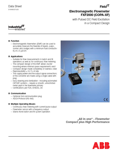
Data SheetD184S037U02FieldElectromagnetic FlowmeterFXF2000 (COPA-XF)with Pulsed DC Field Excitationin a Compact DesignIT ■Function–Electromagnetic flowmeters [EMF] can be used to accurately measure the flowrate of liquids, pulps, slurries and sludges with a minimum fluid conductiv-ity of ≥ 5 µS/cm ■Applications–Suitable for flow measurements in batch and fill operations as well as for continuous flow metering –The compact design of the EMF allows cluster mounting where minimal space requirements exist –Compact design made completely of stainless steel –Reproducibility ± 0.2 % of rate–The supply power and the output signal connections of the converter are made using a single cable with plug–Easy cleaning and sterilization – including automated CIP/SIP-systems – require a smooth, unrestricted meter pipe in the flowmeter primary –Certifications per FDA, EHEDG, 3A ■Communication–Optional 2nd communication plug –ASCII-Protocol (RS 485)■Multiple Operating Modes–Continuous flow metering with current/pulse output –Flowmeter sensor with a frequency output –Stand-Alone batch and fill system operation…All in one“ - FlowmeterCompact plus High PerformanceOverview of the Flowmeter Primary and Converter Designs Overview, Process Connections2Accuracy, Reference Conditions and Operating PrincipleDesignThe Electromagnetic Flowmeters in the Compact Design occupy a spe-cial niche. In this design, the converter is mounted directly on the flow-meter primary. This appreciably decreases installation costs because a signal cable is no longer required between the flowmeter primary and the converter.Operating PrincipleThe operation of the electromagnetic flowmeter is based on Faraday’s Laws of Induction. A voltage is generated in a conductor as it moves through a magnetic field.This measurement principle is applied to a conductive fluid which flows in a pipe through which a magnetic field is generated perpendicular to the flow direction (see Schematic Fig. 1: ).The signal voltage which is induced in the fluid is measured at two elec-trodes located diametrically opposite to each other. This signal voltage U E is proportional to the magnetic induction B, the electrode spacing D and the average fluid velocity v.Noting that the magnetic induction B and the electrode spacing D are constant values, indicates that a proportionality exists between the signal voltage U E and the average flow velocity v. The equation for calculating the volumetric flowrate shows that the signal voltage U E is linear and proportional to the volumetric flowrate.Reference Conditions per EN 29104FluidWater, conductivity 200 µS/cm ± 10 %Fluid Temperature20 °C ± 2 KAmbient Temperature20 °C ± 2 KSupply PowerNominal voltage U N ±1 %Installation Requirements, Straight Pipe Sections Upstream >10xDDownstream >5xDD = Flowmeter primary sizeWarm Up Time≥ 30 MinutesEffect on Analog OutputSame as pulse output plus ± 0.1 % of rateReproducibility – Fill OperationsThe constant boundary conditions which exist for these applications allow replacing the above instrument/system accuracy (± 0.5 % of rate) Fig. 2: , with fill operation accuracies of:± 0.2 % for T Filll≥ 4 s± 0.4 % for 2 s ≤ T Filll≤ 4 s(standard accuracy)Reproducibility – Continuous Flow Metering± 0.2 % of rate3Converter Specifications/Operating Modes 50XF4000Supply Power24 V DCContact Outputs - Optocoupler (see specific Variant)–Pulse/frequency output–Alarm contact–Forward/reverse direction signal–Synchronized output–End contactAnalog Output–Current outputContact Inputs - Optocoupler (see specific Variant)–Ext. zero return–System zero–Synchronized input–Start/stop inputData Link/ Protocol–RS 485 / ASCII–RS 485 / ASCII 2wDetector Empty PipeOperating Modes–Standard continuous.–Conti1kHz–Conti2kHz–Conti5kHz–Standard batch–Batch 1 kHz–Batch 2 kHz–Batch 5 kHz–Fill 5 kHzPlug ConnectionsConfigure Using–Operator Unit 55BE1000–Handheld Terminal 55HT4000Approvals / Certifications–3A-Certificate–FDA–EHEDG-Certificate Operating Modes, FXF2000 (COPA-XF)In addition to continuous flow metering with current and pulse outputs, the following operating modes are available.Flow Sensor for a Higher Level Fill Control Systemas a Stand-Alone “Filler” with integrated Fill-Software4Meter Size Table, Flow Ranges,Flowrate NomographMeter Size, Pressure Rating (Weld Stubs)and Flow Ranges1)Values for other process connections see Page 2Effective Flow Velocity, Variable Process Connections, PFA Flowrate NomographThe volume flowrate is a function of both the flow velocity and the flow-meter size. The Flowrate Nomograph, Fig. 5 shows the flow range appli-cable to each flowmeter size as well as the flowmeter sizes suitable for a specific flowrate.Example:Flowrate = 120 l/min (maximum value = flow range end value). SuitableMeter size DN InchStd.Press. RatingPN1)min.Flow RangeFlow Velocity0 to 0.5 m/smin.Flow RangeFlow Velocity0 to 10 m/s3 4 61/105/321/44040400 to0.2l/min0 to0.4l/min0 to1l/min0 to4l/min0 to8l/min0 to20l/min8 10 155/163/81/24040400 to 1.5l/min0 to 2.25l/min0 to5l/min0 to30l/min0 to45l/min0 to100l/min20 25 323/411¼4040400 to7.5l/min0 to10l/min0 to20l/min0 to150l/min0 to200l/min0 to400l/min40 50 651½22½4016100 to30l/min0 to3m3/h0 to6m3/h0 to600l/min0 to60m3/h0 to120m3/h80 1003416100 to9m3/h0 to12m3/h0 to180m3/h0 to240m3/hMeter SizeDN InchCal-Fac [l/min]d eff [mm]Q d eff [l/min]V eff [m/s]31/1043 4.29.445/32847.510.661/4 20 6 17.011.885/16 30 8 30.2 9.9103/8 4510 47.1 9.5151/2 10013 79.612.6203/4 15018 152.7 9.8251 20024 271.4 7.4321¼ 40030 424.1 9.4401½ 60036 610.7 9.85021000471041.0 9.6652½2000621811.411.08033000742580.511.610044000964342.9 9.25Installation Requirements,Flowmeter Primary DF23In-/Outlet Straight SectionsThe measurement principle is independent of the velocity profile as long as standing eddies do no extend into the measurement zone, e.g., after double elbows, tangential inflow or partially opened gate valves upstream of the flowmeter primary. In such situations measures should be em-ployed to normalize the flow profile.Straight sections with the same diameter as the flowmeter primary should be installed upstream and downstream. The straight length up-stream of the flowmeter primary should be of at least 10 times the diam-eter of the flowmeter primary and downstream at least 5 times. Experience has indicated that in most of the installations a straight inlet section of 3xD and a straight outlet section of 2xD is sufficient.Installation of the Flowmeter PrimaryThe flow direction should be considered during installation (fluid flows into the plug connection socket), because the flowmeter should be operated in the forward direction if possible. The flow direction for the measure-ments can be reversed using the software, if required. Generally, the con-nection plug socket should point downward for vertical installations. The flowmeter must be installed so that the meter pipe is always completely filled with fluid. Valves or other shut off devices should be installed down-stream to prevent the flowmeter primary from draining.GroundingGrounding the electromagnetic flowmeter primary is not only essential for safety reasons but also to assure proper operation. The ground screw on the flowmeter primary, for measurement reasons, is to be connected to earth. An additional ground to the connection plug is not required.For plastic or lined (with electrically insulating liners) pipelines the ground is made using a grounding plate or grounding electrode. If stray currents are present in the pipeline, it is recommended that grounding plates be installed up- and downstream of the flowmeter primary.Connection CablesAttentionThe flowmeter primary should not be installed near equipmentwith strong electromagnetic fields. A shielded interconnectioncable is recommended. It is beneficial to route the cables in met-al conduit, in which a number of cables of the same type can beinstalled together in a single conduit.Extra cable should not be coiled.Appropriate noise reduction measures should be employed, e.g., protec-tion diodes, varistors or R-C combinations (VDE 0580) for valves or con-trol switches located in the vicinity of the flowmeter system.InformationThe instrument conforms to the requirements in the EMC-Direc-tive and the NAMUR-Recommendations NE 21 3/93 “Electro-magnetic Compatibility of Equipment in Processes and Labora-tories”.InformationWhen installing the cable to the flowmeter primary, a water trapshould be provided.Output SignalsThe flowrate proportional frequency / scaled pulse output can be con-nected to an electronic counter, a SPC, a PC or a process control sys-tem. Therefore it is possible to integrate the flowmeter primary in a batch or fill system as well as utilize it in continuous flow processes.The pulse output in batch and fill operations must be processed by other peripheral instruments. This includes the control of the system, integrat-ing the flow, actuating the valves when the batch quantity is reached, cal-culating the second stage flow and monitoring the over- or under fills. A low flow cutoff feature can be turned on if required. Optionally, the inte-grated batch software can be used for single stage fill operations. Additionally, in the operating modes “Conti”, a 0/4–20 mA current output is available.Electrode AxisFor horizontal installations assure that neither of the two electrodes are located at the highest point. Any gas bubbles present in the fluid could accumulate and interrupt the electrical connection between the electrode and the fluid. The ideal installation for an EMF is assured in vertical pipe-67Installations in Larger Size PipelinesThe flowmeter primary can readily be installed in larger pipeline sizes by utilizing reducers (e.g. flanged reducers DIN 28545). The pressure drop which results from the reduction can be determined from the Nomograph Fig. 7: The pressure drop is determined in the following manner:1.Calculate the diameter ratio d/D.2.Calculate the flow velocity as a function of the flowmeter sizeand the flowrate :v =The flow velocity can also be determined from the Flowrate Nomograph Fig. 5: 3.In Fig. 7: the “Pressure Drop” can be read on the Y-axis at theintersection of the flow velocity value and the “Diameter Ratio” (X-axis) value.Specifications, Flowmeter Primary DF23Min. Allowable Absolute Pressure as a Function of the Fluid TemperatureMax. Allowable Fluid Temperature and PressureMax. Allowable Cleaning Temperature PFA-DesignIf the ambient temperature >25 °C, the difference is to be subtracted from the max. cleaning temperature.T max - °C, where °C = (T amb. -25 °C).Max. Allowable Shock TemperatureAmbient RequirementsAmbient Temperature -20 °C to +60 °CFluid Temperature-25 °C to +130 °C, CIP-cleanable, see Temperature Diagram and max. allowable cleaning temperature.Maximum allowable ambient temperature as a function of the fluid temperature for stainless steel process connections and Wafer De-Q (instantaneous flowrate)PrimaryConstant-----------------------------------------------------------LinerMeter SizeDNInchP Operate mbar absat T Operate °C PFA3 – 100 1/10 – 4≤130Process connections Liner PFAMeter SizeDNInchP Operate bar at T Operate °C Wafer Design,Weld stubs DIN 11850Weld stubs DIN 24633- 1001/10- 410–40≤130Weld stubs ISO 203725-1001- 410–40≤130Food Ind. fittings DIN 118513- 401/10-1½ 50-1002- 44025≤≤130130Tri-Clamp DIN 326763- 1001/10- 410–16≤130Fixed-Clamp 10- 403/8-1½10≤130External threads ISO 228 / DIN 29993- 251/10- 110≤130CIP-CleaningLiner T max °C T max minutes T amb °C Steam cleaning orLiquid cleaningPFA15014060602525Liner Temp.-Shock Max. Temp.-Diff. °CTemp.-Gradient°C/minPFAanyany∆∆8Storage Temperature -25 °C to +70 °CVariant Overview Series 2000 (Stainless Steel Design) Material Load Curves for Wafer Design Instrument Model DF23Materials, Flowmeter PrimaryProcess Connection MaterialGasket Materials, Electrical Connections, Weight and DesignSupply Power From converterWeightSee Dimensions Pages 9 – 13DesignFlowmeter primary with integrated µP-converterFlowmeter primary and converter housing in stn. stl. 1.4301 [304]Process Connections DN 3 – 100 [1/10” – 4”]See Page 2 and Pages 9 – 13Protection ClassStandard IP 67, option tropicalized Max. Pipeline Vibration15 m/s 2 (1.5 g) for f = 10 – 150 HzMax. Allowable Fluid Temperature and Pressure Process Connections DF23*)Higher temperatures for CIP/SIP cleaning are allowed for restricted time periods, see Table …Max. allow. Cleaning Temperature“Model:DF23B E T R Q P S F WM e t e r S i z eP r o c e s s C o n n ’s1/8“-S a n i t a r y c o n n ’sE x t e r n a l t h r e a d sT r i -C l a m p D I N 32676W e l d s t u b s D I N 11850W e l d s t u b s D I N 2463W e l d s t u b s I S O 2037F o o d I n d . f i t t i n g D I N 11851F l a n g e sW a f e r D e s i g n11/25x PED[DGRL]21/12xS E P S e c t . 3,P a r . 331/10x x x x x x x 45/32x x x x x x x 61/4x x x x x x x 85/16x x x x x x x 103/8x x x x x x x 151/2x x x x x x x 203/4x x x x x x x 251xx x x x x x x 321-1/4x x x x x x x C o n f o r m i t y p e r C a t e g o r y I I I M o d u l e B 1+D ,F l u i d G r o u p 1401-1/2x x x x x x x 502x x x x x x x 652-1/2x x x x x x x 803x x x x x x x 1004xxxxxxxLiner Material Electrode Material Electrode Design Standard OthersStandardOthers PFAHast.-C4(1.4539 for weld stubs, Food Ind. fittings & Tri-Clamp)SS 1.4539SS1.4571[316Ti] Tantalum, TitaniumFlat head Pointed head (≥ DN10 [3/8”])StandardOptionWafer Design NoneWeld stubs SS 1.4404 [316L]SS 1.4435 [316L]Food Ind. fittingDIN 11851SS 1.4404 [316L]SS 1.4435 [316L]Tri-Clamp DIN 32676SS 1.4404 [316L]SS 1.4435 [316L]Fixed-Clamp SS 1.4404 [316L]SS 1.4435 [316L]External threadsSS 1.4404 [316L]SS 1.4435 [316L]Process Connection Materials Gasket Materials Wafer Design noneWeld stubs Food Ind. fitting Tri-Clamp Fixed-Clamp External threads EPDM (Ethylene-Propylene) std. with FDA-ApprovalSilicone with FDA-Approval (option)Flat housing gasketSiliconeProcess Connections Liner PFA Meter Size DN Inch PSbar at TS °C Wafer Design 3–501/10-2 65–1002½-44016≤≤130*)130*)Weld stubs 3–401/10-1½50, 802, 365, 1002½, 4401610≤≤≤130*)130*)130*)Tri-Clamp3–501/10-265–1002½-41610≤≤121121Food Ind. fittings 3–401/10-1½50, 802, 365, 1002½, 4401610≤≤≤130*)130*)130*)External threads 3–251/10-110≤130*)Fixed-Clamp 10–403/8-1½10≤130*)DN Inch910Specifications, ConverterFlow RangeSelectable between 0.05 – 1* Cal-FacReproducibility0.2 % for T Fill≥ 4 s0.4 % for 2 s ≤ T Fill≤ 4 sFlow DirectionForward/reverseMinimum Conductivity≥ 5 µS/cm, ≥ 20 µS/cm DN 3 - 8 [1/10” - 3/16”],≥ 20 µS/cm deionized waterElectrical Connections8-pin plug (supply power, signals)4-pin plug (data link RS485 - option)Supply Power24 V DC, allowable voltage deviations +/-30 %Ripple ≤ 5 %PowerDN 3 to DN 100 [1/10” to 4”] ≤ 6 W (flowmeter primary incl. converter) Magnetic Field Excitation12.5 Hz / 25 HzAmbient Temperature-20 °C to +60 °C (see also Temperature Diagram Fig. 8: ) Response Time for Pulse-/Frequency OutputsMin. response time T0/99 =Min. fill time T Fill = 2 sLow Flow CutoffSelectable from 0 to 10 % of max.Output Signals–Scaled pulse output,passive, optocoupler0 ≤ U CEL≤ 2 V; 16 V ≤ U CEH≤ 30 V2 mA ≤ I CEL≤ 220 mA; 0.2 mA ≤ I CEH≤ 2 mASetting range: 0.001 – 1000 pulses per selected unitPulse width: 100s – 2000 msfmax : 5 kHzPIN 3 and 4–Flowrate proportional frequency output1.2 or 5 kHz for flowrate = 100 %passive, optocoupler0 ≤ U CEL≤ 2 V; 16 V ≤ U CEH≤ 30 V2 mA ≤ I CEL≤ 220 mA; 0.2 mA ≤ I CEH≤ 2 mAPIN 3 and 4–Current output (selectable)Load ≤ 600 for 0/4–20 mA, 0–10– 20 mA, 4–12–20 mALoad ≤ 1200 for 0/2–10 mALoad ≤ 2400 for 0–5 mAPIN 5 and 8–Data link RS 485Max. cable length 1200 mMax. no. of instruments: 32 Instruments in parallelMax. baudrate: 9600 BaudCommunication-Protocol: ASCII 2W“Communication plug” PIN 3 and 4Connection to Handheld-Terminal or SPC, PCS, PC –Handheld Terminal 55HT4000Plug into “Communication Plug Socket”Supply power 24 V DC over PIN 1 and 2–Contact output (function of operating mode) Alarm, forward/reverse, synchronized or end contact passive, optocoupler0 ≤ U CEL≤ 2 V; 16 V ≤ U CEH≤ 30 V0 mA ≤ I CEH≤ 0.2 mA, 2 mA ≤ I CEL≤ 220 mAPIN 1 and 3–Contact input (function of operating mode) Ext. zero return, system zero, synchronized input,Start/stop inputOptocoupler16 V ≤ U ≤ 30 V, R i = 2 kOhmPIN 5 and 21MagneticFieldExcitation---------------------------------------------------------------µΩΩΩOverview, Possible Converter VariantsLegends: x Default setting o Selectable A, B, K Only selectable for specific operating mode. Design Level BVariant0207Hardware Contact output x x Contact input x x Pulse passive x x Current output xRS 485xMenusOperating mode Standard conti.K x x Standard Batch B o o Batch 1 kHz B1o o Batch 2 kHz B2o o Batch 5 kHz B5o o Filler 5 kHz A o o Conti 1 kHz K1o o Conti 2 kHz K2o o Conti 5 kHz K5o o Contact output Alarm x x Fwd./Rev.o o Synchronized o o End contact A A Contact input Ext. zero return x x System zero o o StartAA Current outputK K1K2K5Data link ASCII x ASCII2w o DEP K KPlug TypePIN-Assignments for the Standard Plug FXF2000Assignments Communication Plug Variant PIN 1PIN 2PIN 3PIN 4PIN 5PIN 6PIN 7PIN 8PIN 1PIN 2PIN 3PIN 42P7G2Ux V8X1U+U-../..+ 25 V B A 7P7X1Ux V8+U+U-–../..../..../..../..Customer Specific Variant 20P7../..Ux V8+U+U-–+ 25 V B A 21P7G2Ux V8X1U+U-../..../..../..../..../..22P7Vc Ux V8+U+U-–../..../..../..../..23P7G2Ux V8X1U+U-Air../..../..../..../..⊥⊥Interconnection Diagram FXF2000, High-Side Switching, Model DF23, Design Level BDesign High-Side Switching(Pulse output, current output, contact input, contact output, supply power, data link, supply power, handheld terminal) a)Scaled pulse output, passive optocoupler, pulse width selectable from 0.100 ms to 2000 ms fmax 5 kHz as a function of the selection in the submenu “Operating mode”, 0 V ≤ U CEL ≤ 2 V, 16 V ≤ U CEH ≤ 30 V2 mA ≤ I CEL ≤ 220 mA; 0.2 mA ≤ I CEH ≤ 2 mAConnection plug assignments PIN 3, 4; Function Ux, V8d)Current output (selectable)Load ≤ 600 for 0/4–20 mA, 0–10– 20 mA, 4–12–20 mA Load ≤ 1200 for 0/2–10 mA; load ≤ 2400 for 0–5 mA Connection plug assignments PIN 5 and 8; Function +, –e)Contact output, function selectable dependent upon the selection in the submenu “Operating mode”, Synchronized signal (output signal synchronized to the excitation), F/R signal or end contact,passive optocoupler, 0 V ≤ U CEL 2 V, 16 V ≤ U CEH ≤ 30 V / 0 mA ≤ I CEH ≤ 0.2 mA, 2 mA ≤ I CEL ≤ 220 mA Connection plug assignments PIN 1, 3; Function P7, Uxf)Contact input, function selectable dependent upon the selection in the submenu “Operating mode”, Start/Stop, external totalizer reset, system zero 1), no function, passive optocoupler, 16 V ≤ U ≤ 30 V, Ri = 2 kOhm Connection plug assignments PIN 2, 5; Function G2, X1g)Supply power 24 V DC ± 30 %, ripple ≤ 5 %Connection plug assignments PIN 6, 7; Function U+, U-i)Data link RS 485, 2-Wire, V PP = 5 V, input resistance ≥ 12 kOhmmax. cable length ≤ 1200 m, shielded cable with twisted pairs required, Baudrate 110 - 9600 Baud, max. 32 instruments in parallel,Communication plug assignments PIN 3, 4; Function B, A (RS 485)j)Connection for Handheld Terminal 55HT4000Communication plug assignments PIN 3, 4; Function B, A (RS 485);Communication plug assignments PIN 1, 2; Function , +25 V (supply power for 55HT4000)1)Initiates a system zero adjustment procedure.The fluid must be at absolute zero flowrate and the meter pipe must be completely ment:To maintain the EMC-Requirements the instrument must be connected to earth. When the housing is opened the EMC-Protection is voided.Assignment Connection Plug Communication {Plug PIN-No.123456781234Legends Functions (PIN-Assignments)Functions (PIN-Assignments)a)Ux V8d)+–e)P7Ux f)G2X1g)U+U-i)B A j)+25V B A ⊥ΩΩΩ⊥Fig. 15:Interconnection Diagram, High-Side Switching, In-/Outputs with PIN-Assignments for the Connection and Communication PlugsInterconnection Examples for Peripherals FXF2000 (COPA-XF), Model DF23, High-Side Switching, In-/Outputs/Data LinkVariant Overview High-Side Switching and SPC-ConformityVariant: 2, 21, 23High-side switching SPC conf.Variant: 20 High-side switching SPC conf.Variant: 7High-side switchingPulse outputInputContact output X1 (5)G2 (2)UX (3)P7 (1)V8 (4)V8 (4)– (8)+ (5)P7 (1)UX (3)X1 (2)InputPulse outputContact output Current outputactivePulse outputContact outputV8 (4)P7 (1)Vc (2)UX (3)2nd Pulse outputCurrent output– (8)+ (5)active – (8)+ (5)V8 (4)UX (3)P7 (1)Pulse outputContact outputCurrent output activeVariant: 22High-side switching SPC conf.Fig. 17:Variant Overview High-Side Switching and SPC-ConformityInterconnection Diagram FXF2000, High-Side Switching/Plug with Installed Cable, Model DF23,Ordering Information: Electromagnetic Flowmeter Model DF23In addition to the Ordering Number, please include the following information: Fluid, fluid temperature, operating pressure, pipeline design (grounding plates) 1)Installation accessories see Table H in the Price List 2)Grounding electrodes from DN 3 [1/10”]Compact Design FXF2000 (COPA-XF)DF23Process ConnectionsWafer Design 1)Weld stubs DIN 11850(standard)Weld stubs DIN 2463Weld stubs ISO 2037 (DN 25-100 [1” - 4”]) Food Ind. fitting DIN 11851Tri-Clamp DIN 32676Fixed-Clamp (DN 10-40 [3/8”-1½”]) External threads ISO 228/DIN 2999(DN 3-25 [1/10” - 1”]) Without adapter (no coupling nut or screws)W R Q PS T C EV Liner Material PFA P Meter SizeDN 31/10”DN 45/32”DN 61/4”DN 85/16”DN 103/8”DN 151/2”DN 203/4”DN 251”DN 321¼”DN 401½DN 502”DN 652½”DN 803”DN 1004”030406081015202532405065801H Signal ElectrodeMaterial / Ground Electrode Material 2)Stn. stl. (1.4539)/ none (standard)Stn. stl. (1.4571[316Ti])/ noneHastelloy C-4 (2.4610)/ noneTitanium / noneTantalum / noneF S H M T Stn. stl. (1.4539)/ with (standard)Stn. stl. (1.4571[316Ti])/ withHastelloy C-4 (2.4610)/ withTitanium / withTantalum / withR E O I Q Pressure Rating PN 10Tri-Clamp (DN 65-100 [2½”- 4”]), External threads/Food Ind. fitting/Weld stubs (DN 65, 100 [2½”, 4”])PN 16Wafer Design/Tri-Clamp (DN 3-50 [1/10”-2”]), Food Ind. fitting/Weld stubs (DN 50, 80 [2”,3”])PN 40Wafer Design (DN 3-50 [1/10”-2”]), Food Ind. fitting/Weld stubs (DN 3-40 [1/10”-1½”])C D F JIS K10Wafer Design DN 3-100 [1/10” - 4”] ANSI CL 150Wafer Design DN 3-100 [1/10” - 4”] ANSI CL 300Wafer Design DN 3-50 [1/10” - 2”]K P QProcess Connection Materials None (only Wafer Design) Stn. stl. 1.4404[316L)(standard)04Accessories None (standard) With instrument mounting element A CTemperature Range Standard design <130 °C SCertifications None (standard)Material Traceability Certificate 3.1B per EN 10204 and Pressure Test per AD-2000 Inspection Report per EN 10204 3.1B Pressure Test per AD-2000A D F G3) Variant No. ≥ 20: customer specific Variant4) For use in applications with high grease contentAttentionTo configure the converter the Operator Unit 55BE1000 is required and the housing cover must be removed.ATTENTION! When the housing cover is removed the EMC-Protection is limited.If a data link option is included in the converter, the converter can be configured without removing the cover from a Handheld Terminal 55HT4000, PCS-System or PC using the ASCII-Protocol.Compact Dsg. FXF2000 (COPA-XF) DF23Protection Class IP 67 Standard) Tropicalized 24Supply Power 24 V DC H External Connections Connection plug (angled),(standard) (for Variant selection 07) Connection plug (angled),plus communication socket and plug (for Variant selection 02)16In-/Outputs (Variant) 3)(see External Connections)Contact output /pulse passive, opto /contact input/RS 485 (2nd plug) (6) Contact output /pulse passive, opto /contact input/current output (standard) (1)0207Application StandardFactory Plate German EnglishG EDesign Level BGasket MaterialsEPDM with FDA-Approval (standard) Silicone with FDA-Approval (option) None (only Wafer Design)E S OElectrode Design StandardPointed head 4)(from DN 10 [3/8”])12Ordering Information Operator Unit 55BE1000 Ordering Number55BE1DesignWith 9 V battery for lighting the display10A Factory PlateGerman English 1 22122Ordering Information Handheld Terminal 55HT4000Ordering Number55HT4Keypad LayoutStandard1Supply Power 24 V AC/DC1Connection Cable with Plug2.5 m with straight plug, Handheld Terminal10 m with angle plug, for panel mounting12Design Level0Factory PlateGermanEnglish 12Fig. 20:Handheld Terminal 55HT4000 for Data Entry.A prerequisite is a FXF2000 design which includesa data link RS 485 and a communication plug socketD 184S 037U 02 R e v . 02The Industrial IT wordmark and all mentioned product names in the form XXXXXX IT are registered or pending trademarks of ABB.ABB has Sales & Customer Support expertise in over 100 countries worldwide.The Company’s policy is one of continuous product improvement and the right is reserved to modify the information contained herein without notice.Printed in the Fed. Rep. of Germany (03.04)© ABB 2004ABB Ltd.Oldends Lane, Stonehouse Gloucestershire, GL 10 3TA UK Phone:+44(0)1453 826661Fax:+44(0)1453 829671ABB Inc.125 E. County Line Road Warminster, PA 18974USA Phone:+1 215 674 6000Fax:+1 215 674 7183ABB Automation Products GmbH Dransfelder Str. 237079 GöttingenGERMANYPhone:+49 551 905-534Fax:+49 551 905-555CCC-support.deapr@。
ABB-电磁流量计

DN 3-300:Ex d e ia ma IIC T6… T2
CL I ZN2 Ex nA nC IIC T4 … T3
>DN 300:Ex d e ia IIC T6… T2
DIP:CL II,III / DIV1 / GP EFG / T70 OC … Tmedium DIP:CL II / DIV 1 / GP EFG
DN 3-300:Ex d e ia ma IIC T6… T2 >DN 300:Ex d e ia IIC T6… T2 DIP:CL II / DIV 1 / GP EFG
ൟো
FEP311ǃFEP315
⌟䞣ؐ䇃Ꮒ
ᷛ⌟˖ޚ䞣ؐⱘ 0.4 % 䗝乍˖⌟䞣ؐⱘ 0.2%
ᷛ鹵ሎᇌ㣗ೈ
DN 3 ... 2000 (1/10 “ ... 80 ")
FEPF3E2⟚P1(3ࡳ2无1㛑˄防˅᮴爆䰆功能)
ൟোὖ分䗄体˄型ߚԧൟ˅ 流⌕量䞣计䅵传Ӵ感ᛳ఼器
FFEEPP332255(˄防䰆爆⟚区ऎZo=nReQ2H/DiZH
FFEEPP33252(5˄防䰆爆⟚区ऎZon=eRQ1H/Div'.1L)Y˅
IEC
IEC
Ex nA IIC T6 … T3
DN 3-300:Ex e ia ma IIC T6… T2 Gb
>DN 300:Ex e ia IIC T6… T2 Gb
Ex tD A21 IP6X T85 OC … Tmedium
Ex tD A21 IP6X T85 OC … Tmedium
FM
ൟোὖ䗄˄䆒䅵䞛⫼䖰FবM䗕఼˅
⬉⌕䕧ߎ
4 ... 20 mAˈ᳝⑤᮴⑤
㛝ކ䕧ߎ
ৃՓ⫼䕃ӊᴀഄ䜡㕂Ў᳝⑤᮴⑤
ABB质量流量计FCM2000的数据采集
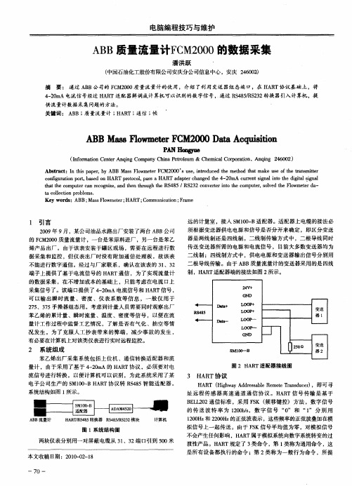
A B质量流量计F M20 B C 0 0的数据采集
潘洪跃
( 中国石油化工股份有限公 司安庆分公 司信息中心 ,安庆 2 60 ) 4 0 Z
摘 要 : 通过 A B公 司的 F M20 B C 0 0质量流量计 的使 用 ,介绍 了利 用变送 器组 态端 口,在 H R A T协议基础 上 ,将
制,H R A T适配器端的接法如图 2 所示 。
端子上提 供了基于电流信号 的 H R 通信 ,为了实现 流量计 AT
的数据采集 ,在不增加成本 的基础 上 ,只能考 虑在 电流 口上
采集信号了。该端 口 提供 了 4 2m -0 A电流信 号和 H R 信号 , AT 可 以输 出瞬 时流量 、密 度 、仪表 系数 等信 息 ,一 般 仅用 于
3 H T协 议 AR
HA T ( ih a d rsal R mo r sue) R H gw yA desb e t Ta d cr ,即可寻 e e n
址 远 程传 感 器 高速 通道 通 信协 议 。H R A T信号 传输 是 基 于
B L 22通信标准 ,采用 F K ( E L0 S 频移键控) 方法 , 字信 号 数 的传 送 波 特 率 为 10b ,数 字 信 号 “ ” 和 “ ”分 别 用 20/ s 0 1
A B流量计 B H R / S 8 转换器 R 4 5 S 3 模块 A TR 4 5 S8/ 22 R 计算机
Ab t a t n t i p p r b B Ma s F o s r c :I h s a e , y AB s lwme e C 0 0’ s , n r d c d t e me o h tma e u e o e t n mi e t rF M2 0 S u e i t u e h t d t a k s ft r s t r o h h a t
ABB流量仪表概述--full version

ABB质量流量计样本
ABB质量流量计样本ABB是全球领先的工业技术公司,其质量流量计是一种用于测量液体或气体流量的仪器。
ABB质量流量计样本出色的设计和可靠性使其在工业自动化和流程控制领域得到广泛应用。
该样本将重点介绍ABB的质量流量计的特点和应用。
ABB的质量流量计采用了热式传感器技术,使用了革命性的质量测量原理。
其对流体中的物质进行连续热定点追踪,从而实现了高精度的质量流量测量。
同时,ABB质量流量计具有快速响应、宽测量范围和高可靠性等优点,非常适用于各种工业流程的质量流量控制。
ABB的质量流量计样本中包括多种型号和规格的流量计,以满足不同需求。
其中,一种常见的型号是ABB的CoriolisMaster。
这种质量流量计采用两根弯曲的管道,通过测量流体在管道中沿两个方向的振动来计算质量流量。
CoriolisMaster具有极高的精确度和稳定性,能够在各种工况下提供准确的测量结果。
另一种常见的ABB质量流量计是ThermalMaster。
这种流量计使用了Thermal Gas Mass Flow技术,通过测量热量传导来计算质量流量。
ThermalMaster适用于气体流量测量,能够测量极低至微米水平的流量,且不受压力、温度和湿度等环境因素的干扰。
除了CoriolisMaster和ThermalMaster之外,ABB还提供其他型号的质量流量计,如VortexMaster、MFM300和MassMaster等。
每个型号都具有特定的优点和适用范围,以满足不同行业、过程和应用领域的需求。
例如,VortexMaster是一种基于涡街原理的质量流量计,适用于液体和气体的测量。
它具有无移动部件、准确可靠和耐久性强等特点。
MFM300是一种用于纳米流量测量的质量流量计,适用于实验室和研究领域的应用。
它能够测量液体和气体的微小流量变化,提供高精度和稳定性。
MassMaster是一种用于大流量测量的质量流量计,适用于石油、化工和电力等行业的应用。
ABB测量产品综合样本

Unrivalled in its scope and application expertise, ABB 产In效st率ru、m节en约ta能t源io及n 实pr现ov工id厂e安s 全so提lu供ti解on决s方fo案r。m长a期xi以m来izi,ng在全pr球od范u围ct内iv,ityA,BB 在en经e过rg验y 证ef的fic测ie量n原cy理, 的an基d础p上la进nt行s持af续et创y.新A,B拥B有’s超w过or一ld个w世id纪e的p经re验se积n累ce,, 成 a history of innovation based on proven measuring principles, 为an满d足o您ve仪r器a仪c表en需tu求ry的o最f佳ex选p择e。rience, means that ABB is the best choice for your instrumentation needs.
ABB仪器仪表以其专业领袖者的水平设计、制造及提供了一宽泛序列的测量、分析
ABB is recognized globally for expertise in designing, manu和fa控ct制ur解in决g 方an案d,s在u全pp球ly范in围g内a得w到id普e遍ra认n可ge。其of提h供ig的h 解qu决a方lit案y,能a够cc实u现ra高te水平 且an精d确re可li靠ab的le测m量e,a并su符re合m各e个n国t, 际an标a准ly的tic认a证l a。nAdBcBo仪n器tr仪ol表s旗olu下t的io全ns球t制ha造t 工 are certified to international standards. These are all supported 厂by、a校c准o实m验pr室e及he服n务siv中e心w形o成rld了w一id个e完n整e的tw国o际rk化o网f m络,an众u多fa的ct专ur业in工g程p师la,nt为s, 您ca提lib供ra满ti足on您l的ab需o求ra的to应ri用es支a持n及d 服se务rv。ic据e此ce,nAtBerBs远w不h止er是e一hu家n仪d器re仪ds表供应 of engineers provide the application support and service you 商ne,e它d.是T协he助您re的su企lt业is成t长ha、t 提A高BB您企is业fa竞r 争m力or的e重th要a伙n 伴an。instrumentation supplier. ABB is a partner to help your business grow and be more competitive.
ABB涡街流量计HART475菜单VT40

INIT DBASE(格式化数据)
5 Points(5点平均值)
MDBASE>BDBASE(主板到底板)
del.data>Enter(确认转移数据?)
KIT-FRAM>DBASE(打包存储到显示面板)
DBASE>KIT-FRAM(显示面板到打包存储)
INIT FLASH(初始化闪屏)
QV
QV+CMP
Low Dis Frequen(震动频率低值)
High Dis Frequen(震动频率高值)
Low Dis Gain(增益值低值)
High Dis Gain(增益值高值)
Temp Par(温度参数)
Temp Correct(修改温度)
Temp-Interval
Service Display(服务级显示菜单)
Freq Values(频率值)
BP Range(频率范围)
BP State(测量状态)
Input Values(流量输入值)
Vib In Values(振动值)
Input Quality(处理后流量输入值)
Gain Values(增益值)
totali value(累积量)
over flow(溢出流量)超过累积量以外的流量
unit totali(累计单位)
totali resrt (累计清零)
damping 阻尼时间
hard ware config 硬件配置
I/HART 电流输入和HART连接
puls -bin(脉冲输出)
Q-alarm (流量报警)
on/off打开/关闭
Puls output(脉冲输出)
ABB 电磁流量计
安全要点介绍:使用调节电磁流量计系统(EMF)是按照设计技术制造操作安全的。
流量计根据规范专门安装使用。
每一个超过规范的使用被视为违规。
因此制造商不承担任何危险的结果。
使用者自责如此使用的危险结果。
使用的说明包括安装、起动和随后制造商特殊要求的服务。
安装、起动和操作人员在试图安装、启动和服务之前请阅读本使用说明和安全要点。
只有合格的人员才能接近该仪表。
该人员必须熟悉在说明公告内包含的警告和操作要求。
遵守在本文件中通过符号标明的警告要点:危险材料信息如果进行维修时。
了解1986/08/27的废料排放法(A bfG.11, 特殊废料)。
特殊废料的业主是有责任注意和根据1986/11/01的危险材料法(GefStoffV,17,通过保护责任)老板也有责任保护其员工。
我们必须提及:a)全部仪表本体和/或仪表转换器要返回ABB自动化公司进行维修是可完全避免任何危险的材料(酸、碱、溶剂等);b)仪表本体必须平直因此危险的材料不被压制。
在仪表室和管道之间有空穴在本体上。
因此在测量危险材料后这些空穴可能被压制(见危险材料法- GefStoffV)。
两半仪表室使用螺栓固定。
对于仪表本体大于14” DN350,排液孔位于室底部。
为了避免危险的材料进入磁性线圈和电极区可以去除排压。
c)为了工作和维修,要求记录完成a)和b)的测量表。
d)任何去除危险材料的成本将有使用者承担。
内容:页1. 仪表和转换器的协调1.1 适用性1.2 协调型号1.3 使用说明1.4 规格页1.5 仪表本体设计概论1.6 功能描述2. 装配和安装2.1 检查2.2 流量计本体安装要求2.2.1 流量计本体安装2.2.1.1 保护等级 IP68 的安装2.2.2 高温设计的安装2.2.3 大尺寸管线的安装3. 流量计可替代的部件3.1 更换部件表:模块盒 10DX3121/31223.2 更换部件表:铝连接盒≤12” DN3004. 使用说明的有关安全章节4.1 接地4.1.1 在管线上应用负极腐蚀保护(CCP)的安装和接地4.1.1.1 应用负极腐蚀保护电压管线内部绝缘4.1.1.2 混合系统: CCP和接地保护的管线4.1.2 供电的连接4.1.2.1 供电和信号线的连接4.1.2.2 信号线解释4.1.3 连接图4.1.4 连接区域5. 起动5.1 流量计本体的初步检查5.2 保养6. 使用转换器的流量计本体的测试和错误查找1. 仪表和转换器的协调!您是使用一直流脉冲流量计系统。
质量流量计规格书
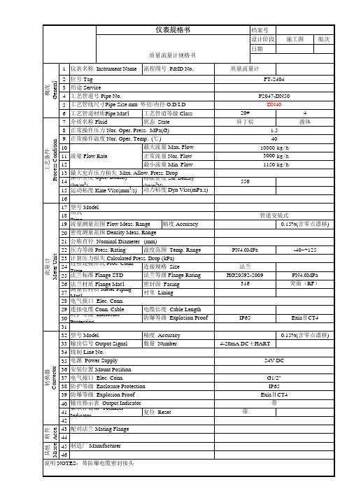
P2001-DN50
DN40 20# 丙烷异丁烷正丁烷 2.5 40 12000 kg/h 5000 kg/h 3000 kg/h 550 4 液态
14 操作密度 Oper. Density (kg/m3) 标准密度 Std. Density (kg/m3N)
15 运动粘度 Kine Visc(mm /s) 动力粘度 Dyn Visc(mPa.s) 16 17 型号 Model 18 形式 Type 精度 Accuracy 19 流量测量范围 Flow Meas. Range 密度测量范围 Density Meas. Range 20 21 公称直径 Nominal Diameter (mm) 温度范围 Temp. Range 22 压力等级 Press. Rating 23 计算压力损失 Calculated Press. Drop (kPa) 24 过程连接形式 Proc. Conn. Type 连接规格 Size 法兰等级 Flange Rating 25 法兰标准 Flange STD 密封面 Facing 26 法兰材质 Flange Mat'l 27 测量管材质 Meter Piping Mat'l 衬里 Lining 28 电气接口 Elec. Conn. 电缆长度 Cable Length 29 连接电缆 Conn. Cable 30 防护等级 Enclosure Protection 防爆等级 Explosion Proof 31 精度 Accuracy 32 型号 Model 数量 Number 33 输出信号 Output Signal 34 线制 Line No. 35 电源 Power Supply 36 安装位置 Mount Position 37 电气接口 Elec. Conn. 38 防护等级 Enclosure Protection 39 防爆等级 Explosion Proof 40 输出指示表 Output Indicator 41 累积计数器 Totalizer Indicator 复位 Reset 42 43 配对法兰 Mating Flange 44 45 制造厂 Manufacturer 46 说明 NOTES:带防爆电缆密封接头
ABB质量流量计中文说明书

ABB质量流量计中文说明书发布时间:10-04-08 来源:点击量:33792 字段选择:大中小操作手册D184B111U02科里奥利质量流量计FCM2000可同时测量质量流量、密度和温度标准软件D699G001U01 A.3x产品名称FCM2000操作手册零件号. D184B111U02发行日期: 11/04版本: 01制造商:ABB Automation Products GmbHDransfelder Str. 237079 Göttingen, Germany电话: +49 (0) 55 19 05- 0传真: +49 (0) 55 19 05- 777© Copyright 2004 by ABB Automation Products GmbH We reserve the right to technical amendments.本文档有版权保护.本文档中的信息仅用于帮助用户对设备进行安全有效的操作.没有版权所有者的书面批准不得全部或部分复制其内容.2 FCM2000 D184B111U021 基本安全信息和使用方法1 基本安全信息和使用方法1.1 基本安全信息1.1.1 仪表安全标准􀁺 本仪表符合压力设备规范以及最新技术的安全要求。
本仪表已根据安全要求通过工厂测试,并根据正确的订单发货。
为使仪表在操作过程中仍符合安全指标,必须遵守本操作手册中列出的要求。
􀁺 请注意关于防暴设计的仪表启动的特别信息,在本手册第七章。
􀁺 仪表符合EN61326/NAMUR NE21 的电磁兼容(EMC)要求及低电压指示。
􀁺 对于尺寸直到DN100(4”)的科里奥利质量流量计有防水外壳可选项,流量计传感器的最大工作压力为PS=40bar(外壳的爆炸压力为PS>60bar)。
ABB流量计操作说明
ABB流量计操作说明
1、瞬时流量计波动大?
A、信号强度波动大;
B、本身测量流体波动大;
解决方法:调整好探头位置,提高信号强度(保持在3%以上)保证信号强度稳定,如本身流体波动大,则位置不好,重新选点,确保前10D后5D的工况要求。
2、外夹式流量计信号低?
管径过大,管道结垢严重,或选择安装方式不对。
解决方法:对于管径过大、结垢严重,建议采用插入式探头,或选择“Z”型安装方式。
3、插入式探头使用一段时间后信号降低?
可能探头发生偏移或探头表面水垢厚。
解决方法:重新调整探头位置,清冼探头发射面。
4、开机无显示
检查电源属性是否与仪表的额定值相对应,保险丝是否烧断,如以上问题不荐在,对建议把仪器发回我司由专业技术人员检查。
5、开机后仪表仅有背光,无任何字符显示
此情况一般为程序芯片失,建议把仪器发回我司进行处理。
6、仪表在现场强干扰下无法使用?
供电电源波动范围较大,周围有变频器或强磁场干扰,接地线不正确。
解决方法:给仪表提供稳定的供电电源,仪表安装远离变频器
和强磁场干扰,有良好的接地线。
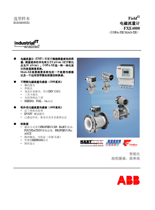
ABB流量计
3
电磁流量计 FXE4000 (COPA-XE/MAG-XE)
准确度,参考条件及操作原理
参考条件符合EN 29104
液体温度 20 °C ± 2 °C
环境温度 20 °C ± 2 °C
电源 供电电压符合铭牌UN ±1 % ,且 频率f ±1 %
安装条件 上游>10DN,直管段 下游>5DN,直管段 D=流量计传感器尺寸
选型样本
D184S044U02
■ 电磁流量计(EMF)可用于精确测量液体的流 量,测量液体的导电率大于5 µS/cm(对于软化 水为20 µS/cm)。COPA-XE是一种一体化设 计的流量测量系统。 MAG-XE流量测量系统包括一个流量传感器 以及一个远传型带微处理器的转换器。
■ 不锈钢电磁流量传感器(2000系列) - 螺纹接头 - 焊接头 - 食品行业接头,符合DIN 11851 - 三爪卡接头 - 夹持型和法兰型 - EHEDG,FML,3A认证
■ 铝外壳电磁流量传感器(4000系列) - 法兰型和夹持型 - DVGW 测试报告 - 已通过冷水、废水以及非水液体认证
■ 转换器 - 通讯方式采用PROFIBUS DP,HART-协议, FOUNDATION现场总线,PROFIBUS PA, ASCII - 脉冲输出,可组态(有源/无源) - 外置的EEPROM芯片 - 图形显示
对于测试场合,EN 29104中规定的参考条件必须得到满足。对 于已经通过认证的仪表,前、后直管段有特殊要求(参见第7 页)。
电极轴 流量计可安装在垂直,水平或者倾斜的管道上。如果可能,应 保持电极轴的水平位置。应避免出现垂直的电极轴向。理想的 安装实例如图3所示。
D 8°
d
在较大口径管道中的安装 利用缩径接头(例如法兰连接的缩径接头DIN 2616),流量 计传感器可方便的安装在较大口径的管道中。由于管径缩小而 造成的压降可在图4的曲线图中确定。压降将根据下列方法确 定:
ABB AquaMaster 电磁流量计产品指南说明书

Anytime, anywhere flow measurementABB’s AquaMaster electromagnetic flowmeter – the most versatile flowmeter availableIntroductionMeasuring potable water has been one of the biggest challenges for the water industry. The need to measure not only water flows but also leakage demands the highest levels of accuracy and availability. Added to this is the cost of installing the meters. Traditionally, installing more meters has meant having to build costly installation chambers, incurring costs in construction and in purchasing and maintaining additional ancillary equipment such as isolation valves and bypass lines.With the requirement to monitor flow as widely as possible, there is also an increased need for meters to be installed in remote locations. This brings its own challenges in terms of maintenance and data collection, as well as powering the devices where electronic meters are used.T h e ApplicationThe growing realization of the need to manage and conserve potable water supplies is leading to an expanding demand for metering in a growing range of applications. These include:– Leakage management– District metering (DMAs)– Clean water applications– Abstraction– Water distribution and network management– IrrigationThe need to ensure that large-scale users are accurately billed for the water they use has also seen a demand for equipment capable of delivering the highest levels of accuracy for use inrevenue management applications.Maximize measurement flexibility through anytime, anywhere access to flow dataMeasurement made easyAnytime, anywhere flow measurementABB’s AquaMaster electromagnetic flowmeter – the most versatile flowmeter availableThe ChallengeGiven the size of water distribution networks, it is inevitable that some losses will occur during transit. These have to be accurately accounted for in order to gain the best possible estimate of water flows. When it comes to the type of flowmeter used, the accuracy of the measurement can be affected by various factors, including age, overall condition and the flowmeter technology being employed.Deposits accumulating in the pipeline can also lead to reduced accuracy, as well as increasing the risk ofunder-reading.Where mechanical meters are used, there is also the added likelihood of deteriorating accuracy caused by wear and tear. This will affect not only the water balance but also the estimation of leakage within the distribution system.Whichever meter type is used, regular verification of accuracy will be needed to help minimize the impact of any errors, which can bring its own challenges. The need for mechanical meters to be periodically tested, recalibrated and repaired, for example, means that they have to be removed, requiring users either to replace the meter with a temporary device or cease measurement until the meter is refitted back intothe line.Ultrasonic flowmeters, which use ultrasonic sound waves to help ascertain the velocity and volume of water passing through the pipe, also suffer various drawbacks. Transit time meters in particular can struggle to handle flows with high levels of particulate matter, requiring a strainer to be fitted.Both transit time and Doppler meters can also be affected by velocity profile distortions, requiring from 10 to 40 upstream diameters, depending on the severity of the disturbance.The turndown of ultrasonic meters is also limited within an ideal range of 20:1 to 40:1. Ultrasonic meters can also be difficult to install and set up, especially where high accuracy is required.The SolutionModern buriable electromagnetic flowmeters are helping to transform the cost and practicality of installation. With no need for chambers or connected equipment, such flowmeters offer a simple, low cost solution that can be installed in virtually any location. The need for meters to be excavated and/or removed from the line is also being met by the arrival of in situ verification technologies.New possibilities in communicating with an installed meter have also been opened up with developments in GSM-SMS technology. When used with a flowmeter, this technology can be used to provide operators with immediate access to a host of flow data, eliminating the time, cost and potential errors traditionally associated with the manual collection of flowmeter information.Remote programming via SMS allows alterations to be made to the configuration of the instrument after installation, such as changing the power mode of the meter for the purposes of achieving enhanced performance. It enhances maintenance by offering performance and condition monitoring throughout the equipment’s life, with options such as programming the meter to send an alarm out in case of problems.The ability to install meters in remote areas is also being further expanded by developments in renewable power technologies. Enabling the meters to draw power from solar and/or wind, these technologies eliminate the need for either mains or battery power.2 PG/FLOW/007–EN | Anytime, anywhere flow measurement | ABB’s AquaMaster electromagnetic flowmeter – the most versatile flowmeter availableAnytime, anywhere flow measurement | ABB’s AquaMaster electromagnetic flowmeter – the most versatile flowmeter available | PG/FLOW/007–EN 3What can ABB offerABB’s AquaMaster 3 flowmeter is ideal for watermeasurement applications in virtually any location. The AquaMaster 3 offers a choice of mains and battery power options, as well as a renewable power version which can draw power from either solar or wind-powered energy sources.A simple DC (6-21V) connection can be hooked up to sources as small as a 5W solar panel or 60W equivalent wind supply. When coupled with its use of super capacitor energy storage technology, this feature totally eliminates the need for either mains or battery power.By using electrostatic energy storage, super capacitors offer a reliable alternative to conventional battery technology.Unlike batteries, which experience a chemical reaction when-ever energy is stored or discharged, super capacitors can withstand thousands of charging cycles with no degradation.In the mains-power mode, the SuperCap technologymaintains continuous measurement and alarms reporting via SMS for up to seven days in the event of a power failure. This is expanded to up to three weeks for the renewable power mode, with the SuperCap also acting to power the meter during the night.A new development in the battery-only version of the AquaMaster 3 is the additional option of high poweredbatteries, offering an extended operating life of up to 10 years in standard applications and improved performance in harsh applications above 45°C. Where the battery is utilized, the SuperCap enables the battery to be replaced without loss of logger contents.Installing the AquaMaster 3 is made simple by its use of ABB’s ‘fit and flow’ intelligent installation technology.With this technology, all aspects of an installation are stored within the sensor, including the site settings, calibration factors and any serial numbers usually required duringinstallation, maintenance or replacement. When connected to a transmitter, all of this information is automaticallyuploaded from the sensor, greatly simplifying the installation and commissioning process.As a further assurance of a robust metering regime andlifelong accuracy, ABB also offers users its CalMaster2 in situ verification service for the AquaMaster 3. Performed by an ABB service engineer, this service verifies a meter’s current operational status and also predicts any potential futurefaults. Users are issued with traditional calibration verification certificate complete with an uncertainty statement.ABB has extensive experience in the design, manufacture and lifelong support of electromagnetic flowmeters for water, wastewater and process applications.For more information, visit /measurement orcontact your nearest ABB representative.Fig. 1: ABB’s AquaMaster 3 flowmeter is ideal for water measurement application in virtually any locationP G /F L O W /007–E N 06.2014Contact usNoteWe reserve the right to make technical changes or modify the contents of this document without prior notice. With regard to purchase orders, the agreed particulars shall prevail. ABB does not accept any responsibility whatsoever for potential errors or pos-sible lack of information in this document.We reserve all rights in this document and in the subject matter and illustrations contained therein. Any reproduction, disclosure to third parties or utili-zation of its contents - in whole or in parts – is forbidden without prior written consent of ABB.Copyright© 2014 ABB All rights reserved 3KX1234567ABB LimitedProcess Automation Oldends Lane StonehouseGloucestershire GL10 3TA UKTel: +44 (0)1453 826661Fax: +44 (0)1453 829671ABB Inc.Process Automation125 E. County Line Road Warminster PA 18974USA Tel: +1 215 674 6000Fax: +1 215 674 7183Watch thevideo Find out more。
ABB流量计说明书
ABB流量计说明书流量变送器⽬录⼀、安装和接线⼆、开机使⽤三、按键操作调试四、常见故障处理五、服务信息前⾔为了使⽤户更加熟悉和掌握公司的产品的应⽤,特编制本⼿册,如有错误之处,请指出。
使⽤流程第⼀部分安装和接线⼀、安装COPA(⼀体)电磁流量计和MAG(分体)电磁流量计的安装A、传感器的安装1、流量计必须满管测量,安装位置⼀定要保证流量计满管。
2、安装时的前后直管段要求XE/XEM:经验值前3D后2D。
流量管道变径前5D后2D。
参⽐条件前10D后5D。
前⽅装有泵、阀门、⼆度弯头时,前置直管段10D以上。
⼆种介质混合时,前置直管段30D以上。
O管道变径时:α/2《83、XE/XEM电磁流量计的接地电阻<6欧姆4、流量计不能安装在管道的最⾼处,因为最⾼处往往是汽泡凝聚的地⽅。
5、流量计垂直安装时,流体⽅向应遵循⾃下往上流,因为从上往下流不能保证满管测量。
6、凡是管道是⾮⾦属的,如PVC管、衬胶管道,必须安装接地环或接地电极,然后将接地环或接地电极单独引⼊⼤地。
B、转换器的安装1、要避免安装在强电磁场⼲扰的地⽅,如附近有⼤功率的电动机、变频器等。
2、为了使转换器稳定可靠,避免波动,转换器必须单独接地。
3、分体的转换器安装时,转换器与传感器之间的信号线必须单独穿管。
⼆、接线1、COPA(⼀体)XE/WT4300的接线图电流输出2、MAG(分体)XE/WT4300的接线图A、IP(防护等级)67的接线图B、IP(防护等级)68的接线图3、COPA(⼀体)XEM的接线图电流输出电流输出RS485数据输出RS485数据输出脉冲和触点输出脉冲和触点输出转换器接线图传感器接线图转换器接线图传感器接线图电流输出接电缆屏蔽层接电缆屏蔽层4、MAG(分体)XEM的接线图第⼆部分开机使⽤⼀、检查电源要求(转换器外壳铭牌上打印的电源要求)⼆、检查接线注:以上⼆条检查正确的情况下,⽅可通电。
三、检查转换器的参数设置是否正确A、检查⼝径的设置B、检查量程的设置C、检查仪表系数的设置CS、CZ(必须与铭牌上打印的系数相对应)D、系统零位的调整必须是前后阀门关闭,管道内必须满管,保证流体在不流动的情况下才能做系统零位的调整。
ABB涡街旋进流量计

基本安全信息 本仪表的安全标准 使用范围 规格限制 允许介质 安全标志、符号、铭牌及CE标识 铭牌 人员资质 操作员职责 仪表运输中的风险 安装中的风险 电气安装中的风险 在有爆炸危险区域中安装时的风险 正常操作中的风险 检查与维护时的风险 退货 概述与设计 FS4000-ST4/-SR4 旋进流量计 功能说明 流量计传感器的装配与安装 检查 在管路中安装流量计传感器 安装要求 所建议的前,后直管段 介质温度与环境温度之间的关系 旋进流量计的绝缘 压力与温度测量 转换器的方向 显示器的方向 FV4000-VT4/-VR4 涡街流量计 功能说明 流量计传感器的装配与安装 检查 在管路中安装流量计传感器 安装要求 安装控制装置 介质温度与环境温度之间的关系 涡街流量计的绝缘 夹持型涡街流量计的定心 压力与温度测量 转换器的方向 显示器的方向 材料负载 概述 过程连接 DIN-法兰 ASME-法兰 DIN-夹持型 ASME-夹持型 电气连接 电源连接示例 触点输出连接示例 HART协议通信
1.10 安装中的风险 在安装前,应确保: z 流动方向与仪表箭头方向一致 z 仪表安装时无应力(匹配法兰平行),并使用适合工作条件的垫片 z 前、后直管段符合安装要求 z 仪表两侧均有支撑 1.11 电气安装中的风险 z 务必由获得授权、经过培训的人员按照接线图进行安装。 z 应特别注意本使用说明书中与电气连接有关的信息,否则可能影响电气保护类型。 z 将流量计系统接地。
ABB流量计简单故障排除
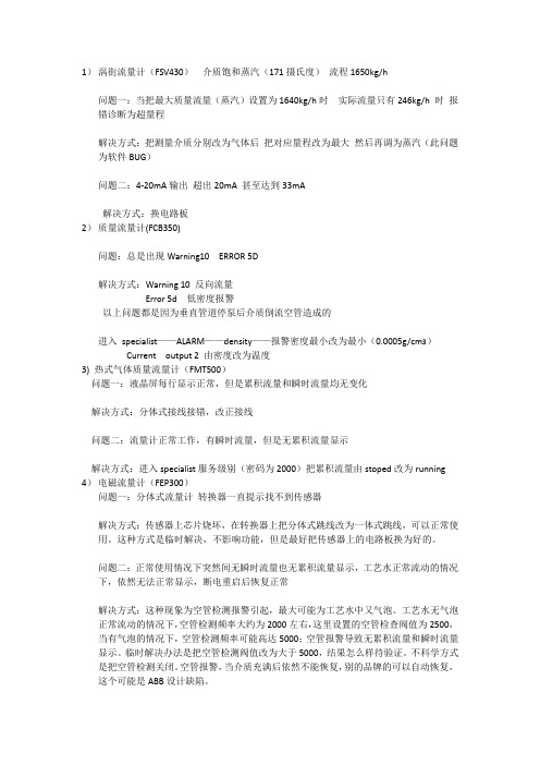
1)涡街流量计(FSV430)介质饱和蒸汽(171摄氏度)流程1650kg/h问题一:当把最大质量流量(蒸汽)设置为1640kg/h时实际流量只有246kg/h 时报错诊断为超量程解决方式:把测量介质分别改为气体后把对应量程改为最大然后再调为蒸汽(此问题为软件BUG)问题二:4-20mA输出超出20mA 甚至达到33mA解决方式:换电路板2)质量流量计(FCB350)问题:总是出现Warning10 ERROR 5D解决方式:Warning 10 反向流量Error 5d 低密度报警以上问题都是因为垂直管道停泵后介质倒流空管造成的进入specialist——ALARM——density——报警密度最小改为最小(0.0005g/cm3)Current output 2 由密度改为温度3) 热式气体质量流量计(FMT500)问题一:液晶屏每行显示正常,但是累积流量和瞬时流量均无变化解决方式:分体式接线接错,改正接线问题二:流量计正常工作,有瞬时流量,但是无累积流量显示解决方式:进入specialist服务级别(密码为2000)把累积流量由stoped改为running 4)电磁流量计(FEP300)问题一:分体式流量计转换器一直提示找不到传感器解决方式:传感器上芯片烧坏,在转换器上把分体式跳线改为一体式跳线,可以正常使用。
这种方式是临时解决,不影响功能,但是最好把传感器上的电路板换为好的。
问题二:正常使用情况下突然间无瞬时流量也无累积流量显示,工艺水正常流动的情况下,依然无法正常显示,断电重启后恢复正常解决方式:这种现象为空管检测报警引起,最大可能为工艺水中又气泡。
工艺水无气泡正常流动的情况下,空管检测频率大约为2000左右,这里设置的空管检查阀值为2500,当有气泡的情况下,空管检测频率可能高达5000;空管报警导致无累积流量和瞬时流量显示。
临时解决办法是把空管检测阀值改为大于5000,结果怎么样待验证。
- 1、下载文档前请自行甄别文档内容的完整性,平台不提供额外的编辑、内容补充、找答案等附加服务。
- 2、"仅部分预览"的文档,不可在线预览部分如存在完整性等问题,可反馈申请退款(可完整预览的文档不适用该条件!)。
- 3、如文档侵犯您的权益,请联系客服反馈,我们会尽快为您处理(人工客服工作时间:9:00-18:30)。
Zone 0, 1, 2, 21, 22
Zone 0, 1, 2, 21, 22
Class I Div. 1, Class I Div. 2, Zone 0, 1, 2, 20, 21
Class I Div. 1, Class I Div. 2, Zone 0, 1, 2, 20, 21
另询
一体型,分体型
选项 TE1" 加长变送器 " 的安装
图 9:T 介质 -50 º … 120 ºC(-58 … 248 º… 200(-58 … 392 ºF)1 带保温的安装 1 保温层
如果选择 TE1" 加长变送器 " 安装选项,流量计传感器保温如 图 11 所示。
图 10:T 介质 -50 º … 200(-58 … 392 ºF)的安装
液体测量精度 - 质量流量 - 体积流量 - 密度
- 温度 气体测量精度 接液材质 防护等级依照 EN 60529 待测介质允许的温度 认证与证书 1) - 防爆 ATEX/IECEx - 防爆 cFMus - 防爆其他认证 外壳
1)部分在准备中
标准型 FCB330
高精度型 FCB350
DN 10 ...200,PN 40 ... 100 DN 1/4" ...8" PN CL150 ...CL600 DN 10 ... 100 (1/4" ... 4") DIN 32676 (ISO 2852) BPE 三爪卡箍 DN 10 ... 100(1/4" ... 4")
图 1:垂直安装,可自排空
图 2:垂直安装,排放管(流向自上向下) 1 上游罐 | 2 流量计 | 3 孔板或缩径装置 | 4 阀门 | 5 下游罐
8 DS/FCB300-ZH Rev. C | CoriolisMaster FCB330, FCB350
液体测量时的水平安装
不易进行液体测量的安装位置 空气或气泡在测量管中的积聚将会导致误差增加,因此,进行 液体测量时应避免以下安装位置:
DIN 32676 (ISO 2852) BPE 三爪卡箍 DN 10 ... 100 (1/4" ... 4")
流速的 0.1 % 和 0.15 % (o. r.) 流速的 0.15 % (o. r.)
- 0.002 kg/l - 0.001 kg/l(可选) - 0.0005 kg/l(根据工况现场标定) 0.5 K 流速的 0.5 % (o. r.) 不锈钢 IP 65/67,NEMA 4X -50 ... 200 ºC (-58 ...392 ºF)
支撑 为了支撑流量计传感器的重量并确保测量不受外部不利因素影响 (例如,介质中的气泡),应将流量计传感器安装到坚固的管路上。 应对称安装两个支撑或吊钩并且保证和过程连接直接连接周边区 域无应力作用。
切断设备 为了实现系统零点调整,管路中需要安装切断设备: - 水平安装在出口侧 - 垂直安装在入口侧 如果可能,可同时在传感器的出口和入口侧安装切断设备。
择取决于电路连接方式。安装后,也可以更改保护类型。用户 可将数字输出设置为 NAMUR 输出
CoriolisMaster FCB330、FCB350 变送器尤其适用于以下情况: - 高精度的质量流量测量 - 可随时测量介质密度 - 介质组份随时变化 - 测量不导电介质或高粘度、含固体颗粒的液体时 - 批处理灌装应用
安装说明 安装要求 / 系统尺寸信息 CoriolisMaster FCB330、FCB350 适合安装在室内和室外。标准 设备采用 IP67 防护等级外壳。流量计传感器可双向测量,安装方 向没有限制。必须确保测量管始终完全充满液体。所有接液部件 必须保证洁净。
6 DS/FCB300-ZH Rev. C | CoriolisMaster FCB330, FCB350
CoriolisMaster FCB330, FCB350 | DS/FCB300-ZH Rev. C 11
CoriolisMaster FCB330,FCB350 科氏力质量流量计
流量计传感器设计
设计
图 12:FCB300 流量计传感器 1 一体型 2 分体型(无变送器)
公称直径和测量范围
公称直径 DN 15 (1/2") DN 25 (1") DN 50 (2") DN 80 (3") DN 100 (4") DN 150 (6")
我们建议安装旁通管路以确保满足这些条件,安装旁通管路 同时可以保证在运行时也可以进行调节。
图 8:旁通管路
图 7:振动阻尼安装
10 DS/FCB300-ZH Rev. C | CoriolisMaster FCB330, FCB350
介质温度对安装的影响 流量计的安装位置取决于被测介质的温度 T 介质,请注意以下安 装选项!
带数字信号处理器(DSP)的变送器 CoriolisMaster FCB330、FCB350 变送器整合了数字信号处理器 (DSP),能够进行高精度质量流量和密度测量。Coriolis 传感器 信号可以立即转换成数字数据,无需任何中间模拟信号转换步骤。
新型 DSP 变送器实现了出色的长期稳定性和可靠性,以及快速信 号处理。
产品样本 DS/FCB300-ZH Rev. C
CoriolisMaster FCB330,FCB350 科氏力质量流量计
4 线制,一体或者分体型 适用于液体和气体的流 量测量
适用于高精度质量流量和密度的测量并可同时测量温度和浓度 符合 NAMUR 标准 结构紧凑,节省安装空间 生命周期维护成本低 压损小,无可动部件,无磨损
入口部分 流量计传感器对前直管段没有要求。但是需要确保流量计传感器 附近的任何阀门、通路、视镜等不会形成气穴并且不影响流量计 传感器的振动。
分体型设计 确保正确分配流量计传感器和变送器。相对应的设备在铭牌上具 有相同的后几位数字,例如,X001 和 Y001 或者 X002 和 Y002。
压力损失 压力损失由介质的特性和流量决定。 您可以登录 /flow 来下载文档,帮助您计算压力损 失。
自排空设计
全面的防爆认证和卫生型认证
先进的变送器 - 操作方便 - 独一无二的传感器存储器功能可确保数据安全 - 浓度测量
CoriolisMaster FCB330,FCB350 科氏力质量流量计
流量计传感器和变送器性能概述
规格说明
FCBXXX 流量计传感器(一体型)
型号 过程连接 - 法兰 DIN 2501/EN 1092-1 - 法兰 ASME B16.5 - 螺纹连接 DIN 11851 - 三爪卡箍
2 DS/FCB300-ZH Rev. C | CoriolisMaster FCB330, FCB350
FCTXXX 变送器
外壳 电缆长度 电源 电流输出
脉冲输出 外部输出回零 外部累加器重置 顺 / 回流测量 通信协议 空管检测 自监控和诊断 现场显示器 / 累加器 流量和密度的现场优化 防护等级依照 EN 60529
流量计传感器和变送器的自诊断功能,结合绝对的零点稳定性, 可确保测量的精确性。
FCB330、FCB350 基于科里奥利原理。这种设计具有以下优点: - 节省空间,坚固设计 - 多种过程连接可选 - 两个独立的电流输出,用于测量质量或体积流量、密度或温度,
以及一个脉冲输出 - 数字输入和输出 - HART 通信协议 - 防爆认证。用户可以为输出电路选择 "i" 或 "e" 型保护;类型选
体积聚或形成冷凝,会影响 测量精度。 泵附近的安装 必须使用阻尼装置来保证流量计不受到管道强振动的干扰。阻尼 装置必须安装在流量计支撑点之外并且保证在切断装置之外。 不要把阻尼装置和流量计直接连接。
零点调节 在工作条件下零点调节前请确保: - 测量管完全充满介质 - 测量管内无气泡或空气(进行液体测量时) - 测量管内没有冷凝(进行气体测量时) - 测量管内的压力和温度适合正常操作条件
安装时应该考虑下面几个因素: - 首选流向如流量计传感器上的箭头所示。朝此方向的流动将被
表示为正向(可提供正 / 反向标定作为选项)。 - 测量管内出现气泡会增大错误测量的可能性,尤其在测量密度
时。因此,不能将传感器安装到测量系统中的最高位置,推荐 安装在较低位置,例如管道中 U 形部分底部(倒转)。 - 应避免流量计传感器的下游垂直管道过长,防止流量计排空。 - 流量计安装完成后,检查其是否受到机械应力影响。 - 检查流量计传感器是否与其他物体接触,不得将流量计传感器 连接到外壳上。 - 确保介质中溶解的任何气体不会逸出并且测量管始终完全充满, 因此,建议最小背压为 0.2 bar (2.9 psi)。 - 测量气体时,确保气体干燥且不含液体。 - 确保当测量管中出现真空或当处理低沸点液体时,操作压力不 低于相应的蒸汽压力。 - 不要将流量计传感器安装到强磁场附近(例如泵、电机、变压 器等)。 - 确保多个流量计传感器间无交叉干扰的风险。为防止交叉干扰, 应使流量计传感器相互间隔一定距离或者传感器之间的管道应 该分隔开。
一体型设计:IP 65/IP 67,NEMA 4X 分体型设计:IP 67,NEMA 4X
CoriolisMaster FCB330, FCB350 | DS/FCB300-ZH Rev. C 3
CoriolisMaster FCB330,FCB350 科氏力质量流量计
概述
设备描述 CoriolisMaster FCB330、FCB350 是一款高性价比的 ABB 质量流 量计,配有新型 DSP 变送器。 该设备可提供配有内部变送器的一体型设计和配有外部变送器的 分体型设计。 一体型设计节省了安装时间和布线带来的额外成本。可以在现场 直接查看流量信息,一体型流量计也可以直接装在系统设备中, 并可以节省更多空间。
