APTGT20H60T3G中文资料
艾特顿电源防御模块型号PDG23G0060E2ZN商品说明说明书

Eaton PDG23G0060E2ZNEaton Power Defense molded case circuit breaker, Globally Rated, Frame 2, Three Pole, 60A, 35kA/480V, PXR20 LSI w/ ZSI and Relays, No TerminalsEaton Power Defense molded case circuit breakerPDG23G0060E2ZN 78667920454288.9 mm 152.4 mm 104.6 mm 1.82 kg Eaton Selling Policy 25-000, one (1) year from the date of installation of theProduct or eighteen (18) months from thedate of shipment of the Product,whichever occurs first.RoHS Compliant UL 489CCC MarkedIEC 60947-2CSAProduct NameCatalog Number UPCProduct Length/Depth Product Height Product Width Product Weight WarrantyCompliancesCertifications60 AComplete breaker 2Three-polePD2 Global Class A PXR 20 LSI600 Vac600 VNo Terminals35 kAIC at 480 Vac 10 kAIC Icu @125 Vdc 18 kAIC @600V (UL/CSA)25 kAIC Icu/ 20 kAIC Ics/ 52.5 kAIC Icm @480V Brazil (IEC) 10 kAIC Icu @250 Vdc36 kAIC Icu/ 36 kAIC Ics/ 75.6 kAIC Icm @380-415V (IEC) 20 kAIC Icu/ 15/13 kAIC Ics/ 42 kAIC Icm @525V South Africa (IEC)8 kAIC Icu/ 4 kAIC Ics/ 16.8 kAIC Icm @690V (IEC) 30 kAIC Icu/ 22.5 kAIC Ics/ 63 kAIC Icm @440V (IEC) 35 kAIC @480V (UL)55 kAIC Icu/ 55 kAIC Ics/ 121 kAIC Icm @240V (IEC) 65 kAIC @240V (UL)60 AEaton Power Defense MCCB PDG23G0060E2ZN 3D drawing Amperage Rating Circuit breaker frame type Frame Number of poles Circuit breaker type Class Trip Type Voltage rating Voltage rating - max Terminals Interrupt rating Interrupt rating range Trip rating 3D CAD drawing packageApplication notesPower Xpert Protection Manager x64Consulting application guide - molded case circuit breakersPower Xpert Protection Manager x32BrochuresPower Defense technical selling bookletPower Defense brochurePower Defense molded case circuit breaker selection posterPower Defense molded case circuit breakers - Frame 2 product aid CatalogsPower Xpert Release trip units for Power Defense molded case circuit breakersMolded case circuit breakers catalogCertification reportsEU Declaration of Conformity - Power Defense molded case circuit breakersPDG4 CB reportPDG4 CCC certificationPower Defense Declaration concerning California’s Proposition 65PDG2 CB reportInstallation instructionsPower Defense Frame 2 global terminal shield, 3 pole - IL012330EN Power Defense Frame 2/3/4/5/6 voltage neutral sensor module wiring instructions – IL012316ENPower Defense Frame 2 tunnel terminal (aluminum), 150A, 3 pole instructions - IL012238EN H03Power Defense Frame 2 shunt trip UVR instructions - IL012130EN Power Defense Frame 2 clamp terminal (steel), 20A, 3 pole instructions - IL012246EN H03Power Defense Frame 2 screw terminal_end cap kit, 225A, 3 pole instructions - IL012258EN H01Power Defense Frame 2 Direct Rotary Handle Assy With Interlock Version Instructions (IL012138EN).pdfPower Defense Frame 2 tunnel terminal kits - PDG2X1TA225K instructions- IL012239EN H01Power Defense Frame 2 terminal kit - PDG2X3(2)(4)TA225RF instructions - IL012245EN H01Power Defense Frame 2 tunnel terminal (aluminum), 50A, 3 pole instructions - IL012236EN H03Power Defense Frame 1 IEC and Frame 2 Rotary Mechanism with NFPA Handle Attachment Instructions (IL012260EN).pdfPower Defense Frame 2 terminal kit - PDG2X3(2)(4)TA150RFinstructions - IL012244EN H01Power Defense Frame 2 Bell Alarm Switch Instructions (IL012154EN).pdf Power Defense Frame 2 box terminal (steel), 100A, 3 pole instructions - IL012234EN H03Power Defense Frame 2 tunnel terminal (aluminum), 100A, 3 pole instructions - IL012237EN H03Power Defense Frame 2 box terminal (aluminum), 225A, 3 pole instructions - IL012235EN H03Power Defense Frame 1-2-3-4 IP door barrier assembly instructions -IL012278ENPower Defense Frame 2 locking devices and handle block instructions - IL012149ENPower Defense Frame 2 multi wire connector kit -PDG2X3(2)(4)TA2253W instructions - IL012243EN H01Power Defense Frame 2 handle mech direct rotary handle instructions - IL012134ENPower Defense Frame 2 handle mech variable depth rotary handle instructions - IL012136ENPower Defense Frame 2 multi wire connector kit -PDG2X3(2)(4)TA2256W instructions - IL012242EN H01Power Defense Frame 2 PDG2 and PDC(E)9 breaker instructions -IL012106ENInstallation videosPower Defense Frame 2 Bell Alarm with PXR Animated Instructions.pdf.rh Power Defense Frame 2 withTMTU, Shunt Trip_UVR Animated Instructions.rhPower Defense Frame 2 TMTU Aux, Alarm, ST and UVR Animated Instructions.rhPower Defense Frame 2 Handle Mech Variable Depth Rotary Handle Animated Instructions.rhPower Defense Frame 2 Locking Devices and Handle Block Animated Instructions.pdf.rhMultimediaPower Defense Frame 2 Variable Depth Rotary Handle Mechanism Installation How-To VideoPower Defense Frame 2 Direct Rotary Handle Mechanism Installation How-To VideoPower Defense Frame 3 Variable Depth Rotary Handle Mechanism Installation How-To VideoPower Defense Frame 2 Aux, Alarm, Shunt Trip, and UVR How-To Video Power Defense Frame 5 Trip Unit How-To VideoPower Defense BreakersEaton Corporation plc Eaton House30 Pembroke Road Dublin 4, Ireland © 2023 Eaton. All Rights Reserved. Eaton is a registered trademark.All other trademarks areproperty of their respectiveowners./socialmediaEaton Power Defense for superior arc flash safety Power Defense molded case circuit breakers Power Defense Frame 6 Trip Unit How-To Video Eaton Specification Sheet - PDG23G0060E2ZN Power Defense time current curve Frame 2 - PD2Selling Policy 25-000 - Distribution and Control Products and Services Making a better machineIntelligent circuit protection yields space savingsMolded case and low-voltage power circuit breaker health Single and double break MCCB performance revisited Intelligent power starts with accurate, actionable data Molded case and low-voltage breaker health Safer by design: arc energy reduction techniquesSpecifications and datasheetsTime/current curvesWarranty guidesWhite papers。
拓顿(Eaton)电气断路器电流传感器和ating插座替换套件说明书
Instructional Leaflet IL2C13762H01
Effective January 2011
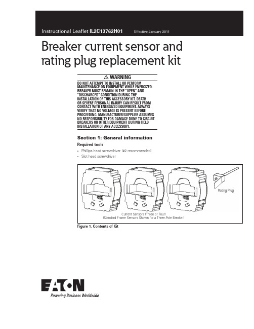
Figure 4. Step 6
eaton corporation
3
InstruChain Management is a registered trademark of Eaton Corporation.
All other trademarks are property of their respective owners.
Instructional Leaflet IL2C13762H01
Effective January 2011
Breaker current sensor and rating plug replacement kit
warning
Do NOT attempt to install or perform maintenance on equipment while energized. Breaker must remain in the “OPEN” and ”DISCHARGED” condition during the installation of this accessory kit. Death or severe personal injury can result from contact with energized equipment. Always verify that no voltage is present before proceeding. Manufacturer/Supplier assumes no responsibility for damage done to circuit breakers or other equipment during field installation of any accessory.
GeForce 6100 AMz 主板 说明书

第五章:帮助信息................................................................................21
6.1
驱动程序安装注意事项............................................................................ 21
GeForce 6100 AM2
FCC Information and Copyright
This equipment has been tested and found to comply with the limits of a Class B digital device, pursuant to Part 15 of the FCC Rules. These limits are designed to provide reasonable protection against harmful interference in a residential installation. This equipment generates, uses and can radiate radio frequency energy and, if not installed and used in accordance with the instructions, may cause harmful interference to radio communications. There is no guarantee that interference will not occur in a particular installation.
艾特顿电路保护器系列G JGX305036Z1 说明书
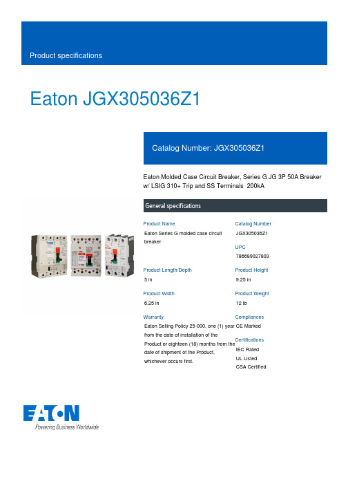
Eaton JGX305036Z1Eaton Molded Case Circuit Breaker, Series G JG 3P 50A Breaker w/ LSIG 310+ Trip and SS Terminals 200kAGeneral specificationsEaton Series G molded case circuit breakerJGX305036Z17866890278035 in9.25 in 6.25 in 12 lb Eaton Selling Policy 25-000, one (1) year from the date of installation of theProduct or eighteen (18) months from thedate of shipment of the Product,whichever occurs first.CE Marked IEC RatedUL ListedCSA CertifiedProduct NameCatalog Number UPCProduct Length/Depth Product Height Product Width Product Weight WarrantyCompliancesCertificationsEaton Corporation plc Eaton House30 Pembroke Road Dublin 4, Ireland © 2023 Eaton. All Rights Reserved. Eaton is a registered trademark.All other trademarks areproperty of their respective owners./socialmedia200 kAIC Complete breaker 50 A 310+ electronic LS Three-poleApplication of Multi-Wire Terminals for Molded Case Circuit Breakers Application of Tap Rules to Molded Case Breaker Terminals Series G MCCB quick selectorComprehensive circuit protection for control panel applications StrandAble terminals product aidCurrent limiting molded case circuit breaker module product aid Circuit breaker motor operators product aid Motor protection circuit breakers product aid Multi-wire lugs product aidPower metering and monitoring with Modbus RTU product aid Molded case circuit breakers providing higher levels of selective coordination product aidCurrent limiting molded case circuit breaker module for series G, JG and CLHigh performance operating handles for Series G circuit breakers product aidPlug-in adapters for molded case circuit breakers product aid Breaker service centers Molded case circuit breakers catalog Eaton Specification Sheet - JGX305036Z1MOEM MCCB product selection guide NG and ND-Frame molded case circuit breakersInterrupt rating TypeAmperage Rating Trip TypeNumber of poles Application notesBrochuresCatalogsSpecifications and datasheets。
高科特实际产品说明书
4
Specifications are subject to change without notice (21.06.2021)
Solid State Relays Accessories, Screw Kits Types SRWKIT…
Ordering Key
Screw Kit Screw size Screw length
0.5 Nm -20° to + 70°C [-4 to +158°F] -40° to + 100°C [-40° to +212°F] DIN EN 50022, 50035
DIN Adaptor for 1-phase SSRs
DIN rail adaptor module for mounting the 1-phase SSR series RA, RD, RM, RS and RAM directly on DIN rail.
Type
UL style 2547 UL style 2464 UL style 2464 UL style 2464 UL style 2464 UL style 2464
Cable size
0.14mm2 0.14mm2 0.14mm2 0.25mm2 0.14mm2 0.14mm2
Termination
- Width x Height x Thickness = 35 x 43 x 0.25 mm
- Packing qty. 50 pcs.
RZHT
- Graphite thermal pad for RZ3 series with adhesive on one side
- Width x Height x Thickness = 70 x 77 x 0.25 mm
华为电源柜 用户手册

TP48600T-N20A3
用户手册
文档版本 发布日期
01 2016-01-04
华为技术有限公司
版权所有 © 华为技术有限公司 2016。 保留一切权利。
非经本公司书面许可,任何单位和个人不得擅自摘抄、复制本文档内容的部分或全部,并不得以任何形式传 播。
用于警示潜在的危险情形,若不避免,可能会导致人员死亡或严 重的人身伤害。
用于警示潜在的危险情形,若不避免,可能会导致中度或轻微的 人身伤害。
用于传递设备或环境安全警示信息,若不避免,可能会导致设备 损坏、数据丢失、设备性能降低或其它不可预知的结果。 “注意”不涉及人身伤害。
用于突出重要/关键信息、最佳实践和小窍门等。 “说明”不是安全警示信息,不涉及人身、设备及环境伤害信息。
1 安全注意事项.................................................................................................................................. 1
1.1 通用安全注意事项 ..................................................................................................................................................... 1 1.2 电气安全 ..................................................................................................................................................................... 2 1.3 电池安全 ..................................................................................................................................................................... 2 1.4 布线要求 ..................................................................................................................................................................... 4 1.5 机械安全 ..................................................................................................................................................................... 4
深圳市易驱电气有限公司GT20系列变频器用户手册说明书精选全文完整版

前言感谢您购买深圳市易驱电气有限公司开发生产的GT20系列变频器!GT20系列变频器是一款通用高性能变频器,具备低频力矩大、电机参数自辨识、最优加减速控制等先进的控制性能;具备满足不同工艺要求的功能,如多段速控制、简易PLC控制、PI控制、定长控制、下垂控制、自动节能运行、灵活的频率给定方式,多样的频率组合方式以及组合算法等一系列实用的功能。
可用于机床、线缆、纺织、造纸、食品、包装、化工、市政工程等自动化生产设备的驱动,满足不同工业设备对性能、功能的需求。
在使用本变频器之前,请变频器使用者及相关技术人员仔细阅读本手册,以确保能正确安装和操作变频器,使变频器发挥其最佳性能。
本用户手册如有改动,请以新版为准,恕不另行通知。
高性能变频器用户手册资料版本:V1.1本产品执行标准:本产品的设计、生产制造参照了最新版本的国家标准(GB或GB/T)及国际电工委员会标准(IEC)及国际单位制(SI),其相关部分技术参数可以满足的国家标准(GB或GB/T)及国际电工委员会标准(IEC)标准要求。
主要依据标准:GB/T12668.2-2002调速电气传动系统第2部分一般要求----低压交流变频电气传动系统额定值的规定GB12668.3-2012调速电气传动系统第3部分----产品电磁兼容性标准及其特定的试验方法GB12668.501-2013调速电气传动系统第5部分安全要求电气、热和能量GB/T2423.1-2008电工电子产品环境试验第1部分----试验方法试验A:低温GB/T2423.2-2008电工电子产品环境试验第2部分----试验方法试验B:高温GB/T2423.3-2016电工电子产品环境试验规程试验Cab----恒定湿热试验GB/T2423.4-2008电工电子产品环境试验规程试验Db----交变湿热GB/T2423.22-2012环境试验第2部分:试验方法试验N:温度变化GB/T2423.7-2018环境试验第2部分:试验方法试验Ec:粗率操作造成的冲击GB/T4798.1-2005电工电子产品应用环境条件第1部分:贮存GB/T4798.2-2008电工电子产品应用环境条件第2部分:运输GB/T4798.3-2007电工电子产品应用环境条件第3部分:有气候防护场所固定使用读者对象本使用说明书适合以下人员阅读变频器安装人员、工程技术人员(电气工程师、电气操作工等)、设计人员等请确保此用户手册到达最终用户手中。
Dell PowerEdge M620 Systems 用户手册说明书

Dell PowerEdge M620 Systems(适用于 Dell PowerEdge VRTX 机柜)用户手册管制型号: HHB管制类型: HHB003注、小心和警告注: “注”表示可以帮助您更好地使用计算机的重要信息。
小心: “小心”表示可能会损坏硬件或导致数据丢失,并说明如何避免此类问题。
警告: “警告”表示可能会造成财产损失、人身伤害甚至死亡。
版权所有© 2014 Dell Inc. 保留所有权利。
本产品受美国、国际版权和知识产权法律保护。
Dell™和 Dell 徽标是 Dell Inc. 在美国和 / 或其他管辖区域的商标。
所有此处提及的其他商标和产品名称可能是其各自所属公司的商标。
2014–10Rev. A01目录1 关于系统 (7)简介 (7)前面板部件和指示灯 (8)使用 USB 软盘或 USB DVD/CD 驱动器 (8)硬盘驱动器功能部件 (8)您可能需要的其他信息 (9)2 使用系统设置程序和引导管理器 (11)选择系统引导模式 (12)进入系统设置 (12)响应错误消息 (12)使用系统设置程序导航键 (12)系统设置选项 (12)系统设置程序主屏幕 (13)系统 BIOS 屏幕 (13)System Information(系统信息)屏幕 (14)Memory Settings(内存设置)屏幕 (14)Processor Settings(处理器设置)屏幕 (15)SATA Settings(SATA 设置)屏幕 (16)Boot Settings(引导设置)屏幕 (16)Integrated Devices(集成设备)屏幕 (17)Serial Communications(串行通信)屏幕 (18)系统配置文件设置屏幕 (18)System Security(系统安全)屏幕 (19)Miscellaneous Settings(其它设置) (20)系统和设置密码功能 (21)分配系统密码和/或设置密码 (21)使用系统密码保护系统安全 (22)删除或更改现有系统密码和/或设置密码 (22)在已启用设置密码的情况下进行操作 (22)进入 UEFI 引导管理器 (23)使用引导管理器导航键 (23)Boot Manager(引导管理器)屏幕 (23)UEFI Boot(UEFI 引导)菜单 (24)嵌入式系统管理 (24)iDRAC 设置公用程序 (24)进入 iDRAC 设置公用程序 (25)3 安装服务器模块组件 (26)建议工具 (26)安装和卸下服务器模块 (26)卸下服务器模块 (26)安装服务器模块 (28)打开与合上服务器模块 (28)打开服务器模块 (28)合上服务器模块 (29)服务器模块内部 (30)冷却导流罩 (30)卸下冷却导流罩 (30)安装冷却导流罩 (31)系统内存 (31)一般内存模块安装原则 (33)模式特定原则 (34)内存配置示例 (35)卸下内存模块 (38)安装内存模块 (39)PCIe 夹层卡 (40)卸下 PCIe 夹层卡 (40)安装 PCIe 夹层卡 (41)管理提升卡 (42)更换 SD 卡 (42)内部 USB 盘 (43)SD vFlash 卡 (43)装回 SD vFlash 卡 (43)网络子卡/LOM 提升卡 (44)卸下网络子卡/LOM 提升卡 (44)安装网络子卡/LOM 提升卡 (45)处理器 (45)卸下处理器 (46)安装处理器 (48)硬盘驱动器 (49)硬盘驱动器/SSD 安装原则 (50)卸下硬盘驱动器/SSD (50)安装硬盘驱动器/SSD (50)进行硬盘驱动器维修前的关机程序 (51)配置引导驱动器 (51)从硬盘驱动器/SSD 托盘中卸下硬盘驱动器/SSD (51)将硬盘驱动器/SSD 安装到硬盘驱动器/SSD 托盘中 (52)硬盘驱动器/SSD 背板 (52)卸下硬盘驱动器/SSD 背板 (52)安装硬盘驱动器/SSD 背板 (53)系统板 (54)卸下系统板 (54)安装系统板 (55)NVRAM 备用电池 (56)更换 NVRAM 备用电池 (56)存储控制器卡 (57)卸下存储控制器卡 (57)安装存储控制器卡 (58)4 系统故障排除 (59)安全第一—为您和您的系统着想 (59)系统内存故障排除 (59)硬盘驱动器故障排除 (59)USB 设备故障排除 (60)内部 SD 卡故障排除 (60)处理器故障排除 (61)系统板故障排除 (61)NVRAM 备用电池故障排除 (61)5 使用系统诊断程序 (63)Dell Online Diagnostics (63)Dell 嵌入式系统诊断程序 (63)何时使用 Embedded System Diagnostics(嵌入式系统诊断程序) (63)运行嵌入式系统诊断程序 (63)从外部介质运行嵌入式系统诊断程序 (64)系统诊断程序控件 (64)6 跳线和连接器 (65)系统板跳线设置 (65)系统板连接器 (66)禁用已忘记的密码 (67)7 技术规格 (68)8 系统消息 (71)LCD 状态信息 (71)查看 LCD 信息 (71)删除 LCD 消息 (71)系统错误消息 (71)警告信息 (141)诊断消息 (142)警报消息 (142)9 获得帮助 (143)联系 Dell (143)1关于系统简介本说明文件提供了有关 Dell PowerEdge M620 服务器模块的信息,该模块专为 PowerEdge VRTX 机柜配置,并且可以通过服务器模块上的标记为PCIe的标签来进行识别。
APT60S20B2CTG;中文规格书,Datasheet资料
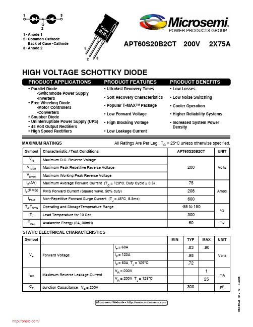
053-6043 R e v C 7-2006STATIC ELECTRICAL CHARACTERISTICSMAXIMUM RATINGSAll Ratings Are Per Leg: T C = 25°C unless otherwise specified.PRODUCT BENEFITS•Low Losses•Low Noise Switching •Cooler Operation•Higher Reliability Systems •Increased System PowerDensity•Ultrafast Recovery Times •Soft Recovery Characteristics •Popular T-MAX™ Package •Low Forward Voltage •High Blocking Voltage •Low Leakage CurrentHIGH VOLTAGE SCHOTTKY DIODE•Parallel Diode -Switchmode Power Supply -Inverters•Free Wheeling Diode -Motor Controllers -Converters •Snubber Diode•Uninterruptible Power Supply (UPS)•48 Volt Output Rectifiers •High Speed RectifiersSymbolV FI RM C TUNITVoltsmApFMINTYPMAX.83.90.98.72125300Forward VoltageMaximum Reverse Leakage Current Junction Capacitance, V R = 200VI F = 60AI F = 120AI F = 60A, T J = 125°CV R = 200VV R = 200V, T J = 125°CCharacteristic / Test Conditions Maximum D.C. Reverse VoltageMaximum Peak Repetitive Reverse Voltage Maximum Working Peak Reverse VoltageMaximum Average Forward Current (T C = 123°C, Duty Cycle = 0.5)RMS Forward Current (Square wave, 50% duty)Non-Repetitive Forward Surge Current (T J = 45°C, 8.3ms)Operating and StorageTemperature Range Lead Temperature for 10 Sec.Avalanche Energy (2A, 30mH)Symbol V R V RRM V RWM I F (AV)IF (RMS)I FSM T J ,T STGT L E VALUNITVoltsAmps°C mJ APT60S20B2CT20075208600-55 to 1503006021-Anode 12-Common CathodeBack of Case -Cathode 3-Anode 2APT60S20B2CT 200V 2X75AMicrosemi Website - /APT60S20B2CTDYNAMIC CHARACTERISTICS053-6043 R e v C 7-2006THERMAL AND MECHANICAL CHARACTERISTICSMicrosemi reserves the right to change, without notice, the specifications and information contained herein.Characteristic / Test Conditions Junction-to-Case Thermal Resistance Junction-to-Ambient Thermal Resistance Package WeightSymbol R θJC R θJA W TMINTYPMAX.30400.225.9UNIT °C/W ozgZ θJ C , T H E R M A L I M P E D A N C E (°C /W )RECTANGULAR PULSE DURATION (seconds)FIGURE 1a. MAXIMUM EFFECTIVE TRANSIENT THERMAL IMPEDANCE, JUNCTION-TO-CASE vs. PULSE DURATION0.350.300.250.200.150.100.050FIGURE 1b, TRANSIENT THERMAL IMPEDANCE MODELDissipated Power(Watts)sink to ambient, etc. Set to zero when modeling only the case to junction./053-6043 R e v C 7-2006APT60S20B2CTTYPICAL PERFORMANCE CURVESQ r r , R E V E R S E R E C O V E R Y C H A R G E I F , F O R W A R D C U R R E N T (n C )(A )I R R M , RE V E R S E R E C O V E R Y CU R R E N T t r r , R E V E R S E R E C O V E R Y T I M E (A )(n s)20018016014012010080604020018001600140012001000800600400200012010080604020035302520151050V F , ANODE-TO-CATHODE VOLTAGE (V)-di F /dt, CURRENT RATE OF CHANGE(A/µs)Figure 2. Forward Current vs. Forward VoltageFigure 3. Reverse Recovery Time vs. Current Rate of Change-di F /dt, CURRENT RATE OF CHANGE (A/µs)-di F /dt, CURRENT RATE OF CHANGE (A/µs)Figure 4. Reverse Recovery Charge vs. Current Rate of ChangeFigure 5. Reverse Recovery Current vs. Current Rate of Change1.21.00.80.60.40.20.03500300025002000150010005001101002001101001000220025020015010050100501051C J , J U N C T I O N C A P A C I T A N C E K f ,D Y N A M I C P A R A ME T E R S (pF )(N o r m a l i z e d t o 700A /µs )P E A K A V A L A N C H E C U R R E N T I F (A V ) (A )(A )T J , JUNCTION TEMPERATURE (°C)Case Temperature (°C)Figure 6. Dynamic Parameters vs. Junction TemperatureFigure 7. Maximum Average Forward Current vs. CaseTemperatureV R , REVERSE VOLTAGE (V)Time in Avalanche (µs)Figure 8. Junction Capacitance vs. Reverse VoltageFigure 9. Single Pulse UIS SOA/APT60S20B2CT053-6043 R e v C 7-200651234di F /dt - Rate of Diode Current Change Through Zero Crossing.I F - Forward Conduction CurrentI RRM - Maximum Reverse Recovery Current.t rr - ReverseR ecovery Time, measured from zero crossing where Q rr - Area Under the Curve Defined by I RRM and t rr .line through I RRM and 0.25 I RRM passes through zero.Figure 9. Diode Test CircuitFigure 10, Diode Reverse Recovery Waveform and DefinitionsVDimensions in Millimeters and (Inches)T-MAX TM (B2) Package OutlineMicrosemi’s products are covered by one or more of U.S.patents 4,895,810 5,045,903 5,089,434 5,182,234 5,019,522 5,262,336 6,503,7865,256,583 4,748,103 5,283,202 5,231,474 5,434,095 5,528,058 and foreign patents. US and Foreign patents pending. All Rights Reserved./分销商库存信息: MICROSEMIAPT60S20B2CTG。
最新APT2000TC中文说明书汇总

A P T2000T C中文说明书一、组装装箱单和开箱小心开箱,检查是否有运输过程中的破坏及元件是否完好。
箱内包括:—变送器的前面单元—后盖—设备罩—操作手册包内包括:1、2个密封塞2、5个六角螺帽3、3个PG电缆4、1个橡胶垫5、1个PG塞6、4个螺丝7、1个插销8、3个线夹9、3个堵孔塞 10、3个密封垫片 11、1个垫片 12、1个跳线器图1 组装图图2 安装尺寸图图3 P/N 51205988-001 管道安装件图4 P/N 51205989-001用于墙装及管道安装的护杆帽图5 APT4000PH 变送器安装信息⑴、给多芯电缆确定剥离器长度⑵、用螺丝刀撬起端子排⑶、敷设变送器电缆⑷、连接回路电流电缆⑸、敷设探头及温度电极盖⑹、用螺丝刀撬出端子排的区域⑺、连接端子排二、安装、接线及投运适用范围APT2000TC 变送器适用于化工、造纸、生物、食品、制药、废水等方面的电导率和温度的测量。
可以用在现场和集控室中。
APT2000TC-0(H)-00可以在安全和危险至DIV2级的工况下运行,在变送器与电源接线前,确保在安全工况下输出不超过40DC,危险情况下小于30DC。
APT2000TC-0(H)-IS 变送器适用于在危险区域(DV1)级的工况下运行。
在与电源连接前,确保它是个合适的仪器。
APT2000TC-0(H)-IS 变送器的测量输入如何欧洲的0级标准,然而,确保本仪器符合本国的有关0级的相关制度。
在0级工况下,变送器本身不符合此标准。
电导率变送器的总则图六、APT2000TC变送器的系统功能①玻璃及参考电极输入②温度电极输入、③从变送器的变送电源、输出信号、回路电流。
,对于APT2000TC-H,变送器为通讯。
④(对于APT2000TC-0(H)-IS变送器,符合CENELEC/ATEX要求;FM/CSA没要求)等位连接端子排功用图7、APT2000TC-0(H)-00变送器的端子排功用图8、APT2000TC-0(H)-IS变送器的端子排功用安装及投运安装和投运必须遵守此手册和当地和国家的相关的规章制度,确保技术规范和输入限额。
CAN通讯说明书

德威特自动化系统软件系列DVP-600系列主机通讯控制卡系统使用说明书北京德威特电力系统自动化集团北京中关村中国科学院电工研究所科技公寓目录第一部分硬件 (5)一、概述 (5)二、特点 (5)1、专用的智能通讯卡无须主机再做通讯工作 (5)2、通讯硬件可靠性高、抗干扰能力强 (5)3、通讯软件可靠性高、响应快、通用性强 (5)三、功能 (5)四、技术参数 (6)CAN 网: (6)RS—485 网: (6)五、硬件原理及结构 (7)1.通讯卡原理 (7)2.通讯卡结构组成 (8)2.0 通讯卡平面布置图 (图1-5-2) (8)2.1 主要元件 (9)2.2 接口管角定义 (9)六、通讯板号整定 (9)七、双口RAM在PC机I/O空间的地址整定及使用 (10)八、通讯卡PC机中断号整定 (11)第二部分通讯协议 (12)一、协议概述 (12)二、双口RAM地址分配表 (12)1、通讯协议地址表 (12)1.1 分类表 (12)1.2 双口 RAM 详细地址分配表 (12)2、双口RAM地址分配表 (15)2.0 装置报警信息地址分配表 (15)2.1 装置登记次数地址分配表 (15)2.2 装置登记信息数据状态地址分配表 (15)2.3 装置(实时+定值)数据地址分配表 (16)三、通讯协议使用说明 (16)1.通讯工作原理 (16)1.1 通讯卡 (16)1.1.1 通讯卡本身任务 (17)1.1.2 主机下发任务 (17)1.2 主机 (17)2.装置登记管理及数据结构 (17)2.1 登记记录 (17)2.2 登记次数 (18)3.命令与应答数据结构及使用原理 (18)3.1 命令帧数据结构 (18)北京德威特电力系统自动化集团2微机保护通讯网使用说明3.2 应答帧数据结构 (19)3.3 命令分类及应答 (20)3.4 命令与应答的使用 (21)3.5 命令分析 (22)3.5.1 保护出口 (22)3.5.2 修改定值 (22)3.5.3 遥控操作 (23)3.5.4 信号复归 (23)3.5.5 广播对时 (23)4. 主机从机数据传送接收原理及数据结构 (24)5. 网络报警原理及数据结构 (24)5.1 报警帧结构 (24)5.2 报警帧类型及数据分析 (25)5.2.1报警类型 (25)5.2.2报警数据 (26)5.3 报警数据区 (26)5.4 报警数据读取方法 (27)6.通讯卡对时管理 (27)7. 通讯卡中断管理 (28)7.1 中断内容 (28)7.2 报警中断与报警数据区关系 (28)8. 装置数据区数据结构及使用 (28)8.1 装置数据区数据结构 (28)8.2 装置数据区的使用 (28)第三部分通讯数据定义及转换 (30)一、监控数据定义及转换 (30)a、普通电流 (30)b、零序电流 (30)c、电压 (30)d、时间 (30)e、频率 (30)二、保护数据定义及转换 (31)a、普通电流 (31)b.1、零序电流(仅指电容器保护中I0d和cI0) (31)b.2、零序电流(一般I0d) (31)c、电压 (31)d、时间 (31)e、频率 (32)f、系数(指变压器保护中,比率系数cdb和谐波系数cdp) (32)g、突变量(指变压器保护中,突变量启动值dII) (32)h、滑差 (32)i、检同期 (33)j、保护投退 (33)北京德威特电力系统自动化集团 3第四部分使用维护 (36)一、通讯网络连接调试 (36)1.1 网络互连 (36)1.1.1 系统组成 (36)1.1.2 注意事项 (36)1.2 地址整定 (37)1.2.1 通讯卡板号整定 (37)1.2.2 通讯卡 I/O 地址整定 (37)1.2.3 通讯卡中断号整定 (37)1.2.4 保护监控装置通讯编号整定 (37)1.3 现场调试(包括对通讯硬件和软件的调试) (37)二、故障处理 (38)1、网络构造完成后不能通讯 (38)2、可以通讯,但通讯不稳定可靠 (38)3、大部分站通讯正常,但个别站通讯不正常 (38)三、注意事项 (39)第五部分资料附录 (40)一、DVP600系列保护监控装置双口RAM分配表 (40)二、DVP600系列保护监控装置航空插头端子图 (42)附录《DVP600系列保护监控装置CAN总线航空插头端子图》 (42)附录特例《DVP601保护监控装置CAN总线航空插头端子图》 (42)北京德威特电力系统自动化集团4微机保护通讯网使用说明第一部分硬件一、概述本通讯卡是与微机保护监控系统配套使用;硬件高可靠性,连接方便,通讯速率高;通讯协议简单可靠且智能化,数据容量大;并可多卡同时上网,自动以单主机多从机方式运行,安全可靠。
APT-6000T 综合通信管理单元用户手册V1.00

APT-6000T 综合通信管理单元用户手册珠海市阿普顿电气有限公司2019年3月编制:罗晓培校核:王振审批:张晓易文件编号:APT/ZDH-2019-03 版本号:V1.00出版日期:2019 年 03月版权所有:珠海市阿普顿电气有限公司注:我公司保留对此说明书修改的权利。
如果产品与说明书有不符之处,请您及时与我公司联系,我们将为您提供相应的服务。
一、特点及技术参数1.1 概述本装置采用高速高性能32位A8处理器、高精度电压变换器、大屏幕液晶显示器,内置实时多任务操作系统,使装置运行速度快、抗干扰性能强、整定与查询非常方便。
APT-6000T 综合通信管理单元内置4个串口满足配网环境、无线测温、局放、线损采集等通讯监测功能,内置4个光电混用RJ45接口,满足下行智能分布式配电自动化终端通讯功能,具有两段母线PT电压测控功能。
串口及光电混用RJ45接口两者相互独立,可同时通讯,互不干扰。
APT-6000T 综合通信管理单元在下行方向采用MODBUS、101、104规约与智能分布式配电自动化终端进行通讯。
在上行方向既可采用RS232串口连接GPRS模块与后台主站进行101规约通讯,又可采用装置的RJ45网络接口与后台主站进行104规约通讯。
1.2 特点1.采用集成32位ARM核的MCU,该MCU运行速度快、数据处理能力强,资源非常丰富。
采用单芯片解决方案,与外部设备的接口采用互感器、继电器、光电耦合器等多种隔离措施与保护措施,使元器件少,抗干扰能力强,运行稳定可靠。
2.采用高性能、高可靠性的开关电源,宽范围通用输入,提供三种工作电源可选择,分为85-265VAC/DC、24VDC、48VDC。
电源输入端采用多重抗干扰滤波措施及防雷击保护回路,各种滤波电容均采用长寿命、耐高温、高频低阻电解电容,高频变压器采用双层屏蔽措施,确保能长期稳定可靠工作。
3.控制器内部采用高精度的时钟芯片,芯片内部集成有高精度低温漂晶振,时钟即使在掉电后也能准确走时十年以上,时钟的精度由芯片厂家保证年误差不超过2 分钟,解决了通常配电自动化终端单独运行时间不准的问题,使其能准确记录各种故障信息。
APT100GN60B2(G) 电子器件说明书
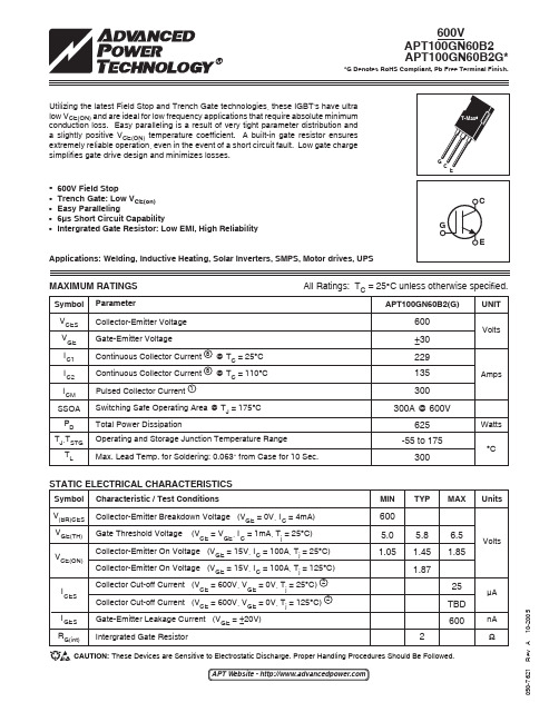
050-7621 R e v A 10-2005MAXIMUM RATINGSAll Ratings: TC = 25°C unless otherwise specified.STATIC ELECTRICAL CHARACTERISTICSCharacteristic / Test ConditionsCollector-Emitter Breakdown Voltage (V GE = 0V, I C = 4mA)Gate Threshold Voltage (V CE = V GE , I C = 1mA, T j = 25°C)Collector-Emitter On Voltage (V GE = 15V, I C = 100A, T j = 25°C)Collector-Emitter On Voltage (V GE = 15V, I C = 100A, T j = 125°C)Collector Cut-off Current (V CE = 600V, V GE = 0V, T j = 25°C) 2Collector Cut-off Current (V CE = 600V, V GE = 0V, T j = 125°C) 2Gate-Emitter Leakage Current (V GE = ±20V)Intergrated Gate ResistorSymbol V (BR)CES V GE(TH)V CE(ON)I CES I GES R G(int)UnitsVoltsµAnA ΩSymbol V CES V GE I C1I C2I CM SSOA P D T J ,T STGT LAPT100GN60B2(G)600±30229135300300A @ 600V625-55 to 175300UNIT VoltsAmpsWatts °CParameterCollector-Emitter Voltage Gate-Emitter VoltageContinuous Collector Current 8 @ T C = 25°C Continuous Collector Current 8 @ T C = 110°C Pulsed Collector Current 1Switching Safe Operating Area @ T J = 175°C Total Power DissipationOperating and Storage Junction Temperature RangeMax. Lead Temp. for Soldering: 0.063" from Case for 10 Sec.APT Website - CAUTION: These Devices are Sensitive to Electrostatic Discharge. Proper Handling Procedures Should Be Followed.Utilizing the latest Field Stop and Trench Gate technologies, these IGBT's have ultralow V CE(ON) and are ideal for low frequency applications that require absolute minimum conduction loss. Easy paralleling is a result of very tight parameter distribution and a slightly positive V CE(ON) temperature coefficient. A built-in gate resistor ensures extremely reliable operation, even in the event of a short circuit fault. Low gate charge simplifies gate drive design and minimizes losses.• 600V Field Stop• Trench Gate: Low V CE(on) • Easy Paralleling• 6µs Short Circuit Capability•Intergrated Gate Resistor: Low EMI, High ReliabilityApplications: Welding, Inductive Heating, Solar Inverters, SMPS, Motor drives, UPSMIN TYP MAX 6005.0 5.86.5 1.05 1.45 1.851.87 25 TBD 6002050-7621 R e v A 10-2005APT100GN60B2(G)1 Repetitive Rating: Pulse width limited by maximum junction temperature.2 For Combi devices, I ces includes both IGBT and FRED leakages3 See MIL-STD-750 Method 3471.4 E on1 is the clamped inductive turn-on energy of the IGBT only, without the effect of a commutating diode reverse recovery current adding to the IGBT turn-on loss. Tested in inductive switching test circuit shown in figure 21, but with a Silicon Carbide diode.5 E on2 is the clamped inductive turn-on energy that includes a commutating diode reverse recovery current in the IGBT turn-on switchingloss. (See Figures 21, 22.)6 E off is the clamped inductive turn-off energy measured in accordance with JEDEC standard JESD24-1. (See Figures 21, 23.)7 R G is external gate resistance, not including R G(int) nor gate driver impedance. (MIC4452)8 Continuous current limited by package pin temperature to 100A.APT Reserves the right to change, without notice, the specifications and information contained herein.THERMAL AND MECHANICAL CHARACTERISTICSUNIT °C/W gmMIN TYP MAX.21 N/A5.9CharacteristicJunction to Case (IGBT)Junction to Case (DIODE)Package WeightSymbol R θJC R θJC W TDYNAMIC CHARACTERISTICSSymbol C ies C oes C res V GEP Q g Q ge Q gc SSOA SCSOA t d(on)t rt d(off)t f E on1E on2E off t d(on)t r t d(off)t f E on1E on2E off Test Conditions Capacitance V GE = 0V, V CE = 25Vf = 1 MHz Gate Charge V GE = 15VV CE = 300V I C = 100A T J = 175°C, R G = 4.3Ω 7, V GE =15V, L = 100µH,V CE = 600V V CC = 600V, V GE = 15V, T J = 125°C, R G = 4.3Ω 7Inductive Switching (25°C)V CC = 400V V GE = 15V I C = 100AR G= 1.0Ω 7T J = +25°CInductive Switching (125°C)V CC = 400V V GE = 15V I C = 100A R G= 1.0Ω 7T J = +125°CCharacteristic Input Capacitance Output CapacitanceReverse Transfer Capacitance Gate-to-Emitter Plateau Voltage Total Gate Charge 3 Gate-Emitter ChargeGate-Collector ("Miller") Charge Switching Safe Operating Area Short Circuit Safe Operating Area Turn-on Delay Time Current Rise Time Turn-off Delay Time Current Fall TimeTurn-on Switching Energy 4Turn-on Switching Energy (Diode) 5Turn-off Switching Energy 6 Turn-on Delay Time Current Rise Time Turn-off Delay Time Current Fall TimeTurn-on Switching Energy 4 4Turn-on Switching Energy (Diode) 55Turn-off Switching Energy 66MIN TYPMAX6000 560 200 9.5 600 45340 300631 65 310 55 4750 5095267531 65 350 85 5000 62553300UNIT pF V nCAµsnsµJns µJ050-7621 R e v A 10-2005TYPICAL PERFORMANCE CURVESV G S (T H ), T H R E S H O L D V O L T A G EV C E , C O L L E C T O R -T O -E M I T T E R V O L T A G E (V )I C , C O L L E C T O R C U R R E N T (A )I C , C O L L E C T O R C U R R E N T (A )(N O R M A L I Z E D )I C , D C C O L L E C T O R C U R R E N T (A ) V C E , C O L L E C T O R -T O -E M I T T E R V O L T A G E (V ) V G E , G A T E -T O -E M I T T E R V O L T A G E (V )I C , C O L L E C T O R C U R R E N T (A )1.151.101.051.000.950.900.850.800.750.70-50 -25 0 25 50 75 100 125 150V CE , COLLECTER-TO-EMITTER VOLTAGE (V)V CE , COLLECTER-TO-EMITTER VOLTAGE (V)FIGURE 1, Output Characteristics(T J = 25°C)FIGURE 2, Output Characteristics (T J = 125°C)V GE , GATE-TO-EMITTER VOLTAGE (V) GATE CHARGE (nC)FIGURE 3, Transfer CharacteristicsFIGURE 4, Gate ChargeV GE , GATE-TO-EMITTER VOLTAGE (V)T J , Junction Temperature (°C)FIGURE 5, On State Voltage vs Gate-to- Emitter Voltage FIGURE 6, On State Voltage vs Junction Temperature T J , JUNCTION TEMPERATURE (°C)T C , CASE TEMPERATURE (°C)FIGURE 7, Threshold Voltage vs. Junction TemperatureFIGURE 8, DC Collector Current vs Case Temperature050-7621 R e v A 10-2005S W I T C H I N G E N E R G Y L O S S E S (m J ) E O N 2, T U R N O N E N E R G Y L O S S (m J )t r , R I S E T I M E (n s )t d (O N ), T U R N -O ND E L A Y T I M E (n s )S W I T C H I N G E N E R G Y L O S SE S (m J ) E OF F , T U R N O F F E N E RG YL O S S (m J )t f , F A L L T I M E (n s )t d (O F F ), T U R N -O F F D E L A Y T I M E (n s )I CE , COLLECTOR TO EMITTER CURRENT (A) I CE , COLLECTOR TO EMITTER CURRENT (A) FIGURE 9, Turn-On Delay Time vs Collector CurrentFIGURE 10, Turn-Off Delay Time vs Collector CurrentI CE , COLLECTOR TO EMITTER CURRENT (A) I CE , COLLECTOR TO EMITTER CURRENT (A) FIGURE 11, Current Rise Time vs Collector CurrentFIGURE 12, Current Fall Time vs Collector CurrentI CE , COLLECTOR TO EMITTER CURRENT (A)I CE , COLLECTOR TO EMITTER CURRENT (A)FIGURE 13, Turn-On Energy Loss vs Collector CurrentFIGURE 14, Turn Off Energy Loss vs Collector CurrentR G , GATE RESISTANCE (OHMS)T J , JUNCTION TEMPERATURE (°C)FIGURE 15, Switching Energy Losses vs. Gate ResistanceFIGURE 16, Switching Energy Losses vs Junction Temperature40353025201510502502001501005025201510545403530252015105050040030020010014012010080604020876543210252015105050-7621 R e v A 10-2005APT100GN60B2(G)35030025020015010050C , C A P A C I T A N C E (PF )I C , C O L L E C T O R C U R R E N T (A )V CE , COLLECTOR-TO-EMITTER VOLTAGE (VOLTS) V CE , COLLECTOR TO EMITTER VOLTAGEFigure 17, Capacitance vs Collector-To-Emitter Voltage Figure 18,Minimim Switching Safe Operating Area0 100 200 300 400 500 600 700Z θJ C , T H E R M A L I M P E D A N C E (°C /W )RECTANGULAR PULSE DURATION (SECONDS)Figure 19a, Maximum Effective Transient Thermal Impedance, Junction-To-Case vs Pulse DurationFIGURE 19b, TRANSIENT THERMAL IMPEDANCE MODELF M A X , O P E R A T I NG F R E Q U E N C Y (kH z )I C , COLLECTOR CURRENT (A) Figure 20, Operating Frequency vs Collector Current0.007080.244RC MODELJunction temp. (°Case temperature. (°050-7621 R e v A 10-2005APT100GN60B2(G)VDimensions in Millimeters and (Inches)e1SAC: Tin, Silver, CopperT-MAX ® (B2) Package OutlineFigure 22, Turn-on Switching Waveforms and DefinitionsFigure 23, Turn-off Switching Waveforms and DefinitionsT J = 125°CCollector CurrentCollector VoltageGate VoltageSwitching Energy5%10%t d(on)90%10%t r5%T J = 125°CCollector Voltage Collector CurrentGate VoltageSwitching Energy90%t d(off)10%t f90%。
SENTRON 3-POLE 3WL1363-4EB37-4GA2-Z 可拔插电路保护器说明书
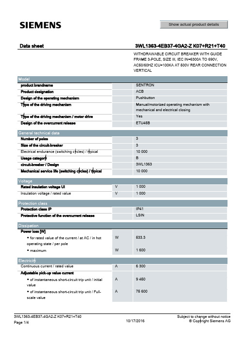
°C
● during storage / maximum
°C
Certificates Equipment marking ● acc. to DIN EN 61346-2 ● acc. to DIN EN 81346-2
85
100 100 85 50
220 220 187 105
Main terminal on the rear vertical
Suitability Suitability for use
Product details Product component ● Trip indicator ● Voltage trigger ● undervoltage release Product extension / optional / motor drive
busbar connection
466.5 704 485.5 drawer unit
-20 55 -40 70
Q Q
3WL1363-4EB37-4GA2-Z K07+R21+T40 Page 3/4
10/17/2016
Subject to change without notice © Copyright Siemens AG
● 1 / rated value
Hz
● 2 / rated value
Hz
Operating voltage
APTGT100H60TG资料
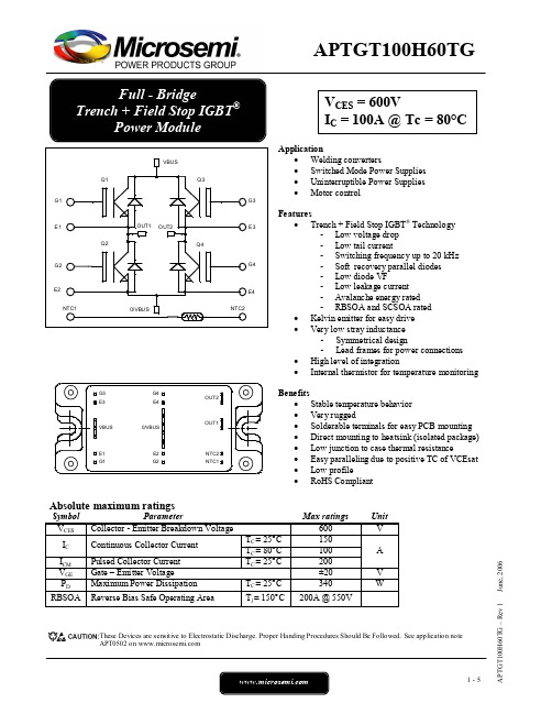
Reverse Bias Safe Operating Area 250
3-5
APTGT100H60TG – Rev 1
June, 2006
元器件交易网
APTGT100H60TG
Typical Performance Curve
Output Characteristics (V GE=15V) Output Characteristics 200 175 150 IC (A)
APTGT100H60TG
All ratings @ Tj = 25°C unless otherwise specified Electrical Characteristics
Symbol Characteristic ICES VCE(sat) VGE(th) IGES Zero Gate Voltage Collector Current Collector Emitter Saturation Voltage Gate Threshold Voltage Gate – Emitter Leakage Current Test Conditions VGE = 0V, VCE = 600V Tj = 25°C VGE =15V IC = 100A Tj = 150°C VGE = VCE , IC = 1.5 mA VGE = 20V, VCE = 0V Min Typ 1.5 1.7 5.8 Max 250 1.9 6.5 400 Unit µA V V nA
Parameter Collector - Emitter Breakdown Voltage Continuous Collector Current Pulsed Collector Current Gate – Emitter Voltage Maximum Power Dissipation TC = 25°C TC = 80°C TC = 25°C TC = 25°C Tj = 150°C
艾顿PDG34P0600E3ZK电源防御型电源说明说明书
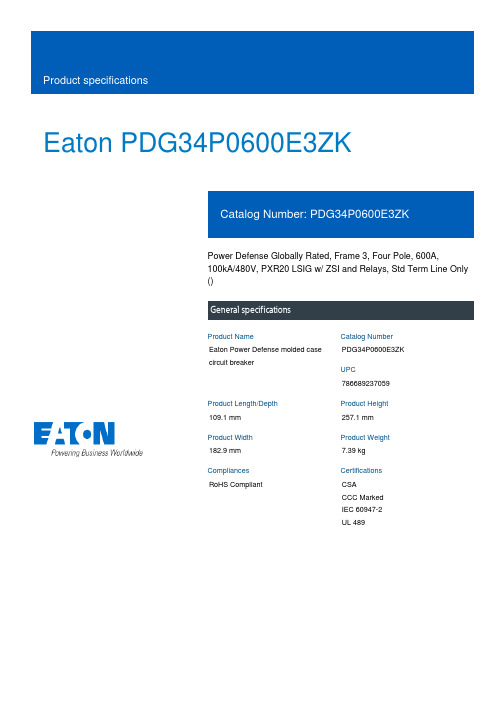
Eaton PDG34P0600E3ZKPower Defense Globally Rated, Frame 3, Four Pole, 600A,100kA/480V, PXR20 LSIG w/ ZSI and Relays, Std Term Line Only ()Eaton Power Defense molded case circuit breakerPDG34P0600E3ZK 786689237059109.1 mm 257.1 mm 182.9 mm 7.39 kg RoHS CompliantCSA CCC Marked IEC 60947-2 UL 489Product NameCatalog Number UPCProduct Length/Depth Product Height Product Width Product Weight Compliances Certifications600 AComplete breaker 3Four-pole PD3 Global Class A600 Vac 600 V100% neutral protection Standard Terminals Line only100 kAIC at 480 Vac100 kAIC @480/277V (UL)200 kAIC Icu/ 150 kAIC Ics/ 440 kAIC Icm @240V (IEC)35 kAIC Icu/ 18 kAIC Ics/ 73.5 kAIC Icm @690V (IEC)200 kAIC @240V (UL)85 kAIC Icu/ 40 kAIC Ics/ 187 kAIC Icm @480V Brazil (IEC)40 kAIC Icu/ 25 kAIC Ics/ 84 kAIC Icm @525V South Africa (IEC)100 kAIC Icu/ 50 kAIC Ics/ 220 kAIC Icm @380-415V (IEC)65 kAIC @600/347V (UL)100 kAIC Icu/ 50 kAIC Ics/ 220 kAIC Icm @440V (IEC)Consulting application guide - molded case circuit breakersStrandAble terminals product aidPower Defense technical selling bookletPower Defense brochurePower Defense molded case circuit breaker selection posterPower Xpert Release trip units for Power Defense molded case circuit breakersMolded case circuit breakers catalogPDG3 CSA certification 100-400aPDG3 UL authorization 250-600a TMTUPDG3 45-400A CB reportPDG3B 450A-600A CB reportPDG3 CSA certification 250-600aPDG3 UL authorization 100-400aAmperage RatingCircuit breaker frame type FrameNumber of poles Circuit breaker type ClassVoltage rating Voltage rating - maxProtection TerminalsInterrupt rating Interrupt rating range Application notes BrochuresCatalogs Certification reportsEU Declaration of Conformity - Power Defense molded case circuit breakersInstallation instructionsPower Defense Frame 3 interphase barrier - IL012229EN H03Power Defense Frame 1-2-3-4 IP door barrier assembly instructions -IL012278ENPower Defense Frame 3 trip unit replacement instructions - IL012157EN Power Defense Frame 3 screw terminal_end cap kit, 400A, 4 pole –IL012263ENPower Defense Frame 3 multi wire connector kit -PDG3X3(2)(4)TA4006W and PDG3X3(2)(4)TA4003W instructions-IL012247EN H01Power Defense Frame 4 reverse feed connector kit instructions for PDG4X3(2)(4)TA800RF instructions - IL012254ENPower Defense Frame 3 interphase barriers 3-pole - IL012229EN H01 Power Defense Frame 3 shunt trip UVR instructions - IL012140EN Power Defense Frame 3 reverse feed connector kit Cat NumPDG3X3(2)(4)TA400HRF instructions - IL012252ENPower Defense Frame 3 screw terminal end cap kit 600A, 4 pole -IL012265ENPower Defense Frame 3 multi-tap terminal kit Cat NumPDG3X3(2)(4)TA6006WSW instructions - IL012250ENPower Defense Frame 3 reverse feed connector kit Cat NumPDG3X3(2)(4)TA630RF instructions - IL012253ENPower Defense Frame 3 box terminal installation instructions -IL012299ENPower Defense Frame 3 extendable shaft rotary handle mech -IL012112ENPower Defense Frame 3 adapter kit installation instructions LZM3 to PD3 - IL012227ENPower Defense Frame 3 handle mech direct rotary handle instructions - IL012111ENPower Defense Frame 3 locking devices and handle block instructions - IL012150ENPower Defense Frame 2/3/4/5/6 voltage neutral sensor module wiring instructions – IL012316ENPower Defense Frame 3 Breaker Instructions (IL012107EN).pdfPower Defense Frame 3 terminal spreader assembly instructions -IL012301ENPower Defense Frame 3 terminal kit Cat Num PDG3X3(2)(4)TA400RF instructions - IL012251ENPower Defense Frame 3 finger protection assembly installation instructions - IL012279ENPower Defense Frame 3 rear connection installation instructions -IL012300ENPower Defense Frame 3 plug-in adapter installation instructions -IL012311ENPower Defense Frame 4 locking devices and handle block instructions - IL012151ENPower Defense Frame 3 Direct Rotary Handle Assy With Interlock Version Instructions (IL012139EN).pdfPower Defense Frame 3 Aux, Alarm, ST and UVR Animated Instructions.rh Power Defense Frame 4 shunt trip UVR instructions - IL012129EN Power Defense Frame 3 terminal cover assembly instructions -IL012281ENPower Defense Frame 3 multi-tap terminal kit Cat NumPDG3X3(2)(4)TA6006W Instructions - IL012248ENInstallation videosPower Defense Frame 3 Shunt Trip_UVR Animated Instructions.pdf.rh Power Defense Frame 3 Handle Mech Direct Rotary Handle Animated Instructions.rhPower Defense Frame 3 Locking Devices and Handle Block Animated Instructions.pdf.rhPower Defense Frame 3 trip unit replacement animated instructions.rh MultimediaPower Defense Frame 3 Variable Depth Rotary Handle Mechanism Installation How-To VideoPower Defense Frame 6 Trip Unit How-To VideoEaton Power Defense for superior arc flash safetyPower Defense BreakersPower Defense Frame 5 Trip Unit How-To VideoPower Defense Frame 2 Variable Depth Rotary Handle Mechanism Installation How-To VideoPower Defense molded case circuit breakersSpecifications and datasheetsEaton Specification Sheet - PDG34P0600E3ZKTime/current curvesPower Defense time current curve Frame 3 - PD3Warranty guidesSelling Policy 25-000 - Distribution and Control Products and Services White papersMolded case and low-voltage power circuit breaker healthSafer by design: arc energy reduction techniquesEaton Corporation plc Eaton House30 Pembroke Road Dublin 4, Ireland © 2023 Eaton. All Rights Reserved. Eaton is a registered trademark.All other trademarks areproperty of their respectiveowners./socialmediaMaking a better machineIntelligent power starts with accurate, actionable dataImplementation of arc flash mitigating solutions at industrial manufacturing facilitiesSingle and double break MCCB performance revisitedIntelligent circuit protection yields space savings。
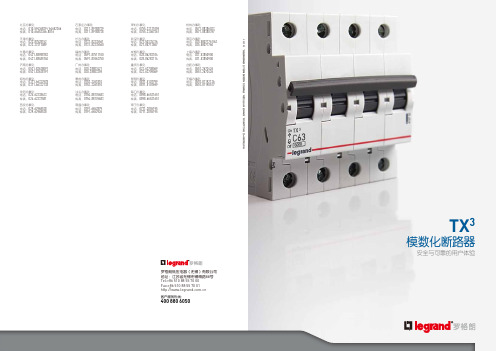
罗格朗TX3手册
11 12
住宅领域和商业建筑(酒 店,城市综合体等)的最佳 解决方案。
安全与可靠的用户体验
安全 可靠 便捷
快捷简单的接线方式: ● IP2X防护等级 ● 强大的接线能力35mm2 ● 牢固可靠的接线端子 ● 可与一字螺丝刀配合使用
简单可视的标识 ● 无需现场拼装 ● 精简的产品型号和库存管理 双卡件结构安装更牢靠 在导轨上易于摆放和移除
10
为什么需要能源测量?
测量是所有数据分析的基础。通过测量电能使用 情况,并以此为基础寻找节能空间并采取相应措 施,可帮助节能8-12%、优化电能使用并实现 可持续发展。商业楼宇需要节能,这就要求根据 负载类型,对每一用户单元的的能耗(如暖气、 制冷、热水系统、照明、电源插座)进行测量, 并以尽可能贴近用户的方式加以显示。
1413安全可靠便捷安全与可靠的用户体验rohsreach1516技术参数产品名称符合标准产品认证电气特性额定电流a额定绝缘电压v最大工作电压v最小工作电压v额定工作频率hz额定冲击耐受电压kv过电压类别污染等级瞬时脱扣特性漏电附件电器附件及机械辅件电击防护等级机械特性机械寿命电气寿命防护等级断路器本体安装于配电箱内基准整定温度其他特性端子形式最大接线能力25a25a25a端子极限扭矩25a进线方式额定极限短路分断能力icu230v400viecen609472额定短路能力icn230v400viecen60989额定运行短路分断能力ics230v400viecen609472产品号规则剩余动作电流01a02a03a04a06a10a16a20a25a32a40a50a63a1p1pn2p3pn3p4p系列代码额定电流a分类编码ou相线中性线过欠压整体式分断能力曲线tx3030e拼装式辅件模数化断路器剩余动作断路器tx3tx3r030e30ma电子式整体式拼装式辅件编码casdcasdcasdcaetstopgomtpopcm辅助触点信号触点辅助信号转换触点辅助信号组合触点分励脱扣单元自动重合控制辅件延时欠压脱扣单元过压脱扣单元远程控制辅件指示断路器分合闸状态同时当断路器状态发生改变时提供远程信号
艾特顿278446Moeller系列ZB过压保护器ZB32说明书
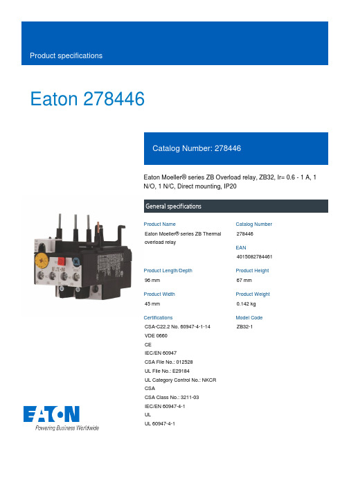
Eaton 278446Eaton Moeller® series ZB Overload relay, ZB32, Ir= 0.6 - 1 A, 1N/O, 1 N/C, Direct mounting, IP20General specificationsEaton Moeller® series ZB Thermaloverload relay278446401508278446196 mm67 mm45 mm0.142 kgCSA-C22.2 No. 60947-4-1-14 VDE 0660CEIEC/EN 60947CSA File No.: 012528UL File No.: E29184UL Category Control No.: NKCR CSACSA Class No.: 3211-03IEC/EN 60947-4-1ULUL 60947-4-1ZB32-1Product Name Catalog NumberEANProduct Length/Depth Product Height Product Width Product Weight Certifications Model CodeReset pushbutton manual/auto Test/off buttonPhase-failure sensitivity (according to IEC/EN 60947, VDE 0660 Part 102) Trip-free release-25 °C55 °C25 °C40 °C CLASS 10 A Damp heat, cyclic, to IEC 60068-2-30 Damp heat, constant, to IEC 60068-2-78IP20ZB32Direct mounting Direct attachment0.6 A1 AIII3Finger and back-of-hand proof, Protection against direct contact when actuated from front (EN 50274)FeaturesAmbient operating temperature - min Ambient operating temperature - max Ambient operating temperature (enclosed) - min Ambient operating temperature (enclosed) - max Class Climatic proofingDegree of protection Frame size Mounting method Overload release current setting - min Overload release current setting - max Overvoltage category Pollution degree Product category ProtectionAccessoriesOverload relay ZB up to 150 A6000 V AC4000 V (auxiliary and control circuits)10 g, Mechanical, Sinusoidal, Shock duration 10 ms Branch circuits, (UL/CSA)≤ 0.25 %/K, residual error for T > 40° Continuous 1 x (0.75 - 2.5) mm², Control circuit cables1 x (1 - 4) mm², Main cables2 x (1 - 4) mm², Main cables2 x (0.75 - 2.5) mm², Control circuit cables2 x (0.75 - 4) mm², Control circuit cables2 x (1 - 6) mm², Main cables1 x (0.75 - 4) mm², Control circuit cables1 x (1 - 6) mm², Main cables18 - 8, Main cables2 x (18 - 14), Control circuit cables10 mm8 mmM4, Terminal screwM3.5, Terminal screw, Control circuit cables1 x 6 mm, Terminal screw, Standard screwdriver 2, Terminal screw, Pozidriv screwdriver1.2 Nm, Screw terminals, Control circuit cables 1.8 Nm, Screw terminals, Main cables6 A 1.5 A 1.5 A 0.9 A 1 A, Class J/CC, max. Fuse, SCCR (UL/CSA)100 kA, Fuse, SCCR (UL/CSA)25 A gG/gL, Fuse, Type “1” coordinationMax. 6 A gG/gL, fuse, Without welding, Auxiliary and control circuits4 A gG/gL, Fuse, Type “2” coordinationRated impulse withstand voltage (Uimp)Shock resistanceSuitable forTemperature compensation Terminal capacity (flexible with ferrule) Terminal capacity (solid)Terminal capacity (solid/stranded AWG) Stripping length (main cable)Stripping length (control circuit cable) Screw sizeScrewdriver sizeTightening torqueConventional thermal current ith of auxiliary contacts (1-pole, open)Rated operational current (Ie) at AC-15, 120 VRated operational current (Ie) at AC-15, 220 V, 230 V, 240 V Rated operational current (Ie) at AC-15, 380 V, 400 V, 415 V Short-circuit current rating (high fault at 600 V) Short-circuit protection rating0.4 A0.2 A0.9 A0.75 A690 V440 V, Between auxiliary contacts and main contacts, According to EN 61140240 V AC, Between auxiliary contacts, According to EN 61140 440 V AC, Between main circuits, According to EN 61140B600 at opposite polarity, AC operated (UL/CSA)R300, DC operated (UL/CSA)B300 at opposite polarity, AC operated (UL/CSA)600 VAC600 VAC 011116.9 W0 W2.3 W1 A0 WMeets the product standard's requirements. Meets the product standard's requirements. Meets the product standard's requirements. Meets the product standard's requirements. Meets the product standard's requirements.Rated operational current (Ie) at DC-13, 110 VRated operational current (Ie) at DC-13, 220 V, 230 V Rated operational current (Ie) at DC-13, 24 VRated operational current (Ie) at DC-13, 60 VRated operational voltage (Ue) - maxSafe isolationSwitching capacity (auxiliary contacts, pilot duty) Voltage rating - maxVoltage rating - max Number of auxiliary contacts (change-over contacts)Number of auxiliary contacts (normally closed contacts) Number of auxiliary contacts (normally open contacts) Number of contacts (normally closed contacts)Number of contacts (normally open contacts)Equipment heat dissipation, current-dependent PvidHeat dissipation capacity PdissHeat dissipation per pole, current-dependent PvidRated operational current for specified heat dissipation (In) Static heat dissipation, non-current-dependent Pvs10.2.2 Corrosion resistance10.2.3.1 Verification of thermal stability of enclosures10.2.3.2 Verification of resistance of insulating materials to normal heat10.2.3.3 Resist. of insul. mat. to abnormal heat/fire by internal elect. effects10.2.4 Resistance to ultra-violet (UV) radiation10.2.5 LiftingDoes not apply, since the entire switchgear needs to be evaluated.Does not apply, since the entire switchgear needs to be evaluated.Meets the product standard's requirements.Does not apply, since the entire switchgear needs to be evaluated.Meets the product standard's requirements.Does not apply, since the entire switchgear needs to be evaluated.Does not apply, since the entire switchgear needs to be evaluated.Is the panel builder's responsibility.Is the panel builder's responsibility.Is the panel builder's responsibility.Is the panel builder's responsibility.Is the panel builder's responsibility.The panel builder is responsible for the temperature rise calculation. Eaton will provide heat dissipation data for the devices.Is the panel builder's responsibility. The specifications for the switchgear must be observed.Is the panel builder's responsibility. The specifications for the switchgear must be observed.Product Range Catalog Switching and protecting motorseaton-tripping-zb-overload-relay-characteristic-curve-002.epseaton-tripping-devices-zb-overload-relay-characteristic-curve-006.epsDA-DC-00004843.pdfDA-DC-00004853.pdfeaton-tripping-devices-zb-overload-relay-dimensions-002.epseaton-tripping-devices-overload-relay-zb-overload-relay-dimensions.eps eaton-tripping-devices-overload-relay-zb-overload-relay-dimensions-004.epseaton-tripping-devices-overload-relay-zb-overload-relay-3d-drawing-002.epsETN.ZB32-1IL03407015ZIL03407195Zeaton-motor-protective-relay-zb12-zb32-overload-monitoring-exe-manual-mn03407004z-de-de-en-us.pdfDA-CD-zb32DA-CS-zb32eaton-tripping-devices-overload-relay-zb-overload-relay-wiring-diagram-003.eps10.2.6 Mechanical impact10.2.7 Inscriptions10.3 Degree of protection of assemblies10.4 Clearances and creepage distances10.5 Protection against electric shock10.6 Incorporation of switching devices and components 10.7 Internal electrical circuits and connections10.8 Connections for external conductors10.9.2 Power-frequency electric strength10.9.3 Impulse withstand voltage10.9.4 Testing of enclosures made of insulating material 10.10 Temperature rise10.11 Short-circuit rating10.12 Electromagnetic compatibility10.13 Mechanical function Catalogues Characteristic curve Declarations of conformity DrawingseCAD modelInstallation instructions Manuals and user guides mCAD modelWiring diagramsEaton Corporation plc Eaton House30 Pembroke Road Dublin 4, Ireland © 2023 Eaton. All rights reserved. Eaton is a registered trademark.All other trademarks areproperty of their respectiveowners./socialmediaThe device meets the requirements, provided the information in the instruction leaflet (IL) is observed.。
- 1、下载文档前请自行甄别文档内容的完整性,平台不提供额外的编辑、内容补充、找答案等附加服务。
- 2、"仅部分预览"的文档,不可在线预览部分如存在完整性等问题,可反馈申请退款(可完整预览的文档不适用该条件!)。
- 3、如文档侵犯您的权益,请联系客服反馈,我们会尽快为您处理(人工客服工作时间:9:00-18:30)。
APTGT20H60T3G
Full - Bridge Trench + Field Stop IGBT® Power Module
13 14
VCES = 600V IC = 20A @ Tc = 80°C
Application • Welding converters • Switched Mode Power Supplies • Uninterruptible Power Supplies • Motor control Features • Trench + Field Stop IGBT® Technology - Low voltage drop - Low tail current - Switching frequency up to 20 kHz - Soft recovery parallel diodes - Low diode VF - Low leakage current - Avalanche energy rated - RBSOA and SCSOA rated • Kelvin emitter for easy drive • Very low stray inductance - Symmetrical design • High level of integration • Internal thermistor for temperature monitoring Benefits • Stable temperature behavior • Very rugged • Solderable terminals for easy PCB mounting • Direct mounting to heatsink (isolated package) • Low junction to case thermal resistance • Easy paralleling due to positive TC of VCEsat • Low profile • Each leg can be easily paralleled to achieve a phase leg of twice the current capability • RoHS Compliant Max ratings 600 32 20 40 ±20 62 40A @ 550V Unit V
TJ=150°C TJ = 150°C VGE=19V
40 35 30
IC (A)
TJ=25°C TJ =125°C
25 20 15 10 5 0 0 0.5 1
T J=25°C
25 20 15 10 5 0
VGE=13V VGE=15V
V GE=9V
1.5 VCE (V)
2
2.5
3
0
0.5
1
1.5 2 VCE (V)
Maximum Peak Repetitive Reverse Voltage
Test Conditions Tj = 25°C Tj = 150°C Tc = 80°C Tj = 25°C Tj = 150°C Tj = 25°C Tj = 150°C Tj = 25°C Tj = 150°C Tj = 25°C Tj = 150°C
A V W
Pulsed Collector Current Gate – Emitter Voltage Maximum Power Dissipation Reverse Bias Safe Operating Area
These Devices are sensitive to Electrostatic Discharge. Proper Handing Procedures Should Be Followed. See application note APT0502 on
2.5
3
3.5
40 35 30
Transfert Characteristics 1.25
T J=25°C
Energy losses vs Collector Current
VCE = 300V VGE = 15V RG = 12Ω TJ = 150°C
1 E (mJ) 0.75 0.5 0.25
Eoff Er
25 IC (A) 20 15 10 5 0 5 6 7 8
T J=125°C T J=150°C TJ=25°C
Eon
பைடு நூலகம்
0 11 12 0 10 20 IC (A) Reverse Bias Safe Operating Area 50
5.0
Dynamic Characteristics
Symbol Characteristic Cies Coes Cres Td(on) Tr Td(off) Tf Td(on) Tr Td(off) Tf Eon Eoff Input Capacitance Output Capacitance Reverse Transfer Capacitance Turn-on Delay Time Rise Time Turn-off Delay Time Fall Time Turn-on Delay Time Rise Time Turn-off Delay Time Fall Time Turn-on Switching Energy Turn-off Switching Energy
3-5
APTGT20H60T3G – Rev 1,
June, 2006
17
28
元器件交易网
APTGT20H60T3G
Typical Performance Curve
Output Characteristics (VGE=15V) Output Characteristics 40 35 30 IC (A)
元器件交易网
APTGT20H60T3G
All ratings @ Tj = 25°C unless otherwise specified Electrical Characteristics
Symbol Characteristic ICES VCE(sat) VGE(th) IGES Zero Gate Voltage Collector Current Collector Emitter Saturation Voltage Gate Threshold Voltage Gate – Emitter Leakage Current Test Conditions VGE = 0V, VCE = 600V Tj = 25°C VGE =15V IC = 20A Tj = 150°C VGE = VCE , IC = 300µA VGE = 20V, VCE = 0V Min Typ 1.5 1.7 5.8 Max 250 1.9 6.5 300 Unit µA V V nA
元器件交易网
APTGT20H60T3G
Temperature sensor NTC (see application note APT0406 on for more information).
Symbol Characteristic R25 Resistance @ 25°C B 25/85 T25 = 298.15 K Min Typ 50 3952 Max Unit kΩ K
Min
Typ 1100 70 35 110 45 200 40 120 50 250 60 0.11 0.2 0.5 0.7
Max
Unit pF
ns
ns
mJ mJ
Reverse diode ratings and characteristics
Symbol Characteristic VRRM IRM IF VF trr Qrr Er
Min 600
Typ
Max 100 350
Unit V µA A
Maximum Reverse Leakage Current DC Forward Current Diode Forward Voltage Reverse Recovery Time Reverse Recovery Charge Reverse Recovery Energy
Test Conditions VGE = 0V VCE = 25V f = 1MHz Inductive Switching (25°C) VGE = ±15V VBus = 300V IC = 20A R G = 12Ω Inductive Switching (150°C) VGE = ±15V VBus = 300V IC = 20A R G = 12Ω Tj = 25°C VGE = ±15V VBus = 300V Tj = 150°C IC = 20A Tj = 25°C R G = 12Ω Tj = 150°C
14 13
All multiple inputs and outputs must be shorted together Example: 13/14 ; 29/30 ; 22/23 …
Absolute maximum ratings
Symbol VCES IC ICM VGE PD RBSOA
Parameter Collector - Emitter Breakdown Voltage Continuous Collector Current TC = 25°C TC = 80°C TC = 25°C TC = 25°C TJ = 150°C
RT =
R 25
1 1 RT : Thermistor value at T exp B 25 / 85 T − T 25
T: Thermistor temperature
Thermal and package characteristics
