必联BL-P8168 PCI-E全千兆自适应以太网网卡
解决RTL8168EPCI-E或...
解决RTL8168E PCI-E或者Realtek RTL81688111(PHY Realtek RTL82118212) 的网卡安装两个软件的检测不大一致,无论使用1000还是81xx都无法驱动,甚至无法使用官网的RTG2.0.6安装,使用提示是安装程序出错。
困扰了很久了。
不负责任的猜测,是因为dsdt里没有关于这个网卡的描述,所以驱动无法安装。
思路:在以前威廉第三的关于dsdt帖子中曾经提到可以通过IORegistryExplorer看到网卡所在的pex位置,而同一个帖子里提供的patcher可以在网卡的位置上添加一段关于网卡的信息代码,将这段代码复制到dsdt相应位置应该就可以解决这个问题。
解决:在lion中使用io可以看到网卡位置在pex 05通过patcher得到以下代码:Device (GIGE){Name (_ADR, Zero)Name (_PRW, Package (0x02) {0x09,0x03})Method (EWOL, 1, NotSerialized) {If (LEqual (Arg0, One)){Or (GP9, One, GP9) }Else{And (GP9, Zero, GP9) }If (LEqual (Arg0, GP9)) {Return (Zero) }Else{Return (One) }}}将其拷贝到pex5的代码下,最终形成Device (PEX5){Name (_ADR, 0x001C0005) Method (_STA, 0, NotSerialized) {Return (0x0F)}Method (_PRW, 0, NotSerialized) {Return (Package (0x02) {0x09,0x05})}Name (PIC5, Package (0x04) {Package (0x04){0xFFFF,Zero,LNKB,Zero},Package (0x04) {0xFFFF, One,LNKC, Zero},Package (0x04) {0xFFFF, 0x02,LNKD, Zero},Package (0x04) {0xFFFF, 0x03,LNKA, Zero}})Name (API5, Package (0x04) { Package (0x04) {0xFFFF, Zero, Zero,0x11},Package (0x04) {0xFFFF, One,Zero,0x12},Package (0x04) {0xFFFF,0x02,Zero,0x13},Package (0x04){0xFFFF,0x03,Zero,0x10}})Method (_PRT, 0, NotSerialized) { If (LNot (PICF)){Return (PIC5)}Else{Return (API5)}}Device (GIGE){Name (_ADR, Zero)Name (_PRW, Package (0x02) {0x09,0x03})Method (EWOL, 1, NotSerialized) {If (LEqual (Arg0, One)) {Or (GP9, One, GP9) }Else{And (GP9, Zero, GP9) }If (LEqual (Arg0, GP9)) {Return (Zero)}Else{Return (One)}}}}编译成dsdt,替换后进入系统,安装RTG2.0.6,重新启动,好吧,这个世界清静了。
电脑配置

处理器
英特尔 Pentium(奔腾) G2020 @ 2.90GHz 英特尔 Pentium(奔腾) D 2.80GHz 英特尔 Celeron(赛扬) 420 @ 1.60GHz 英特尔 Pentium(奔腾) 4 3.06GHz 英特尔 Pentium(奔腾) G2020 @ 2.90GHz 英特尔 Pentium(奔腾) 双核 E5300 @ 2.60GHz 英特尔 Pentium(奔腾) 双核 E5400 @ 2.70GHz 英特尔 Celeron(赛扬) E3500 @ 2.70GHz 英特尔 Pentium(奔腾) 4 2.66GHz 英特尔 Pentium(奔腾) D 3.00GHz 英特尔 Celeron(赛扬) 420 @ 1.60GHz 英特尔 Celeron(赛扬) G530 @ 2.40GHz 英特尔 Pentium(奔腾) 双核 E5300 @ 2.60GHz 英特尔 Celeron(赛扬) 430 @ 1.80GHz 英特尔 Pentium(奔腾) 4 2.66GHz 英特尔 Celeron(赛扬) 420 @ 1.60GHz 英特尔 第二代酷睿 i3-2350M @ 2.30GHz 双核 英特尔 Celeron(赛扬) B830 @ 1.80GHz 双核 英特尔 Celeron(赛扬) E3500 @ 2.70GHz 双核 英特尔 第二代酷睿 i3-2350M @ 2.30GHz 双核 英特尔 Celeron(赛扬) E3500 @ 2.70GHz 双核 英特尔 Celeron(赛扬) B830 @ 1.80GHz 双核 英特尔 第二代酷睿 i3-2350M @ 2.30GHz 双核 英特尔 第三代酷睿 i3-3110M @ 2.40GHz 双核 英特尔 Celeron(赛扬) 430 @ 1.80GHz 英特尔 Celeron(赛扬) 420 @ 1.60GHz AMD Sempron(闪龙) LE-1300 英特尔 Pentium(奔腾) 4 2.66GHz 英特尔 Celeron(赛扬) G530 @ 2.40GHz 英特尔 Celeron(赛扬) E3500 @ 2.70GHz 英特尔 Pentium(奔腾) G2020 @ 2.90GHz 英特尔 Pentium(奔腾) 4 2.66GHz 英特尔 Pentium(奔腾) 4 2.66GHz
B-LINK PCI-E 10,100,1000Mbps自适应网卡BL-P8168安装方法和步骤

B-LINK PCI-E 10/100/1000Mbps自适应网卡BL-P8168安装方法和步骤
本网卡完全遵循PCI-E总线主控规范,支持发送/ 接收双通道直接存储器存取,支持半双工/全双工模式和802.3x 流程控制,支持L0s 和L1动态电源管理支持10Mbps、100Mbps、1000Mbps 三种传输速率,自动侦测所连接网络设备的速率、全/半双工模式,具有先进的故障报告功能,主存储器内支持发送/接收描述符的传播和接收,传输数据位矫正无限制,接收数据缓冲区为双字组对齐。
满足最大的可编程读取请求和高级的内部判断控制,可优化总线的利用,使用DMA全局描述符,符合先进先出原则,直接存储器存取可达16位地址,自动适应中断服务计划中断聚结。
本产品完全兼容IEEE 802.3, 802.3u (10BASE-T, 100BASE-TX), 802.3ab (1000BASE-T) 以太网标准,支持半双工/全双
支持自动协商、平行/交叉线自动识别功能,简单易用,且经济实惠,是实现PC接入千兆网络的最佳选择。
BL-P8168安装方法和步骤
第一步,将网卡插入PCI-E槽
第二步,放入驱动光盘
第三步,打开光盘路径,双击“autorun.exe”
第四步,弹出自动安装界面,单击“自动安装”
第五步,选择你所匹配的系统
第六步,单击“下一步”
第七步,单击“安装”
第八步,自动安装驱动程序
第九步,单击“完成”。
Realtek RTL8168 PCI-E Gigabit Ethernet Adapter

RTL8168E集成千兆以太网控制器的PCI Express(W / SPI)概述瑞昱RTL8168E-VB-CG千兆以太网控制器结合三高速IEEE 802.3兼容的媒体存取控制器(MAC),一个三速以太网收发器,PCI Express总线控制器,和嵌入式存储器。
RTL8168E与国家的最先进的DSP技术和混合信号技术,提供高速传输CAT 5类UTP电缆或3类UTP电缆(10Mbps 的)。
如交叉检测和自动校正,极性校正,自适应均衡,串扰消除,回声消除,定时恢复,和纠错功能的实现在高速行驶时提供强大的传输和接收能力。
RTL8168E支持PCI Express 1.1总线接口的主机通信,电源管理,是符合IEEE 802.3u规范的10/100Mbps以太网和千兆以太网的IEEE 802.3ab规格。
它也支持辅助电源自动检测功能,并会自动配置PCI配置空间PCI电源管理寄存器中的相关位。
的的RTL8168E功能的嵌入式一次性可编程(OTP)存储器,更换外部EEPROM(93C46/93C56/93C66)。
RTL8168E支持连接一个64K字节的外部串行外设接口(SPI)闪存。
AT25F512接口允许RTL8168E读取和写入数据,外部SPI闪存设备,并提供64KB的串行编程的快闪记忆体。
高级配置电源管理接口(ACPI)的电源管理作业系统的电源管理(OSPM)的支持,以实现最有效的电源管理能力的现代操作系统是。
PCI MSI(消息信号中断),同时还支持MSI-X。
此外ACPI功能,远程唤醒(包括AMD Magic Packet和微软唤醒帧),支持ACPI和APM(高级电源管理)环境。
为了支持WOL从Deep Power Down状态(例如,D3cold,即主电源关闭,只有辅助的存在),辅助电源必须能够提供所需的功率为RTL8168E。
RTL8168E是完全兼容的:微软NDIS5,NDIS6(IPV4,IPv6,TCP,UDP)的校验和分割任务的卸载(大的发送和巨发送)功能,并支持IEEE 802 IP第2层优先级编码和IEEE 802.1Q 虚拟桥接的地方区域网络(VLAN)。
Transition Networks E-100BTX-FX-06 快联网 Fast Ethern
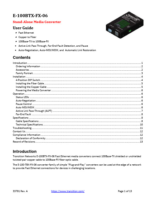
E‐100BTX‐FX‐06Stand‐Alone Media ConverterUser Guide∙Fast Ethernet∙Copper to Fiber∙100Base‐TX to 100Base‐FX∙Active Link Pass Through, Far‐End‐Fault Detection, and Pause∙Auto‐Negotiation, Auto‐MDI/MDIX, and Automatic Link RestorationContentsIntroduction (1)Ordering Information (2)Accessories (2)Family Portrait (3)Installation (4)4‐Position DIP Switch (4)Installing the Fiber Cable (5)Installing the Copper Cable (5)Powering the Media Converter (6)Operation (6)Status LEDs (6)Auto‐Negotiation (6)Pause Control (6)Auto MDI/MDIX (6)Active Link Pass‐Through (ALPT) (7)Far‐End Fault (8)Specifications (8)Cable Specifications (8)Technical Specifications (10)Troubleshooting (11)Contact Us (12)Compliance Information (12)Declaration of Conformity (12)Record of Revisions (13)IntroductionTransition Networks E‐100BTX‐FX‐06 Fast Ethernet media converters connect 100Base‐TX shielded or unshielded twisted‐pair copper cable to 100Base‐FX fiber‐optic cable.The E‐100‐TBX‐FX‐06 converter family of simple “Plug‐and‐Play” converters can be used at the edge of a network to provide Fast Ethernet connections for devices in challenging locations.Ordering InformationPart Number Port One - Copper100Base-TXPort Two - Fiber -100BaseFXE-100BTX-FX-06(SFP) RJ-45100 m (328 ft)*Open SFP Slot (supports 100Mbps SFP modules)E-100BTX-FX-06 RJ-45100 m (328 ft)*ST, 1300 nm multimode2 km (1.2 miles)*E-100BTX-FX-06(SC) RJ-45100 m (328 ft)*SC, 1300 nm multimode2 km (1.2 miles)*E-100BTX-FX-06(LC) RJ-45100 m (328 ft)*LC, 1300 nm multimode2 km (1.2 miles)*E-100BTX-FX-06(SM) RJ-45100 m (328 ft)*SC, 1300 nm multimode20 km (12.4 miles)*E-100BTX-FX-06(SMLC) RJ-45100 m (328 ft)*LC, 1300 nm single mode20 km (12.4 miles)** Typical maximum cable distance. Actual distance depends on the physical characteristics of the network installation. For more information, see https:///.AccessoriesAccessories are sold and packaged separately.Part Number DescriptionSPS‐2460‐SA Optional External Power Supply; 24‐60 VDC and 24‐42 VRMS Stand‐Alone Wide‐Input; Output: 12.25 VDC, 1.0 AE‐MCR‐05 12‐Slot Media Converter Rack (includes universal internal power supply) 17 x 15 x 5 in. (432 x 381 x 127 mm)RMS19‐SA4‐02 4‐Slot Media Converter ShelfWMBL Optional Wall Mount Brackets; 4.0 in. (102 mm)WMBV Optional Vertical Mount Bracket; 5.0 in. (127 mm)WMBD Optional DIN Rail Mount Bracket; 5.0 in. (127 mm)WMBD‐FS Optional DIN Rail Mount Bracket (flat, small); 3.1in. (79 mm) SFPs See the Transition Networks SFP webpage for our full line of SFPs.Family PortraitInstallationCaution: Wear a grounding device and observe electrostatic discharge precautions when setting the4‐position DIP switch and jumpers. Failure to observe this caution could result in failure of the media converter. 4‐Position DIP SwitchThe 4‐position DIP switch is located on the side of the media converter. Use a small flat‐blade screwdriver or a similar tool to set the recessed switches.1. Auto‐NegotiationUp Enables Auto‐Negotiation for the copper connection.Down Disables Auto‐Negotiation for the copper connection.2. Pause ControlUp EnabledDown Disabled3. Active Link Pass‐ThroughUp EnabledDown Disabled4. Far‐End FaultUp EnabledDown DisabledNote: The media converters are shipped from the factory with all DIP switches in the Up (enabled) position.Installing the Fiber Cable1. Locate a 100Base‐FX compliant fiber cable with male, two‐stranded TX to RX connectors installed at both ends.2. Connect the fiber cables to the media converter as described:• Connect the male TX cable connector to the female TX port.• Connect the male RX cable connector to the female RX port.3. Connect the fiber cables to the other device (another media converter, Ethernet Switch, etc.) as described:• Connect the male TX cable connector to the female RX port.• Connect the male RX cable connector to the female TX port.Installing the Copper Cable1. Locate a 100Base‐TX compliant copper cable with male, RJ‐45 connectors installed at both ends.2. Connect the RJ‐45 connector at one end of the cable to the RJ‐45 port on the media converter.3. Connect the RJ‐45 connector at the other end of the cable to the RJ‐45 port on the other device (switch, workstation, etc.).Powering the Media ConverterPower Cord Included: to order the corresponding country‐specific AC power cord, add the Country Code extension to the end of the SKU; NA = North America, LA = Latin America, EU =Europe, UK = United Kingdom,SA = South Africa, JP = Japan, OZ = Australia, BR = Brazil.AC1. Install the power cord barrel connector into the back of the media converter.2. Connect the power adapter plug into AC power.3. Verify that the media converter is powered up by noting that the power LED is lit.DCSee the SPS‐2460‐xx DC External Power Supply User Guide 33455 for more information.OperationStatus LEDsUse the status LEDs to monitor the E‐100BTX‐FX‐06 media converter operation in the network: LED Description MeaningPower Power On = Connected to external AC power.SDF Signal Detect/Fiber On = Fiber link is detected.SDC Signal Detect/Copper On = Copper link is detected.RXC Receive/Copper Flashing = A signal is being received on the copper link.RXF Receive/Fiber Flashing = A signal is being received on the fiber link.Auto‐NegotiationWhen the Auto‐Negotiation feature is activated, the media converter configures itself to achieve the best possible mode of operation over a link, automatically. The media converter broadcasts its speed (100 Mb/s) and duplex capabilities (either fullor half‐duplex) and negotiates the best mode of operation between the two devices. Pause ControlThe Pause feature can improve network performance by allowing one end of the link to signal the other to discontinue frame transmission for a set period of time to relieve buffer congestion.Note: If the Pause feature is available on ALL network devices attached to the media converter(s), enable the Pause feature on the media converter(s); otherwise, disable the Pause feature.Auto MDI/MDIXThe Auto MDI/MDIX feature allows either straight‐through (MDI) or crossover (MDI‐X) cables to be used when connecting to devices such as hubs, transceivers, or network interface cards (NICs). AutoCross determines the characteristics of the cable connection and automatically configures the unit to link up, regardless of the cable configuration.Active Link Pass‐Through (ALPT)Link Pass‐Through is a troubleshooting feature that allows the media converter to monitor both the fiber and copper RX ports for loss of signal. With the loss of RX signal on one media port, the converter will automatically disable the TX signal of the other media port, thus “passing through” the link loss.∙End device automatically notified of link loss∙Prevents loss of valuable data unknowingly transmitted over invalid linkActive LPT is a form of LPT that requires the links to become Active before LPT becomes Active.With Active LPT there are 2 states: Diagnostic and Active.The media converter enters the Diagnostic state when either of the following conditions is met: ∙Upon power‐up of the converter.∙Upon losing Link on either the copper or fiber ports.In the Diagnostic state, the link for each of the media converter’s ports can come up independently of each other, just like a converter that has no LPT functionality, or a converter that has LPT is disabled. The Diagnostic state is helpful during first power up, before all links of a circuit are connected, as it allows the installer to see each link turn on as the cables are plugged in. It’s also helpful for finding the location of a fault, if one exists.The media converter remains in the Diagnostic state until the following condition is met:∙The link status for both of the media converter’s ports is up, simultaneously.After that condition is met, ALPT enters the Active state. It remains in the Active state until the converter is either powered down, or either the copper port or the fiber port loses Link. In the Active state, Active LPT works as shown below (the same as when regular LPT is enabled).Far‐End FaultFar‐End Fault is a valuable feature used in a media converter when it loses Receive Fiber link, but still has a valid Fiber Transmit link.When a fault occurs on an incoming fiber link (1), the media converter transmits a Far‐End Fault signal on the outgoing fiber link (2). In addition, the Far‐End Fault signal also activates the Link Pass‐Through, which in turn disables the link on the copper portion of the network (3) and (4).SpecificationsThe fiber optic cable physical characteristics must meet or exceed IEEE 802.3ae specification.Cable SpecificationsThe physical characteristics must meet or exceed IEEE 802.3™ specifications.Copper CableCategory 5: (minimum requirement)Gauge: 24 to 22 AWGAttenuation: 22.0 db /100m @ 100 MHzMaximum Cable Distance: 100 meters∙Straight-through or crossover cable may be used.∙Shielded twisted-pair (STP) or unshielded twisted-pair (UTP) may be used∙Pins 1&2 and 3&6 are the two active pairs in an Ethernet network∙RJ-45 Pin-out: Pin 1 = TD+, Pin 2 = TD-, Pin 3 = RD+, Pin 6 = RD-∙Use only dedicated wire pairs for the active pins: (e.g., blue/white & white/blue, orange/white & white/orange, etc.)∙Do not use flat or silver satin wire.Fiber CableBit Error Rate: <10‐9Single mode fiber (recommended): 9 μmMultimode fiber (recommended): 62.5/125 μmMultimode fiber (optional): 100/140, 85/140, 50/125 μmE‐100BTX‐FX‐06 1300 nm multimodeFiber Optic Transmitter Power: min: ‐19.0 dBm max: ‐14.0 dBmFiber Optic Receiver Sensitivity: min: ‐30.0 dBm max: ‐14.0 dBmLink Budget: 11.0 dbmE‐100BTX‐FX‐06(SC) & (LC) 1300 nm multimodeFiber Optic Transmitter Power: min: ‐19.0 dBm max: ‐14.0 dBmFiber Optic Receiver Sensitivity: min: ‐30.0 dBm max: ‐14.0 dBmLink Budget: 11.0 dbmE‐100BTX‐FX‐06(SM) 1310 nm single modeFiber‐optic Transmitter Power: min: ‐15.0 dBm max: ‐8.0 dBmFiber‐optic Receiver Sensitivity: min: ‐31.0 dBm max: ‐8.0 dBmLink Budget: 16.0 dbmE‐100BTX‐FX‐06(SMLC) 1310 nm single modeFiber‐optic Transmitter Power: min: ‐15.2 dBm max: ‐8.0 dBmFiber‐optic Receiver Sensitivity: min: ‐32.5 dBm max: ‐3.0 dBmLink Budget: 17.3 dbmThe fiber optic transmitters on this device meet Class I Laser safety requirements per IEC‐825/CDRH standards and comply with 21 CFR1040.10 and 21CFR1040.11.Technical Specifications Standards IEEE 802.3 Data Rate 100 Mb/sDIP Switch SW1: Auto‐Negotiation On/Off SW2: Pause TX On/OffSW3: LPT On/OffSW4: FEF On/OffStatus LEDs PWR (Power): Lit for normal operationSDF (Signal Detect Fiber): Lit for fiber link SDC (Signal Detect Copper): Lit for copper link RXF (Receive Fiber): Flashing = RX dataRXC (Receive Copper): Flashing = RX dataDimensions Width: 3" [76 mm] x Depth: 4.7” [119 mm] x Height: 1" [25 mm]Power Supply External AC/DC required; Output: 12 VDC. 0.41Amps; input 120‐240VAC, unregulated; standardPower Consumption 1.75 Watts (Fixed optics models) 1 Watt plus the SFP (SFP models)Environment Tmra* (Standard temp): 0°C to 50°C (32 to 122°F) Storage Temperature: ‐15°C to 65°C (5 to 149°F) Humidity: 5% to 95% (non‐condensing) Altitude: 0 – 10,000 ft.Weight 6 oz. (181 g) approximatelyCompliance Safety: Wall Mount Power Supply: UL Listed, cUL Listed (Canada). FCC Part 15 Class A, EN 55032:2012, EN 55024:2010Directive 2014/30/EULow‐Voltage Directive 2014/35/EUIEC /EN 60950‐1:2006+A2:20132011/65/EU EN 50581:2012CE MarkMTBF Greater than 46,768 hours (MIL‐HDBK‐217F) Greater than 123,861 hours (Bellcore7 V5.0)Warranty Lifetime* Manufacturer’s rated ambient temperature.CAUTION: Visible and invisible laser radiation when open. Do not stare into beam or view directly with optical instruments.CAUTION: Use of controls, adjustments or the performance of procedures other than those specified herein may result in hazardous radiation exposure.CAUTION: Copper based media ports, e.g., Twisted Pair (TP) Ethernet, USB, RS232, RS422, RS485, DS1, DS3, Video Coax, etc., are intended to be connected to intrabuilding (inside plant) link segments that are not subject to lightening transients or power faults. Copper based media ports, e.g., Twisted Pair (TP) Ethernet, USB, RS232, RS422, RS485, DS1, DS3, Video Coax, etc., are NOT to be connected to inter‐building (outside plant) link segments that are subject to lightening transients or power faults. Failure to observe this caution could result in damage to equipment.TroubleshootingIf the media converter fails, isolate and correct the fault by answering the following questions and then taking the indicated action. Note: DIP switch positions 3 and 4 must be DOWN before starting the troubleshooting process.1. Is the Power LED lit?NO• Is the power adapter the correct model (check I/O voltage and Hz)?• Verify the voltage and frequency of the AC outlet.• Are the power barrel connector and wall plug of the power adapter properly inserted in the media converter and plugged into a live AC wall outlet?• Contact Tech Support. See Contact Us on page 18 below.YES: Proceed to step 2.2. Is the SDC (signal detect/copper) LED lit?NO• Check the twisted‐pair cables for proper connection.• Contact Tech Support. See Contact Us on page 18 below.YES: Proceed to step 3.3. Is the SDF LED (signal detect/fiber) illuminated?NO• Check the fiber cables for proper connection.• Verify that the TX and RX cables on the media converter are connected to the RX and TX ports, respectively, on the other device.• Contact Tech Support. See Contact Us on page 18 below.YES: Proceed to step 4.4. Is the RXC (receive/copper) LED flashing?NO• If there is no activity on the UTP/STP port, proceed to step 5.• If there is activity on the UTP/STP port, disconnect and reconnect the twisted‐pair cable to restart the initialization process.• Contact Tech Support. See Contact Us on page 18 below.YES: Proceed to step 5.5. Is the RXF (receive/fiber) LED flashing?NO• If there is no activity on the fiber port, contact Tech Support.• If there is activity on the fiber port, disconnect / reconnect the fiber cable to restart initialization process.• Contact Tech Support. See Contact Us on page 18 below.YES: Contact Tech Support. See Contact Us on page 18 below.33791 Rev. A / Page 11 of 1333791 Rev. A https:// Page 12 of 13 Contact UsTechnical Support : Technical support is available 24‐hours a dayUS and Canada: 1‐800‐260‐1312International: 00‐1‐952‐941‐7600Main Officetel: +1.952.941.7600 | toll free: 1.800.526.9267 | fax: 952.941.2322******************** | ************************** | ******************************AddressTransition Networks10900 Red Circle DriveMinnetonka, MN 55343, U.S.A.Web : https://Compliance InformationDeclaration of Conformity33791 Rev. A / Page 13 of 13FCC regulationsThis equipment has been tested and found to comply with the limits for a Class A digital device, pursuant to Part 15 of the FCC rules. These limits are designed to provide reasonable protection against harmful interference when the equipment is operated in a commercial environment. This equipment generates, uses and can radiate radio frequency energy and, if not installed and used in accordance with the instruction manual, may cause harmful interference to radio communications.Operation of this equipment in a residential area is likely to cause harmful interference, in which case the user will be required to correct the interference at the user's own expense.Canadian regulationsThis digital apparatus does not exceed the Class A limits for radio noise for digital apparatus set out on the radio interference regulations of the Canadian Department of Communications.Le présent appareil numérique n'émet pas de bruits radioélectriques dépassant les limites applicables aux appareils numériques de la Class A prescrites dans le Règlement sur le brouillage radioélectrique édicté par le ministère des Communications du Canada.European regulationsWarning : This is a Class A product. In a domestic environment this product may cause radio interference in which case the user may be required to take adequate measures.Achtung ! : Dieses ist ein Gerät der Funkstörgrenzwertklasse A. In Wohnbereichen können bei Betrieb dieses Gerätes Rundfunkstörungen auftreten. In diesem Fäll is der Benutzer für Gegenmaßnahmen verantwortlich. Attention ! : Ceci est un produit de Classe A. Dans un environment domestique, ce produit risque de créer des interférences radioélectriques, il appartiendra alors à l'utilsateur de prende les measures spécifiques appropriées.In accordance with European Union Directive 2002/96/EC of the European Parliament and of the Council of 27 January 2003, Transition Networks will accept post usage returns of this product for properdisposal. The contact information for this activity can be found in the 'Contact Us' portion of thisdocument.CAUTION: RJ connectors are NOT INTENDED FOR CONNECTION TO THE PUBLIC TELEPHONE NETWORK. Failure to observe this caution could result in damage to the public telephone network.Der Anschluss dieses Gerätes an ein öffentlickes Telekommunikationsnetz in den EGMitgliedstaaten verstösst gegen die jeweligen einzelstaatlichen Gesetze zur Anwendung der Richtlinie 91/263/EWG zur Angleichung der Rechtsvorschriften der Mitgliedstaaten über Telekommunikationsendeinrichtungen einschliesslich der gegenseitigen Anerkennung ihrer Konformität.Record of RevisionsRevDate NoteA7/25/19 Initial release. Trademark notice : All trademarks and registered trademarks are the property of their respective owners.Copyright restrictions : © 2019 Transition Networks. All rights reserved. No part of this work may be reproduced or used in any form or by any means ‐ graphic, electronic or mechanical ‐ without written permission from Transition Networks.。
PNP系列之网卡篇

心血来潮,讲讲自己的一些经验吧,先把资料整理出来再发。
可能会要点时间,我目前是作VND 相对来说比较了解的无盘就是网众和锐起:主要讲讲这3个的目前工作站用得多的网卡realtek系列 marvell系列及intel 和少量的NF PHY其它的相对来说比较少A REALTEK系列官网realtek系列的网卡分为PCI 及PCIE接口驱动的话分两种一种适用于PCI 一种适用于PCIE的PCI 1000 (以官网数据为准)RTL8110SC(L)RTL8110S-32/RTL8110SB(L)/RTL8169SB(L)/RTL8169SC(L)RTL8169这是芯片的名字,而到了WIN系统的话一般为两类8167和8169如图PCI 100系列(以官网数据为准)RTL8100B(L)/RTL8100C(L)/RTL8101L/RTL8139C(L)RTL8139C(L)+/RTL8139D(L)/RTL8100(L)RTL8130/RTL8139B(L)以上是芯片名字,到了系统的话显示为8139如图PCI -E 1000系列RTL8111B/RTL8168B/RTL8111/RTL8168/RTL8111C这个系列就是一般大家说的8168显示到系统里如图主要是8168B 8168C 8168D区别通过驱动INF文件可以看得出REV 01 对应8168BREV 02 对应8168CREV 03 对应8168D一般情况下按对应的安。
因为虽然驱动文件是一样,但对应的驱动通过对注册表键值对网卡的控制所设计到的键又不一样了这就是为什么最近老有人说锐起在8168C或者什么网卡上(新出的主板)会出现这样那样的问题,锐起所用到的驱动。
相对来说都是比较老的!而锐起PNP模式(穷举VEN DEV而不考虑REV这个版本号)也决定了如果同时存在01 02 03 3种在一个包的话也许我只是说也许会出问题PCI -E 100系列RTL8100E/RTL8101E/RTL8102E-GR也就是平时我们主瓣8136系列这个系列要注意,如图这里是不是有一个显示为8139?其实这不是8139 而是8136(驱动文件INF字段决定它显示的名字)看到了吧:8136同样有3个版本 REV 01 REV 02 REV 03所以不要搞混了关于驱动的选择!PCI系列 :目前最新的版本是 5.699 日期是07/17/2008,5.699.0717.2008 通过WHQL但PCI系列发现高于5.649的驱动,REALTEK PCI网卡在无盘上都会有问题,如断流,启动不了什么的情况,最明显的例子就是网众 5.5的时候吧有几个客户端是用5.671的网卡驱动。
PCI Express x4千兆PoE图像采集卡,PoE网卡

高性能PCI Express x4千兆PoE图像采集卡/PoE网卡产品型号:LREC9714HT-PoE产品名称:PCI Express x4千兆PoE图像采集卡/PoE网卡插口类型:RJ45口/网口产品芯片:英特尔I350AM4传输速率:10/100/1000Mbps传输介质:铜缆适用网络类型:以太网应用领域:机器视觉,视觉检测,工业控制,智能交通.产品概述LREC9714HT-PoE是深圳市联瑞电子有限公司基于Inetl I350AM4芯片方案而自主研发的一款PCI Express x4高性能千兆四口PoE以太网适配卡(以下简称网卡),同时兼容PCIex8、x16通道。
LREC9714HT-PoE提供4个标准PoE供电端口(支持POE功能)。
每个端口可提供15.4W/48V的功率和1000Mb/s的带宽;采用IEEE802.3af and802.3at compliant PoE供电标准;支持9KB巨型帧,支持链路聚合,1000Mb/s的带宽,足以满足各种高清传输要求。
LREC9714HT-PoE在基于英特尔服务器I350AM4四端口以太网MAC+PHY(媒体接入控制器和物理接口收发器)控制器上开发出来的,在千兆位以太网连接中最高时可同时允许四个端口以全双工的工作模式工作以适应高性能网络通信,可以通过链路聚合扩展带宽又可以节约PCI Express通道资源,同时不会占用总线带宽。
同时支持PCI-SIG Single-Root I/O virtualization and sharing specification(SR-IOV)(单根I/O虚拟和共享规范)。
LREC9714HT-PoE该款POE网卡设计主要应用于服务器及高端设备,是市场同类产品中,性能最高的一款产品,其超高的性能和可靠性,可以兼容IEEE802.3af and802.3at标准的各种工业相机和摄像头,广泛应用于机器视觉检测,安防监控、医学成像、智能交通等领域。
HP ProLiant BL p-Class C-GbE2 交换机连接套件快速安装指南说明书
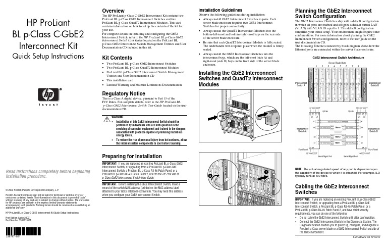
HP ProLiantBL p-Class C-GbE2Interconnect Kit Quick Setup Instructions Read instructions completely before beginninginstallation procedure.© 2003 Hewlett-Packard Development Company, L.P.Hewlett-Packard Company shall not be liable for technical or editorial errors or omissions contained herein. The information in this document is provided “as is” without warranty of any kind and is subject to change without notice. The warranties for HP products are set forth in the express limited warranty statements accompanying such products. Nothing herein should be construed as constituting an additional warranty.HP ProLiant BL p-Class C-GbE2 Interconnect Kit Quick Setup InstructionsFirst Edition (June 2003)Part Number 338797-021338797-021OverviewThe HP ProLiant p-Class C-GbE2 Interconnect Kit contains twoProLiant BL p-Class GbE2 Interconnect Switches and twoProLiant BL p-Class QuadT2 Interconnect Modules. This cardcontains information on how to set up the contents of the kit foryour use.For complete details on installing and configuring the GbE2Interconnect Switch, refer to the HP ProLiant BL p-Class GbE2Interconnect Switch User Guide located on the ProLiant BLp-Class GbE2 Interconnect Switch Management Utilities and UserDocumentation CD included in this kit.Kit Contents• Two ProLiant BL p-Class GbE2 Interconnect Switches• Two ProLiant BL p-Class QuadT2 Interconnect Modules• ProLiant BL p-Class GbE2 Interconnect Switch ManagementUtilities and User Documentation CD• This installation card• Limited Warranty and Material Limitations DocumentationRegulatory NoticeThis is a Class A digital device, pursuant to Part 15 of theFCC Rules. For complete details, refer to the HP ProLiant BLp-Class GbE2 Interconnect Switch User Guide located on the userdocumentation CD.WARNING:• Installation of this GbE2 Interconnect Switch should beperformed by individuals who are both qualified in theservicing of computer equipment and trained in the dangersassociated with products capable of producing hazardousenergy levels.• To reduce the risk of personal injury from hot surfaces, allowthe internal system components to cool before touching.Preparing for InstallationIMPORTANT: If you are replacing an existing ProLiant BL p-Class GbE2Interconnect Switch, or upgrading from a ProLiant BL p-Class GbEInterconnect Switch, a ProLiant BL p-Class RJ-45 Patch Panel, or aProLiant BL p-Class RJ-45 Patch Panel 2, refer to the HP ProLiant BLp-Class GbE2 Interconnect Switch User Guide.IMPORTANT: Before installing the GbE2 Interconnect Switch, make arecord of the switch MAC address (printed on the MAC address labelattached to your GbE2 Interconnect Switch). You may need this addresswhen you configure your GbE2 Interconnect Switch.Installation GuidelinesObserve the following guidelines during installation:• Always install GbE2 Interconnect Switches in pairs. Eachserver blade enclosure requires two GbE2 InterconnectSwitches for proper connectivity.• Always install the QuadT2 Interconnect Modules into thebottom-left-most and bottom-right-most bays on the rear sideof the server blade enclosure.• Be sure that each QuadT2 Interconnect Module is fully seated.The latch/handle will drop into place when the module is firmlyseated.• Always install the GbE2 Interconnect Switches into theinterconnect bays, which are the left-most (side A) andright-most (side B) bays on the front side of the server bladeenclosure.Installing the GbE2 InterconnectSwitches and QuadT2 InterconnectModulesPlanning the GbE2 InterconnectSwitch ConfigurationThe GbE2 Interconnect Switches ship with a default configurationin which all ports are enabled and assigned a default virtual LAN(VLAN) with VLAN ID equal to 1. This default configurationsimplifies your initial setup. Your environment might require otherconfigurations. For more information about planning the GbE2Interconnect Switch configuration, refer to the user guide on theuser documentation CD.The following Ethernet connectivity block diagram shows how theEthernet ports are connected within the server blade enclosure.NOTE: T he actual negotiated speed of any port is dependent uponthe capability of the device to which it is attached. For example, iLOtypically runs at 100 Mb/s.Cabling the GbE2 InterconnectSwitchesIMPORTANT: If you are replacing an existing ProLiant BL p-Class GbE2Interconnect Switch, or upgrading from a ProLiant BL p-Class GbEInterconnect Switch, a ProLiant BL p-Class RJ-45 Patch Panel, or aProLiant BL p-Class RJ-45 Patch Panel 2, and have strict securityrequirements, you can do one of the following:• Do not cable the GbE2 Interconnect Switch until after configuration.• Connect the GbE2 Interconnect Switch to the Diagnostic Station. TheDiagnostic Station enables you to power up, configure, and diagnose aProLiant p-Class server blade or a GbE2 Interconnect Switch outside ofthe rack environment.Continued on reverseConnect the network cables to the QuadT2 InterconnectModules.Item Description 1 Port (22x) RJ-45 connector for 10/100/1000T/TX/T Mb uplink for Switch B2 Port (21x) RJ-45 connector for 10/100/1000T/TX/T Mb uplink for Switch B3 Port (20x) RJ-45 connector for 10/100/1000T/TX/T Mb uplink for Switch B4 Port (19x) RJ-45 connector for 10/100/1000T/TX/T Mb uplink for Switch B5 Port (22x) RJ-45 connector for 10/100/1000T/TX/T Mb uplink for Switch A6 Port (21x) RJ-45 connector for 10/100/1000T/TX/T Mb uplink for Switch A7 Port (20x) RJ-45 connector for 10/100/1000T/TX/T Mb uplink for Switch A8Port (19x) RJ-45 connector for 10/100/1000T/TX/T Mb uplink for Switch APowering Up the GbE2 Interconnect SwitchIf the server blade enclosure has power applied, the GbE2 Interconnect Switch automatically begins to power up when installed. The power status LED on the front of the GbE2 Interconnect Switch will be amber to indicate that power isconnected to the GbE2 Interconnect Switch. After 30 seconds, the power status LED turns to green to indicate that the GbE2 Interconnect Switch is on. After the built-in self-test flashes all LEDs, the active links are illuminated and the power status LED stays green.You can manually force the GbE2 Interconnect Switch to power up by pressing the Pwr/Rst button through the access hole in the front panel of the GbE2 Interconnect Switch, while the power status LED is amber. HP recommends using a small, blunt object for this purpose.CAUTION: Pressing the Pwr/Rst button while the power status LED is green will reset the GbE2 Interconnect Switch.NOTE: If the server blade enclosure does not have power applied, refer to the setup and installation guide for the server blade enclosure .Accessing the GbE2 Interconnect SwitchThe GbE2 Interconnect Switch can be accessed locally using the front panel DB-9 serial management port, or remotely using either the 10/100/1000T/TX/T uplink Ethernet ports in the QuadT2Interconnect Module or the GbE2 Interconnect Switch front panel Ethernet ports.To access the GbE2 Interconnect Switch remotely, you need to assign it an IP address. By default, the GbE2 Interconnect Switch is set up to obtain its IP address from a BOOTP server existing on the attached network.To access the GbE2 Interconnect Switch remotely:1. From the BOOTP server, use the GbE2 Interconnect Switch MAC address to obtain the switch IP address.2. From a computer connected to the same network, use the IP address to access the GbE2 Interconnect Switch using a Web browser or Telnet application. This will allow you to access the GbE2 Interconnect Switch browser-based interface (BBI) or command line interface (CLI). The GbE2 Interconnect Switch logon prompt is displayed.If the GbE2 Interconnect Switch does not obtain the IP address by means of the BOOTP service, you can access the GbE2Interconnect Switch locally and configure the IP address manually. After assigning the IP address to the GbE2 Interconnect Switch, you can then access the switch remotely.To access the GbE2 Interconnect Switch locally:1. Connect the GbE2 Interconnect Switch DB-9 serial connector, using the null-modem serial cable (provided with the following option kits: Scalable Busbar, Mini Busbar, and Power Bus Box), to a local client device (such as a laptop computer) with VT100 terminal emulation software.2. Open a VT100 terminal emulation session with the following settings: 9600 baud rate, eight data bits, no parity, one stop bit, and no flow control.Logging On and Configuring the GbE2 Interconnect SwitchTo log on to the GbE2 Interconnect Switch, use admin for both the default user name and password.NOTE: If you are in the command line interface, you may need to press the ENTER key to display the login prompt.The GbE2 Interconnect Switch comes configured with the factory default configuration. For more information on configuring the GbE2 Interconnect Switch for your network environment, refer to the user guide on the user documentation CD.GbE2 Interconnect Switch Front PanelItem Description Status/Function 1 10G LED Reserved for future use2SAN LEDOff = HP ProLiant BL p-Class GbE2 Storage Connectivity Kit is not installed. On = Refer to the HP ProLiant BL p-Class GbE2 Storage Connectivity Kit Quick Setup Instructions for more information. 3Front panel RJ-45 connector link speed LEDs Amber = 1000 Mb/s Green = 100 Mb/s Off = 10 Mb/s4 Pwr/Rst button Forces the GbE2 Interconnect Switch to power up or reboot5DB-9 connectorUsed to access the local management console6 Front panelRJ-45 connector link activity LEDsGreen = Link and no activityGreen flashing = Link and activity Amber = Port disabled Off = No link7 M anagement status LED Flashing = Management session activeOff = No management session active 8 Power status LED Green = Power on Amber = Stand-by modeOff = Power off 9Link activity and speed LEDsRefer to the following figures and tables for LED assignments and functions.NIC LED FunctionsItem Description Status 1Link speedAmber = 1000 Mb/s Green = 100 Mb/s Off = 10 Mb/s2 Link activityGreen = Link and no activityGreen flashing = Link and activity Amber = Port disabled Off = No linkNIC LED AssignmentsItem Description 1 Server blade slot 1 Ethernet ports 2 Server blade slot 2 Ethernet ports 3 Server blade slot 3 Ethernet ports 4 Server blade slot 4 Ethernet ports 5 Server blade slot 5 Ethernet ports 6 Server blade slot 6 Ethernet ports 7 Server blade slot 7 Ethernet ports 8 Server blade slot 8 Ethernet ports 9 Interswitch cross-connect ports10 Port (19x) RJ-45 connector for rear panel uplink 11 Port (20x) RJ-45 connector for rear panel uplink 12 Port (21x) RJ-45 connector for rear panel uplink 13Port (22x) RJ-45 connector for rear panel uplinkQuadT2 Interconnect Module LEDsItem Description Status1Link activityGreen = Link and no activityGreen flashing = Link and activity Amber = Connector disabled Off = No link 2 Link speedAmber = 1000 Mb/s Green = 100 Mb/s Off = 10 Mb/s。
莫萨 CP-168EL-A 8-口 RS-232 低配置 PCI Express 板的产品介绍和特点
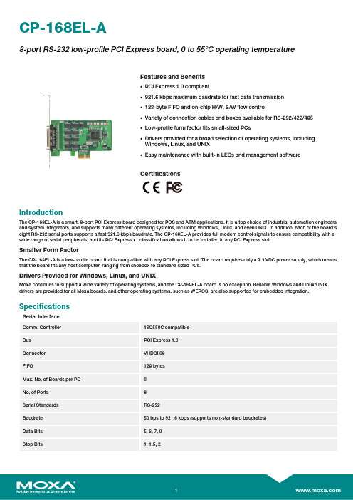
CP-168EL-A8-port RS-232low-profile PCI Express board,0to55°C operating temperatureFeatures and Benefits•PCI Express1.0compliant•921.6kbps maximum baudrate for fast data transmission•128-byte FIFO and on-chip H/W,S/W flow control•Variety of connection cables and boxes available for RS-232/422/485•Low-profile form factor fits small-sized PCs•Drivers provided for a broad selection of operating systems,includingWindows,Linux,and UNIX•Easy maintenance with built-in LEDs and management softwareCertificationsIntroductionThe CP-168EL-A is a smart,8-port PCI Express board designed for POS and ATM applications.It is a top choice of industrial automation engineers and system integrators,and supports many different operating systems,including Windows,Linux,and even UNIX.In addition,each of the board’s eight RS-232serial ports supports a fast921.6kbps baudrate.The CP-168EL-A provides full modem control signals to ensure compatibility with a wide range of serial peripherals,and its PCI Express x1classification allows it to be installed in any PCI Express slot.Smaller Form FactorThe CP-168EL-A is a low-profile board that is compatible with any PCI Express slot.The board requires only a3.3VDC power supply,which means that the board fits any host computer,ranging from shoebox to standard-sized PCs.Drivers Provided for Windows,Linux,and UNIXMoxa continues to support a wide variety of operating systems,and the CP-168EL-A board is no exception.Reliable Windows and Linux/UNIX drivers are provided for all Moxa boards,and other operating systems,such as WEPOS,are also supported for embedded integration.SpecificationsSerial InterfaceComm.Controller16C550C compatibleBus PCI Express1.0Connector VHDCI68FIFO128bytesMax.No.of Boards per PC8No.of Ports8Serial Standards RS-232Baudrate50bps to921.6kbps(supports non-standard baudrates)Data Bits5,6,7,8Stop Bits1,1.5,2Parity None,Even,Odd,Space,MarkFlow Control None,RTS/CTS,XON/XOFFSerial SignalsRS-232TxD,RxD,RTS,CTS,DTR,DSR,DCD,GNDSerial Software FeaturesLinux Drivers Linux kernel2.4.x,Linux kernel2.6.x,Linux kernel3.x,Linux kernel4.x,Linux kernel5.x Windows Drivers DOS,Windows95/98/ME/NT/2000,Windows XP/2003/Vista/2008/7/8/8.1/10(x86/x64),Windows2008R2/2012/2012R2/2016/2019(x64),Windows Embedded CE5.0/6.0,Windows XP EmbeddedUNIX Drivers Solaris10,UnixWare7,SCO OpenServer5,SCO OpenServer6Power ParametersInput Current1,225mA@3.3VDCPhysical CharacteristicsDimensions64.42x102mm(2.54x4.02in)LED InterfaceLED Indicators Built-in Tx,Rx LEDs for each portEnvironmental LimitsOperating Temperature0to55°C(32to131°F)Storage Temperature(package included)-20to85°C(-4to185°F)Ambient Relative Humidity5to95%(non-condensing)Standards and CertificationsEMC EN55032/35EMI CISPR32,FCC Part15B Class BEMS IEC61000-4-2ESD:Contact:4kV;Air:8kVIEC61000-4-3RS:80MHz to1GHz:3V/mIEC61000-4-4EFT:Power:1kV;Signal:0.5kVIEC61000-4-5Surge:Power:2kVIEC61000-4-6CS:150kHz to80MHz:3V/m;Signal:3V/mIEC61000-4-8PFMFDeclarationGreen Product RoHS,CRoHS,WEEEMTBFTime2,351,336hrsStandards Telcordia(Bellcore)Standard TR/SRWarrantyWarranty Period5yearsDetails See /warrantyPackage ContentsDevice1x CP-168EL-A serial boardDocumentation1x quick installation guide1x warranty cardDimensionsOrdering InformationModel Name Serial Standards No.of Serial Ports Form FactorCP-168EL-A w/o Cable RS-2328Low profile Accessories(sold separately)CablesCBL-M68M25x8-100SCSI VHDCI68to8x DB25male serial cable,1mCBL-M68M9x8-100SCSI VHDCI68to8x DB9male serial cable,1mConnection BoxesOPT8-RJ45+VHDCI68to8x RJ45(8-pin)connection boxOPT8-M9+VHDCI68to8x DB9male connection boxOPT8B+VHDCI68to8x DB25male connection boxOPT8S+VHDCI68to8x DB25female connection box with surge protectionOPT8A+VHDCI68to8x DB25female connection box©Moxa Inc.All rights reserved.Updated Oct28,2021.This document and any portion thereof may not be reproduced or used in any manner whatsoever without the express written permission of Moxa Inc.Product specifications subject to change without notice.Visit our website for the most up-to-date product information.。
RTL8168

REALTEKRTL8168INTEGRATED GIGABIT ETHERNET CONTROLLER FOR PCI EXPRESSTM APPLICATIONSDATASHEETRev. 1.1 OS November 2004 Track ID: JATR-I076-21,w REA口EKRealtek Semiconducto r Corp.丁剖:No. 2, Industry E. Rd. IX, Sclence-Based Industrlal Partc. Hslnchu 300, 而iwan +886-3-5780211 Fax: +886-3-5776047 ~ REALTEKRTL8168 DatasheetCOPYRIGHT <<;)2004 Realtek Semiconductor Corp. AIl rights reserved. No part of this document may be reproduced, transmitted , transcribed, stored in a retrieval system , or translated into any language in any fonηor by any means without the written permission ofRealtek Semiconductor Co叩· DI$CLAIMER Realtek provides this document "as i s'飞 without wa汀anty of any kind, neither expressed nor implied, inc1 uding, but not limited to, the particular purpose. Realtek may make improvements and/or changes in this document or in the product described in this document at any time. This document could include technical inaccuracies or typographical errors. TRADEMARK$ Realtek is a trademark of Realtek Semiconductor Corporation. Other names mentioned in this document are trademarks/registered trademarks oftheir respective owners. USING THIS DOCUMENT This document is intended for the software engineer's reference and provides detailed programming information. Though every effort has been made to ensure that this document is current and accurate, more information may have become available subsequent to the producti.on of this guide. In that event, please contact your Realtek representative for additionaJ information that may help in the development process REVISION HISTORYRcvisionRcleasc Datc200-l/08月 l200-l/ 11/05主旦旦旦旦 FirSI rclcasc. Package changes. Sce scclÌon 8, Mechanica1 Dimensions, page 26, and section 9, 0,乱eri ng Jnfonnation, page 27.Integratell Gigahit Ethemet COl1troLler for PCJ Express11..Track lD: JATR-1076-21Rev. 1.1~ REALTEKTable of Contents1. 2.RTL8168 DatasheetGENERAL DESCRIPTION...............................................................................................................1 FEATURES ..........................….................................…..........................……........................…..............2 SYSTEM APPLICATIONS.…tt."..tt………………..ft""……tt tttt tt..".. ,…"…'ft'3.4. 5."..ft..ft" f t' f t t "ft ……,.,......".2PIN ASSIGNMENTS .......................................................................................................................... PIN DESCRIPTIONS ……………………………………………………………………………................................4 5.1 . 5.2. 5.3. 5 .4. 5.5. 5.6. 5.7. 5.8. 5.9. POWER Mi\NAGEMENTlIsOLATION ............ ........................................ .... .... .... .. ....................... .... ....4 PCI EXPRESS II币盯ACE............................. .. ....... . ... . ... . ....... . ... . ...................... . ....... . ... . ... . .............. 4EEPRO岛lIBROM... ….................…..........… .. . ................... .......................................... ....... . . . . . ... . ... 5TRANSCElVER INfE盯ACE... … ………… .. . ................ . ... . ... . ...... ............ ........................ .... ............. . ..... 5CLOCK............ ……… .01..01..01..01. ….00... ,..…………………………………………………………………………… ....6 REFERENCE …-…...........……………..... ....………..........… .............6 LEDs........ ……… .... .... .……….........…·……......................……………………........…….. ....………… 6 POWER & GROUND.... ............... .... ............. .... .... ...….......……......… ……………… 7 NC (NOT Com范CTED) PINs. .................................................................... … ... .. .. ..7REGUL八TOR &6.FUNCTIONAL DESCRIPTION.…….........…..................................…….................…………................8 PCI EXPRESS Bus INTE盯ACE ........ . ............................ …………………·……… .............................. . ..... 8 6.1 . 6.1.1. PCI EYpl白:s Transl11Îlfer .................................................................................................... ...8 6.1.2. prT F.xpress Receit凹·…-一 - 一……· 一…一- …一一- ………-…-…… …-一… · 一… …- &- .. -一 .8 6.2. LED FUNCTIONS ......................................... ........... ..... .. ....... .. .….. ................................................... 8 6.2.1. Link Monifor ..........................................................................................................................8 6.2.2. Rx LED...................................................... .... .........................................................................9 6.2.3. TxLED.…..................................... ........................................................................................10 T XI促x LED...........................................................................................................................11 6.2. -1. 6.2.5. LINK任 CTLED.. ...... .. ..... … ............... .. ........ ... ..... . . ... . ... . ... . . .. .. .. . ... . .. .. ..... ... . ................. . .......ρ 6.3. PHY TR1怡。
Emulex NC552SFP 八路 PCI Express 10 吉比特网络解决方案说明说明书
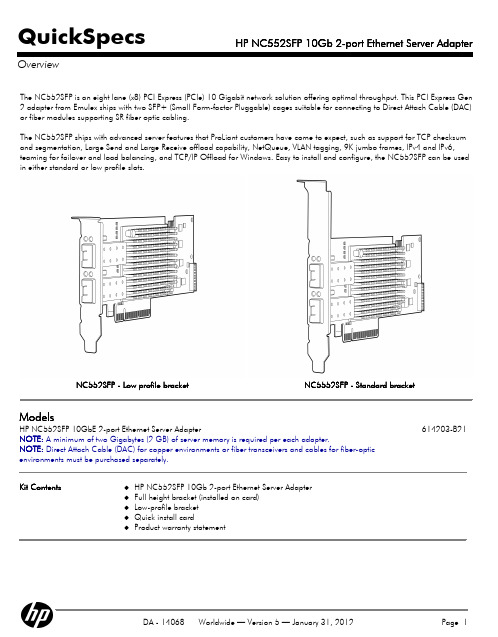
Kit Contents
HP NC552SFP 10Gb 2-port Ethernet Server Adapter Full height bracket (installed on card) Low-profile bracket Quick install card Product warranty statement
Network Management
Management Support
Like all HP ProLiant server adapters, the NC552SFP adapter ships with agents that can be managed from HP Systems Insight Manager or other management application that support SNMP.
HP NC552SFP 10Gb 2-port Ethernet Server Adapter
Performance
Dual-port 10 Gigabit Ethernet Throughput
The 20,000 Mbps full duplex Ethernet transfer rate per port (40 Gbps aggregate full duplex) delivers outstanding network performance that improves response time and removes bottlenecks for the next generation data center. 10 Gigabit Ethernet bandwidth is ideal for high performance computing, database clusters, iSCSI storage, storage backups, grid systems, virtualization, server and I/O consolidation, fabric consolidation, and more.
常见的地集成网络的芯片
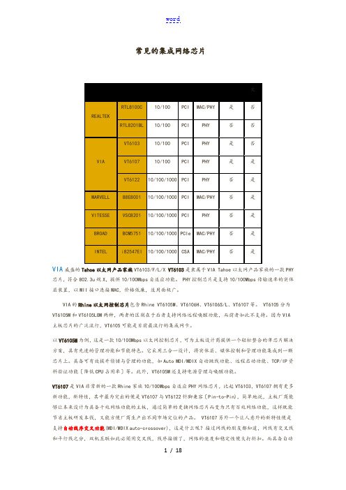
常见的集成网络芯片VIA威盛的Tahoe以太网产品家族VT6103/F/L/X VT6103是隶属于VIA Tahoe以太网产品家族的一款PHY 芯片,符合802.3u规X,提供10/100Mbps自适应功能。
PHY控制芯片是支持10/100Mbps传输速率的实体层装置,以MII接口连接MAC,价格低廉,适用面极广。
VIA的Rhine以太网控制芯片包含Rhine VT6105M、VT6106H、VT6106S/L、VT6107等。
VT6105分为VT6105M和VT6105LOM两种,两者的区别在于后者支持网络远程唤醒功能,而前者如此不支持。
因为VIA 主板芯片的广泛流行,VT6105可能是目前最流行的集成网卡。
以VT6105M为例,这是一款10/100Mbps以太网控制芯片,可为主板设计商提供一个轻松整合的单芯片解决方案,具有先进的管理功能和节能特色。
它采用三合一设计,将实体层、媒体控制和管理功能集成到一颗芯片上。
具备可有效提升侦错与管理的功能,如Auto MDI/MDIX自动跳线功能、远程启动功能、TCP/IP资料验证功能〔降低CPU占用率〕等。
此外,VT6105M还支持电源管理与唤醒功能。
VT6107是VIA非常新的一款Rhine家族10/100Mbps自适应PHY网络芯片,比起VT6103,VT6107拥有更多新功能,新特性,其中最为突出的便是VT6107与VT6122针脚兼容〔Pin-to-Pin),简单地说,主板厂商能够让本来设计为具备千兆网络功能的主板,通过简单的更换网络芯片而变为只有百兆网络功能,这样既能节省主板研发本钱,又能方便厂商生产出不同市场定位的产品。
VT6107另外一个让人意外的新特性便是支持自动线序交叉功能(MDI/MDIX auto-crossover),这是什么呢?接过网线的朋友都知道,网线有交叉线和平行线之分,双机互联如此必须用交叉线,线序接错了,网络的速度和稳定性便大打折扣。
赛诺威盛CT Insitum -32
谨致:XXX医院Insitum 32精广角CT项目建议书SinoVision Technologies赛诺威盛科技( 北京) 有限公司精工细作,广惠众生1、赛诺威盛——横空出世的CT“专+”赛诺威盛科技(北京)有限公司成立于2012年,致力于为医疗机构提供高端医疗影像设备、局域云服务平台、远程协助诊断等一体化的解决方案。
作为国家高新技术企业、中关村高新技术企业,赛诺威盛由多名海内外资深科学家、工程师以及众多国内医疗设备行业精英组成,倾心筑建高端X射线医疗影像设备研发、生产、销售的完整体系。
1 / 25企业的核心发展目标——“自主研发的CT‘专+自主研发:从CT系统的组件设计制造到后期软件处理系统的算法构建,全程自主研发。
“专”:专注于做CT。
2 / 25“+”:在设备上不做“减法”,不为降低成本而牺牲设备性能及用户体验,只做“加法”。
2、我们产品的独特之处:3 / 252.1 “精”—高达20LP/cm精细图像众所周知,孔径越大患者越舒适,越容易满足各种介入、放疗模拟等拓展应用。
然而孔径越大图像的分辨率就越难保证,因而几乎所有厂商都会在影像和扫描孔径之间做出取舍。
赛诺威盛“精广角”系列CT图像质量高达20线对每厘米——这是国际顶级品牌高端设备的影像质量水平,将高分辨图像(20LP/cm)与大孔径机架(76cm)这一对矛盾的特征完美的结合在一起。
型号Insitum32 NeuViz 16 Classic ANATOM 16 uCT 510 MX16 evo2 ACT太行32 Brivo385 Optima 520 Scope power Alexion advance Supria 16 机架孔径cm 76 70 70 70 70 65 65 70 70 72 75 探测器排列方式等宽不等宽不等宽不等宽不等宽不等宽不等宽不等宽不等宽等宽等宽高密度分辨率20lp/cm 15lp/cm 18lp/cm 18lp/cm 15 15.4 15.4 15.4 17.5 18 17之所以能解决大孔径和高清图像这一矛盾,取决于赛诺威盛专利的Vsion影像链:1-专利的vBeam射线管理技术-包含vArc同心圆准直器、vTrack焦点追踪技术、vFliter射线优化技术三大技术。
B-LINK 千兆带管理交换机BL-SG108M

B-LINK 千兆带管理交换机BL-SG108M
目录
简要描述
产品功能
规格参数
图片展示
简要描述
8个10/100/1000Mbps端口
自动MDI/MDIX, 消除对交叉线的需求
端口具有自协商功能, 对10Mbps, 100Mbps及1000Mbps硬件进行智能整合;
无阻断交换结构,使数据得以最大速度进行传输与过滤;
网络管理功能设置简单快捷;
支持基于端口的虚拟局域网, IEEE802.1Q 基于标签的虚拟局域网和基于协议的虚拟局域网; 支持广播风暴控制, 端口安全, 端口镜像, 端口中继, 端口优先级;
支持固件升级,配置备份与恢复;
支持虚拟电缆检测;
产品功能
BL-SG108M是一款带有8个10/100/1000Mbps 端口并具有网络管理功能的交换机结合先进管理功能以及可扩展安全性能,为边缘网络中的高性能工作组、快速以太网主干网的交换机以及小型网络中的高速服务器提供最大传输吞吐量; 而且,QoS增强了线路管理能力, 使数据传输更加顺畅快速。
规格参数
图片展示
开放分类
IT,技术,电子,科技,交换机。
计算机网络基础实验报告

来自127.0.0.1的回复:字节=32时间<1ms TTL=128
127.0.0.1的Ping统计信息:
数据包:已发送= 4,已接收= 4,丢失= 0 (0%丢失),
往返行程的估计时间(以毫秒为单位):
最短= 0ms,最长= 0ms,平均= 0ms
Ping本机IP这个命令被送到你计算机所配置的IP地址,你的计算机始终都应该对该ping命令作出应答,如果没有,则表示本地配置或安装存在问题。
==================================================================
Active Routes:
Network Destination Netmask Gateway Interface Metric
0.0.0.0 0.0.0.0 10.4.24.62 10.4.24.11 20
C:\Documents and Settings\cydn>ipconfig/all
Windows IP Configuration//网络配置窗口
Host Name . . . . . . . . . . . . : 1s11//主机名:1s11
Primary Dns Suffix . . . . . . . ://主DNS后缀
TCP 192.168.242.1:139 jqq315:0 LISTENING
TCP [::]:21 jqq315:0 LISTENING
TCP [::]:80 jqq315:0 LISTENING
4、运行arp命令
无线路由器CPU闪存内存芯片列表

WIFI模块应用领域:串口(RS232/RS485)转WiFi、SPI转WiFi;WiFi远程控制/监控、TCP/IP和Wi-Fi协处理器;WiFi遥控飞机、车等玩具领域;WiFi网络收音机、摄像头、数码相框;医疗仪器、数据采集、手持设备;WiFi脂肪秤、智能卡终端;家居智能化;LED照明灯具电源开关仪器仪表、设备参数监测、无线POS机;现代农业、军事领域等其他无线相关二次开发应用。
汽车电子智能电网工业控制NO 中文名称型号方案 flash (M ) D DR (M ) Data Rate (速率)(M) RF Power壳料材质Power(optional)(电源)1 CPE cpe007 9341 8M/16M 32/64M 300 B:28±2,N :24.5 胶壳 18V/1A2 CPE cpe008 9344 8M/16M 64/128M 300 500MW 胶壳 18V/1A3 CPE cpe012 9331 8M/16M 32/64M 150 500MW 胶壳 18V/1A4 CPEcpe0177240+9285 8M/16M 32/64M150100MW胶壳 18V/1A5 CPE cpe020 7240+92858M/16M 32/64M 150 100MW 胶壳 18V/1A6 CPE cpe021 7240+92838M/16M 32/64M 300 500MW 胶壳 18V/1A7 CPE/壁挂APcpe0217240+92838M/16M 32/64M 300 500MW 铁壳 18V/1A8 CPE/壁挂APAP023 9344 16M 128M 300 500MW 铁壳 18V/1A9 CPE/壁挂APSX-AP-23A AR9344 16M64M/128Mdual-frequency/2.4/5.8B:23±2A:22±2铁壳POE06BorPOE12Aor12V1A10 CPE/壁挂APAR9341 8M/16M 64M 300 500MW 铁壳 24V POEor48V POE11 CPE/壁挂APSX-AP-23A AR9344 16M 128M 600 300 铁壳 24V POEor48V POE12 CPE/壁挂APSX-AP-23A AR9344 16M64M/128Mdual-frequency/2.4/5.8B:23±2A:22±2铁壳POE06BorPOE12Aor12V1A13 入墙AP SX-RQAP-01B AR9331 8M/16M 32/64M 150 100MW 胶壳 POE04BorPOE15Aor14 入墙AP SX--RQAP-05A AR9341 8M/16M 32/64M 300 B:18±1.5 胶壳 POE08A15 入墙AP SX-rqap_07A AR9341 8M 64M 300 300MW 胶壳 POE04BorPOE15A16 室外AP SX-AP-03 AR9344 16M 128M dual-frequency600M/2.4/5.82.4GB:27±1.5A:24/26铁壳 POE06B17 吸顶AP SX-AP-10A6 AR9341 8M/16M 32/64M 300 B:28±2 胶壳POE06BorPOE12Aor12V1 A18 吸顶AP SX-AP-15B AR9344 16M 128M dual-frequency600M/2.4/5.8B:27±2,n:20A:22±2,n:20胶壳POE06BorPOE12Aor12V1A19 吸顶AP SX-AP15 9344+938216M 128M300M/2.4g B:27±2,n:20胶壳POE06BorPOE12Aor12V1A20 吸顶AP SX-AP-16A AR9331 8M/16M 32/64M 150 500MW 胶壳POE06BorPOE12Aor12V1 A21 吸顶AP SX-AP19 8197 8M/16M 32/64M 600M 200MW(23DBM)胶壳 POE06B/POE12Aor12V1.22 吸顶AP SX-AP-20A 8192+81968M/16M 32/64M 300M 500MV 胶壳 POE06B/POE12Aor12V1.23 吸顶AP SX-AP-21A 8197DL 8M/16M 32/64M 600Mbps 200mW 胶壳 POE06B/POE12Aor12V1.24 吸顶AP SX-AP-22A1 AR9341 8M/16M 32/64M 300 B:28±2,N:24.5 胶壳 POE06B/POE12A/(falseP24V1A)25 路由LY-03C 9341 8M/16M 64M 300Mbps 500mW 胶壳POE06BorPOE12Aor12V1 A26 路由LY-06B AR9344 8M/16M 64M/128M300Mbps 500mW 胶壳POE06BorPOE12Aor12V1A27 路由LY-08A MTK7620N A18M 64M 300Mbps 100mW 胶壳POE06BorPOE12Aor12V1A28 路由LY-09A AR9341 8M 64M 300Mbps 200mW 胶壳POE06BorPOE12Aor12V1 A29 路由LY-10A MTK7620A 8M/16M 64M/128M300Mbps 500mW 胶壳POE06BorPOE12Aor12V1A30 路由LY-10B MTK7620A 8M/16M 64M/128Mdual-frequency 300Mbps500mW 铁壳POE06BorPOE12Aor12V1A31 路由RT-03C 9341 8/16M 64M 300Mbps 500mW 铁壳POE06BorPOE12Aor12V1 A32 路由RT-06B AR9344 8/16M 64/128M 300Mbps 500mW 铁壳POE06BorPOE12Aor12V1 A33 模块SX-9331MK-01A AR9331 8M/16M 32M/64M 150 50MW34 模块AR9331-PCB-A2 9331 8M/16M 32M/64M 150 50MW35 模块SX-9331MK-04A AR9331 8M/16M 32M/64M 150 50MW36 模块MK-06A AR9344 8M/16M 64M/128Mdual-frequency300M/2.4/5.850MW37 模块SX-9331MK-07A AR9331 8M/16M 32M/64M38 模块SX-9331MK-08AAR9331 16M 64M 150 50MW39 模块SX-9331MK-11A AR9331 8M/16M 32/64M 150 50MW40 模块SX-9331MK-12A AR9331 8M/16M 32/64M 150 50MW41 模块SX-9331MK-13A AR9331 8M/16M 32/64M 150 50MW42 模块SX-MK-15A 9341 8M/16M 32/64M 300 B:23±243 模块SX-AP9331-CPU 9331 8M/16M 32/64M 150 50MW44 模块SX-9331MK-20A 9331 8M/16M 32/64M 150 50MW45 模块SX-9331MK-21A 9331 8M/16M 32/64M46 网卡SHX007C AR9220 NO NO 300 300MW47 网卡SHX002D AR9223 NO NO 300 500MW48 网卡MB92网卡NO NO 300 500MW49 网卡SHX22A 9382 NO NO 300 A:21±1.550 网卡SHX22A1 AR9382 NO NO 300 A:21±1.551 网卡SHX023A 8192 NO NO 300 100MW本文由于作者精力与能力所限,所列型号大部分只能为国产,或YLJ+水货,且也不能列举所有型号和所有版本,但阅读完本文应该已能辨别绝大部分路由的好坏本文如有疏漏,也请各位不吝指正另,路由猫不在本文讨论范围内基本知识储备:1.关键词:解决方案路由厂家实在太多,但是能生产路由主芯片的厂家则很少,路由厂你可以理解为主板厂,而提供无线和主芯片的厂家则可对应理解为intel 和AMD,后者提供解决方案,前者则生产出最终的路由成品卖到消费者手中,如下图所示Athros的官方解决方案:AR9001AP-2NG(AR9130+AR9102+AR)和d-link,TP-link对应的自己的出场成品(后者可能处于成本或者性能考虑,交换芯片更换成Marvell的产品)Athers官方解决方案:AP81图片来自: alan_rei的百度相册d-link dir615 c1版TP-link 841n v3版(交换芯片更改成Marvell 88E6060,性能没有区别)现在无线路由的解决方案主要由两大厂家把持——Broadcom(博通)和Atheros(目前已被Qualcomm高通收购) 以下是两家的产品列表链接:Atheros /wiki/AtherosAtheros被收购后设计的芯片/wiki/Qualcomm_AtherosBroadcom /wiki/Broadcom!!这两家的解决方案将是重点,图例和说明在下一楼上!!还有少部分份额则是由廉价的螃蟹(realtek),Ralink(雷凌)和比较昂贵(还是没有Broadcom贵,博通方案,特别是高端解决方案纯属于坑爹价的类型)的Marvell,Ubicom(只用主芯片的解决方案,没有无线芯片的解决方案,D-link的中高端产品用的最多)方案占据.(早期的主芯片解决方案中还有intel的strongARM插足,如有名的IXP4XX系类)D-link dir-655 A3版解决方案:主芯片Ubicom IP5160U,千兆交换芯片VITESSE VSC7385,无线基带+射频芯片:Atheros AR5416+AR2133(MINI PCI)Ubicom属于比较小众的解决方案,但却是D-link的御用芯片,这种芯片的特点是多线程的性能非常好,这也是D-link 一直再上默默投入的原因,D-link很早就在此基础上开发了自己流控固件,类似于killer网卡的那种QOS,可以设置网络游戏封包的优先权,高端系列的转发也很不错,无线方面一般是配合Atheros的无线网卡,所以无线性能也很有保障,缺点嘛,显而易见,芯片集成度不高,整套方案很繁杂,成本很高belkin 8235-4 V2 (v2000)解决方案:主芯片+无线Ralink RT3025F ,千兆交换芯片realtek RTL8366RB/SB其实Ralink的这个芯片已经集成了一个百兆的交换机,只是这个路由需要千兆的功能所以外加了千兆的交换芯片,Ralink 的解决方案一般集成度比较高,也比较廉价,但是Ralink的由于无线和网络芯片的研发起步的比较早,所以性能还是很不错的,不过产品线比较单一,优势是在信号和传输稳定上,缺点则是芯片的发热(集成度高)和802.11N的极限传输速度上代表产品还有MOTO 2108-N9/D9 , ASUS RT-N13, 华为HG255Ddir 615 A版解决方案:主芯片Marvell 88F5180, 交换芯片Marvell 88E6061, 无线基带+射频芯片Marvell 88W8361P+88W8060 可以看出Marvell的方案一般为全套的解决方案,一般不会与其他芯片混用,而且设计的也比较复杂,成本比较高,典型代表还有Netgear的WNR854T和苹果的airport extreme base station A1354,优点是无线极限传输性能不错,主芯片转发也不错,缺点是方案复杂,成本很高dir-615 F3版或FG版解决方案:主芯片+无线芯片+交换芯片Realtek RTL8196B廉价路由上用烂的方案,性能不是很好,不管是转发抑或是无线覆盖或是传输稳定性,口碑都不好,FG版也成为国内615系列口碑最烂的版本,Realtek做无线相对较少,对这方面投入的没有有线那么多,54M的时候很响亮的8187L USB无线网卡解决方案是其经典的代表作,但是近几年的在无线方面建树较少,所以无线路由选购时尽量不要选采用螃蟹芯片的产品linksys WRV54G V1解决方案:主芯片intel IXP425 @266MHz,交换芯片KENDIN KS8995M, 无线基带+射频芯片Intersil ISL3880 +ISL3686A,自从Intel将strongARM卖给Marvell以后,Intel的解决方案自此从路由市场销声匿迹了,这是04年初上市的老路由,一般Intel解决方案都定位为中小企业及的产品,比家用级高一个档次,这款型号对应的家用版本就是赫赫有名的WRT54G,但显然IXP425的性能是Broadcom BCM4712这类芯片所不能比拟的,所以也注定了他的过高的身价,在市场中的产品也是凤毛麟角,代表产品还有Actiontec MI424WR(此款为IXP425全频版@533MHz ), linksys WRT300N v1,casio RV042注释:进入802.11N无线时代,主要的无线芯片厂都拿出了自己解决方案Broadcom叫INTENSI-FI,Atheros 叫XSPAN,Marvell叫Top Dog,螃蟹和雷凌的叫法不详2.各路由厂家的喜好linksys(Casio):intel(早期),BroadcomASUS:BroadcomNetgear:Broadcom,Marvell(中高端),Atheros(中低端),Realtek(低端)Buffalo:Broacom( 早期),Atheros(目前,高端),Ralink(目前,低端)apple:Marvell+Atheros(前者提供主芯片,后者提供无线)Belkin: Broadcom(中高端),Ralink(中低端)d-link:Ubicon+Atheros(中高端:前者提供主芯片,后者提供无线),Atheros(中低端),Ralink(中低端),Marvell(中端),realtek(低端)moto:Broadcom,RalinkTPlink&Mercury&FAST(普联,水星,迅捷基本算是一家公司):Atheros, MTK(是的你没看错!!!)以上是比较常见的牌子,韩国棒子的ToTolink和斐讯国内也有一定市场,但是我没玩过,所以就不说了。
PEG2I

PEG2i-基于英特尔® 的双端口铜缆千兆以太网 PCI Express 服务器适配卡简介Silicom 的千兆以太网 PCI Express 服务器适配卡(以下简称“适配卡”)是一种 PCI-Express 服务器适配卡,其 PCI-Express适配卡上包含多个/单个千兆以太网端口。
该适配卡设计用于服务器和高端设备,并且对性能进行了优化,使系统 I/O 不再是高端网络应用的瓶颈。
该适配卡能够通过捆绑组实现容错。
来自故障端口的通信将被路由至同组中其他成员。
该适配卡具有集成的硬件加速功能,能够执行 TCP/UDP/IP校验和分载以及 TCP 分段任务。
主机处理技术可分载加速器,释放 CPU资源,以处理其他应用程序。
该适配卡是部署多个网络以及在高性能服务器上部署关键网络应用和环境的理想解决方案。
关键特性铜缆千兆以太网 1000Base-T:• 铜缆千兆以太网通道独立支持单个千兆以太网 (1000Base-T)、高速以太网 (100Base-Tx)和以太网 (10Base-T)。
• 三倍速 1000Mbps (1000Base-T)、100 Mbps (100Base-Tx) 以及 10 Mbps (10Base-T)运行。
• 在 1Gbps 全双工和 100/10 Mbps 单工或全双工之间,实现 Nway 自适应自动侦测和切换。
• RJ-45 母连接器一般特性:• 主机接口:• 主机接口标准支持:• PCI-Express 基础规格 1.0a 修正版。
• 高性能、高可靠且低功耗的高级英特尔集成 MAC +PHY(媒体接入控制器和物理接口收发器)/SERDES 芯片控制器。
• 各通道的数据包缓冲器容量超大,可降低 CPU 使用率,避免 PCI-Express 拥塞• 硬件加速可分载主机处理器的任务。
此控制器可分载 TCP/UDP/IP 校验和计算以及 TCP分段任务。
• 服务器级别的可靠性、可用性和性能特点:• 链路聚合和负载平衡• 取决于交换机:802.3ad (LACP),Generic Trunking (GEC/FEC)• 独立于交换机和 NIC。
BILLION BiGuard e 键联1000 快速安装手册

如同身处办公室, 在这种模式中,客户端需要在本机安装客户端软件。然后通过 SSL VPN 的
透过 LAN IP 直接 网络扩展方式连接到 ERP 服务器。这时用户就如同在企业内部一样用 ERP
访问 ERP
客户端软件登录 ERP 服务器。
快速安装向导 7
使用 C/S 转 B/S 方 在这种模式中,ERP 的服务端软件和客户端软件安装在同一台服务器上。用
2. 点击网关接入模式,进入 LAN 和 WAN 设置界面。
LAN 设置
4 快速安装指南
1. 在 LAN 配置的 IP 地址字段中输入 LAN 的 IP 地址。 2. 在 LAN 配置的子网掩码字段中输入相应的子网掩码。
WAN 设置的三种方式 ·PPPoE ·静态 IP ·自动获得 IP 地址 (DHCP 客户端 )
13. 在出现的登录界面中输入用户名和密码。
快速安装向导 9
14. 出现 SSL VPN 入口界面,点击 Network Extender 图表通过网络扩展连接到企业内部网。 开启 ERP 客户端就如同在企业内部网一样使用 ERP 系统了。
使用 C/S 转 B/S 方式访问 ERP 当 ERP 用户没有或者不能安装 ERP 客户端软件的时候选择该选项。
12 快速安装指南
2. 出现直接访问 ERP 参数设置界面。
3. 在 ERP 产品下拉选项中选择使用的 ERP 产品,可以选择的 ERP 产品包括金蝶系列,用友 系列,浪潮系列,新中大系列,金算盘系列,速达系列,SAP 中国系列,博科系列,以及 其它。其它系列包括了任我行管家婆辉煌 2008。如果该列表中没有您使用的 ERP 产品, 请在 ERP 产品下拉选项中选择其它,在 ERP 项目字段中选择其它,然后在 ERP 服务器端 口字段选择用户定义,设置 ERP 产品使用的端口。
必联BL-P8168 PCI-E全千兆自适应以太网网卡

1、产品参数品牌: B-LinK型号: BL-P8168成色: 全新是否无线: 有线网卡插口: PCI-E传输速度: 1000Mbps适用网络类型: 以太网售后服务: 全国联保2、产品描述-完全符合IEEE 802.3,IEEE802.3u和IEEE 802.3ab标准-支持10/100/1000Mbps自适应收发-支持PCI Express™1.1 X1或者X16-支持客户端/服务器网络唤醒3、产品功能PCI-E高速传输接口BL-P8168采用PCI-E高速总线接口设计,是普通百兆网卡传输的10倍,兼容大部分PCI-E X1、PCI-E X16总线接口,让您的主板更好的升级。
人性化特点从图片可以看出,此款产品使用PCI-E高速接口设计,且用了三个指示灯,包括电源指示灯、百兆灯或者千兆灯,一用就可以看出所接的宽带大小,兼容市场上最新的大部分PCI-E X1和PCI-E X16总线接口的主板。
(可能因为主板厂家限制其它品牌的网卡造成不兼容)特色及应用BL-P8168在产品正侧面可以看出,用料十足,包括全包铁RJ45接口、远程控醒芯片等,保证了产品的传输速率和稳定性,是家庭、中小型企业升级千兆网络的不二之选择。
4、产品图片5、产品规格快速以太网适用网络类型传输速率10/100/1000Mbps总线类型PCI-E网络标准IEEE 802.3ad、IEEE 802.1Q、IEEE 802.3、IEEE 801.p网线接口类型RJ-45传输介质类型10Base-T:3类或3类以上屏蔽/非屏蔽双绞线100Base-TX:5类屏蔽/非屏蔽双绞线1000Base-T:5类屏蔽/非屏蔽双绞线(建议使用超5类线),以上三种方式的最大传输全双工/半双工全双工/半双工自适应LED指示灯Link/Act(连接/工作)其他技术参数工作温度:0℃-40℃、存储温度:-40℃-70℃工作湿度:10%-95% RH不凝结、存储湿度:5%-95% RH不凝结特点支持操作系统:Windows 2003/XP/VISTA/WIN 7/WIN 8。
我的集成网卡RTL81118168B终于搞定(非常感谢ubuntu中文论坛)
我的集成网卡RTL81118168B终于搞定(非常感谢ubuntu中文论坛)由于工作关系,需要安装ubuntu11.04,可是网络一直不稳定,经常掉线(同事的网络灰常),ARM板和PC的tftp服务灰常不稳定,时而可以,时而不行,灰常郁闷,在网上终于找到一篇文章,跟我碰到问题一样,于是一步一步照着做,现在网络灰常稳定,再次感谢他们。
first:make user to root.$su -root1) Check to see if the r8169 module is loaded-> lsmod | grep r816r8168 41104 0-> lspci -v01:00.0 Ethernet controller: Realtek Semiconductor Co., Ltd. RTL8111/8168B PCI Express Gigabit Ethernet controller (rev 03) Subsystem: ASRock Incorporation Device 8168Kernel driver in use: r8169Kernel modules: r81692) Download the official Realtek driverRealtek RTL8111/RTL81683) Remove the r8169 module-> rmmod r8169-> mv /lib/modules/`uname -r`/kernel/drivers/net/r8169.ko ~/r8169.ko.backup( the ` is a backtick, it is not an apostrophe or single quote )4) Build the new r8168 module for the kernel-> bzip2 -d r8168-8.009.00.tar.bz2 (这儿的包名称有点儿变化,需要改动)-> tar -xf r8168-8.009.00.tar-> cd r8168-8.009.00-> make clean modules-> make install5) Rebuild the kernel module dependencies-> depmod -a-> insmod ./src/r8168.ko6) Remove the r8169 module from initrd-> mv /initrd.img ~/initrd.img.backup-> mkinitramfs -o /boot/initrd.img-`uname -r` `uname -r`7) Add r8168 module to /etc/modules-> echo "r8168" >> /etc/modulesReboot, You are done!9) Examine that ONLY the r8168 module is loaded for the interface-> lspci -v01:00.0 Ethernet controller: Realtek Semiconductor Co., Ltd. RTL8111/8168B PCI Express Gigabit Ethernet controller (rev 03) Subsystem: ASRock Incorporation Device 8168Kernel driver in use: r8168Kernel modules: r8168链接:/viewtopic.php?f=77&t=187659 由于工作关系,需要安装ubuntu11.04,可是网络一直不稳定,经常掉线(同事的网络灰常),ARM板和PC的tftp服务灰常不稳定,时而可以,时而不行,灰常郁闷,在网上终于找到一篇文章,跟我碰到问题一样,于是一步一步照着做,现在网络灰常稳定,再次感谢他们。
- 1、下载文档前请自行甄别文档内容的完整性,平台不提供额外的编辑、内容补充、找答案等附加服务。
- 2、"仅部分预览"的文档,不可在线预览部分如存在完整性等问题,可反馈申请退款(可完整预览的文档不适用该条件!)。
- 3、如文档侵犯您的权益,请联系客服反馈,我们会尽快为您处理(人工客服工作时间:9:00-18:30)。
1、产品参数
品牌: B-LinK
型号: BL-P8168
成色: 全新
是否无线: 有线
网卡插口: PCI-E
传输速度: 1000Mbps
适用网络类型: 以太网
售后服务: 全国联保
2、产品描述
-完全符合IEEE 802.3,IEEE802.3u和IEEE 802.3ab标准
-支持10/100/1000Mbps自适应收发
-支持PCI Express™1.1 X1或者X16
-支持客户端/服务器网络唤醒
3、产品功能
PCI-E高速传输接口
BL-P8168采用PCI-E高速总线接口设计,是普通百兆网卡传输的10倍,兼容大部分PCI-E X1、PCI-E X16总线接口,让您的主板更好的升级。
人性化特点
从图片可以看出,此款产品使用PCI-E高速接口设计,且用了三个指示灯,包括电源指示灯、百兆灯或者千兆灯,一用就可以看出所接的宽带大小,兼容市场上最新的大部分PCI-E X1和PCI-E X16总线接口的主板。
(可能因为主板厂家限制其它品牌的网卡造成不兼容)
特色及应用
BL-P8168在产品正侧面可以看出,用料十足,包括全包铁RJ45接口、远程控醒芯片等,保证了产品的传输速率和稳定性,是家庭、中小型企业升级千兆网络的不二之选择。
4、产品图片
5、产品规格
快速以太网
适用网络类
型
传输速率10/100/1000Mbps
总线类型PCI-E
网络标准IEEE 802.3ad、IEEE 802.1Q、IEEE 802.3、IEEE 801.p
网线接口类型RJ-45
传输介质类型10Base-T:3类或3类以上屏蔽/非屏蔽双绞线
100Base-TX:5类屏蔽/非屏蔽双绞线
1000Base-T:5类屏蔽/非屏蔽双绞线(建议使用超5类线),以上三种方式的
最大传输
全双工/半双工全双工/半双工自适应
LED指示灯Link/Act(连接/工作)
其他技术参数工作温度:0℃-40℃、存储温度:-40℃-70℃
工作湿度:10%-95% RH不凝结、存储湿度:5%-95% RH不凝结特点支持操作系统:Windows 2003/XP/VISTA/WIN 7/WIN 8。
